Micro-Coax Specification Cable Assemblies, UFA210B Low ... · FSCM NO. DWG. NO. REV. 64639 A-16050...
25
REVISIONS REV DESCRIPTION DATE DWN APP A1 ECO 75386 7/11/07 SRP MKG Micro-Coax Specification Cable Assemblies, UFA210B Low Loss, 26.5 GHz APPROVALS DATE FSCM NO. DWN HJF 10/7/04 CHK DMZ 7/10/07 64639 ENGR SRP 7/10/07 QA MKG 10/13/04 PLM TITLE MICRO-COAX SPECIFICATON CABLE ASSEMBLIES, UFA210B LOW LOSS, 26.5 GHz CUST PART NO. DWG. NO. REV. 62439 A-16050 A1 Copyright Micro-Coax, Inc. THIS SPECIFICATION IS THE PROPERTY OF MICRO- COAX, INC. AND MAY NOT BE USED OR COPIED WITHOUT THE EXPRESS WRITTEN PERMISSION OF MICRO-COAX, INC. SCALE None DWG. SIZE: A PAGE 1 OF 25
Transcript of Micro-Coax Specification Cable Assemblies, UFA210B Low ... · FSCM NO. DWG. NO. REV. 64639 A-16050...

REVISIONS REV DESCRIPTION DATE DWN APP
A1 ECO 75386 7/11/07 SRP MKG
Micro-Coax Specification
Cable Assemblies, UFA210B
Low Loss, 26.5 GHz
APPROVALS DATE FSCM NO. DWN HJF 10/7/04
CHK DMZ 7/10/07 64639
ENGR SRP 7/10/07
QA MKG 10/13/04
PLM
TITLE MICRO-COAX SPECIFICATON CABLE ASSEMBLIES, UFA210B
LOW LOSS, 26.5 GHz CUST
PART NO. DWG. NO. REV.
62439 A-16050 A1
Copyright Micro-Coax, Inc. THIS SPECIFICATION IS THE PROPERTY OF MICRO-COAX, INC. AND MAY NOT BE USED OR COPIED WITHOUT THE EXPRESS WRITTEN PERMISSION OF MICRO-COAX, INC.
SCALE None
DWG. SIZE: A PAGE 1 OF 25
FSCM NO. DWG. NO. REV. 64639 A-16050 A1
SCALE NONE DWG SIZE A PAGE 2 OF 25
1. SCOPE
Detail specifications for low loss microwave cable assemblies incorporating Micro-Coax UFA210B cable. Cable assemblies per this specification are intended for high reliability applications.
2. APPLICABLE DOCUMENTS
The following documents form a part of this specification to the extent specified herein. In the event of conflict, this specification shall govern.
2.1 SPECIFICATIONS
MIL-C-17 Cables, Radio Frequency, Flexible and Semi-Rigid, General Specification For
MIL-PRF-39012 Connectors, Coaxial, Radio Frequency, General Specification For
MIL-G-45204 Gold Plating, Electrodeposited MIL-I-23053 Insulation Sleeving, Electrical, Heat Shrinkable, General
Specification For MIL-M-81531 Marking of Electrical Insulation Materials MIL-P-46179 Plastic Molding and Extrusion Material, Polyamide
Imide (PAI) MIL-R-46198 Resin, Polyamide, Hot Pressed or Pressed and Sintered.
2.2 MILITARY STANDARDS
MIL-STD-202 Test Methods for Electronic and Electrical Components Parts
MIL-STD-810 Test Method Standard for Environmental Engineering Considerations and Laboratory Tests
MIL-STD-1344 Test Method for Electrical Connectors
2.3 OTHER
ASTM A-582 Standard Specification for Free Machining Stainless and Heat Resisting Steel Bars
ASTM A-967 Standard Specification for Chemical Passivation Treatments for Stainless Steel Parts
ASTM B-16 Standard Specification for Rod, Brass, Free Cutting, Bar and Shapes for Use in Screw Machines
ASTM B-36 Standard Specification for Plate, Brass, Sheet, Strip, and Rolled Bar
ASTM B-196 Standard Specification for Rod and Bar Beryllium Copper Alloy ASTM B-197 Standard Specification for Wire, Alloy Copper Beryllium ASTM B-298 Standard Specification for Silver-Coated Soft or
Annealed Copper Wire
FSCM NO. DWG. NO. REV. 64639 A-16050 A1
SCALE NONE DWG SIZE A PAGE 3 OF 25
2.3 OTHER (Cont’d)
ASTM D-1418 Standard Practice for Rubber and Rubber Lattices ASTM D-1457 Standard Practice for Polytetrafluroethylene (PTFE)
Molding and Extrusion materials ASTM D-4067 Standard Specification for Reinforced and Filled
Polyphenylene Sulfide (PPS) Injection Molding and Extrusion Materials
ASTM D-5205- Standard Classification System for Polyetherimide (PEI) Materials
ANSI/IPC-J-STD-001 Requirements for Soldered Electrical and Electronic
Assemblies QQ-N-290 Nickel Plating (Electrodeposited) A-14342 Micro-Coax Control Specification For Electrodeposited
Coatings
3. REQUIREMENTS 3.1 GENERAL
Cable assemblies procured to this specification shall be in accordance with the requirements specified herein.
3.2 NOTIFICATION OF CHANGE
The release of this specification is uncontrolled. Micro-Coax, Inc. reserves the right to make changes without notification.
3.3 LOT CONTROL
Records that are traceable to the specific raw materials relating to the finished cable assembly shall be retained for a minimum of seven years.
3.4 MATERIALS 3.4.1 Cable Center Conductor
19-strand silver plated copper per ASTM B-298. Silver plating thickness shall be 40 micro-inches minimum.
3.4.2 Cable Dielectric
Low density PTFE in accordance with the applicable paragraph of MIL-C-17. 3.4.3 Cable Inner Shield
Silver plated copper foil per ASTM B-298. Silver plating thickness shall be 40 micro-inches minimum.

FSCM NO. DWG. NO. REV. 64639 A-16050 A1
SCALE NONE DWG SIZE A PAGE 4 OF 25
3.4.4 Cable Outer Shield Silver plated copper wire per ASTM B-298. Silver plating thickness shall be 40 micro-inches minimum.
3.4.5 Cable Jacket
Fluorinated Ethylene Propylene (FEP) in accordance with MIL-C-17, Type IX, except not transparent.
Fig. 1 UFA210B Cable Construction
3.4.6 Heat Shrinkable Marking Material Polyolefin per MIL-I-23053.
3.4.7 Marking Ink
Shall meet the permanency requirements of MIL-M-81531. 3.4.8 Heat Shrinkable Bend Restrictors
Adhesive lined Polyolefin per MIL-I-23053 3.4.9 Polyurethane over Stainless Steel Spiral Armoring Designated -1 (if specified)
Polyurethane to be in accordance with MIL-C-17, Type XII. Stainless Steel spiral to be Type 302. Braid interlayer to be silver plated copper per ASTM B-298.
3.4.10 Interlocked Metal Hose Armoring Designated –2 (if specified)
Stainless steel to be Type 304. 3.4.11 FEP over Stainless Steel Spiral Low Outgassing Armoring Designated –Q (if
specified) FEP shall be in accordance with MIL-C-17, Type IX. Stainless steel to be Type 302. Braid interlayer to be silver plated copper per ASTM B-298.

FSCM NO. DWG. NO. REV. 64639 A-16050 A1
SCALE NONE DWG SIZE A PAGE 5 OF 25
3.4.12 Connectors
Shall be as specified on the order. Materials shall be as detailed herein unless otherwise detailed on the Micro-Coax connector specification drawing (contact factory for a copy).
3.4.12.1 Connector Body Beryllium copper per ASTM B-196, Temper TD04 (H) or TH04 (HT), UNS No. C17300 or non-magnetic corrosion resistant steel (CRES) per ASTM A-582, UNS No. S30300, passivated per ASTM A-967. Plating (when required) shall be gold per MIL-G-45204, Type II, Grade C, Class 1, 50 micro-inches minimum thickness over nickel underplate per QQ-N-290, Class 1, 50 micro-inches minimum thickness.
3.4.12.2 Connector Coupling Nut
Non-magnetic corrosion resistant steel (CRES) per ASTM A-582, UNS No. S30300, passivated per ASTM A-967.
3.4.12.3 Connector Clamp Nut
Non-magnetic corrosion resistant steel (CRES) per ASTM A-582, UNS No. S30300, passivated per ASTM A-967.
3.4.12.4 Connector Cap
Convex caps to be copper alloy per ASTM B-36, UNS No. C26000, temper H02, gold plated per MIL-G-45204, Type II, Grade C, Class 1, 50 micro-inches minimum thickness over nickel underplate per QQ-N-290, Class 1, 50 micro-inches minimum thickness. Knurled caps to be copper alloy per ASTM B-16, UNS No. C36000, temper H02, gold plated per MIL-G-45204, Type II, Grade C, Class 1, 50 micro-inches minimum thickness over nickel underplate per QQ-N-290, Class 1, 50 micro-inches minimum thickness.
3.4.12.5 Connector C Ring
Beryllium copper per ASTM B-197, Temper TH04 (HT), Alloy C17200. 3.4.12.6 Connector Center Contact
Beryllium copper per ASTM B-196, UNS No. C17300, Temper TD04 (H) or TH04 (HT), gold plated per MIL-G-45204, Type II, Grade C, Class 1, 50 micro-inches minimum thickness over nickel underplate per QQ-N-290, Class 1, 50 micro-inches minimum thickness.

FSCM NO. DWG. NO. REV. 64639 A-16050 A1
SCALE NONE DWG SIZE A PAGE 6 OF 25
3.4.12.7 Connector Dielectric Support Beads Shall consist of one or more of the following materials as detailed on the connector
specification sheet. a) Polyetherimide thermoplastic, unreinforced, PEI0113 (Ultem 1000) per ASTM
D-5205. b) Polyimide (Vespel SP-1) per MIL-R-46198, Type 1. c) TFE per ASTM D-1457, Type 1, Grade 1, Class B. d) Polyamide Imide, PAI (Torlon) per MIL-P-46179, Type 1. e) Polyphenylene Sulfide (PPS) per ASTM D-4067
3.4.12.8 Connector Gaskets and O Rings
Fluorocarbon elastomer (Viton) per ASTM D-1418, Grade 55-65, or silicone rubber per ZZ-R-765, Class IIB, Grade 65-75.
3.5 CONSTRUCTION 3.5.1 Cable Dielectric and Center Conductor
Shall consist of a dielectric around a 19-strand center conductor. Statistical Process Control (SPC) shall be used to monitor the core diameter during extrusion.
3.5.2 Cable Inner Shield
Shall be a 0.002 x 0.090 inch (0.051 x 2.286 mm) foil wrapped tightly over the dielectric. A constant minimum tension shall be maintained during the wrapping process. There shall be a minimum of 40% overlap between each layer of foil. Statistical Process Control (SPC) shall be used to monitor the foil diameter during application.
3.5.3 Cable Outer Shield
Shall be tightly wound braid over the inner shield. A constant minimum tension shall be maintained during the braiding process.
3.5.4 Cable Jacket
Shall be a continuous extrusion over the outer shield. There shall be a minimum adhesion of 2 pounds per six-inch length between the jacket and outer shield. Statistical Process Control (SPC) shall be used to monitor the cable diameter as the jacket is being applied.
3.5.5 Heat Shrinkable Markers
Shall be shrunk over the bend restrictors with a minimum temperature of 135° C. The markers shall adhere to the cable and shall not be able to be moved relative to the cable.
3.5.6 Heat Shrinkable Bend Restrictors
Shall be shrunk over the connector to cable transition area with a minimum temperature of 135° C. The bend restrictor shall adhere to the cable and shall not be able to be moved relative to the cable.
FSCM NO. DWG. NO. REV. 64639 A-16050 A1
SCALE NONE DWG SIZE A PAGE 7 OF 25
3.5.7 Armoring (if specified)
The cable shall be loaded into the armoring prior to connector installation. During connector installation, the armoring shall be mechanically attached to the rear of the connector. The attachment shall be able to withstand a minimum pull force of 10 pounds (44.5 N).
3.5.8 Connectors
Connectors shall be as specified and conform to the requirements of MIL-PRF-39012 as applicable. All PTFE connector parts shall be conditioned for a minimum of one hour at 125° C prior to assembly. All center contacts shall be captivated to withstand a minimum of 6 pounds (26.7 N) of axial force.
3.5.9 Soldering
All solder shall be Type SN63 or SN96 per ANSI-IPC-J-STD-001 as the application requires. When required, the cable center conductor and outer shield shall be pre-tinned.
3.6 MECHANICALS 3.6.1 Cable Dimensions
Cable dimensions shall be as specified in Table 1 below:
Center Conductor Diameter 0.0565 inch 1.44 mm Dielectric Diameter 0.160 inch 4.06 mm Inner Shield Diameter 0.166 inch 4.22 mm Inter Layer 0.186 inch 4.72 mm Jacket Diameter .210 ± 0.005 inch 5.33 ± 0.13 mm Jacket Wall Thickness >.010 0.25 mm minimum
Table 1 UFA210B Cable Dimensions
3.6.2 Connector Dimensions Outline dimensions are detailed in the Micro-Coax connector specification drawings (contact factory for a copy). Interface dimensions shall be per the applicable industry or military standard.
3.6.3 Cable Jacket Color
Light aqua.
3.6.4 Marker Color Aqua.
3.6.5 Cable Minimum Static Bend Radius :0.38 inch (9.65 mm)
The cable impedance shall not change by more than 0.5 ohm when wrapped (360°) around a 0.76 inch (19.30mm) diameter mandrel.

FSCM NO. DWG. NO. REV. 64639 A-16050 A1
SCALE NONE DWG SIZE A PAGE 8 OF 25
3.6.6 Cable Minimum Dynamic Bend Radius : 2.0 inch (50.8 mm)
The cable shall withstand 25,000 flexes of ± 90° around a four-inch (101.6 mm) diameter mandrel (tic-toc test) with minimal performance degradation.
Fig 2. Cable Dynamic Bend Radius
3.6.7 Cable Flex Life
The cable shall withstand 250,000 unrestrained flexes (snake test) with minimal degradation.
Fig 3. Cable Flex Life
3.6.8 Cable Weight
20 grams per foot (65.6 grams per meter, 0.044 lbs. per foot) nominal. 3.6.9 Cable Dimensional Stability : 0.25 inches (6.35 mm)
After 40 thermal shocks of -65° C to +125° C, the unrestricted cable layers shall have less than 0.25 inch (6.35 mm) movement relative to the center conductor.
3.6.10 Cable Compression Resistance : 50 lbs. (222.4 N) The cable shall withstand a compressive load of 50 pounds (222.4 N) over a cable length of 3 inches (76.2 mm) with minimal performance degradation.
3.6.11 Connector Retention
The connectors shall withstand an axial pull force of 25 pounds (111.2 N) with minimal degradation.

FSCM NO. DWG. NO. REV. 64639 A-16050 A1
SCALE NONE DWG SIZE A PAGE 9 OF 25
3.6.12 Connector Plating Adhesion
The connectors shall withstand the plating adhesion test in accordance with Micro-Coax specification A-14342, paragraphs 6.3 (Peel Test) and 6.5 (Crush Test).
3.6.13 Coupling Mechanism Proof Torque
The coupling mechanism of all threaded connector coupling nuts shall not be dislodged from the connector body when the specified force is applied. Refer to individual connector specifications for details. The mechanism will rotate freely. The interface dimensions of the socket connector shall not cause destructive mating.
3.6.14 Cable Assembly Length
The length shall be as specified on the order. The tolerance for non-phase matched assemblies, unless otherwise specified, shall be the greater of +0.5/-0.0 inch (+12.7/-0.0 mm) or +0.5/0.0%.
3.6.15 Cable Assembly Marking
Unless otherwise specified, each cable assembly shall have two markers. Marker 1 shall read: MICRO-COAX
UTiFLEX Marker 2 shall read*: UFA210B-X-YYYY-ZZZAAA FSCM 64639 SN MMDD *Where X indicates the armor type, YYYY is the length in inches plus one decimal point, ZZZAAA are the connector codes, and MMDD is the serial number.
3.7 ELECTRICALS SPECIFICATIONS 3.7.1 Frequency Range
Shall be DC-26.5 GHz for the cable, however, some connectors may result in a lower frequency range for the cable assembly. Maximum frequency ranges are detailed in the Micro-Coax connector specification drawings (contact factory for a copy).
3.7.2 Insertion Loss
FSCM NO. DWG. NO. REV. 64639 A-16050 A1
SCALE NONE DWG SIZE A PAGE 10 OF 25
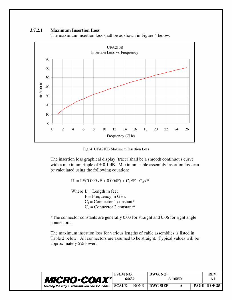
3.7.2.1 Maximum Insertion Loss
The maximum insertion loss shall be as shown in Figure 4 below:
Fig. 4 UFA210B Maximum Insertion Loss
The insertion loss graphical display (trace) shall be a smooth continuous curve with a maximum ripple of ± 0.1 dB. Maximum cable assembly insertion loss can be calculated using the following equation:
IL = L*(0.099√F + 0.004F) + C1√F+ C2√F
Where L = Length in feet F = Frequency in GHz C1 = Connector 1 constant* C2 = Connector 2 constant*
*The connector constants are generally 0.03 for straight and 0.06 for right angle connectors.
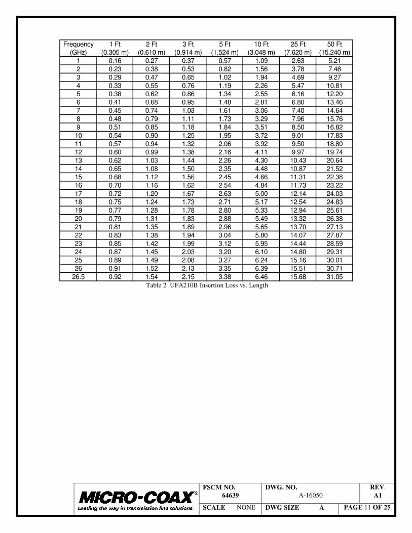
The maximum insertion loss for various lengths of cable assemblies is listed in Table 2 below. All connectors are assumed to be straight. Typical values will be approximately 5% lower.
UFA210BInsertion Loss vs Frequency
0
10
20
30
40
50
60
70
0 2 4 6 8 10 12 14 16 18 20 22 24 26
Frequency (GHz)
dB/1
00 ft
FSCM NO. DWG. NO. REV. 64639 A-16050 A1
SCALE NONE DWG SIZE A PAGE 11 OF 25
Frequency 1 Ft 2 Ft 3 Ft 5 Ft 10 Ft 25 Ft 50 Ft(GHz) (0.305 m) (0.610 m) (0.914 m) (1.524 m) (3.048 m) (7.620 m) (15.240 m)
1 0.16 0.27 0.37 0.57 1.09 2.63 5.212 0.23 0.38 0.53 0.82 1.56 3.78 7.483 0.29 0.47 0.65 1.02 1.94 4.69 9.274 0.33 0.55 0.76 1.19 2.26 5.47 10.815 0.38 0.62 0.86 1.34 2.55 6.16 12.206 0.41 0.68 0.95 1.48 2.81 6.80 13.467 0.45 0.74 1.03 1.61 3.06 7.40 14.648 0.48 0.79 1.11 1.73 3.29 7.96 15.769 0.51 0.85 1.18 1.84 3.51 8.50 16.8210 0.54 0.90 1.25 1.95 3.72 9.01 17.8311 0.57 0.94 1.32 2.06 3.92 9.50 18.8012 0.60 0.99 1.38 2.16 4.11 9.97 19.7413 0.62 1.03 1.44 2.26 4.30 10.43 20.6414 0.65 1.08 1.50 2.35 4.48 10.87 21.5215 0.68 1.12 1.56 2.45 4.66 11.31 22.3816 0.70 1.16 1.62 2.54 4.84 11.73 23.2217 0.72 1.20 1.67 2.63 5.00 12.14 24.0318 0.75 1.24 1.73 2.71 5.17 12.54 24.8319 0.77 1.28 1.78 2.80 5.33 12.94 25.6120 0.79 1.31 1.83 2.88 5.49 13.32 26.3821 0.81 1.35 1.89 2.96 5.65 13.70 27.1322 0.83 1.38 1.94 3.04 5.80 14.07 27.8723 0.85 1.42 1.99 3.12 5.95 14.44 28.5924 0.87 1.45 2.03 3.20 6.10 14.80 29.3125 0.89 1.49 2.08 3.27 6.24 15.16 30.0126 0.91 1.52 2.13 3.35 6.39 15.51 30.71
26.5 0.92 1.54 2.15 3.38 6.46 15.68 31.05 Table 2 UFA210B Insertion Loss vs. Length
FSCM NO. DWG. NO. REV. 64639 A-16050 A1
SCALE NONE DWG SIZE A PAGE 12 OF 25
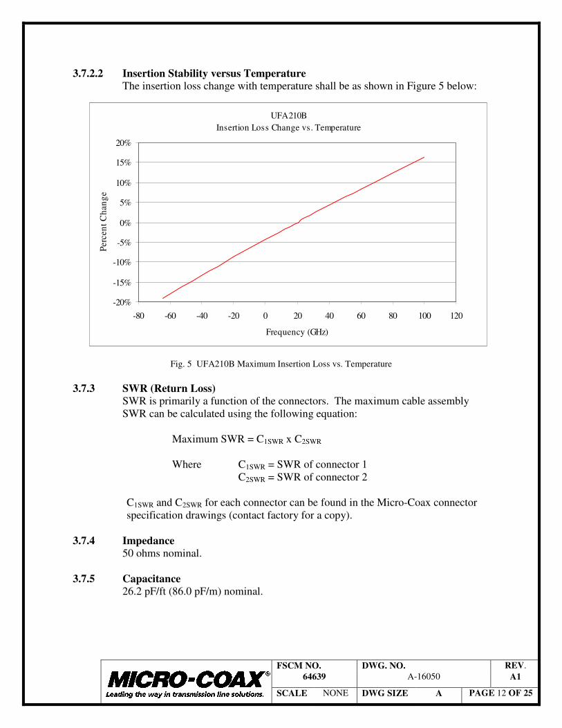
3.7.2.2 Insertion Stability versus Temperature
The insertion loss change with temperature shall be as shown in Figure 5 below:
Fig. 5 UFA210B Maximum Insertion Loss vs. Temperature
3.7.3 SWR (Return Loss) SWR is primarily a function of the connectors. The maximum cable assembly SWR can be calculated using the following equation:
Maximum SWR = C1SWR x C2SWR
Where C1SWR = SWR of connector 1 C2SWR = SWR of connector 2
C1SWR and C2SWR for each connector can be found in the Micro-Coax connector specification drawings (contact factory for a copy).
3.7.4 Impedance
50 ohms nominal. 3.7.5 Capacitance
26.2 pF/ft (86.0 pF/m) nominal.
UFA210BInsertion Loss Change vs. Temperature
-20%
-15%
-10%
-5%
0%
5%
10%
15%
20%
-80 -60 -40 -20 0 20 40 60 80 100 120
Frequency (GHz)
Perc
ent C
hang
e

FSCM NO. DWG. NO. REV. 64639 A-16050 A1
SCALE NONE DWG SIZE A PAGE 13 OF 25
3.7.6 Velocity of Propagation (Time Delay) 77% of the speed light, which equates to a time delay of 1.25 ns/ft (4.10 ns/m).
3.7.7 Electrical Phase 3.7.7.1 Phase Matching
Unless specified on the order, cable assemblies will not be phase matched. If phase matching is required, one of the following options must be detailed on the order.
3.7.7.1.1 Absolute Phase Matching
Consists of matching two or more assemblies to an absolute electrical length plus a tolerance. Generally, the absolute length is specified as an equivalent air-line length in inches or centimeters derived from actual measurements. Specifying the absolute length in this manner simplifies the measurement on modern vector network analyzers. In addition, it is often easier to specify the equivalent airline length after the first lot of cable assemblies have been manufactured, resulting in tighter mechanical length tolerances. Although tighter tolerances can be achieved, the default phase matching tolerance shall be 0.5°/GHz.
3.7.7.1.2 Relative Phase Matching
Consists of matching two or more assemblies relative to each other, not to an absolute length. Each assembly in a particular set will meet the matching criteria, however, it is unlikely that succeeding sets will match each other. As a result, assemblies that are ordered with relative phase matching should be ordered as sets. If one assembly within a set needs to be replaced, an entire new set must be ordered. Although tighter tolerances can be achieved, the default phase matching tolerance shall be 0.5°/GHz.
FSCM NO. DWG. NO. REV. 64639 A-16050 A1
SCALE NONE DWG SIZE A PAGE 14 OF 25
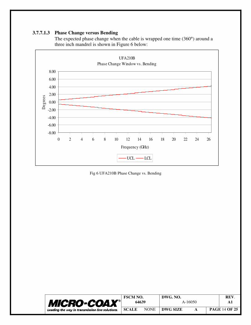
3.7.7.1.3 Phase Change versus Bending
The expected phase change when the cable is wrapped one time (360°) around a three inch mandrel is shown in Figure 6 below:
Fig 6 UFA210B Phase Change vs. Bending
UFA210BPhase Change Window vs. Bending
-8.00
-6.00
-4.00
-2.00
0.00
2.00
4.00
6.00
8.00
0 2 4 6 8 10 12 14 16 18 20 22 24 26
Frequency (GHz)
Deg
rees
UCL LCL

FSCM NO. DWG. NO. REV. 64639 A-16050 A1
SCALE NONE DWG SIZE A PAGE 15 OF 25
3.7.7.2 Phase Stability versus Temperature
Shall be as shown in Figure 7 below. The phase stability versus temperature may differ from the figure depending on the length of the cable assembly and the type of connectors.
Fig. 7 UFA210B Phase Change vs. Temperature
3.7.7.3 Phase Tracking
Phase tracking defines the difference in phase change between like cable assemblies with changing temperature. Cable assemblies of equal length and connectors made from the same cable manufacturing lot shall phase track within 200 PPM of each other.
3.7.8 RF Shielding
Shall be –90 dB minimum from 1 to 26.5 GHz. However, cable assembly shielding effectiveness can be limited by the connector design.
3.7.9 Passive Intermodulation (PIM)
PIM requirements must be specified. Standard cable assemblies are not rated for PIM. For low PIM requirements, Micro-Coax employs special connectors and assembly processes.
UFA210BPhase Stability vs. Temperature
-1000
-500
0
500
1000
1500
2000
2500
3000
-80 -60 -40 -20 0 20 40 60 80 100 120
Temp (degrees C)
PPM
UCL Nominal LCL

FSCM NO. DWG. NO. REV. 64639 A-16050 A1
SCALE NONE DWG SIZE A PAGE 16 OF 25
3.7.10 Corona Extinction (cable only) 2000 VRMS minimum at 60 Hz. Maximum operating voltage may be limited by the connector type, as detailed in the Micro-Coax connector specification drawings (contact factory for a copy).
3.7.11 Dielectric Withstanding Voltage (cable only)
5000 VRMS minimum at 60 Hz.
3.7.12 Power The average continuous wave (CW) power handling capability for the cable shall be as shown in Figure 8 below. Cable assembly power ratings may be limited by the connector type.
Fig. 8 UFA210B Power
3.7.13 Jacket Spark Test Cable jacket shall withstand 3000 VRMS without breakdown, flashover, or spark over.
UFA210BAverage Continuous Wave Power Handling
1
10
100
1000
10000
0 2 4 6 8 10 12 14 16 18 20 22 24 26
Frequency (GHz)
Pow
er (C
W)

FSCM NO. DWG. NO. REV. 64639 A-16050 A1
SCALE NONE DWG SIZE A PAGE 17 OF 25
3.8 ENVIRONMENTAL CHARACTERISITCS 3.8.1 Thermal Shock
Cable shall be capable of withstanding 40 thermal shocks from -65° to +125° C with minimal degradation to the cable performance.
3.8.2 Cold Bend
Cable, when wrapped 10 times around a 0.6 inch (15.2 mm) mandrel and conditioned at -40° C for 20 hours minimum, shall show no evidence of cracks, flaws, or other damage in the jacket material.
3.8.3 Stress Crack Resistance
Cable, when wrapped 10 times around a 0.6 inch (15.2 mm) mandrel and conditioned at 230° C for 96 hours minimum, shall show no evidence of cracks, flaws, or other damage in the jacket material.
3.8.4 Vibration Stability (Shake Test)
The cable phase and insertion loss change, while being vibrated at a frequency of 6 Hz and an amplitude of 1 inch (25.4 mm), shall not exceed 25 PPM and 5% respectively.
3.8.5 Humidity
The cable assembly shall be capable of withstanding the humidity requirements of MIL-STD-810, Method 507, Procedure III.
3.9 WORKMANSHIP
The cable assembly shall be manufactured and processed in such a manner as to be uniform in quality and shall be free from cracked or displaced parts, sharp edges, burrs, and other defects that will effect life and reliability.
4. QUALITY ASSURANCE PROVISIONS 4.1 GENERAL
The quality assurance provisions of MIL-C-17 shall apply with the exceptions and additions specified herein.
4.2 RESPONSIBILITY FOR INSPECTION
Micro-Coax, Inc. is responsible for the performance of all inspection and test specified herein. Micro-Coax, Inc. may use their own facilities or other suitable inspection services.
4.3 SOURCE INSPECTION
If source inspection is required, it must be specified

FSCM NO. DWG. NO. REV. 64639 A-16050 A1
SCALE NONE DWG SIZE A PAGE 18 OF 25
4.4 INSPECTION LOT
An inspection lot shall be defined as a production group which is manufactured in accordance with the same design and in an essentially continuous production run using the same materials and processes.
4.5 QUALIFICATION TEST
Cable assemblies supplied under this specification shall be capable of being tested and passing the qualification tests according to Table 5. Qualification shall consist of tests for both cable and assemblies. Qualification testing shall occur whenever a design change is made or a minimum of every 5 years.
4.5.1 Test Samples
No. Cable Type Connector Type (Both Ends) Length (in) Quantity 1 UFA210B 3.5 mm Plug 120 (3.05 m) 3 2 UFA210B 3.5 mm Plug 60 (1.52 m) 3 3 UFA210B 3.5 mm Plug 36 (0.91 m) 3 4 UFA210B 3.5 mm Plug 12 (0.30 m) 3 5 UFA210B None 120 (3.05 m) 3 6 UFA210B None 24 (0.61 m) 3 7 UFA210B None 12 (0.30 m) 3
Table 4 UFA210B Test Samples
4.6 ACCEPTANCE TESTING Acceptance testing shall consist of Group A, B, and C inspection.
4.6.1 Group A Inspection
Group A Inspection per Table 6 shall be performed on all cable assemblies supplied under this specification.
4.6.2 Group B Inspection
Group B Inspection shall be performed on a sampling of cable assemblies supplied under this specification as detailed in Table 6.
4.6.3 Group C Inspection
Group C Inspection as detailed in Table 6 shall be performed on each raw cable lot used in the cable assemblies supplied under this specification.
4.7 TEST METHODS
All measurements shall be made at room temperature and prevailing barometric pressure.

FSCM NO. DWG. NO. REV. 64639 A-16050 A1
SCALE NONE DWG SIZE A PAGE 19 OF 25
4.7.1 Insertion Loss
Insertion loss shall be measured on an automatic network analyzer in accordance with the applicable paragraph of MIL-C-17. The frequency range shall be from 0.05 to 26.5 GHz or as limited by the connectors. Markers shall be placed at 1, 10, 18, and 26.5 GHz. The marker frequencies shall be used for pass/fail criteria. A scale shall be chosen so that the vertical displacement of the graphical display (trace) will cover at least 50% of the screen.
4.7.2 SWR
SWR shall be measured on an automatic network analyzer in accordance with the applicable paragraph of MIL-C-17. The frequency range shall be from 0.05 to 26.5 GHz. Limit lines shall be set as required. The limit lines shall be used for pass/fail criteria.
4.7.3 Cable Dimensions
Finished cable shall be dismantled layer by layer and diameters measured using a micrometer with an accuracy of 0.0001 inch (0.0025 mm) minimum.
4.7.4 Minimum Static Bend Radius
Connect one end of cable to a Time Domain Reflectometer (TDR) with a rise time not greater than 150 picoseconds and observe the impedance profile. Then wrap cable around specified mandrel. The impedance profile shall not change more than the specified limit.
4.7.5 Minimum Dynamic Bend Radius
Install specified mandrels and connect one end of cable to flex (tic-toc) machine arm and hang a 5 pound (2.27 kg) weight on other end. Flex machine shall be capable of ± 90 degrees of movement with an accuracy of ± 5 degrees. Flex cable for specified number of cycles and then re-measure insertion loss and SWR per 4.7.1 and 4.7.2 respectively. Confirm that insertion loss and SWR are still within the specified limits.
4.7.6 Flex Life
Connect both ends of cable to flex (snake) machine. Flex machine shall be capable of 18 inches (457.2 mm) of movement with an accuracy of ± 1 inch (25.4 mm). Flex cable for specified number of cycles and then re-measure insertion loss and SWR per 4.7.1 and 4.7.2 respectively. Confirm that insertion loss and SWR are still within the specified limits.
4.7.7 Cable Weight
Measure cable length to an accuracy of ± 0.05 inch (12.7 mm). Then measure weight in grams using a scale with an accuracy of 0.01 grams minimum. Confirm that the measured weight is below the specified limit.

FSCM NO. DWG. NO. REV. 64639 A-16050 A1
SCALE NONE DWG SIZE A PAGE 20 OF 25
4.7.8 Cable Dimensional Stability
Flush cut cable ends and verify that all cable layers are within 0.01 inch to the end of the center conductor. Thermal shock cable for 40 cycles at –65 degrees C to +125 degrees C in accordance with MIL-STD-202, Method 107. Then measure the recession of any of the cable layers to confirm that they are within the specified limits.
4.7.9 Cable Compression Resistance
Lay cable between 3 ± 0.1 inch (76.2 ± 2.54 mm) parallel plates and apply the specified compressive force. The device applying the compressive force shall have an accuracy of 0.5 pounds (0.227 kg) minimum. Visually examine cable for damage and re-measure insertion loss and SWR per 4.7.1 and 4.7.2 respectively. Confirm that insertion loss and SWR are still within the specified limits.
4.7.10 Connector Retention
Connect one end of cable to a fixed point and hang the specified weight on the other end for 1 minute minimum. Visually examine cable for damage and remeasure insertion loss and SWR per 4.7.1 and 4.7.2 respectively. Confirm that insertion loss and SWR are still within the specified limits.
4.7.11 Coupling Mechanism Proof Torque
Using a torque wrench with a minimum accuracy of ± 0.5 pounds (0.227 kg), tighten connector coupling mechanism to a mating connector with the specified force in accordance with MIL-PRF-39012. Examine coupling mechanism for damage, misalignment, or any signs of being dislodged from the connector body. Loosen coupling mechanism and inspect per the requirement specified.
4.7.12 Assembly Length
Cable assembly length shall be determined by measuring the distance from connector reference plane to connector reference plane using a measuring device with an accuracy of 0.05 inch minimum. For right angle connectors measure from the connector center line.
4.7.13 Assembly Marking
Visually examine assembly markers and compare to the requirement. 4.7.14 Insertion Loss Versus Temperature
Place cable assembly inside of a thermal chamber that has an accuracy of ± 5 degrees Celsius minimum., and connect to test leads from an automatic network analyzer. The entire assembly must be inside the thermal chamber. Use standard routines for removing any test lead contribution from the measurement. Measure insertion loss at room temperature per 4.7.1. Lower temperature to –65 degrees C and repeat measurement. Gradually increase temperature and measure insertion loss at –40, –20, 0, 20, 25, 40, 60,and 100 degrees C. Plot results and compare to requirement.

FSCM NO. DWG. NO. REV. 64639 A-16050 A1
SCALE NONE DWG SIZE A PAGE 21 OF 25
4.7.15 Phase Stability Versus Temperature Place cable assembly inside of a thermal chamber that has an accuracy of ± 5 degrees Celsius, and connect to test leads from an automatic network analyzer. The entire assembly must be inside the thermal chamber. Use standard routines for removing any test lead contribution from the measurement. Phase at room temperature. Lower temperature to –65 degrees C and repeat measurement. Gradually increase temperature and measure phase at –40, –20, 0, 20, 25, 40, 60,and 100 degrees C. Plot results and compare to requirement.
4.7.16 Impedance
Connect one end of cable to a Time Domain Reflectometer (TDR) and compare cable impedance to a 50 ohm air-line standard in accordance with the applicable paragraph of MIL-C-17.
4.7.17 Capacitance
Measure cable length to an accuracy of ± 0.05 inch. Then measure capacitance in picofarads in accordance with the applicable paragraph of MIL-C-17. Divide the measured capacitance by the length to determine the capacitance per foot and confirm that it is within the specified limit.
4.7.18 Velocity of Propagation
Measure cable length to an accuracy of ± 0.05 inch (1.27 mm). Then connect cable assembly to an automatic network analyzer and measure group delay. Calculate the velocity of propagation using the following equation:
V of P = 101.6 x Length (ft) / Group Delay (ns) 4.7.19 Phase Change Versus Bending
Using no test leads, connect both ends of the cable assembly to an automatic network analyzer. Normalize the phase using divide by memory function or equivalent. Disconnect one end of the cable assembly and wrap cable one time (360°) around the specified mandrel diameter. Reconnect loose end of the cable assembly to automatic network analyzer and observe the phase change to determine if it is within the specified limits.
4.7.20 Phase Tracking Versus Temperature
Place cable assembly inside of a thermal chamber that has an accuracy of ± 5 degrees Celsius, and connect to test leads from an automatic network analyzer. The entire assembly must be inside the thermal chamber. Use standard routines for removing any test lead contribution from the measurement. Test phase at room temperature. Lower temperature to –65 degrees C and repeat measurement. Gradually increase temperature and measure phase at –40, –20, 0, 20, 25, 40, 60,and 100 degrees C. Plot results and compare to requirement.

FSCM NO. DWG. NO. REV. 64639 A-16050 A1
SCALE NONE DWG SIZE A PAGE 22 OF 25
4.7.21 RF Shielding
The cable assembly shall be placed in reverberation chamber outfitted with a mode stirrer in accordance with MIL-STD-1344, Method 3008. A continuous wave signal shall be generated, amplified, and transmitted into the chamber via a double ridged horn antenna. A spectrum analyzer shall be used to measure power coupled out of the chamber via a second double ridged horn antenna. A separate analyzer shall be used to measure the power coupled out of the chamber by the assembly. To perform the measurement, a system calibration shall be obtained from .05 to 18 GHz to determine the cable/adapter losses and antenna gains for each path. Next, system dynamic range shall be obtained by measuring a well shielded load. Then, one end of the assembly shall be connected to a spectrum analyzer and the other end to a 50 ohm shielded load. Measurements shall be made at the specified frequency range with a 2 GHz step size. The RF shielding shall be calculated per the following:
RF Shielding = PCABLE - PREF - Cal Factor
Where PCABLE is the signal measured through the assembly, PREF is the incident signal in the chamber, and Cal Factor is the measured combination of test cable/adapter loses and antenna gains.
4.7.22 Corona Extinction
Strip one inch of the outer shield, exposing the dielectric, from both ends of the cable to be tested. Connect one end of cable to test leads of corona test set and measure in accordance with the applicable paragraph of MIL-C-17.
4.7.23 Dielectric Withstanding Voltage
Strip one inch of the outer shield, exposing the dielectric, from both ends of the cable to be tested. Connect one end of cable to test leads of dielectric withstanding voltage test set and measure in accordance with the applicable paragraph of MIL-C-17.
4.7.24 Thermal Shock
Thermal shock cable assembly for 40 cycles at –65 degrees C to +125 degrees C in accordance with MIL-STD-202, Method 107, and then remeasure insertion loss and SWR per 4.7.1 and 4.7.2 respectively. Confirm that insertion loss and SWR are still within the specified limits.
4.7.25 Cold Bend
Wrap cable around a 0.6 inch (15.2 mm) mandrel 10 times and secure the ends. Place cable inside of thermal chamber and condition at –40 degrees C for 20 hours minimum. Remove cable from chamber and visually examine jacket per the specified criteria.

FSCM NO. DWG. NO. REV. 64639 A-16050 A1
SCALE NONE DWG SIZE A PAGE 23 OF 25
4.7.26 Stress Crack Resistance Wrap cable around a 0.6 inch (15.2 mm) mandrel 10 times and secure the ends. Place cable inside of thermal chamber and condition at 230 degrees C for 96 hours minimum. Remove cable from chamber and visually examine jacket per the specified criteria.
4.7.27 Vibration Stability (Shake Test)
Place coiled cable assembly on vibration table. Coil shall be loose with no tie wraps or tie downs. Connect cable assembly to an automatic network analyzer. Vibrate cable assembly at the specified frequency and amplitude. Monitor insertion loss and phase change and compare to specified limits.
4.7.28 Humidity
Install sealed caps or equivalent to both connectors on the cable assembly and torque to the recommended value. Place cable assembly in thermal/humidity chamber and cycle per MIL-STD-810, Method 108, Procedure III. Then re-measure insertion loss and SWR per 4.7.1 and 4.7.2 respectively. Confirm that insertion loss and SWR are still within the specified limits.
4.7.29 Jacket Spark Test
The specified voltage shall be continuously applied to the jacket in accordance with the applicable paragraph of MIL-C-17.
4.7.30 Connector Interface Dimensions
Shall be measured in accordance with the applicable paragraph of MIL-PRF-39012.
4.7.31 Workmanship
Visually examine cable assembly per the specified requirements. 5. PREPARATION FOR DELIVERY 5.1 PACKAGING
Cable assemblies shall be packaged in shock absorbent material and placed in cardboard boxes for shipment. The cable assemblies will be loosely coiled in a diameter of approximately 16 inches (406 mm).
5.2 LABELING
Any special labeling requirements must be specified. 6. ORDERING INFORMATION
When ordering cable assemblies to this specification, the order must specify the assembly length, connector types, and quantity as a minimum. If additional options are required, like armoring, phase matching, or special marking, they must be clearly detailed on the order.

FSCM NO. DWG. NO. REV. 64639 A-16050 A1
SCALE NONE DWG SIZE A PAGE 24 OF 25
Sample No. Test Requirement Method
1, 2, 3 Insertion Loss 3.7.2 4.7.1 1, 2, 3 SWR 3.7.3 4.7.2
6 Cable Dimensions 3.6.1 4.7.3 3 Minimum Static Bend Radius 3.6.5 4.7.4
2 Minimum Dynamic Bend Radius 3.6.6 4.7.5
3 Flex Life 3.6.7 4.7.6 5 Cable Weight 3.6.8 4.7.7 5 Cable Dimensional Stability 3.6.9 4.7.8 2 Cable Compression Resistance 3.6.10 4.7.9 4 Connector Retention 3.6.11 4.7.10
3 Coupling Mechanism Proof Torque 3.6.13 4.7.11
1, 2, 3 Assembly Length 3.6.14 4.7.12 1, 2, 3 Assembly Marking 3.6.15 4.7.13
1 Insertion Loss vs. Temperature 3.7.2.2 4.7.14 5 Impedance 3.7.4 4.7.16 5 Capacitance 3.7.5 4.7.17 1 Velocity of Propagation 3.7.6 4.7.18 3 Phase Change vs. Bending 3.7.7.1.3 4.7.19
1 Phase Stability vs. Temperature 3.7.7.2 4.7.15
1 Phase Tracking 3.7.7.3 4.7.20 1 RF Shielding 3.7.8 4.7.21 5 Corona Extinction 3.7.10 4.7.22
5 Dielectric Withstanding Voltage 3.7.11 4.7.23
6 Thermal Shock 3.8.1 4.7.24 6 Cold Bend 3.8.2 4.7.25 6 Stress Crack Resistance 3.8.3 4.7.26 1 Vibration (Shake Test) 3.8.4 4.7.27 2 Humidity 3.8.5 4.7.28
Table 5 Qualification Testing

FSCM NO. DWG. NO. REV. 64639 A-16050 A1
SCALE NONE DWG SIZE A PAGE 25 OF 25
Group Test Requirement Method Sampling
A Insertion Loss 3.7.2 4.7.1 100% A SWR 3.7.3 4.7.2 100% A Connector Interface 3.6.2 4.7.30 100% A Assembly Marking 3.6.15 4.7.13 100% A Workmanship 3.9 4.7.31 100% B Assembly Length 3.6.14 4.7.12 2.5 AQL C Jacket Spark Test 3.7.13 4.7.29 100% C Impedance 3.7.4 4.7.16 100% C Cable Diameter 3.6.1 4.7.3 100% C Velocity of Propagation 3.7.6 4.7.18 2 pcs./lot C Vibration Stability (Shake
Test) 3.8.4 4.7.27 2 pcs./lot
C Jacket Wall Thickness 3.6.1 4.7.3 2 pcs./lot C Braid Diameter 3.6.1 4.7.3 2 pcs./lot C Inner Shield Diameter 3.6.1 4.7.3 2 pcs./lot C Dielectric Diameter 3.6.1 4.7.3 2 pcs./lot C Center Conductor
Diameter 3.6.1 4.7.3 2 pcs./lot
C Cable Weight 3.6.8 4.7.7 2 pcs./lot C Dimensional Stability 3.6.9 4.7.8 2 pcs./lot
Table 6 Acceptance Testing