MICOM-Z HF-SSB TRANSCEIVERS - DX Engineering · om-e 2072-09584-00 operator manual for micom-z...
139
OM-E 2072-09584-00 OPERATOR MANUAL FOR MICOM-Z HF-SSB TRANSCEIVERS Revision A March 2014
Transcript of MICOM-Z HF-SSB TRANSCEIVERS - DX Engineering · om-e 2072-09584-00 operator manual for micom-z...
OM-E 2072-09584-00
OPERATOR MANUAL
FOR
MICOM-Z
HF-SSB TRANSCEIVERS
Revision A
March 2014


OM-E 2072-09584-00
i
WARNINGS, CAUTIONS AND NOTESThe following notations are used to place special emphasis on procedures, or to call attention toprecautionary measures.
WARNINGAn operating procedure, practice and so forth, which if not followedcorrectly, could result in personal injury, or loss of life.
CAUTIONAn operating procedure, practice and so forth, which if not followedcorrectly, could result in damage to, or destruction of equipment.
NOTEAn operating procedure, condition and so forth, to which specialattention should be paid.
GENERAL SAFETY PRECAUTIONS
During transmission, high RF voltages may appear at the RFconnectors of the transceiver, antenna tuner (ATU), the antenna cable,and on the antenna itself.Avoid touching the antenna and the RF connectors of a radio set whileit operates.Make sure the antenna is not located near high-voltage lines.Operating and maintenance personnel must be familiar with theapplicable safety requirements and regulations before attempting toinstall or operate the radio set.

OM-E 2072-09584-00
ii
SAFETY SUMMARY
The following are general safety precautions that are not related to any specific procedures andtherefore do not appear elsewhere in this publication. These are recommended precautions thatpersonnel must understand and apply during various phases of operation and maintenance.
KEEP AWAY FROM LIVE CIRCUITS. Operating personnel must at all times observe all safetyregulations. Do not replace components or make adjustments inside the equipment with the highvoltage supply turned on. Under certain conditions, dangerous potentials may exist even when thepower control is in the OFF position, due to charges retained by capacitors. To avoid casualties,always remove power and discharge and ground a circuit before touching it.
DO NOT SERVICE OR ADJUST ALONE. Under no circumstances should any person reach into theequipment enclosure for the purpose of servicing or adjusting the equipment except in the presence ofsomeone who is capable of rendering aid.
RESUSCITATION. Personnel working with or near high voltages should be familiar with modernmethods of resuscitation.
USE SAFETY APPROVED EQUIPMENT. When cleaners and primers are being applied, approvedexplosion-proof lights, blowers, and other equipment shall be used. Insure that firefighting equipment isreadily available and in working order.
GIVE CLEANERS SPECIAL CARE. Keep cleaners in special polyethylene bottles or in safety cansand in minimum quantities. Discard soiled cleaning cloths into safety cans.
BURN INJURY. When touching transceiver body while operating the radio in ambient temperatureabove 55 degrees Celsius, heat preventive gloves shall be used.
FIRE HAZARD for Finland, Norway, Sweden:
In Finland, Norway and Sweden unit shall be installed in restricted access location only.
Equipment connected to the protective earthing of the building installation through the mainsconnection or through other equipment with a connection to protective earthing – and to a cabledistribution system using coaxial cable, may in some circumstances create a fire hazard. Connection toa cable distribution system has therefore to be provided through a device providing electrical isolationbelow a certain frequency range (galvanic isolator, see EN 60728-11).
Norwegian:
Utstyr som er koplet til beskyttelsesjord via nettplugg og/eller via annet jordtilkoplet
utstyr – og er tilkoplet et kabel-TV nett, kan forårsake brannfare. For å unngå dette skal det vedtilkopling av utstyret til kabel-TV nettet installeres en galvanisk isolator mellom utstyret og kabel- TVnettet.
Swedish:
Utrustning som är kopplad till skyddsjord via jordat vägguttag och/eller via annan
utrustning och samtidigt är kopplad till kabel-TV nät kan i vissa fall medfőra risk főr
brand. Főr att undvika detta skall vid anslutning av utrustningen till kabel-TV nät
galvanisk isolator finnas mellan utrustningen och kabel-TV nätet.

OM-E 2072-09584-00
iii
TABLE OF CONTENTSPage
CHAPTER 1 GENERAL DESCRIPTION1-1. SCOPE .......................................................................................................................... 1-11-2. OVERVIEW OF MICOM-Z CAPABILITIES................................................................... 1-11-3. EQUIPMENT DESCRIPTION........................................................................................ 1-3
1-3.1 Options and Accessories............................................................................... 1-31-3.2 Micom-Z Transceiver..................................................................................... 1-41-3.3 Installation Accessories ................................................................................. 1-5
1-4. TYPICAL SYSTEM CONFIGURATIONS ...................................................................... 1-61-5. TECHNICAL CHARACTERISTICS ............................................................................... 1-9
CHAPTER 2 OPERATING PROCEDURES2-1. SCOPE .......................................................................................................................... 2-12-2. FAMILIARIZATION WITH EQUIPMENT PANELS........................................................ 2-1
2-2.1 Dash-Mount Model, Front Panel.................................................................... 2-12-2.2 Trunk-Mount Model ....................................................................................... 2-22-2.3 Rear Panel (All Models)................................................................................. 2-3
2-3. FAMILIARIZATION WITH MICOM-Z OPERATING PROCEDURES............................ 2-42-3.1 Display Functions .......................................................................................... 2-42-3.2 Using the Keypad .......................................................................................... 2-52-3.3 Function Keys ................................................................................................ 2-62-3.4 Options Scroll Key ......................................................................................... 2-62-3.5 Up/Down Scroll Keys ..................................................................................... 2-62-3.6 Selection from List of Predetermined Values ................................................ 2-72-3.7 Toggle Mode.................................................................................................. 2-72-3.8 Alphanumeric Edit Mode................................................................................ 2-72-3.9 Numeric Edit Mode ........................................................................................ 2-72-3.10 Audible Indications......................................................................................... 2-8
2-4. MENU STRUCTURE..................................................................................................... 2-92-4.1 Displaying the Main Menu.............................................................................. 2-92-4.2 What you can Select on the Main Menu........................................................ 2-92-4.3 Notational Convention ................................................................................. 2-10
2-5. GETTING STARTED................................................................................................... 2-112-5.1 Turning the Radio On and Off ..................................................................... 2-112-5.2 Transmitting and Receiving ......................................................................... 2-122-5.3 Radio Filter Bandwidth and Service Type.................................................... 2-12
2-6. USING THE CHANNEL MODE................................................................................... 2-132-6.1 Selecting the Channel Mode........................................................................ 2-132-6.2 Channel Mode Options ................................................................................ 2-142-6.3 Choosing a Different Channel ..................................................................... 2-16
2-7. USING THE FREQUENCY MODE.............................................................................. 2-172-7.1 Frequency Mode Options ............................................................................ 2-172-7.2 Selecting Operating Frequency in the FREQ Mode .................................... 2-182-7.3 VFO Operation............................................................................................. 2-202-7.4 Storing Frequencies..................................................................................... 2-20
2-8. USING THE SCAN MODE .......................................................................................... 2-212-9. USING THE GPS RECEIVER (OPTIONAL) ............................................................... 2-23
2-9.1 Overview of GPS Receiver Functions ......................................................... 2-232-9.2 How to Get the Best Results from your Micom-Z GPS Receiver ................ 2-232-9.3 Operating the GPS Receiver ....................................................................... 2-23
2-10. LOCKING/UNLOCKING THE RADIO ......................................................................... 2-262-11. CHANGING THE PASSWORD................................................................................... 2-272-12. USING AUTOMATIC LINK ESTABLISHMENT (ALE)................................................. 2-28
2-12.1 Enabling the ALE Mode ............................................................................... 2-282-12.2 ALE Mode Options....................................................................................... 2-292-12.3 Receiving and Transmitting Calls in ALE Mode .......................................... 2-302-12.4 Using ALE Mode to Send and Request GPS Position Data........................ 2-49
OM-E 2072-09584-00
iv
TABLE OF CONTENTS (Cont'd)Page
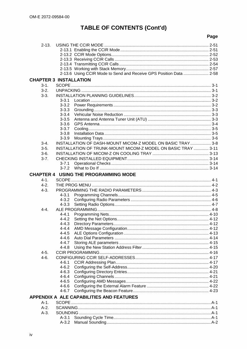
2-13. USING THE CCIR MODE ........................................................................................... 2-512-13.1 Enabling the CCIR Mode............................................................................. 2-512-13.2 CCIR Mode Options..................................................................................... 2-522-13.3 Receiving CCIR Calls .................................................................................. 2-532-13.4 Transmitting CCIR Calls .............................................................................. 2-542-13.5 Working with Stack Memory........................................................................ 2-572-13.6 Using CCIR Mode to Send and Receive GPS Position Data ...................... 2-58
CHAPTER 3 INSTALLATION3-1. SCOPE .......................................................................................................................... 3-13-2. UNPACKING ................................................................................................................. 3-13-3. INSTALLATION PLANNING GUIDELINES................................................................... 3-2
3-3.1 Location ......................................................................................................... 3-23-3.2 Power Requirements ..................................................................................... 3-23-3.3 Grounding...................................................................................................... 3-33-3.4 Vehicular Noise Reduction ............................................................................ 3-33-3.5 Antenna and Antenna Tuner Unit (ATU) ....................................................... 3-33-3.6 GPS Antenna................................................................................................. 3-43-3.7 Cooling........................................................................................................... 3-53-3.8 Installation Data ............................................................................................. 3-53-3.9 Mounting Trays .............................................................................................. 3-6
3-4. INSTALLATION OF DASH-MOUNT MICOM-Z MODEL ON BASIC TRAY.................. 3-83-5. INSTALLATION OF TRUNK-MOUNT MICOM-Z MODEL ON BASIC TRAY ............. 3-113-6. INSTALLATION OF MICOM-Z ON COOLING TRAY ................................................. 3-133-7. CHECKING INSTALLED EQUIPMENT....................................................................... 3-14
3-7.1 Operational Checks ..................................................................................... 3-143-7.2 What to Do If ............................................................................................... 3-14
CHAPTER 4 USING THE PROGRAMMING MODE4-1. SCOPE .......................................................................................................................... 4-14-2. THE PROG MENU ........................................................................................................ 4-24-3. PROGRAMMING THE RADIO PARAMETERS ............................................................ 4-3
4-3.1 Programming Channels................................................................................. 4-54-3.2 Configuring Radio Parameters ...................................................................... 4-64-3.3 Setting Radio Options.................................................................................... 4-7
4-4. ALE PROGRAMMING................................................................................................... 4-84-4.1 Programming Nets....................................................................................... 4-104-4.2 Setting the Net Options................................................................................ 4-124-4.3 Directory Parameters................................................................................... 4-124-4.4 AMD Message Configuration....................................................................... 4-124-4.5 ALE Options Configuration .......................................................................... 4-134-4.6 Auto Dial Parameters .................................................................................. 4-144-4.7 Storing ALE parameters .............................................................................. 4-154-4.8 Using the New Station Address Filter .......................................................... 4-15
4-5. CCIR PROGRAMMING............................................................................................... 4-164-6. CONFIGURING CCIR SELF-ADDRESSES................................................................ 4-17
4-6.1 CCIR Addressing Plan................................................................................. 4-174-6.2 Configuring the Self-Address....................................................................... 4-204-6.3 Configuring Directory Entries....................................................................... 4-214-6.4 Configuring Channels .................................................................................. 4-214-6.5 Configuring AMD Messages........................................................................ 4-224-6.6 Configuring the External Alarm Feature ...................................................... 4-224-6.7 Configuring the Beacon Feature.................................................................. 4-23
APPENDIX A ALE CAPABILITIES AND FEATURESA-1. SCOPE ..........................................................................................................................A-1A-2. SCANNING....................................................................................................................A-1A-3. SOUNDING ...................................................................................................................A-1
A-3.1 Sounding Cycle Time.....................................................................................A-1A-3.2 Manual Sounding...........................................................................................A-2

OM-E 2072-09584-00
v
TABLE OF CONTENTS (Cont'd)Page
A-4. LQA MEMORY ..............................................................................................................A-3A-5. BIDIRECTIONAL HANDSHAKE....................................................................................A-3A-6. SELECTIVE CALLING ..................................................................................................A-4
A-6.1 ALE Addressing Method................................................................................A-4A-6.2 Address and Call Types.................................................................................A-4
A-7. MESSAGES...................................................................................................................A-8A-8. USING THE CALLER STACK.......................................................................................A-8A-9. QUICK CALL .................................................................................................................A-8
APPENDIX B CONNECTOR DATAB-1. MICOM-Z TRANSCEIVER CONNECTORS .................................................................B-1
B-1.1 Microphone Connector ..................................................................................B-1B-1.2 Antenna Connector........................................................................................B-1B-1.3 ACCESSORY Connector...............................................................................B-1B-1.4 VDC IN Power Connector..............................................................................B-3
B-2. COOLING TRAY CONNECTORS.................................................................................B-3B-2.1 44-Pin/25-Pin Adapter Cable .........................................................................B-3B-2.2 ACCESSORY Connector...............................................................................B-4B-2.3 Headphone Jack............................................................................................B-4B-2.4 Telegraphy (Morse) Jack...............................................................................B-4
APPENDIX C OVER-THE-AIR REMOTE DISABLE FUNCTIONC-1. SCOPE ..........................................................................................................................C-1C-2. OVERVIEW ...................................................................................................................C-1C-3. OPERATING INSTRUCTIONS .....................................................................................C-1C-4. RESTORING THE RADIO TO NORMAL OPERATION................................................C-1

OM-E 2072-09584-00
vi
LIST OF ILLUSTRATIONS
Page
Figure 1-1. Typical Trunk-Mount Micom-Z Installation................................................................................ 1-6Figure 1-2. Typical Dash-Mount Micom-Z Installation................................................................................. 1-7Figure 1-3. Typical Dash-Mount Micom-Z Installation Using FAD1410 ..................................................... 1-8
Figure 2-1. Main Menu.................................................................................................................................. 2-9Figure 2-2. Channel (CHAN) Menu............................................................................................................ 2-14Figure 2-3. FREQ (Frequency) Menu ........................................................................................................ 2-17Figure 2-4. GPS Menu................................................................................................................................ 2-24Figure 2-5. ALE Operator Menu ................................................................................................................. 2-29Figure 2-6. CCIR Operator Menu............................................................................................................... 2-52
Figure 3-1. FPN5600 Power Supply Connections....................................................................................... 3-2Figure 3-2. Suggested Mobile Installations Using ATU............................................................................... 3-4Figure 3-3. Suggested Mobile Installations Using FAD1410 ...................................................................... 3-4Figure 3-4. Dash-Mount Micom-Z Dimensions ........................................................................................... 3-5Figure 3-5. Installation Data for Trunk-Mount Control Head....................................................................... 3-6Figure 3-6. Hole Pattern for Basic Mounting Tray ....................................................................................... 3-6Figure 3-7. Cooling Tray ............................................................................................................................... 3-7Figure 3-8. Cooling Tray Dimensions and Mounting Hole Pattern ............................................................. 3-7Figure 3-9. Typical Dash-Mount Micom-Z Installation Diagram (Basic Tray) ............................................ 3-8Figure 3-10. Typical Dash-Mount Micom-Z Installation within Vehicle ......................................................... 3-9Figure 3-11. Typical Trunk-Mount Micom-Z Installation Diagram............................................................... 3-11Figure 3-12. Typical Trunk-Mount Micom-Z Installation within Vehicle (Basic Tray) ................................. 3-12
Figure 4-1. PROG Menu – Radio Parameters Programming..................................................................... 4-3Figure 4-2. PROG Menu – ALE Parameters Programming ....................................................................... 4-8Figure 4-3. PROG Menu – CCIR Parameters Programming................................................................... 4-16Figure 4-4. Groups and Sub-Groups in Four-Digit CCIR Addressing Plan.............................................. 4-19Figure 4-5. Groups and Sub-Groups in Six-Digit CCIR Addressing Plan ................................................ 4-19
Figure A-1. Network Occupancy...................................................................................................................A-2
OM-E 2072-09584-00
vii
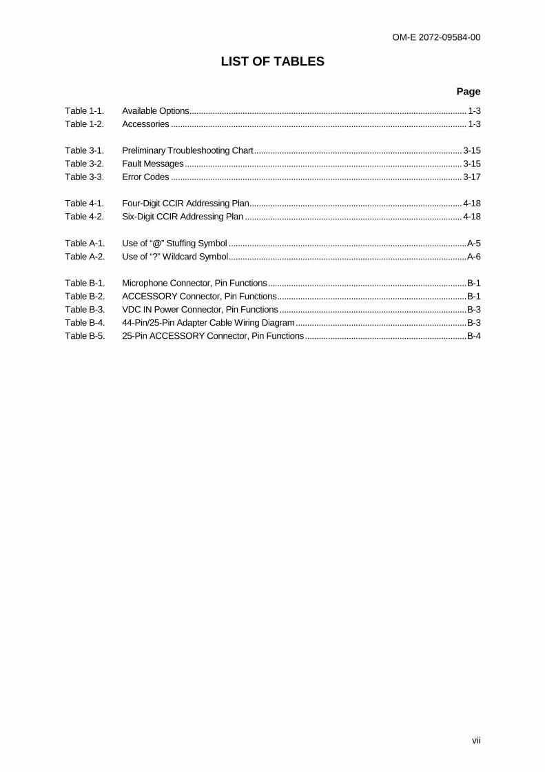
LIST OF TABLES
Page
Table 1-1. Available Options........................................................................................................................ 1-3Table 1-2. Accessories ................................................................................................................................ 1-3
Table 3-1. Preliminary Troubleshooting Chart.......................................................................................... 3-15Table 3-2. Fault Messages........................................................................................................................ 3-15Table 3-3. Error Codes .............................................................................................................................. 3-17
Table 4-1. Four-Digit CCIR Addressing Plan............................................................................................ 4-18Table 4-2. Six-Digit CCIR Addressing Plan .............................................................................................. 4-18
Table A-1. Use of “@” Stuffing Symbol .......................................................................................................A-5Table A-2. Use of “?” Wildcard Symbol.......................................................................................................A-6
Table B-1. Microphone Connector, Pin Functions......................................................................................B-1Table B-2. ACCESSORY Connector, Pin Functions..................................................................................B-1Table B-3. VDC IN Power Connector, Pin Functions .................................................................................B-3Table B-4. 44-Pin/25-Pin Adapter Cable Wiring Diagram..........................................................................B-3Table B-5. 25-Pin ACCESSORY Connector, Pin Functions......................................................................B-4

OM-E 2072-09584-00
viii
Intentionally Left Blank

OM-E 2072-09584-00
1-1
CHAPTER 1
GENERAL DESCRIPTION
1-1. SCOPEThis manual provides instructions regarding the installation and operator maintenance of the Micom-Zfamily of adaptive high-frequency (HF) single sideband (SSB) radio sets. The manual is organized asfollows:
Chapter 1 General Description: provides a general description of the Micom-Z and its maincomponents, and presents the main technical characteristics.
Chapter 2 Operating Procedures: provides the information needed to familiarize with theMicom-Z panels, general procedures for using the Micom-Z keypad and display toperform any desired task, and detailed operating procedures for each main radiooperating mode.
Chapter 3 Installation: provides installation instructions for Micom-Z in fixed and mobileapplications.
Chapter 4 Using the Programming Mode: provides detailed instructions for programming theMicom-Z parameters needed in the various operating modes.
Appendix A ALE Capabilities and Features: provides a concise description of the ALEcapabilities and features supported by Micom-Z.
Appendix B Connector Data: provides information on pin assignment and pin functions in theMicom-Z connectors, and its accessories.
Appendix C Over-the-Air Remote Disable Function: describes the over-the-air remote disablecapability of Micom-Z.
1-2. OVERVIEW OF MICOM-Z CAPABILITIESMicom-Z is a state-of-art family of adaptive HF/SSB radio sets designed to meet the demandingrequirements of the operational environment. Using advanced digital signal processing (DSP)techniques, Micom-Z offers reliable long-range communication for voice, data, and telegraphy (CW)using upper sideband (USB), lower sideband (LSB), amplitude modulation equivalent (AME), andpilot modes of operation.
Micom-Z radio sets provide a complete solution to traditional HF communication problems whileallowing user-friendly, easy operation even for unskilled users. Micom-Z radio sets have beenspecifically designed to satisfy all the needs of short, medium and long range communication in thecrowded HF band.
The main characteristics of the Micom-Z family are described below:
Micom-Z transceivers are offered in two flexible configurations: dash-mount and trunk-mount,designed to fit both fixed and mobile installations. To simplify installation, the transceivers canalso provide power through the RF cable to a compatible ATU.
User-Friendly Operation. Designed to render its cutting-edge features usable by unskilled users,the Micom-Z has an intelligent, state-of-the-art, menu-driven man-machine interface (MMI) thatis easy to master, and intuitive to use. The MMI is based on a large digital front-panel displaywith four soft keys, and a standard 16-key keypad; the only additional front-panel control is theradio ON/OFF switch.
OM-E 2072-09584-00
1-2
The MMI enables the operator to perform any desired action easily and efficiently, for example,select the desired operating mode, define or modify the parameters to be used on each presetchannel, etc. Many improvements based on user feedback have been incorporated in the MMI, asa part of an ongoing evaluation program.
In addition, Micom-Z radio sets enable PC control and programming, via an RS-232 interface.
Robust, Reliable Link Establishment. Micom-Z radio sets support Automatic Link Establishment(ALE) per MIL-STD-188-141B (the required software is supplied embedded as a standard), ALEoperation is very simple, and can be easily used even by unskilled operators.
In addition, Micom-Z also supports CCIR 493 SelCal (selective calling) with 4-digit and 6-digitaddressing per UN-WGET Interoperability Agreement, and beacon calls.
Both ALE and CCIR 493 SelCal are interoperable with all the major suppliers supporting thestandards. When operating in the ALE or CCIR modes, Micom-Z provide an over-the-air remotedisable function: an authorized radio set can transmit a command to a radio which has been lostor stolen to disable all the radio programmable parameters.
Internal GPS Receiver. The Micom-Z can be ordered with an optional integral Global PositioningSystem (GPS) receiver. In addition to presenting the GPS information on the display, the ALEAMD or the CCIR 493 Recall GPS call messaging platforms can be used to enable any station togenerate a request for GPS location from any other station in the network.
The GPS receiver uses a compact, light-weight patch antenna with magnetic mount.
High Reliability and Cost-Effective Logistics. The modular, 3-board design of the Micom-Zfamily, with its high MTBF and low MTTR, offers outstanding reliability in field conditions andcost-effective logistic support.
A comprehensive multilevel built-in test (BIT) subsystem helps the user to identify faultymodules in the field, and ensures complete functional testing after module replacement. The BITalso provides valuable information to higher echelon maintenance personnel, without requiringmodule-level test equipment.
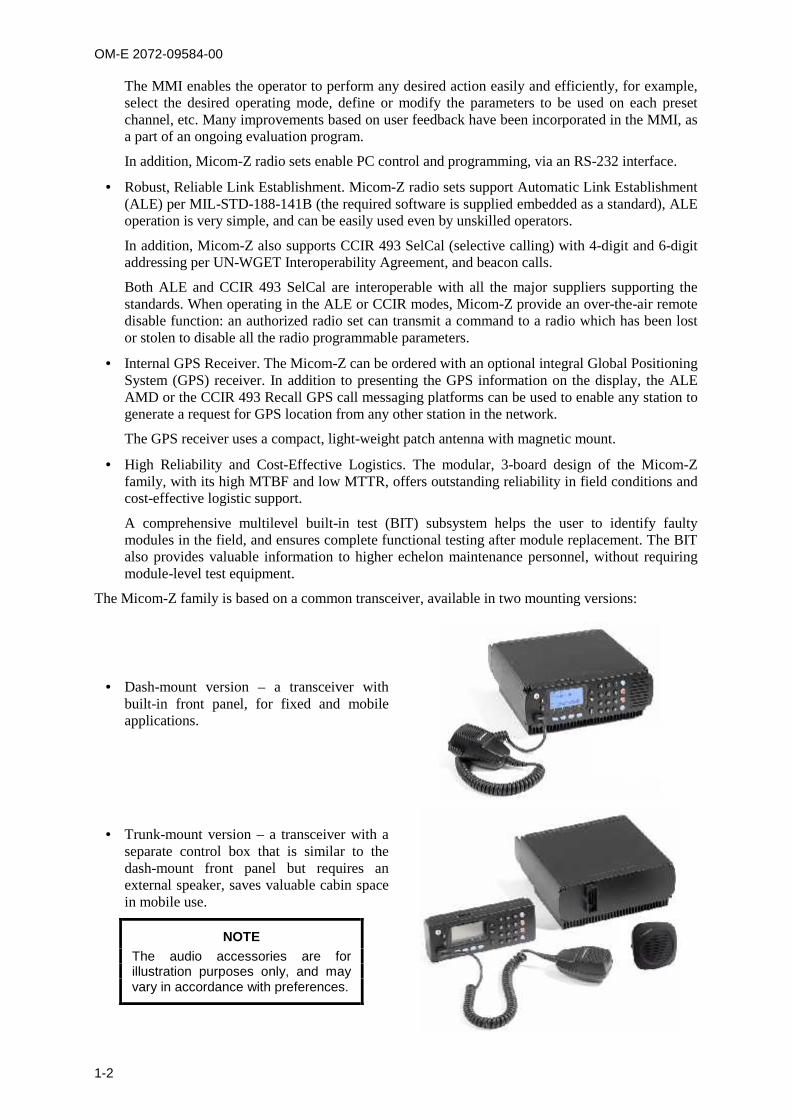
The Micom-Z family is based on a common transceiver, available in two mounting versions:
Dash-mount version – a transceiver withbuilt-in front panel, for fixed and mobileapplications.
Trunk-mount version – a transceiver with aseparate control box that is similar to thedash-mount front panel but requires anexternal speaker, saves valuable cabin spacein mobile use.
NOTEThe audio accessories are forillustration purposes only, and mayvary in accordance with preferences.
OM-E 2072-09584-00
1-3
1-3. EQUIPMENT DESCRIPTIONThis section describes the main equipment units of the Micom-Z radio set, and lists the options andaccessories available for ordering.
1-3.1 Options and Accessories
The following tables list the options and accessories that can be ordered for Micom-Z. Contact themanufacturer or your local representative if you need an option or accessory not listed below.
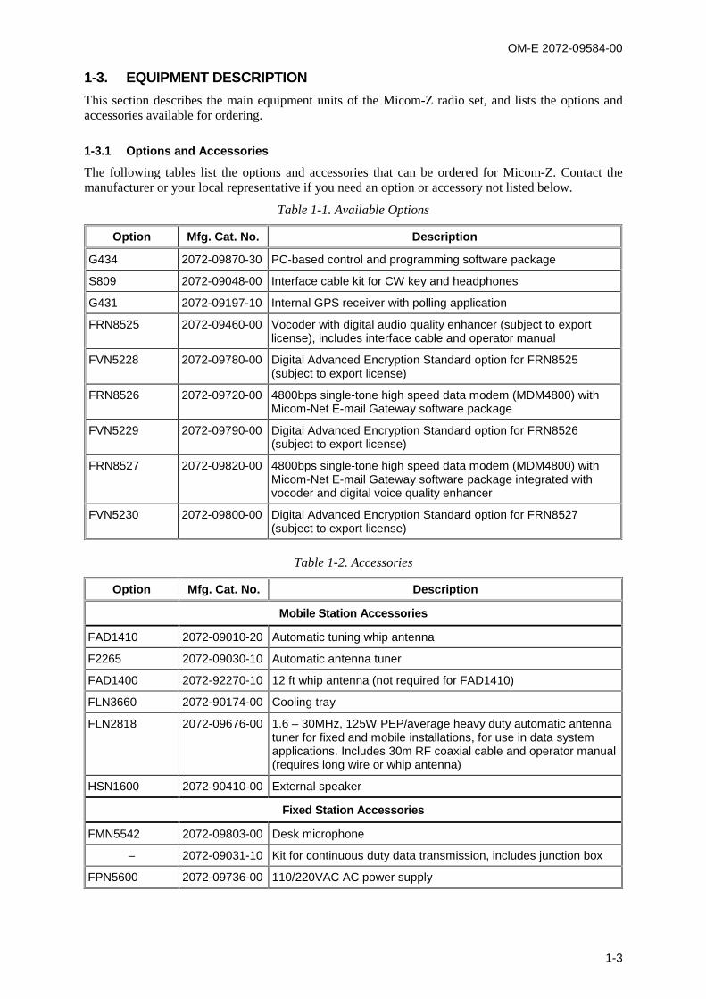
Table 1-1. Available Options
Option Mfg. Cat. No. Description
G434 2072-09870-30 PC-based control and programming software package
S809 2072-09048-00 Interface cable kit for CW key and headphones
G431 2072-09197-10 Internal GPS receiver with polling application
FRN8525 2072-09460-00 Vocoder with digital audio quality enhancer (subject to exportlicense), includes interface cable and operator manual
FVN5228 2072-09780-00 Digital Advanced Encryption Standard option for FRN8525(subject to export license)
FRN8526 2072-09720-00 4800bps single-tone high speed data modem (MDM4800) withMicom-Net E-mail Gateway software package
FVN5229 2072-09790-00 Digital Advanced Encryption Standard option for FRN8526(subject to export license)
FRN8527 2072-09820-00 4800bps single-tone high speed data modem (MDM4800) withMicom-Net E-mail Gateway software package integrated withvocoder and digital voice quality enhancer
FVN5230 2072-09800-00 Digital Advanced Encryption Standard option for FRN8527(subject to export license)
Table 1-2. Accessories
Option Mfg. Cat. No. Description
Mobile Station Accessories
FAD1410 2072-09010-20 Automatic tuning whip antenna
F2265 2072-09030-10 Automatic antenna tuner
FAD1400 2072-92270-10 12 ft whip antenna (not required for FAD1410)
FLN3660 2072-90174-00 Cooling tray
FLN2818 2072-09676-00 1.6 – 30MHz, 125W PEP/average heavy duty automatic antennatuner for fixed and mobile installations, for use in data systemapplications. Includes 30m RF coaxial cable and operator manual(requires long wire or whip antenna)
HSN1600 2072-90410-00 External speaker
Fixed Station Accessories
FMN5542 2072-09803-00 Desk microphone
– 2072-09031-10 Kit for continuous duty data transmission, includes junction box
FPN5600 2072-09736-00 110/220VAC AC power supply

OM-E 2072-09584-00
1-4
1-3.2 Micom-Z Transceiver
The Micom-Z transceiver is a complete HF/SSB receiver-transmitter capable of receiving andtransmitting voice, data, and continuous-wave (CW) telegraphy using upper-sideband (USB),lower-sideband (LSB), AME and pilot carrier modulation. High selectivity and a wide dynamic rangeensure clear, undisturbed signal reception.
The transmit power can be selected by the operator for optimum transmission performance (125 WPEP for maximum range; 100 W, 60 W or 25 W to reduce interference to nearby stations, anddecrease power dissipation).
The transmitter includes thermal protection. If, for any reason, the transmitter internal temperatureexceeds the maximum permitted temperature, the output power is automatically reduced to avoid anyfault due to excessive heat. Antenna mismatch protection is also included: if the antenna VSWR is toohigh, the transmit power will also be automatically reduced to avoid damage.
The transceiver nominal output impedance is 50 , and therefore it can be directly connected tobroadband antennas (dipoles, traveling wave antennas, delta and semi-delta antennas). For mobileservice using whip antennas, an external antenna tuning unit (ATU) is necessary. Suitable ATUs areavailable on order.
Micom-Z utilizes digital signal processing for implementing most of the receiver functions, e.g.,demodulation, narrow band filtering, automatic gain control, tunable notch filter, squelch, etc. Thedigital syllabic (speech identifier) squelch is activated whenever speech is identified, thus opening theaudio path. However, if speech is not received, the audio path is muted, thus preventing backgroundnoise from disturbing the operator.
In addition, Micom-Z uses ClearCom, a voice communication denoising algorithm that uses advanceddigital signal processing to remove background noise and dramatically enhance the received voiceclarity and intelligibility. This means that you can receive clear voice even with weak signals. Since allthe processing takes place within the receiving Micom-Z, ClearCom enhances any voice transmissionirrespective of the type of far radio set.
Moreover, ClearCom operates only on voice traffic, therefore it can be used even when using ALE orCCIR automatic link establishment protocols, and does not interfere in any way with data or vocodertransmissions. Therefore, you should enable ClearCom whenever the reception is weak: whencommunication conditions are good, ClearCom is not needed and will not make any difference.
NOTE
The ClearCom feature replaces the noise blanking feature, which iseffective only for reducing engine noises.
Micom-Z internal GPS receiver (optional) is a standard L1-band C/A SPS receiver that can providenavigation and time-of-day data. The minimum number of satellites that must be received is four, butthe receiver can simultaneously receive and process a larger number of satellites, thereby improvingthe positioning accuracy. When using the ALE or CCIR mode, the positioning data can be sent, uponrequest, to other radio sets.
The optional GPS receiver is supplied with an omnidirectional GPS antenna with magnetic mount,which can be located at up to 5 meters (15 feet) from Micom-Z.
Two dedicated connectors located on the rear panel provide a connection point for connecting dataequipment, and other user’s equipment.
The transceiver is powered from 13.8 VDC (nominal) (negative pole grounded). The transceiver canalso provide DC power to a compatible ATU, through the RF cable.
OM-E 2072-09584-00
1-5
1-3.3 Installation Accessories
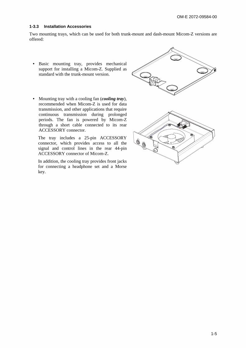
Two mounting trays, which can be used for both trunk-mount and dash-mount Micom-Z versions areoffered:
Basic mounting tray, provides mechanicalsupport for installing a Micom-Z. Supplied asstandard with the trunk-mount version.
Mounting tray with a cooling fan (cooling tray),recommended when Micom-Z is used for datatransmission, and other applications that requirecontinuous transmission during prolongedperiods. The fan is powered by Micom-Zthrough a short cable connected to its rearACCESSORY connector.
The tray includes a 25-pin ACCESSORYconnector, which provides access to all thesignal and control lines in the rear 44-pinACCESSORY connector of Micom-Z.
In addition, the cooling tray provides front jacksfor connecting a headphone set and a Morsekey.

OM-E 2072-09584-00
1-6
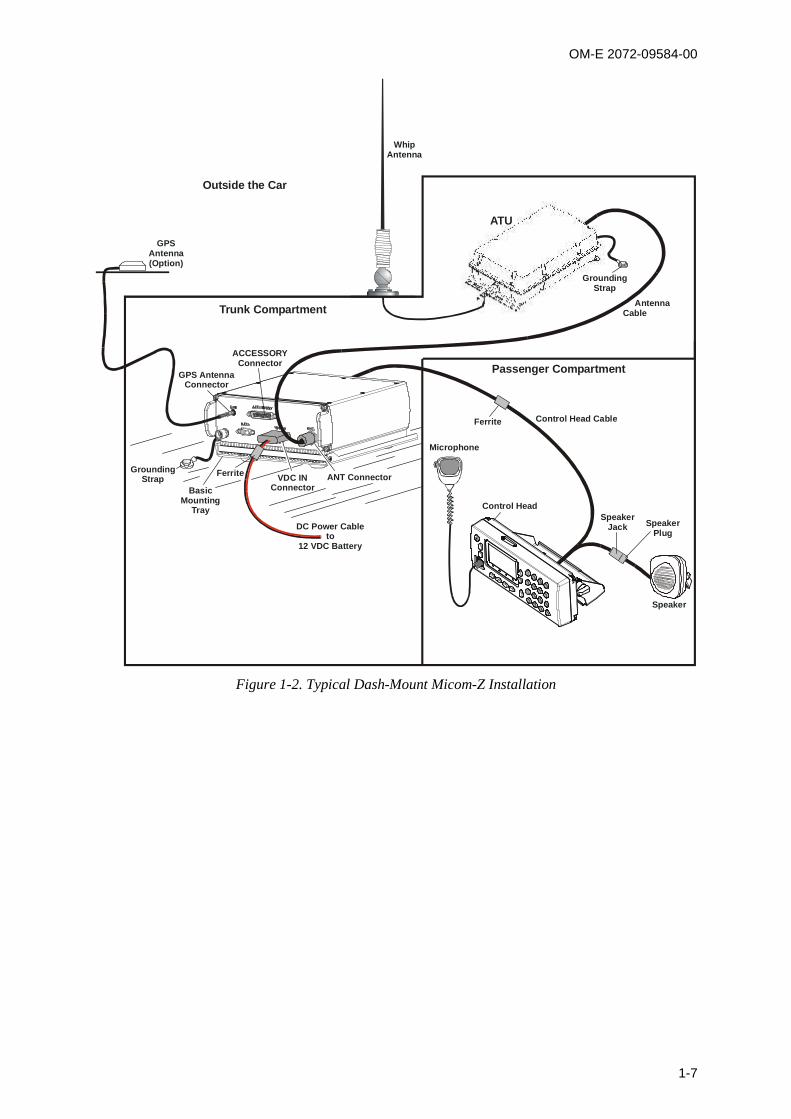
1-4. TYPICAL SYSTEM CONFIGURATIONSFigure 1-1 shows a typical trunk-mount Micom-Z installation, and Figure 1-2 shows a typicaldash-mount installation. Both figures illustrate installations with the ATU installed inside the vehicle.
ACCESSORYConnector
GPS AntennaConnector
GroundingStrap
FerriteBasic Mounting
TrayVDC IN
Connector
DC Power Cableto
12 VDC Battery
TrunkCompartment
PassengerCompartment
Outside the Car
GPSAntenna(Option)
ATU
ANT Connector
Microphone
AntennaCable
GroundingStrap
WhipAntenna
Figure 1-1. Typical Trunk-Mount Micom-Z Installation
OM-E 2072-09584-00
1-7
VDC INConnector
Trunk Compartment
Passenger Compartment
ATU
ANT Connector
Microphone
Control Head Cable
Control HeadSpeaker
Jack SpeakerPlug
DC Power Cableto
12 VDC Battery
ACCESSORYConnector
GPS AntennaConnector
GPSAntenna(Option)
GroundingStrap
Outside the Car
WhipAntenna
BasicMounting
Tray
Ferrite
Ferrite
AntennaCable
GroundingStrap
Speaker
Figure 1-2. Typical Dash-Mount Micom-Z Installation
OM-E 2072-09584-00
1-8
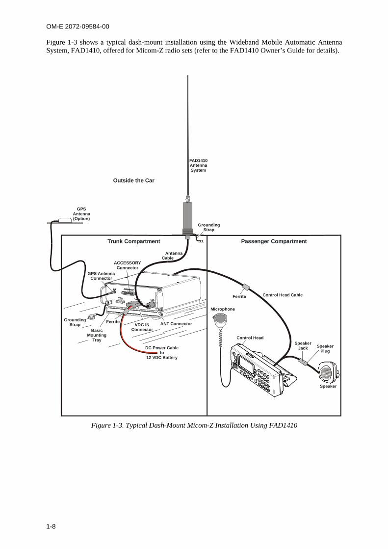
Figure 1-3 shows a typical dash-mount installation using the Wideband Mobile Automatic AntennaSystem, FAD1410, offered for Micom-Z radio sets (refer to the FAD1410 Owner’s Guide for details).
VDC INConnector
Trunk Compartment Passenger Compartment
ANT Connector
Microphone
Control Head Cable
Control Head
AntennaCable
DC Power Cableto
12 VDC Battery
ACCESSORYConnector
GPS AntennaConnector
GroundingStrap
GPSAntenna(Option)
GroundingStrap
Outside the Car
FAD1410AntennaSystem
BasicMounting
Tray
Ferrite
Ferrite
Speaker
SpeakerJack Speaker
Plug
Figure 1-3. Typical Dash-Mount Micom-Z Installation Using FAD1410
OM-E 2072-09584-00
1-9
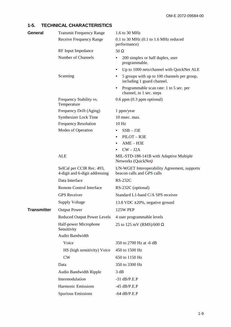
1-5. TECHNICAL CHARACTERISTICSGeneral Transmit Frequency Range 1.6 to 30 MHz
Receive Frequency Range 0.1 to 30 MHz (0.1 to 1.6 MHz reducedperformance)
RF Input Impedance 50 Number of Channels 200 simplex or half duplex, user
programmable.
Up to 1000 nets/channel with QuickNet ALE
Scanning 5 groups with up to 100 channels per group,including 1 guard channel.
Programmable scan rate: 1 to 5 sec. perchannel, in 1 sec. steps
Frequency Stability vs.Temperature
0.6 ppm (0.3 ppm optional)
Frequency Drift (Aging) 1 ppm/year
Synthesizer Lock Time 10 msec. max.
Frequency Resolution 10 Hz
Modes of Operation SSB – J3E
PILOT – R3E
AME – H3E
CW – J2A
ALE MIL-STD-188-141B with Adaptive MultipleNetworks (QuickNet)
SelCal per CCIR Rec. 493,4-digit and 6-digit addressing
UN-WGET Interoperability Agreement, supportsbeacon calls and GPS calls
Data Interface RS-232C
Remote Control Interface RS-232C (optional)
GPS Receiver Standard L1-band C/A SPS receiver
Supply Voltage 13.8 VDC 20%, negative ground
Transmitter Output Power 125W PEP
Reduced Output Power Levels 4 user programmable levels
Half-power MicrophoneSensitivity
25 to 125 mV (RMS)/600
Audio Bandwidth
Voice 350 to 2700 Hz at -6 dB
HS (high sensitivity) Voice 450 to 1500 Hz
CW 650 to 1150 Hz
Data 350 to 3300 Hz
Audio Bandwidth Ripple 3 dB
Intermodulation -31 dB/P.E.P
Harmonic Emissions -45 dB/P.E.P
Spurious Emissions -64 dB/P.E.P
OM-E 2072-09584-00
1-10
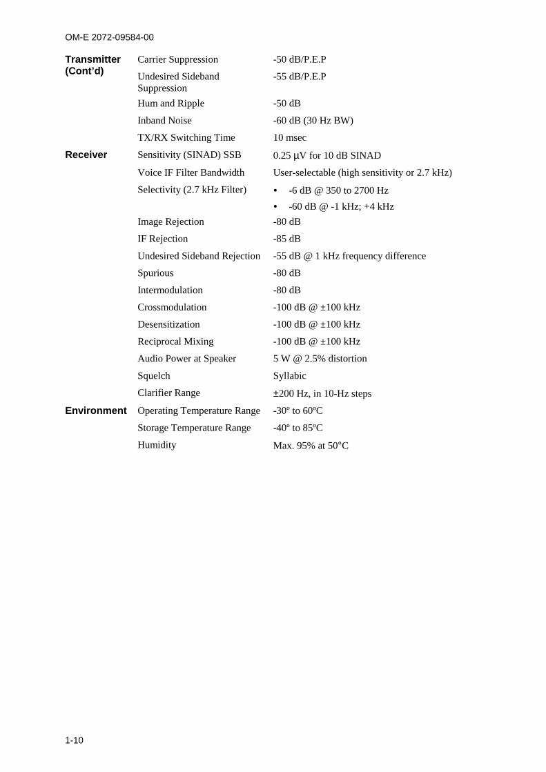
Transmitter(Cont’d)
Carrier Suppression -50 dB/P.E.P
Undesired SidebandSuppression
-55 dB/P.E.P
Hum and Ripple -50 dB
Inband Noise -60 dB (30 Hz BW)
TX/RX Switching Time 10 msec
Receiver Sensitivity (SINAD) SSB 0.25 V for 10 dB SINAD
Voice IF Filter Bandwidth User-selectable (high sensitivity or 2.7 kHz)
Selectivity (2.7 kHz Filter) -6 dB @ 350 to 2700 Hz
-60 dB @ -1 kHz; +4 kHz
Image Rejection -80 dB
IF Rejection -85 dB
Undesired Sideband Rejection -55 dB @ 1 kHz frequency difference
Spurious -80 dB
Intermodulation -80 dB
Crossmodulation -100 dB @ ±100 kHz
Desensitization -100 dB @ ±100 kHz
Reciprocal Mixing -100 dB @ ±100 kHz
Audio Power at Speaker 5 W @ 2.5% distortion
Squelch Syllabic
Clarifier Range 200 Hz, in 10-Hz steps
Environment Operating Temperature Range -30º to 60ºC
Storage Temperature Range -40º to 85ºC
Humidity Max. 95% at 50C
OM-E 2072-09584-00
2-1
CHAPTER 2
OPERATING PROCEDURES
2-1. SCOPEIn this Chapter, you can find …
information needed to familiarize with the equipment panels – para. 2-2
procedures for using the Micom-Z keypad and display to perform any desired task – para. 2-3,2-4, and para. 2-10, 2-11
how to start using a radio ready for operation (i.e., a radio installed in accordance with Chapter 3and programmed in accordance with Chapter 4) – para. 2-5
specific operating procedures for each main operating mode of the radio:
Channel mode – para. 2-6
Frequency mode – para. 2-7
Scan mode – para. 2-8
ALE mode – para. 2-12
CCIR mode – para. 2-13.
procedures for using the GPS receiver – para. 2-9.
2-2. FAMILIARIZATION WITH EQUIPMENT PANELS
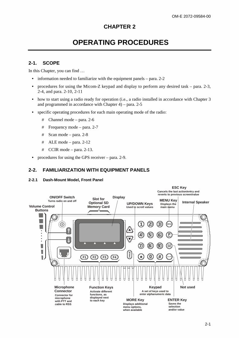
2-2.1 Dash-Mount Model, Front Panel
F4MOREF3F2F1
1
*
DMENU
ALMGPS
Esc
EF
AB
C2
JK
L5
TU
V8
NO
M6
WXYZ9
3
0 #
GHI4 P
PQS7R
Slot forOptional SD
Memory Card
ON/OFF SwitchTurns radio on and off
UP/DOWN KeysUsed to scroll values
Display
KeypadA set of keys used to
enter alphanumeric data
Saves theselectionand/or value
ENTER Key
Not used
Cancels the last action/entry andreverts to previous screen/value
ESC Key
Displays themain menu
MENU Key Internal Speaker
Function KeysActivate differentfunctions, asdisplayed nextto each key MORE Key
Displays additionalmenu options,when available
MicrophoneConnectorConnector formicrophonewith PTT andcable to RSS
Volume ControlButtons
OM-E 2072-09584-00
2-2
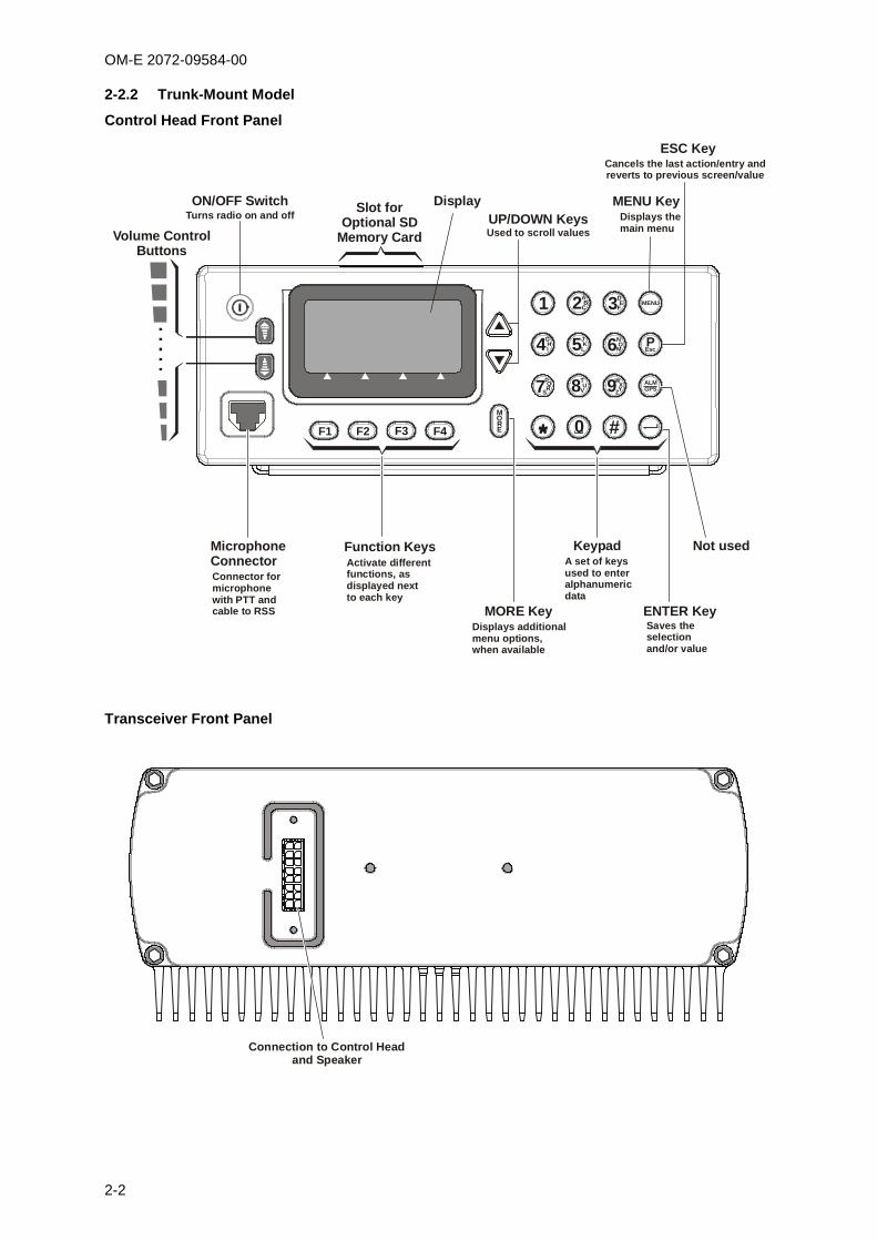
2-2.2 Trunk-Mount Model
Control Head Front Panel
1
*
DMENU
ALMGPS
Esc
EF
AB
C2
JK
L5
TU
V8
NO
M6
WXYZ9
3
0 #
GHI4 P
PQS7R
MOREF4F3F2F1 *
Slot forOptional SD
Memory Card
ON/OFF SwitchTurns radio on and off UP/DOWN Keys
Used to scroll values
Display
KeypadA set of keysused to enteralphanumericdata
Saves theselectionand/or value
ENTER Key
Not used
Cancels the last action/entry andreverts to previous screen/value
ESC Key
Displays themain menu
MENU Key
Function KeysActivate differentfunctions, asdisplayed nextto each key
MORE KeyDisplays additionalmenu options,when available
MicrophoneConnectorConnector formicrophonewith PTT andcable to RSS
Volume ControlButtons
Transceiver Front Panel
Connection to Control Headand Speaker
OM-E 2072-09584-00
2-3
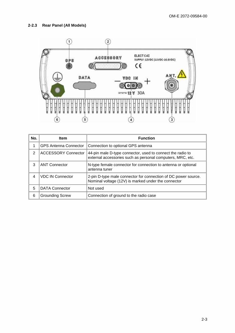
2-2.3 Rear Panel (All Models)
No. Item Function
1 GPS Antenna Connector Connection to optional GPS antenna
2 ACCESSORY Connector 44-pin male D-type connector, used to connect the radio toexternal accessories such as personal computers, MRC, etc.
3 ANT Connector N-type female connector for connection to antenna or optionalantenna tuner
4 VDC IN Connector 2-pin D-type male connector for connection of DC power source.Nominal voltage (12V) is marked under the connector
5 DATA Connector Not used
6 Grounding Screw Connection of ground to the radio case

OM-E 2072-09584-00
2-4
2-3. FAMILIARIZATION WITH MICOM-Z OPERATING PROCEDURESThis section provides general procedures that will help you start using your radio and get the most ofits advanced features. Most of the activities that can be performed by you (selection of operating mode,programming, testing, etc.) are done using the keypad together with the navigation and function keys,and the front panel display.
To simplify operation, Micom-Z function keys operate as soft keys and therefore they permit youcontrol the radio simply and efficiently, using a menu-driven mode that guides you and helps you makethe required selections. “Menu-driven” simply means that whenever you must select a parameter, anoperating mode, etc., you select it from a list of allowed values displayed on the front panel display,thereby reducing the chance of error:
To make a selection, you use navigation keys to reach the desired parameter value or action, and
then confirm the selection by pressing the ENTER key.
To go back to previous options, or cancel the current selection or action, press the ESC EscP key.
2-3.1 Display Functions
2-3.1.1 Display Organization
CH 1F 2,000.00
BAND SQ
1
2
4
5
3
No. Designation Description
1 Mode Indicator Indicates the current working mode (e.g., channel, frequency, ALE,etc.) or the action being performed (e.g., programming, testing, etc.)
2 Work Area Displays information on the current working mode, the main operatingparameters, etc. It also includes icons that identify the active options,and status
3 Level Indicator In the transmit mode, displays the relative transmit power.
In the receive mode, displays the relative received signal strength
4 Tx Bar Appears when the radio is transmitting
5 Options Display Bar Displays a list of options you can select, by pressing the correspondingfunction key, in the current working mode
2-3.1.2 RF Level Indications
Indication Meaning
Strong received signal
Weak received signal
Received RF signal strength indication, displayed when the radio is inthe receive mode. The number of bars provides a relative indication,which may fluctuate as a result of fading, etc.
Full transmit powerRelative transmit power
Low transmit powerReflected power
Transmit bar, appears when the radio is switched to the transmit mode(for example, when the PTT is pressed). Its length indicates themaximum radio transmit power in the selected mode (MAX, HIGH, MEDor LO). The number of bars indicates the instantaneous relative transmitoutput power, and therefore it fluctuates as a result of modulation. Therelative reflected power is indicated by the base line: its length indicatesthe fraction of power reflected because of antenna VSWR (the lengthshould be small relative to the total height of the transmit bar, which isproportional to the forward power)
OM-E 2072-09584-00
2-5
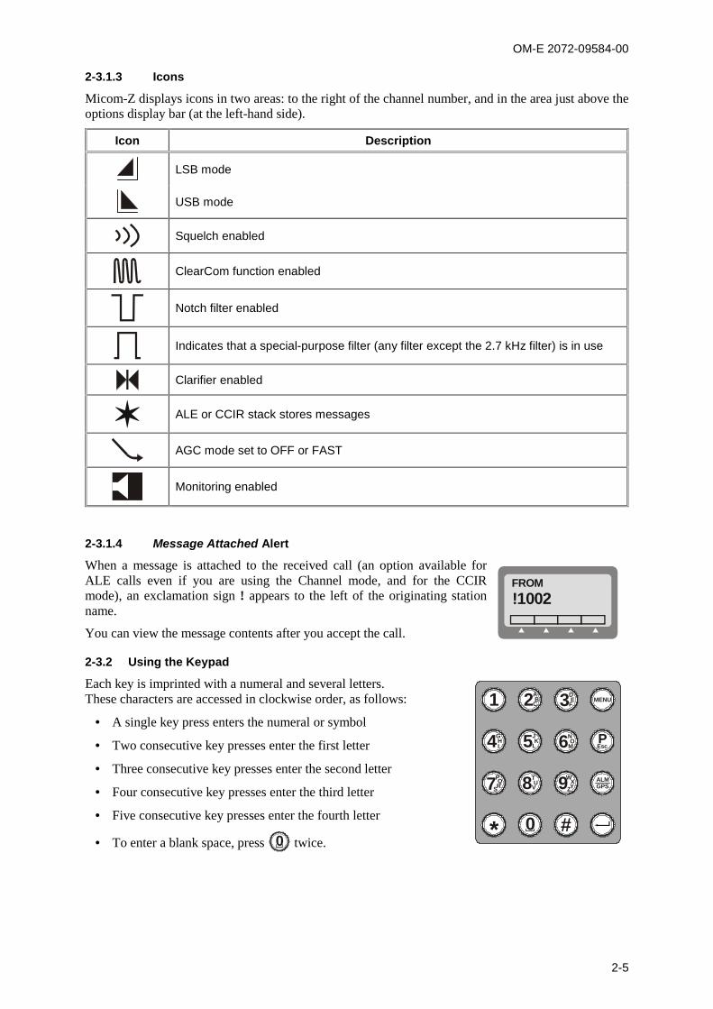
2-3.1.3 Icons
Micom-Z displays icons in two areas: to the right of the channel number, and in the area just above theoptions display bar (at the left-hand side).
Icon Description
LSB mode
USB mode
Squelch enabled
ClearCom function enabled
Notch filter enabled
Indicates that a special-purpose filter (any filter except the 2.7 kHz filter) is in use
Clarifier enabled
ALE or CCIR stack stores messages
AGC mode set to OFF or FAST
Monitoring enabled
2-3.1.4 Message Attached Alert
When a message is attached to the received call (an option available forALE calls even if you are using the Channel mode, and for the CCIRmode), an exclamation sign ! appears to the left of the originating stationname.
You can view the message contents after you accept the call.
FROM!1002
2-3.2 Using the Keypad
Each key is imprinted with a numeral and several letters.These characters are accessed in clockwise order, as follows:
A single key press enters the numeral or symbol
Two consecutive key presses enter the first letter
Three consecutive key presses enter the second letter
Four consecutive key presses enter the third letter
Five consecutive key presses enter the fourth letter
To enter a blank space, press 0 twice.
1
*
DMENU
ALMGPS
Esc
EF
AB
C2
JK
L5
TU
V8
NO
M6
WXYZ9
3
0 #
GHI4 P
PQS7R
OM-E 2072-09584-00
2-6
When entering frequencies, use the * key as a decimal point, if needed. In the ALE mode, the *key is also used to enter a wild-card character (? or @).
To enter the ampersand @ symbol, press the # key twice.
Example: To enter a number in a field, or edit (change) the number, you type the desired digits on thekeypad.
Example: To enter an alphanumeric string in a field, or edit a string, you type the desiredalphanumeric character by pressing the appropriate key several times in sequence. For example, toenter “MIKE 01”:
Press NO
M6 twice (for the letter M).
Press GHI4 four times (for the letter I).
Press JK
L5 three times (for the letter K).
Press DE
F3 three times (for the letter E).
Press 0 twice (for the blank space).
Press 0 once (for the numeral 0).
Press 1 once (for the numeral 1).
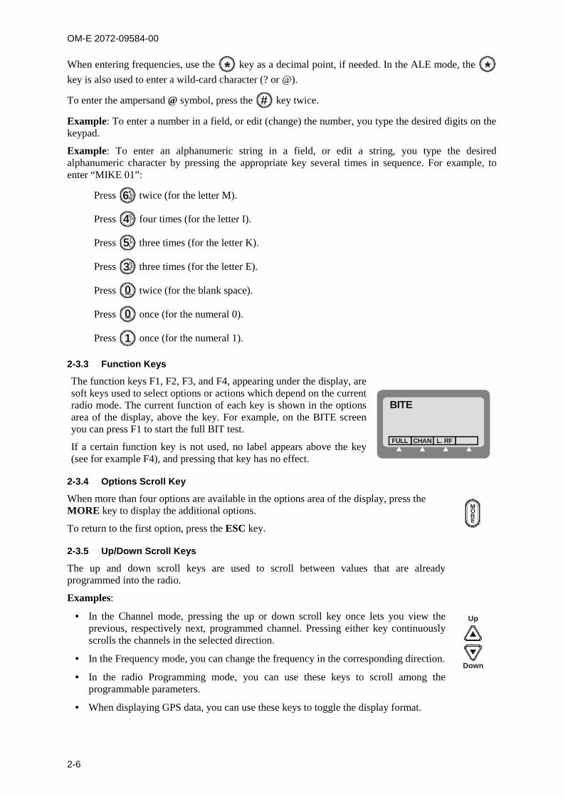
2-3.3 Function Keys
The function keys F1, F2, F3, and F4, appearing under the display, aresoft keys used to select options or actions which depend on the currentradio mode. The current function of each key is shown in the optionsarea of the display, above the key. For example, on the BITE screenyou can press F1 to start the full BIT test.
If a certain function key is not used, no label appears above the key(see for example F4), and pressing that key has no effect.
BITE
CHANFULL L. RF
2-3.4 Options Scroll Key
When more than four options are available in the options area of the display, press theMORE key to display the additional options.
To return to the first option, press the ESC key.
MORE
2-3.5 Up/Down Scroll Keys
The up and down scroll keys are used to scroll between values that are alreadyprogrammed into the radio.
Examples:
In the Channel mode, pressing the up or down scroll key once lets you view theprevious, respectively next, programmed channel. Pressing either key continuouslyscrolls the channels in the selected direction.
In the Frequency mode, you can change the frequency in the corresponding direction.
In the radio Programming mode, you can use these keys to scroll among theprogrammable parameters.
When displaying GPS data, you can use these keys to toggle the display format.
Up
Down

OM-E 2072-09584-00
2-7
2-3.6 Selection from List of Predetermined Values
When the parameter you want to change can assume only one of several predetermined values, youselect the desired value by pressing function keys:
F1 enters the lowest possible value, or OFF
F4 enters the highest possible value
F2 and F3 increments, respectively, decrements, the value. When you reach either end, thecorresponding key disappears.
You cannot use the keypad to enter a value for such parameters.
2-3.7 Toggle Mode
When the function being set can only be toggled on or off, one function key will be marked YES andanother NO.
To expedite turning on and off often-used functions (for example, turn the squelch on or off) only onekey is used. In this case, just press the key assigned to the function to be toggled: the new state isshown for a few seconds, and then disappears as it takes effect immediately.
2-3.8 Alphanumeric Edit Mode
When you need to enter an alphanumeric string in a field, or edit a string, you select each desiredalphanumeric character on the keypad as explained above. A blinking cursor _ indicates the locationbeing edited.
In addition, the following edit function keys are available:
SAVE Saves editing changes (equivalent to pressing the ENTER key).
Used to move the cursor backwards and forwards. When you reach either end, thecorresponding key disappears.
CLR Pressing this key momentarily erases the digit/letter at which the cursor is presentlylocated, and shifts the entire field one place to the left.
Pressing this key continuously clears the entire field.
2-3.9 Numeric Edit Mode
When you need to enter a number in a field, or edit the number, you type the desired digits on thekeypad. A blinking cursor _ indicates the location being edited.
In addition, the following edit function keys are available:
BACK Erases the last digit.
CLR Erases all newly entered digits and restores the original value.
2-3.9.1 View Mode
When the string to be displayed is longer than the number of characters that fit in one line (forinstance, with long addresses or messages), the view mode enables scrolling to the rest of the string.
The view mode is indicated by the symbol next to one of the function keys.
When you press , the key functions change:
HOME Scrolls to display the first character of the string.
Scroll one character to the left or right, respectively. If you press either keycontinuously, the scrolling continues at a rate of four characters per second.
END Scrolls to display the last character of the string.
When you reach the beginning of the string, the HOME and function keys disappear, whereaswhen you reach the end of the string, the and END function keys disappear.

OM-E 2072-09584-00
2-8
2-3.10 Audible Indications
The user can configure the radio to generate audible tones to indicate events related to the radiooperating conditions. The tone volume, low or high, may also be set using the MRC, or byprogramming from the front panel.
Event Description
Valid key pressing Beep sounds when a key is pressed, to indicate that the key pressing has beenaccepted. No beep – no action.
PTT release A beep sounds on the remote radio to indicate that the local PTT button hasbeen released.
ALE alerts During ALE operation, beeps alert you to events you should be aware of, e.g.,link establishment/disconnection, etc.

OM-E 2072-09584-00
2-9
2-4. MENU STRUCTUREThe menu is used to select and control what you want your radio to do.
2-4.1 Displaying the Main Menu
To display the menu:
1. Press MENU to display the first part of the Menu screen.You can press the MENU key at any time during any sequence ofoperations: that sequence is then discontinued and the menu screen isimmediately displayed.
MENU
FREQCHAN CCIR BIT
NOTE
The menu structure depends on the operating mode selectedby the user. For example, when the CCIR function is not used,the third item is either ALE or SCAN.
2. Press MORE to scroll to the second part of the Menu screen.MENU
PROGLOCK PSW DIM
3. To select any item, press the function key next to it.
To exit the menu and return to regular radio operations (e.g., CHAN or FREQ):
1. Press the ESC key. The deeper you are in the menu, the more times you need to press ESC.
2-4.2 What you can Select on the Main Menu
DIM
1234
LEVEL0 1 2
CHAN FREQ
FULLCHANL.RF
BIT
LOCKPSW
LOCK PROG
PSWOLD
PSW
SMPXDPLXRXOTXO
SCANCALL
CCIR SCANRAD
CCIR
ABCDE
MORE
ALE
NET
Main Menu
ALE or
or or
Figure 2-1. Main Menu

OM-E 2072-09584-00
2-10
Use the following description with Figure 2-1, which shows the details of the main menu.
Menu item ... and its purposeCHAN Channel mode: the radio uses a set of preset parameters. Up to 200 sets of
parameters can be defined and stored in the Micom-Z, where each set is assigned achannel number (1 to 200). You can use Figure 2-2 to find details on theselections available on the CHAN menu.
FREQ Frequency mode: you can select manually the frequency (free tune mode) and theother parameters to be used. You can use Figure 2-3 to find details on theselections available on the FREQ menu.
ALE ALE mode: when you want to call other radio, the radio automatically sets up alink on the best free frequency that can be found. You can also call specific radiosets, a group of radio, or broadcast to all the radio sets. The sets of parametersneeded for this operation mode are stored under net numbers (1 to 20), the radiosets are identified by addresses stored by the radio in a directory supporting up to100 addresses.
SCAN SCAN mode: when neither the ALE, nor the CCIR mode, is used, you can definea set of channels to be scanned before starting a call. The scan parameters arealways loaded by the MRC together with the other operational parameters, andcannot be changed using the Micom-Z panel.
CCIR CCIR mode: mode that supports functions similar to ALE, except that it uses adifferent addressing scheme.
BIT BIT mode: lets you check that the Micom-Z is OK.
LOCK Lock the radio to prevent unauthorized use. To lock and unlock, you enter apassword.
PROG Programming mode: lets you program (select and store) the required parameters.Refer to Chapter 4 for details on the selections available on the PROG menu.
PSW Used to change the password.
DIM Used to adjust LCD lighting.
2-4.3 Notational Convention
In this manual, the following convention is used to simplify the description of the steps you need tocarry out actions using the keys and the LCD:
When a procedure begins with a sequence of steps, that sequence is represented in anabbreviated format, with the > symbol indicating the next key to be pressed.
For instance, the following represents a sequence of steps that involves five keypressings: MENU > MORE > PROG > RAD > CHAN.
OM-E 2072-09584-00
2-11
2-5. GETTING STARTEDThis section provides basic operating instructions: it covers issues such as turning the radio on and off,receiving and transmitting, selecting a channel or a frequency, etc.
NOTES
The information needed to use Micom-Z in the ALE mode appearsin para. 2-12.
The information needed to use Micom-Z in the CCIR modeappears in para. 2-13.
The information needed to use the Micom-Z GPS receiver appearsin para. 2-9.
You can use these instructions to start using your Micom-Z radio. To become familiar with all theradio capabilities and features, refer to the following sections. In most cases, the radio reaches youafter being configured for use in your radio net. However, if you need to make changes, refer toChapter 4.
2-5.1 Turning the Radio On and Off
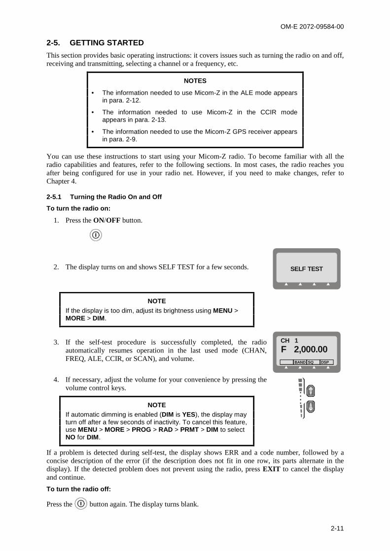
To turn the radio on:
1. Press the ON/OFF button.
2. The display turns on and shows SELF TEST for a few seconds. SELF TEST
NOTEIf the display is too dim, adjust its brightness using MENU >MORE > DIM.
3. If the self-test procedure is successfully completed, the radioautomatically resumes operation in the last used mode (CHAN,FREQ, ALE, CCIR, or SCAN), and volume.
CH 1F 2,000.00
BAND SQ DSP
4. If necessary, adjust the volume for your convenience by pressing thevolume control keys.
NOTEIf automatic dimming is enabled (DIM is YES), the display mayturn off after a few seconds of inactivity. To cancel this feature,use MENU > MORE > PROG > RAD > PRMT > DIM to selectNO for DIM.
....
If a problem is detected during self-test, the display shows ERR and a code number, followed by aconcise description of the error (if the description does not fit in one row, its parts alternate in thedisplay). If the detected problem does not prevent using the radio, press EXIT to cancel the displayand continue.
To turn the radio off:
Press the button again. The display turns blank.
OM-E 2072-09584-00
2-12
2-5.2 Transmitting and Receiving
NOTES
When transmitting, the RF output of the radio must be connectedto an antenna installed as explained in the Installation chapter (formaintenance, you may also connect to a dummy load of suitablepower rating). Do not attempt to transmit when the antenna is notconnected, or when the antenna or any cable leading to it isphysically damaged.
If the antenna system is equipped with an automatic antenna tunerand the tuner is enabled, the radio will automatically tune theantenna tuner. In the Channel mode, pressing the ENTER keyautomatically retunes the antenna.
To transmit a voice message:
Press and hold down the Push-to-Talk (PTT) button of the microphone, and speak slowly and clearlyafter the channel is clear.
You should hear a sidetone, which verifies that your radio transmits normally.
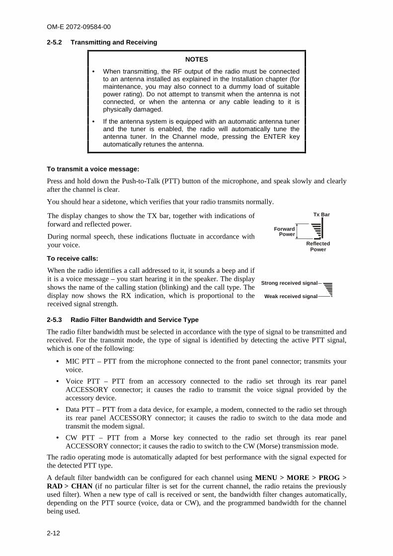
The display changes to show the TX bar, together with indications offorward and reflected power.
During normal speech, these indications fluctuate in accordance withyour voice.
Tx Bar
ForwardPower
ReflectedPower
To receive calls:
When the radio identifies a call addressed to it, it sounds a beep and ifit is a voice message – you start hearing it in the speaker. The displayshows the name of the calling station (blinking) and the call type. Thedisplay now shows the RX indication, which is proportional to thereceived signal strength.
Strong received signal
Weak received signal
2-5.3 Radio Filter Bandwidth and Service Type
The radio filter bandwidth must be selected in accordance with the type of signal to be transmitted andreceived. For the transmit mode, the type of signal is identified by detecting the active PTT signal,which is one of the following:
MIC PTT – PTT from the microphone connected to the front panel connector; transmits yourvoice.
Voice PTT – PTT from an accessory connected to the radio set through its rear panelACCESSORY connector; it causes the radio to transmit the voice signal provided by theaccessory device.
Data PTT – PTT from a data device, for example, a modem, connected to the radio set throughits rear panel ACCESSORY connector; it causes the radio to switch to the data mode andtransmit the modem signal.
CW PTT – PTT from a Morse key connected to the radio set through its rear panelACCESSORY connector; it causes the radio to switch to the CW (Morse) transmission mode.
The radio operating mode is automatically adapted for best performance with the signal expected forthe detected PTT type.
A default filter bandwidth can be configured for each channel using MENU > MORE > PROG >RAD > CHAN (if no particular filter is set for the current channel, the radio retains the previouslyused filter). When a new type of call is received or sent, the bandwidth filter changes automatically,depending on the PTT source (voice, data or CW), and the programmed bandwidth for the channelbeing used.

OM-E 2072-09584-00
2-13
Bandwidth set to: Service type: Filter changes after:HS Data First data PTT
2.7 kHz Voice First microphone or voice PTT
3.0 kHz Data First data PTT
3.3 kHz High speed data First data PTT
CW Morse First CW PTT
LSM Low speed data First data PTT
NOTE
When the filter bandwidth is set to CW, the following CW filterbandwidths can be configured in the Programming mode using MENU> MORE > PROG > RAD > PRMT: 0.25, 0.5 or 0.8 (kHz).
2-6. USING THE CHANNEL MODEThe Channel mode is used to operate on a channel already programmed in the Micom-Z.
The following sections describe how to use the Channel mode.
2-6.1 Selecting the Channel Mode
In general, the Micom-Z automatically enters the Channel mode when turned on, and starts using thelast used channel.
If not, use the Menu screen to select the Channel mode: this is the first item on the menu you see whenyou press MENU.
To enter the Channel mode:
1. Press MENU to display the Menu screen.
MENU
FREQCHAN CCIR BIT
2. Press CHAN.
The last active channel flashes in the display.
CH 1
BAND SQ DSP
3. Press ENTER to confirm your choice, or select another channel asexplained in the Choosing a Different Channel section (para. 2-6.3).
CH 1F 2,000.00
BAND SQ DSP

OM-E 2072-09584-00
2-14
2-6.2 Channel Mode Options
In the Channel mode, you can operate a variety of functions and options which can help eliminatenoise or otherwise assist reception and/or transmission.
NOTE
The changing of the channel options is temporary. When you changethe currently used channel, all the current options will be lost andreplaced by the values configured for the newly selected channel.
The structure of the CHAN menu is shown in Figure 2-2.
CHAN
BAND DSP PWR
LOWMEDHIGHMAX
CLAR
ONOFF
SQ
ONOFF
MODE AGC
SLOWFASTOFF
BW
HS2.73.03.3LSMCW
RCLV
LSBUSB
SSBAMEPLT
ONOFF
ONOFF
-200
OFF
+200
........
........
CLIP
CC
ATTN
....
NF
For ALE modeMORE
Main Menu
MORE
MORE
SENDEDITCHAN<- >
ALL
NET
GRP
ANY
WILD
SELF SENDCHAN
SENDPAGECHANSEL
SENDPAGECHANSEL
SENDPAGECHANSEL
SENDPAGECHAN
SENDPAGEGLOBSEL
MULT
MORE
CALL
SENDPAGECHAN
MON
ONOFF
GPS
(Disabled for CCIR)
Figure 2-2. Channel (CHAN) Menu

OM-E 2072-09584-00
2-15
The following table presents a concise description of the options available in the Channel mode.
Option Description
TXM Press to switch to the channel transmit frequency (appears only when using a duplex, orTX-only channel – see Figure 2-3). After releasing the PTT, the radio returns to the receivefrequency.
BAND Toggles between upper sideband (USB) and lower sideband (LSB).
SQ Toggles the squelch on/off. Always select OFF for CW operation.
DSP Accesses the Digital Signal Processing menu, which includes the following options:
CLAR Enables to control the clarifier (off/lower frequency/higher frequency). Thefunction key is not available for TXO (transmit only) channels.
NF Enables to control the notch filter (off/lower frequency/higher frequency).The function key is not available for TXO (transmit only) channels, and inthe CCIR mode.
CLIP Toggles the clipper on/off.
CC Toggles the ClearCom function on/off.
ATTN Toggles the attenuator on/off.
PWR Selects the transmit power level: LOW – 25W; MED – 60W; HIGH – 100W; MAX – 125W.
MODE Selects the operation mode: SSB – single sideband AME – amplitude modulation equivalent PLT – single sideband with pilot signal.
AGC Controls the automatic gain control function (fast/slow/off).
BW Selects the filter bandwidth: HS – high sensitivity filter (450 to 1500 Hz) for best voice communication under
marginal conditions 2.7 – 300 to 2700 Hz 3.0 – 300 to 3000 Hz 3.3 – 300 to 3300 Hz. Always select this bandwidth for data transmission LSM – bandwidth optimized for use with low speed modems (1450 to 1950 Hz) CW (Continuous Wave or Morse operation). The bandwidth used in this case is
selected by MENU > PROG > RAD > PRMT > CW.
RCLV Displays the receive level. The RCLV item appears only if the received signal level displayis not permanently enabled using MENU > PROG > RAD > PRMT > RCLV.
GPS Displays the GPS data. Refer to para. 2-9 for details.
NOTE
When ALE or CCIR is active, the following options appear:
CALL – initiates an ALE or CCIR call.
PAGE – displays the stacked received messages.
MON – enables/disables the speaker during link establishment.
For a description of these options, refer to para. 2-12 (ALE mode) orpara. 2-13 (CCIR mode).
OM-E 2072-09584-00
2-16
2-6.3 Choosing a Different Channel
To choose a channel:
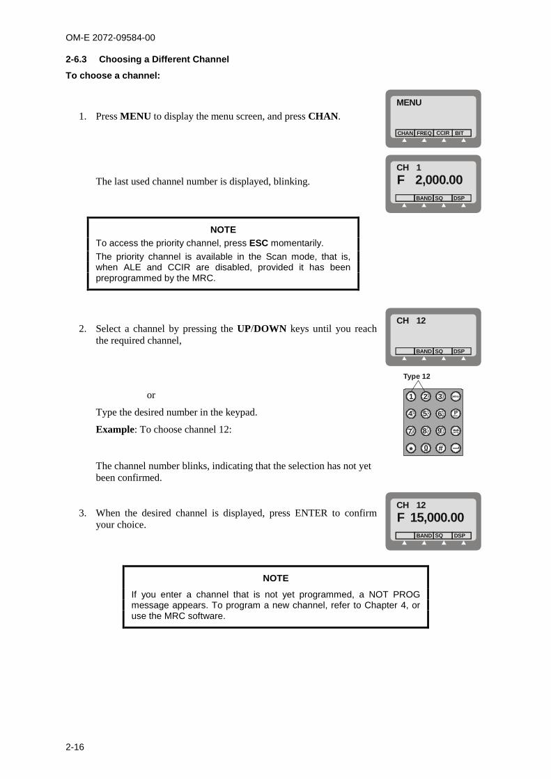
1. Press MENU to display the menu screen, and press CHAN.MENU
FREQCHAN CCIR BIT
The last used channel number is displayed, blinking.CH 1F 2,000.00
BAND SQ DSP
NOTETo access the priority channel, press ESC momentarily.The priority channel is available in the Scan mode, that is,when ALE and CCIR are disabled, provided it has beenpreprogrammed by the MRC.
2. Select a channel by pressing the UP/DOWN keys until you reachthe required channel,
CH 12
BAND SQ DSP
or
Type the desired number in the keypad.
Example: To choose channel 12:
1
*
ABC2
JKL5
TUV8
NO
M6
WXYZ9
DEF3
0 #
MENU
GHI4 Esc
P
ALMGPS
PQS7R
Type 12
The channel number blinks, indicating that the selection has not yetbeen confirmed.
3. When the desired channel is displayed, press ENTER to confirmyour choice.
CH 12F 15,000.00
BAND SQ DSP
NOTE
If you enter a channel that is not yet programmed, a NOT PROGmessage appears. To program a new channel, refer to Chapter 4, oruse the MRC software.

OM-E 2072-09584-00
2-17
2-7. USING THE FREQUENCY MODEThe Frequency mode enables you to select freely the receive and transmit frequencies. You can selectthe operating frequency type, change the frequency being used, and operate a variety of functions andoptions to assist transmission and reception. You can also store the frequency in a channel of yourchoice.
There are four types of operating frequencies:
SMPX (Simplex Frequency): the same frequency is used for both transmission and reception.
DPLX (Duplex Frequency): the radio transmits on one frequency and receives on a differentfrequency.
RXO (Receive Only Frequency): defines a frequency for reception only. You cannot transmiton a frequency configured as RXO.
TXO (Transmit Only Frequency): defines a frequency for transmission only. You will notreceive on a frequency configured as TXO.
The supported frequency ranges are:
Reception: 100 kHz to 30 MHz.
Transmission: 1.6 to 30 MHz.
NOTE
The ALE, CCIR, and Frequency modes are mutually exclusive.
2-7.1 Frequency Mode Options
In the Frequency mode, you can operate a variety of functions and options which can eliminate noiseor otherwise assist reception and/or transmission.
The structure of the FREQ menu is shown in Figure 2-3.
BAND DSP PWR
CLAR
ONOFF
SQ
ONOFF
MODE AGC
SLOWFASTOFF
BW
HS2.73.03.3LSMCW
RCLV STOR
LSBUSB
SSBAMEPLT
ONOFF
ONOFF
-200
OFF
+200
........
........
CLIP
CC
ATTN
....
NF
T/R A/B
A/BA=B
LOWMEDHIGHMAX
SMPXDPLXRXOTXO
FREQ
MORE
Main Menu
MORE
MORE
MORE
GPS
Figure 2-3. FREQ (Frequency) Menu

OM-E 2072-09584-00
2-18
The following table presents a concise description of the options available in the Frequency mode.
Option Description
T/R Selects the transmit and receive frequencies and frequency type.
BAND Toggles between upper sideband (USB) and lower sideband (LSB).
SQ Toggles the squelch on/off. Always select OFF for CW operation.
DSP Accesses the Digital Signal Processing menu, which includes the following options:
CLAR Enables to control the clarifier (off/lower frequency/higher frequency). Thefunction key is not available for TXO (transmit only) channels.
NF Enables to control the notch filter (off/lower frequency/higher frequency).The function key is not available for TXO (transmit only) channels, and inthe CCIR mode.
CLIP Toggles the clipper on/off.
CC Toggles the ClearCom function on/off.
ATTN Toggles the attenuator on/off.
PWR Selects the transmit power level: LOW – 25W; MED – 60W; HIGH – 100W; MAX – 125W.
MODE Selects the operation mode: SSB – single sideband AME – amplitude modulation equivalent PLT – single sideband with pilot signal.
AGC Controls the automatic gain control (fast/slow/off).
BW Selects the filter bandwidth. HS – high sensitivity filter (450 to 1500 Hz) for best voice communication under
marginal conditions 2.7 – 300 to 2700 Hz 3.0 – 300 to 3000 Hz 3.3 – 300 to 3300 Hz. Always select this bandwidth for data transmission LSM – bandwidth optimized for use with low speed modems (1450 to 1950 Hz) CW (Continuous Wave or Morse operation). The bandwidth used in this case is
selected by MENU > PROG > RAD > PRMT > CW.
RCLV Displays the receive level. The RCLV item appears only if the received signal level displayis not permanently enabled using MENU > PROG > RAD > PRMT > RCLV.
STOR Stores the frequency parameters in the selected channel.
and
Move the cursor backwards and forwards. When these function keys are used inconjunction with the UP/DOWN scroll keys, the frequency scrolls according to the locationof the cursor, enabling you to change the frequency with greater ease.
GPS Displays the GPS data. Refer to para. 2-9 for details.
2-7.2 Selecting Operating Frequency in the FREQ Mode
NOTE
You cannot use the FREQ mode if the radio is locked. To unlock, referto para. 2-10.
To enter the Frequency mode:
1. Press MENU to display the Menu screen.
2. Press FREQ. The last used frequency blinks, and the frequency type is displayed in the top line.

OM-E 2072-09584-00
2-19
The letter preceding the frequency in the second line of the display indicates whether thefrequency is used for Transmission (T), Reception (R), or both transmission and reception (F).
3. To use the displayed frequency and frequency type, press ENTER. If the Frequency type isDuplex, press ENTER twice to accept both the transmission and reception frequencies.
or
Change the frequency type and the frequency as explained below.
To change the current frequency/frequencies:
1. Press MENU to access the Menu screen, and press FREQ.MENU
FREQCHAN CCIR BIT
The last used frequency blinks, and the frequency type is displayedin the top line.
or
If you are already in the Frequency mode, make sure the T/Rfunction appears above the F1 function key, and then press T/R.
FREQF15,000.00
BANDT/R SQ DSP
The current frequency type is displayed in the top line, followed by the frequencies in use.
2. If necessary, change the frequency type by pressing the relevant function key: SMPX, DPLX,RXO or TXO.
NOTE
Different frequency types may have default frequency settings, whichwill appear automatically when that frequency type is selected.
3. If you are using the SMPX, RXO, or TXO frequency type, and you wish to use the displayedfrequency, press ENTER.
or
Enter a new frequency. There are two ways to change the frequency.
Method A: Move the cursor to the frequency digit that you want to change. Theblinking digit indicates the cursor location.
Press UP or DOWN to scroll to the value of your choice.
When the desired frequency is displayed, press ENTER to confirm yourchoice.
Method B: Type the frequency on the keypad. The frequency digits blink, indicatingthat the selection has not yet been confirmed.
When the desired frequency is displayed, press ENTER to confirm yourchoice.
4. If you are using the DPLX frequency type, the frequency displayed first is the Rx frequency. Ifyou want to use the displayed frequency, press ENTER.
or
Enter a new frequency.
The frequency digits blink, indicating that the selection has not yet been confirmed.
OM-E 2072-09584-00
2-20
When the desired frequency is displayed, press ENTER to confirm your choice.
5. If you are using DPLX frequency type, the frequency displayed first is the Rx frequency. Todisplay the transmission frequency, press DPLX.
If you want to use the displayed Tx frequency, press ENTER.
or
Enter a new frequency.
The frequency digits blink, indicating that the selection has not yet been confirmed.
When the desired frequency is displayed, press ENTER to confirm your choice.
6. Press ENTER to confirm the frequency type and the frequencies you have set.
2-7.3 VFO Operation
VFO (Variable Frequency Offset) is a feature available in the Simplex mode, that enables you tooperate the transceiver simultaneously on two different channels, designated A and B.
Using the A/B function, you can switch to channel B and then return to channel A again.
Using the A=B option, you can copy the frequency of the current channel to another channel.
To operate the VFO function:
1. If you are not in the Frequency mode, enter the Frequency mode and make sure that thefrequency type is Simplex: MENU > FREQ > SMPX > ENTER.
2. Select the required frequency, and press ENTER to confirm your choice.
3. Press MORE until the A/B function appears in the options area.
4. Press A/B to select the A/B mode.
The A=B function appears in the options area.
5. Press A/B to alternate between the two frequencies.
6. Press A=B to copy the frequency of the displayed channel to the alternate channel.
7. You can adjust the frequency of either A or B at any time, using the following methods:
Press and to move the cursor backwards and forwards, depending on the digityou wish to change, and then type the desired digit on the keypad.
When and are used in conjunction with the UP/DOWN scroll keys, the frequencydigit scrolls according to the location of the cursor. For instance, if the current frequency is7,500.54 and the cursor is at the 100 kHz location (7,_00.54), pressing the UP/DOWN scrollkeys will scroll the 100 kHz digit to 7,400.54; 7,600.54; 7,700.54 and so on.
To return to the regular Frequency mode:
1. Press MORE until the T/R function appears in the options area.
2. Press T/R to select the regular mode.
2-7.4 Storing Frequencies
You can store specific frequencies and frequency parameters in channels which you haveprogrammed.
To store a frequency in a channel:
1. If you are not in the Frequency mode, press MENU to display the Menu screen.
2. Press FREQ.
The last used frequency blinks, and the frequency type is displayed in the top line.
3. If you wish to use the displayed frequency and frequency type, press ENTER. If the frequency
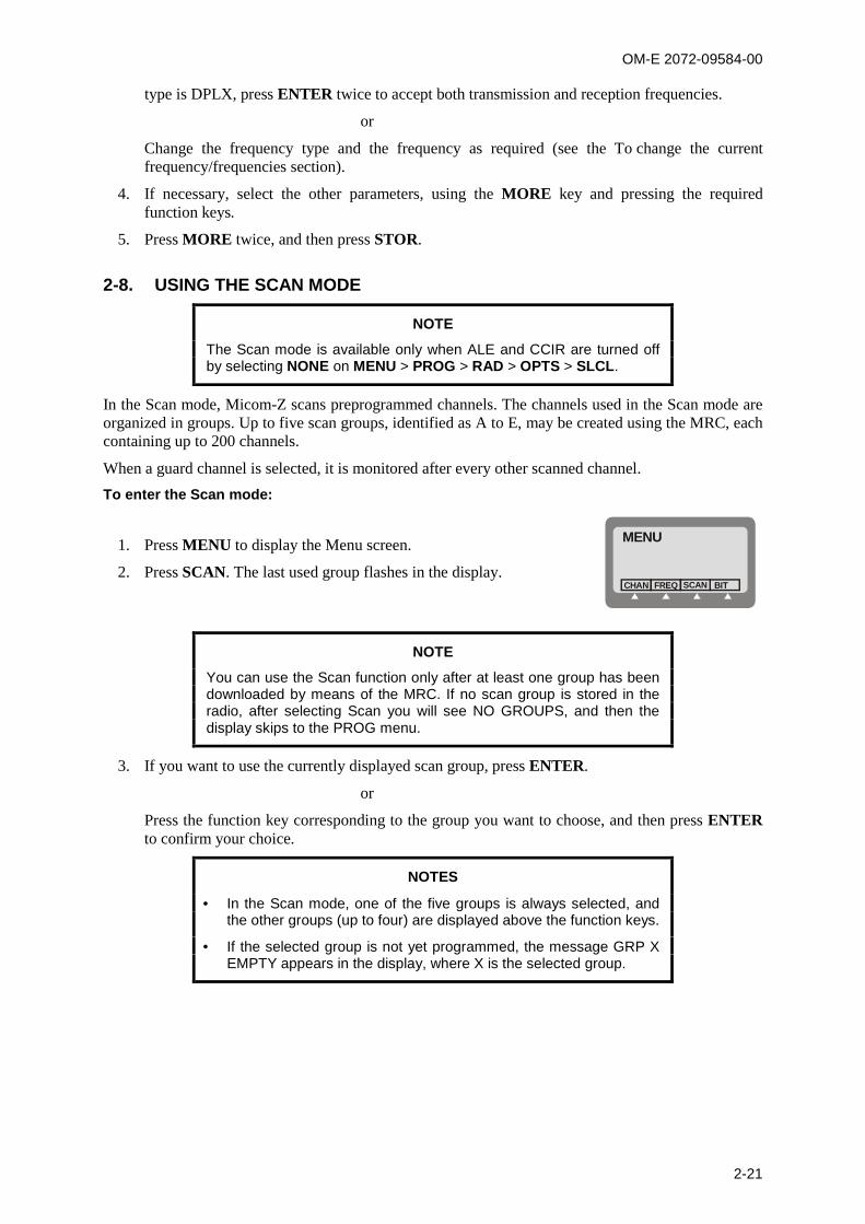
OM-E 2072-09584-00
2-21
type is DPLX, press ENTER twice to accept both transmission and reception frequencies.
or
Change the frequency type and the frequency as required (see the To change the currentfrequency/frequencies section).
4. If necessary, select the other parameters, using the MORE key and pressing the requiredfunction keys.
5. Press MORE twice, and then press STOR.
2-8. USING THE SCAN MODE
NOTE
The Scan mode is available only when ALE and CCIR are turned offby selecting NONE on MENU > PROG > RAD > OPTS > SLCL.
In the Scan mode, Micom-Z scans preprogrammed channels. The channels used in the Scan mode areorganized in groups. Up to five scan groups, identified as A to E, may be created using the MRC, eachcontaining up to 200 channels.
When a guard channel is selected, it is monitored after every other scanned channel.
To enter the Scan mode:
1. Press MENU to display the Menu screen.
2. Press SCAN. The last used group flashes in the display.
MENU
FREQCHAN SCAN BIT
NOTE
You can use the Scan function only after at least one group has beendownloaded by means of the MRC. If no scan group is stored in theradio, after selecting Scan you will see NO GROUPS, and then thedisplay skips to the PROG menu.
3. If you want to use the currently displayed scan group, press ENTER.
or
Press the function key corresponding to the group you want to choose, and then press ENTERto confirm your choice.
NOTES
In the Scan mode, one of the five groups is always selected, andthe other groups (up to four) are displayed above the function keys.
If the selected group is not yet programmed, the message GRP XEMPTY appears in the display, where X is the selected group.

OM-E 2072-09584-00
2-22
2-8.1.1 Scan Mode Options
In the Scan mode you can select various parameters and options, some used to control the scanningand others which can help eliminate noise or otherwise assist reception and/or transmission.
The following options control the scanning operation:
Option Description
STOP Stops the scanning. When scanning is stopped, the label changes to SCAN: pressing F1again starts the scanning.
SLOW Decreases the scanning speed.
FAST Increases the scanning speed.
NOTEThe scan speed can be varied in the range of 150 milliseconds to 5seconds: From 150 to 950 milliseconds, each F2 or F3 pressing results in a
50-millisecond change.
From 1 to 5 seconds, each pressing results in a 1-second change.
GRP Selects a scan group
The other options are identical to those available in the Channel mode (see para. 2-6.2).
NOTE
The changing of the Scan mode options is temporary. When you exitthe Scan mode and then return to Scan, all the current options will belost and replaced by the values configured for the various channels.
OM-E 2072-09584-00
2-23
2-9. USING THE GPS RECEIVER (OPTIONAL)
2-9.1 Overview of GPS Receiver Functions
The GPS receiver is an integral part of the Micom-Z transceiver, and can be used whenever the GPSantenna supplied together with the Micom-Z transceiver is properly connected and installed.
The GPS receiver provides accurate time and navigation data. The navigation data includes thegeographical coordinates (position data) and the altitude. When the Micom-Z transceiver is moving,you can also see the speed and direction (heading).
The format of the navigation data can be selected in accordance with your needs:
LLA format: Latitude, longitude and altitude (LLA). The latitude and longitude are displayed indegrees, with a precision of hundredths of arc minutes (1/100 min); the altitude is reported inmeters, relative to the mean sea level (MSL).
Velocity is reported as the change in the East, North, and Up coordinates, presented in meter/secwith a precision of 0.001 m/sec.
ECEF format: Earth-Centered, Earth-Fixed format for position and velocity. Provides yourposition and velocity in a Cartesian (X, Y, Z) coordinate frame with its center at the Earth'scenter, the Z-axis through the North Pole, and the X-axis through 0 degrees longitude, 0 degreeslatitude. The position is reported in meters.
Velocity for each axis (that is, is the change in the X, Y and Z coordinate) is displayed inmeter/sec, with a precision up to 0.001 m/sec.
The time is always presented on basis of the UTC (Universal Time Coordinated).
The information collected by the GPS receiver can be displayed on the Micom-Z display when usingthe CH and FREQ modes. In the ALE and CCIR modes, the position data can be reported by means ofAMD messages; it can also be automatically reported in response to position queries (also sent byAMD messages).
2-9.2 How to Get the Best Results from your Micom-Z GPS Receiver
The GPS receiver extracts the information it needs by analyzing the signals received from GPSsatellites. These satellite periodically transmit navigation messages, where the transmission of eachcomplete message requires almost 15 minutes. To calculate all the data your GPS receiver is capableof providing, it must receive and decode navigation messages from at least 4 GPS satellites (the GPSreceiver can use as many as 8 satellites to improve accuracy).
Therefore, after turning a GPS receiver on for the first time after a long period of inactivity, it isessential to let the GPS receiver operate continuously for at least 15 minutes, to enable it to collectupdated almanac data. After this initial 15-minute interval, a GPS receiver can relatively rapidlyacquire the satellites and calculate its position; thereafter, a GPS receiver must remain on only for afew minutes in order to be able to provide navigation data.
The internal GPS receiver is always powered when the transceiver is turned on. Therefore, if the GPSantenna is connected, the GPS receiver can start the acquisition process as soon as the transceiver isturned on, and can then track the satellites continuously. Turning the Micom-Z transceiver off willforce the GPS receiver to reacquire the satellites.
2-9.3 Operating the GPS Receiver
2-9.3.1 GPS Menu
The GPS menu is displayed by selecting the GPS item on the FREQ or CH menu. The GPS menustructure is shown in Figure 2-4.

OM-E 2072-09584-00
2-24
CH Mode
FREQ Mode Existing Menuin Figure 2-2
MORE
Existing Menuin Figure 2-3
MORE
MORE MORE
GPSLLA FormatECEF Format
FULLVERTDHORHOR
TIMEDEV
FRMT
XYZ
DXDYDZ
TIMEDEV
FRMT
MORE
MORE
Figure 2-4. GPS Menu
The menu structure depends on the display format, ECEF or LLA, selected by the FMT item. Youcan also press the UP or DOWN panel key to toggle the display format.
a. The items displayed on the GPS menu when using the LLA format are as follows:
FULL Alternating display of the absolute velocity (VEL) in the horizontal plane, andits direction relative to the North (azimuth – AZIMTH).
VERT Alternating display of altitude and up/down velocity.
DHOR Alternating display of North/South and East/West velocities.
HOR Alternating display of latitude and longitude.
TIME Display the time-of-day obtained from the GPS receiver.
DEV Used to check that the GPS receiver is operating.
FMT Toggle the display format (to ECEF).
b. The items displayed on the GPS menu when using the ECEF format are as follows:
X Display the X coordinate.
Y Display the Y coordinate.
Z Display the Z coordinate (altitude).
DX Display the velocity along the X axis.
DY Display the velocity along the Y axis.
DZ Display the velocity along the Z axis.
TIME Display the time-of-day obtained from the GPS receiver.
FULL Alternating display of the absolute velocity (VEL), and its direction relative tothe North (azimuth – AZIMTH).
DEV Used to check that the GPS receiver is operating.
FMT Toggle the display format (to LLA).

OM-E 2072-09584-00
2-25
2-9.3.2 First-Time Operation
The internal GPS receiver is always powered when the transceiver is turned on. Therefore, if the GPSantenna is connected and you are in a good place with a clear view of the sky, the GPS receiver canstart the satellite acquisition process as soon as the transceiver is turned on, and can then track thesatellites continuously.
Thus, the GPS item on the FREQ or CH menu only enables/disables the display of GPS data: theresult is that after selecting GPS, the GPS data can be immediately displayed, and is updated once persecond (time is updated once every 5 seconds).
Before using the GPS receiver, turn the Micom-Z transceiver on and let it operate for at least 15minutes.
2-9.3.3 Operating Instructions
2-9.3.3.1 Switching to the GPS Display
NOTE
You cannot switch to the GPS display if you are using the ALE mode.
1. Select the GPS item by scrolling with the MORE key on the FREQ or CH menu, and thenpressing F2. You will see a message that indicates the current display format, GPS LLA or GPSECEF.
2. If necessary, switch to the alternate display format by pressing the UP or DOWN key.
Alternatively, you can use the GPS menu: press MORE as required to see FMT, and then pressthe key next to FMT (F4).
3. If the GPS receiver operates normally and is ready, you will see the information selected the lasttime the receiver has been used.
2-9.3.3.2 Selecting what to Display
1. Press the key next to the type of information you want to see: use Figure 2-4 to find the key tobe pressed.
2. The displayed information appears on the display and is automatically updated every second.The time is updated every 5 seconds.
3. To change the display of GPS information, scroll to the desired item.
4. To cancel the display of GPS information, select any other menu except GPS.
2-9.3.4 What to do if …
1. If the GPS display mode, GPS LLA or GPS ECEF, does not appear when switching to the GPSdisplay, scroll to the DEV item. You should see the GPS receiver type.
If you see UNKNOWN, turn the Micom-Z transceiver off and after a few minutes turn it backon. If the problem persists, the GPS receiver must be serviced.
If you see NONE, your Micom-Z transceiver does not include the optional GPS receiver.
2. If the requested information does not appear within 15 minutes, but the check in Step 1 above issuccessful, check for proper connection of the GPS antenna cable to the rear GPS antennaconnector of the transceiver.
3. After checking that the antenna is properly connected, check that the GPS antenna did not shiftfrom its intended position, and has a clear view of the sky. Try to improve your location: avoidlocations near trees, high buildings or steep hills.
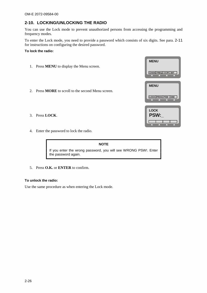
OM-E 2072-09584-00
2-26
2-10. LOCKING/UNLOCKING THE RADIOYou can use the Lock mode to prevent unauthorized persons from accessing the programming andfrequency modes.
To enter the Lock mode, you need to provide a password which consists of six digits. See para. 2-11for instructions on configuring the desired password.
To lock the radio:
1. Press MENU to display the Menu screen.MENU
FREQCHAN CCIR BIT
2. Press MORE to scroll to the second Menu screen.MENU
PROGLOCK PSW DIM
3. Press LOCK.LOCKPSW:_
4. Enter the password to lock the radio.
NOTE
If you enter the wrong password, you will see WRONG PSW!. Enterthe password again.
5. Press O.K. or ENTER to confirm.
To unlock the radio:
Use the same procedure as when entering the Lock mode.
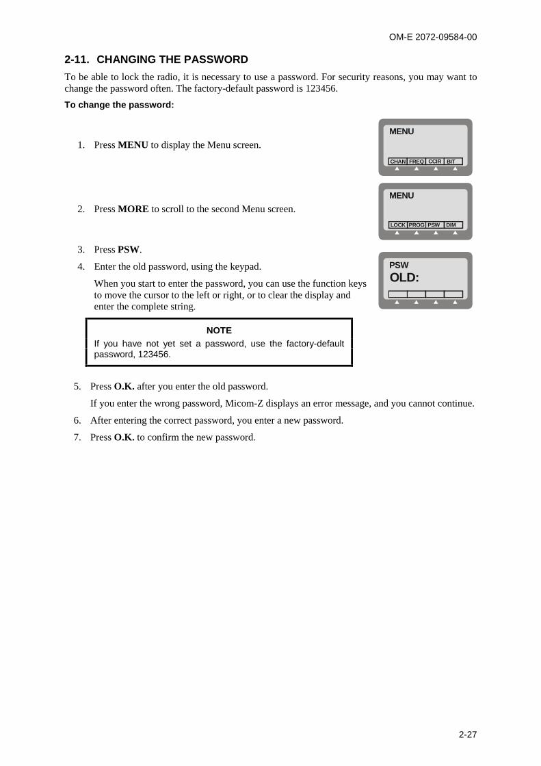
OM-E 2072-09584-00
2-27
2-11. CHANGING THE PASSWORDTo be able to lock the radio, it is necessary to use a password. For security reasons, you may want tochange the password often. The factory-default password is 123456.
To change the password:
1. Press MENU to display the Menu screen.MENU
FREQCHAN CCIR BIT
2. Press MORE to scroll to the second Menu screen.MENU
PROGLOCK PSW DIM
3. Press PSW.
4. Enter the old password, using the keypad.
When you start to enter the password, you can use the function keysto move the cursor to the left or right, or to clear the display andenter the complete string.
PSWOLD:
NOTEIf you have not yet set a password, use the factory-defaultpassword, 123456.
5. Press O.K. after you enter the old password.
If you enter the wrong password, Micom-Z displays an error message, and you cannot continue.
6. After entering the correct password, you enter a new password.
7. Press O.K. to confirm the new password.
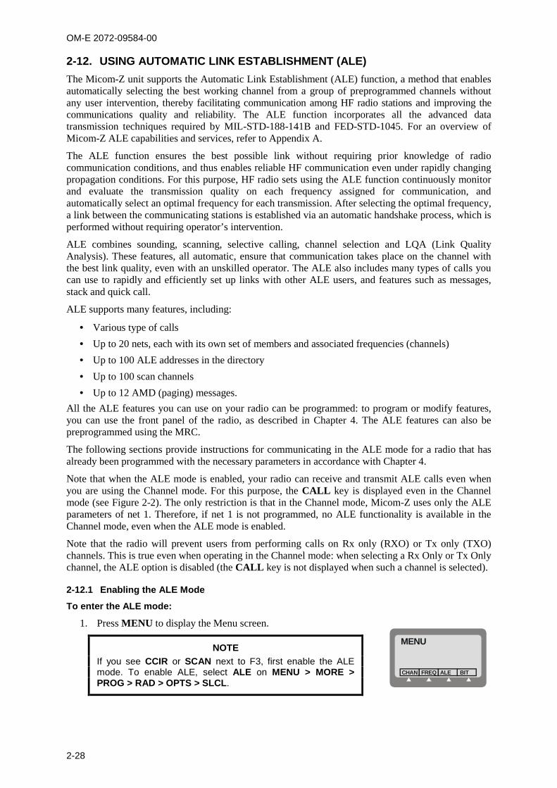
OM-E 2072-09584-00
2-28
2-12. USING AUTOMATIC LINK ESTABLISHMENT (ALE)The Micom-Z unit supports the Automatic Link Establishment (ALE) function, a method that enablesautomatically selecting the best working channel from a group of preprogrammed channels withoutany user intervention, thereby facilitating communication among HF radio stations and improving thecommunications quality and reliability. The ALE function incorporates all the advanced datatransmission techniques required by MIL-STD-188-141B and FED-STD-1045. For an overview ofMicom-Z ALE capabilities and services, refer to Appendix A.
The ALE function ensures the best possible link without requiring prior knowledge of radiocommunication conditions, and thus enables reliable HF communication even under rapidly changingpropagation conditions. For this purpose, HF radio sets using the ALE function continuously monitorand evaluate the transmission quality on each frequency assigned for communication, andautomatically select an optimal frequency for each transmission. After selecting the optimal frequency,a link between the communicating stations is established via an automatic handshake process, which isperformed without requiring operator’s intervention.
ALE combines sounding, scanning, selective calling, channel selection and LQA (Link QualityAnalysis). These features, all automatic, ensure that communication takes place on the channel withthe best link quality, even with an unskilled operator. The ALE also includes many types of calls youcan use to rapidly and efficiently set up links with other ALE users, and features such as messages,stack and quick call.
ALE supports many features, including:
Various type of calls
Up to 20 nets, each with its own set of members and associated frequencies (channels)
Up to 100 ALE addresses in the directory
Up to 100 scan channels
Up to 12 AMD (paging) messages.
All the ALE features you can use on your radio can be programmed: to program or modify features,you can use the front panel of the radio, as described in Chapter 4. The ALE features can also bepreprogrammed using the MRC.
The following sections provide instructions for communicating in the ALE mode for a radio that hasalready been programmed with the necessary parameters in accordance with Chapter 4.
Note that when the ALE mode is enabled, your radio can receive and transmit ALE calls even whenyou are using the Channel mode. For this purpose, the CALL key is displayed even in the Channelmode (see Figure 2-2). The only restriction is that in the Channel mode, Micom-Z uses only the ALEparameters of net 1. Therefore, if net 1 is not programmed, no ALE functionality is available in theChannel mode, even when the ALE mode is enabled.
Note that the radio will prevent users from performing calls on Rx only (RXO) or Tx only (TXO)channels. This is true even when operating in the Channel mode: when selecting a Rx Only or Tx Onlychannel, the ALE option is disabled (the CALL key is not displayed when such a channel is selected).
2-12.1 Enabling the ALE Mode
To enter the ALE mode:
1. Press MENU to display the Menu screen.
NOTEIf you see CCIR or SCAN next to F3, first enable the ALEmode. To enable ALE, select ALE on MENU > MORE >PROG > RAD > OPTS > SLCL.
MENU
FREQCHAN ALE BIT

OM-E 2072-09584-00
2-29
2. Press ALE.
The last active net flashes in the display.
ALENET 7
LQACALL MON
3. To use the displayed net, press ENTER.
To select another net:
Press the UP/DOWN keys until you reach the required number.
or
Type the desired net number or the keypad.
The new net number blinks, indicating that the selection has not yetbeen confirmed.
ALENET 1
LQACALL MON
4. Press ENTER to confirm your choice.
The radio then starts scanning the channels in the selected net (thechanging channel number appears to the right of the net number).
ALENET 1 5
LQACALL MON
2-12.2 ALE Mode Options
Figure 2-5 shows the operator options available in the ALE mode.
ALE
MON
ONOFF
Main Menu
SENDEDITCHAN<- >
ALL
NET
GRP
ANY
WILD
SELF SENDCHAN
SENDPAGECHANSEL
SENDPAGECHANSEL
SENDPAGECHANSEL
SENDPAGECHAN
SENDPAGEGLOBSEL
MULT
MORE
CALL LQA
ONOFF
SENDPAGECHAN
MULT NET SENDPAGECHAN
SENDEDITCHAN<- >
SENDEDITCHAN<- >
SOUNDBDIR
MORE
SENDPAGECHAN
Figure 2-5. ALE Operator Menu
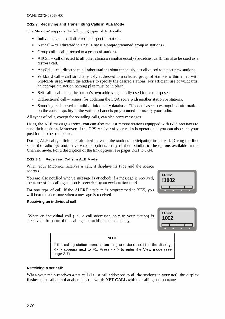
OM-E 2072-09584-00
2-30
2-12.3 Receiving and Transmitting Calls in ALE Mode
The Micom-Z supports the following types of ALE calls:
Individual call – call directed to a specific station.
Net call – call directed to a net (a net is a preprogrammed group of stations).
Group call – call directed to a group of stations.
AllCall – call directed to all other stations simultaneously (broadcast call); can also be used as adistress call.
AnyCall – call directed to all other stations simultaneously, usually used to detect new stations.
Wildcard call – call simultaneously addressed to a selected group of stations within a net, withwildcards used within the address to specify the desired stations. For efficient use of wildcards,an appropriate station naming plan must be in place.
Self call – call using the station’s own address, generally used for test purposes.
Bidirectional call – request for updating the LQA score with another station or stations.
Sounding call – used to build a link quality database. This database stores ongoing informationon the current quality of the various channels programmed for use by your radio.
All types of calls, except for sounding calls, can also carry messages.
Using the ALE message service, you can also request remote stations equipped with GPS receivers tosend their position. Moreover, if the GPS receiver of your radio is operational, you can also send yourposition to other radio sets.
During ALE calls, a link is established between the stations participating in the call. During the linkstate, the radio operators have various options, many of them similar to the options available in theChannel mode. For a description of the link options, see pages 2-31 to 2-34.
2-12.3.1 Receiving Calls in ALE Mode
When your Micom-Z receives a call, it displays its type and the sourceaddress.
You are also notified when a message is attached: if a message is received,the name of the calling station is preceded by an exclamation mark.
For any type of call, if the ALERT attribute is programmed to YES, youwill hear the alert tone when a message is received.
FROM!1002
Receiving an individual call:
When an individual call (i.e., a call addressed only to your station) isreceived, the name of the calling station blinks in the display.
FROM1002
NOTE
If the calling station name is too long and does not fit in the display, appears next to F1. Press to enter the View mode (seepage 2-7).
Receiving a net call:
When your radio receives a net call (i.e., a call addressed to all the stations in your net), the displayflashes a net call alert that alternates the words NET CALL with the calling station name.

OM-E 2072-09584-00
2-31
Receiving an AllCall:
NOTE
You can program your radio to ignore incoming AllCalls. If the radio isset to ignore incoming AllCalls, it stops scanning when an AllCall isreceived but it does not display, nor lets you hear the call. At the endof the AllCall, the radio automatically returns to the scanning mode.
When an AllCall is received, the display flashes an AllCall alert that alternates ALLCALL with thecalling station name.
Receiving an AnyCall:
NOTE
You can program your radio to ignore incoming AnyCalls. If the radiois set to ignore incoming AnyCalls, it stops scanning when an AnyCallis received but it does not display, nor lets you hear the call. At theend of the AnyCall, the radio automatically returns to the scanningmode.
When an AnyCall is received, the display flashes an AllCall alert that alternates ANYCALL with thecalling station name.
Receiving a sounding call:
When the radio is in the ALE mode and it receives a sounding call from another station, the callingstation name appears in the display, preceded by the letter S to identify that the call is a sounding call.
Within a few seconds, the radio automatically returns to the mode used before the call was received.
Receiving a bidirectional handshake call:
When the radio receives a bidirectional handshake call from another station, your radio respondsautomatically, without your intervention. Within a few seconds, the radio automatically returns to themode used before the call was received.
If the bidirectional handshake includes a message, the calling station name and the received messageare stored in the stack, and the STAK function key appears.
To answer an incoming call:
Press any key (including PTT, but not ESC) to accept the call. The calling station name stops blinking,and is displayed steadily. The alert tone is no longer heard. The radio is now in the link state with thecalling station.
NOTE
When an AllCall is received, no link is actually established but you canhear the calling station.
If the received call includes a message, an exclamation mark precedes the station name, and the nameis followed by a colon and the message.
If the calling station name and message are too long and do not fit in the display, press to enterthe View mode, where you can scroll right and left to display the whole message.
To display LQA for the received call:
Press LQA. You will see the channel in use, and its LQA score.
2-12.3.2 The Link State
After the radio successfully receives or transmits a call, it is in the link state.

OM-E 2072-09584-00
2-32
If the call was received from another radio, the display includes the word FROM in the first line, aswell as the name of the station which initiated the call (if a message has been received, it is alsodisplayed).
If the call was initiated by your radio, the display includes the word LINK in the first line, as well asthe destination address.
While in the link state, you can operate the following functions using the function keys.
NOTE
The change of link options is temporary. When you exit the link state,all the changed parameters will be lost.
Option Description
Activates the View mode, where you can view the entire station address.
Page Enables you to select a message to be sent to the station you are linked to. After amessage is selected, you can edit it. The PAGE function is not available when receivingan AllCall.
LQA Displays the channel on which the link was established, and the LQA score of the currentlink. If the name of the station you are linked to is not in your directory, this function will notbe available.
The LQA key is displayed only if you established the link in the ALE mode (in the Channelmode, this function is not available, because the call is received/transmitted on the currentchannel).
MON Turns on and off monitoring by means of the speaker.
RPL Replaces the currently-used channel with a channel with a better LQA score.
The radio disconnects the link, replaces the channel being used, and initiates the call onceagain. The RPL function is available only for individual calls, and only for the call initiator.The RPL key is displayed only if you established the link in the ALE mode (in the Channelmode this function is not available, because the call is received/transmitted on the currentchannel).
BAND Toggles between upper sideband (USB) and lower sideband (LSB). The sideband changetakes places only after the current call is ended.
SQ Toggles the squelch on/off. Always select OFF for CW operation.
DSP Accesses the Digital Signal Processing menu, which includes the following options:
CLAR Enables to control the clarifier (off/lower frequency/higher frequency). Thefunction key is not available for TXO (transmit only) channels.
NF Enables to control the notch filter (off/lower frequency/higher frequency).The function key is not available for TXO (transmit only) channels.
CLIP Toggles the clipper on/off.
CC Toggles the ClearCom function on/off.
ATTN Toggles the attenuator on/off.
PWR Selects the transmit power level: LOW – 25W; MED – 60W; HIGH – 100W; MAX – 125W.
MODE Selects the operation mode: SSB – single sideband AME – amplitude modulation equivalent PLT – single sideband with pilot signal).
AGC Controls the automatic gain control function (fast/slow/off).
OM-E 2072-09584-00
2-33
Option Description
BW Selects the filter bandwidth. HS – high sensitivity filter (450 to 1500 Hz) for best voice communication under
marginal conditions 2.7 – 300 to 2700 Hz 3.0 – 300 to 3000 Hz 3.3 – 300 to 3300 Hz. Always select this bandwidths for data transmission LSM – bandwidth optimized for use with low speed modems (1450 to 1950 Hz) CW (Continuous Wave or Morse operation). The bandwidth used in this case is
selected by MENU > PROG > RAD > PRMT > CW.
RCLV Displays the receive level. The RCLV item appears only if the received signal level displayis not permanently enabled using MENU > PROG > RAD > PRMT > RCLV.
FREQ Displays the current frequency.
2-12.3.2.1 Replacing the Current Channel While in the Link State
If during an individual call you find that the channel in use is not good enough, you can replace it witha better channel.
NOTES
Channel replacement is possible only during an individual call inthe ALE mode.
Only the initiator of a call can replace the channel in use.
To replace the channel:
1. Press MORE to scroll to the second link state menu.
2. Press RPL to replace the channel in use.
3. The radio disconnects the link, replaces the channel being used, and initiates the call once again.
NOTE
Even if a message was transmitted when the original link wasinitiated, the new link will be initiated without the message.
2-12.3.2.2 Using the Caller Stack
The caller stack stores information about unanswered calls. The stack entry contains the self-addressof the calling station, and any message sent by the calling station when it sent the call set up request.The stack can contain up to 10 calls.
When the stack is not empty, you can see the stack icon in the display.
The radio records an address in the stack only once, even if the same caller made several unansweredcalls. However, if the same caller sent calls with different messages, all such calls will be saved in thestack. If you see STAK in the options area, the stack includes at least one call you never viewedbefore. The stack is arranged in FIFO order, that is, the first address that enters the stack is also thefirst that you see on the display.
To view the calls in the stack:
1. Press STAK. The radio displays information on the total number of calls in the stack, andinformation on the first call. If the number of characters exceeds the available space, press to activate the view mode.
2. Use the UP/DOWN keys to view any additional calls in the stack.
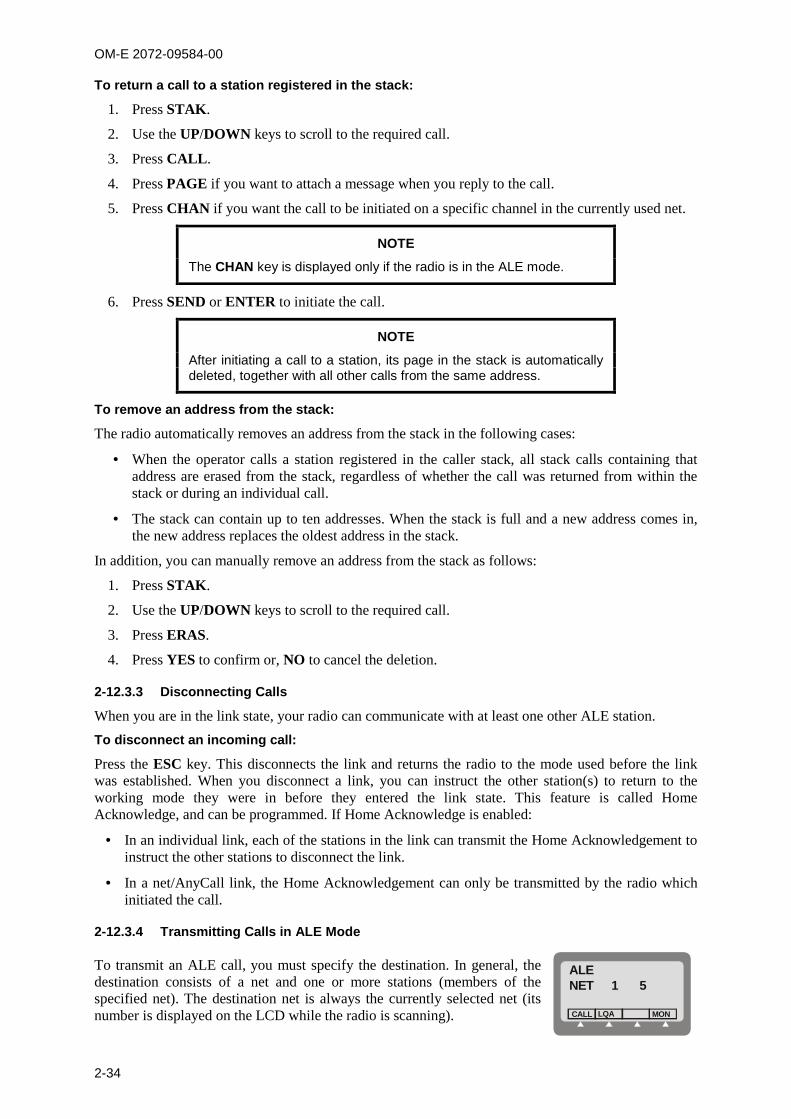
OM-E 2072-09584-00
2-34
To return a call to a station registered in the stack:
1. Press STAK.
2. Use the UP/DOWN keys to scroll to the required call.
3. Press CALL.
4. Press PAGE if you want to attach a message when you reply to the call.
5. Press CHAN if you want the call to be initiated on a specific channel in the currently used net.
NOTE
The CHAN key is displayed only if the radio is in the ALE mode.
6. Press SEND or ENTER to initiate the call.
NOTE
After initiating a call to a station, its page in the stack is automaticallydeleted, together with all other calls from the same address.
To remove an address from the stack:
The radio automatically removes an address from the stack in the following cases:
When the operator calls a station registered in the caller stack, all stack calls containing thataddress are erased from the stack, regardless of whether the call was returned from within thestack or during an individual call.
The stack can contain up to ten addresses. When the stack is full and a new address comes in,the new address replaces the oldest address in the stack.
In addition, you can manually remove an address from the stack as follows:
1. Press STAK.
2. Use the UP/DOWN keys to scroll to the required call.
3. Press ERAS.
4. Press YES to confirm or, NO to cancel the deletion.
2-12.3.3 Disconnecting Calls
When you are in the link state, your radio can communicate with at least one other ALE station.
To disconnect an incoming call:
Press the ESC key. This disconnects the link and returns the radio to the mode used before the linkwas established. When you disconnect a link, you can instruct the other station(s) to return to theworking mode they were in before they entered the link state. This feature is called HomeAcknowledge, and can be programmed. If Home Acknowledge is enabled:
In an individual link, each of the stations in the link can transmit the Home Acknowledgement toinstruct the other stations to disconnect the link.
In a net/AnyCall link, the Home Acknowledgement can only be transmitted by the radio whichinitiated the call.
2-12.3.4 Transmitting Calls in ALE Mode
To transmit an ALE call, you must specify the destination. In general, thedestination consists of a net and one or more stations (members of thespecified net). The destination net is always the currently selected net (itsnumber is displayed on the LCD while the radio is scanning).
ALENET 1 5
LQACALL MON
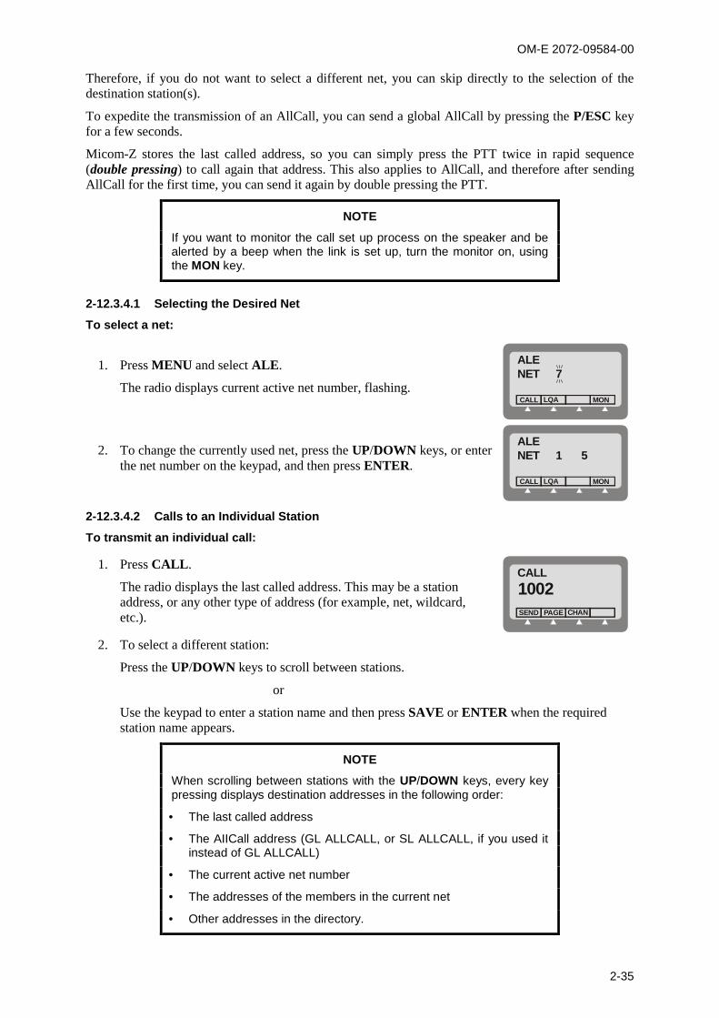
OM-E 2072-09584-00
2-35
Therefore, if you do not want to select a different net, you can skip directly to the selection of thedestination station(s).
To expedite the transmission of an AllCall, you can send a global AllCall by pressing the P/ESC keyfor a few seconds.
Micom-Z stores the last called address, so you can simply press the PTT twice in rapid sequence(double pressing) to call again that address. This also applies to AllCall, and therefore after sendingAllCall for the first time, you can send it again by double pressing the PTT.
NOTE
If you want to monitor the call set up process on the speaker and bealerted by a beep when the link is set up, turn the monitor on, usingthe MON key.
2-12.3.4.1 Selecting the Desired Net
To select a net:
1. Press MENU and select ALE.
The radio displays current active net number, flashing.
ALENET 7
LQACALL MON
2. To change the currently used net, press the UP/DOWN keys, or enterthe net number on the keypad, and then press ENTER.
ALENET 1 5
LQACALL MON
2-12.3.4.2 Calls to an Individual Station
To transmit an individual call:
1. Press CALL.
The radio displays the last called address. This may be a stationaddress, or any other type of address (for example, net, wildcard,etc.).
CALL1002
PAGESEND CHAN
2. To select a different station:
Press the UP/DOWN keys to scroll between stations.
or
Use the keypad to enter a station name and then press SAVE or ENTER when the requiredstation name appears.
NOTE
When scrolling between stations with the UP/DOWN keys, every keypressing displays destination addresses in the following order:
The last called address
The AIICall address (GL ALLCALL, or SL ALLCALL, if you used itinstead of GL ALLCALL)
The current active net number
The addresses of the members in the current net
Other addresses in the directory.

OM-E 2072-09584-00
2-36
3. Press SEND or ENTER to initiate the call.
4. The radio now starts the link set up process. During this process, you will see TO alternatingwith the number of the channel on which the set up request is being sent (the channel maychange, if the called station does not answer on the first channel(s)).
NOTE
While the radio is initializing the link, you can press STOP or ESC toabort the entire process.
5. After the link is established, you will see a LINK message. Now you may press the PTT andstart talking.
NOTE
If the link with the selected station cannot be set up, you will see for afew seconds a flashing NO LINK message.
6. To disconnect the link, press the ESC key (see page 2-31).
NOTE
If you want to call again the same station, double-press the PTT touse the quick-call feature (see page 2-37).
To transmit on a specific channel:
1. Initiate a call as explained above (page 2-33 or 2-35) and select the desired station.
2. Press CHAN to select a specific channel.
The channel with the best LQA score is displayed. The speaker is unmuted to enable you tocheck the channel quality by listening to it.
NOTE
If the name of the called station has been edited and the new stationname is not in the directory, no LQA score is displayed.
3. Press BEST to select the channel with the best LQA score...
NOTE
If the name of the called station has been edited and the new stationname is not in the directory, the channel displayed after pressingBEST is the first scanned channel of the net.
… or
Press the UP/DOWN keys to scroll to the channel of your choice.
NOTE
You can use this option to transmit a call to a station operating in theChannel mode. If the other station is in the Channel mode, your radioswitches to the Channel mode for the duration of the call, and thenreturns to the ALE mode after the link to that station is disconnected.
4. Press SEND or ENTER to initiate the call.
5. The radio now starts the link set up process. During this process, you will see TO alternatingwith the number of the channel on which the set up request is being sent (the channel maychange, if the called station does not answer on the first channel(s)).
OM-E 2072-09584-00
2-37
NOTE
While the radio is initializing the link, you can press STOP or ESC toabort the entire process.
6. After the link is established, you will see a LINK message. Now you may press the PTT andstart talking.
7. To disconnect the link, press the ESC key (see page 2-31).
2-12.3.4.3 Quick Call
A quick call is a call to the last station you tried to call (regardless of whether the call was successfulor not). In the ALE mode, the channel used for the original call is reused for the quick call.
The Quick Call feature can be enabled or disabled as part of ALE parameters programming.
NOTES
Quick Call will not transmit a message, even if the last callcontained a message.
The first time the station is switched to the ALE or Channel mode,quick call is not possible as no "most recent" station data exists.
To send a quick call:
Double-press the PTT of your microphone or handset. The radio automatically tries to contact the lastcalled station.
During this process, you will see TO alternating with the number of the channel on which the set uprequest is being sent (the channel may change, if the called station does not answer on the firstchannel(s)).
NOTE
While the radio is initializing the link, you can press STOP or ESC toabort the entire process.
2-12.3.4.4 Using Autodial
The Autodial feature lets you use a single digit to call a preprogrammed address. There are tenprogrammable Autodial addresses, where each can include a message.
To use Autodial to send a call:
1. Press # on the keypad.
NOTE
If you do not select an auto-address within a few seconds, the displayautomatically reverts to the previous state.
2. Press the desired preprogrammed Autodial number (0 to 9).
The programmed address is immediately displayed; if a message is preprogrammed, anexclamation sign will appear before the station name.
Press PAGE if you want to attach a message to the call or to replace/edit a preprogrammedattached message. See page 2-38.
OM-E 2072-09584-00
2-38
NOTE
If the Autodial number you enter is not programmed, the messageNOT PROG will be displayed.
3. Press CHAN if you want the call to be initiated on a specific channel. See page 2-38.
4. Press ENTER or SEND to start the call.
5. The radio now starts the link set up process. During this process, you will see TO alternatingwith the number of the channel on which the set up request is being sent (the channel maychange, if the called station does not answer on the first channel(s)).
NOTE
While the radio is initializing the link, you can press STOP or ESC toabort the entire process.
6. After the link is established, you will see a LINK message. Now you may press the PTT andstart talking.
7. To disconnect the link, press the ESC key (see page 2-31).
2-12.3.4.5 Sending Messages
You can send messages (page) together with the initial call (before the link is set up), and alsowhenever necessary while the link is already set up (that is, when your station is in a link with thedestination station). In the link state, if you are making an individual call, both the receiving and thecalling station can send messages to the other station. This is also true for net calls and group calls.
To transmit an individual call with a message:
1. Initiate a call as explained above (page 2-33 or 2-35) and select the desired station.
2. Press PAGE to add a message. The last sent message is displayed.
Press the UP/DOWN keys to scroll to the required message.
or
To edit the message, press EDIT and use the keypad to enter a new message.
3. Press SAVE when the message is ready.
4. Press SEND or ENTER to initiate the call.
5. Proceed with the call as explained above (page 2-33 or 2-35).
To send a message during a call (link state):
1. Press PAGE.
NOTE
If this function key is not displayed, you cannot send a message in thepresent mode.
2. Select or edit the desired message as explained on page 2-37.
3. Press SEND or ENTER to send the message.
4. The radio now starts the link set up process for this message (this process is similar to theprocess used to set up the link for this call). During this process, you will see TO alternatingwith the number of the channel being used.
OM-E 2072-09584-00
2-39
NOTES
While the radio is initializing the link, you can press STOP or ESCto abort the entire process.
If the link needed to send the message to the selected stationcannot be set up, you will see for a few seconds a flashing NOLINK message.
2-12.3.4.6 Other Types of Calls
In addition to calls to individual stations described on the pages 2-34 to 2-38, additional types of callscan be used to help you call multiple stations (see list on page 2-30).
NOTE
A properly designed address assignment plan is needed to takeadvantage of the special ALE calling modes.
The special call types are reached under a special submenu, designated MULT (see Figure 2-5 for itsorganization).
To select a special call type:
1. Press CALL.
The radio displays the last called address. This may be a station address, or any other type ofaddress (for example, AllCall, net, wildcard, etc.).
2. Press MORE once.
3. Press MULT to display the first page of special calls. If the desired call type is located on thispage, press the corresponding function key to select it.
4. If necessary, press MORE again to display the next page.
NOTE
Pressing MORE again return you to the first page of special calls: donot use the ESC key, as it cancels the MULT option.
5. Go to the page listed below for detailed instructions.
Option Capabilities See Page …ALL AllCall – call directed to all the other stations simultaneously; usually used as
a distress call.2-40
NET Net call – call directed to a net (a net is a preprogrammed group of stations).Up to 20 nets can be defined.
2-41
GRP Group call – call directed to a group of individually selected stations. Groupscan be preprogrammed, but you can also select the stations to be called andsave the selection for reuse. Up to five groups can be defined.
2-42
ANY AnyCall – call directed to all the other stations simultaneously, usually used todetect new stations.
2-44
WILD Wildcard call – call simultaneously addressed to a selected group of stationswithin a net, with wildcards used within the address to specify the desiredstations. Wildcard calls use the special ALE addressing modes. If you are notfamiliar with these modes, you should review Appendix A.
2-45
OM-E 2072-09584-00
2-40
SELF Self call – call using the station’s own address, generally used for testpurposes.
2-46
2-12.3.4.7 Transmitting AIICalls
An AllCall is a message which your radio uses to establish a connection with all the other stationssimultaneously, and is typically used to broadcast a message or send a distress call. An AllCall canalso include a message.
In addition to this type of AllCall (referred to as a global (GL) AllCall), it is also possible to useselective (SL) AllCall: this is a simultaneous call addressed only to all the stations whose names(addresses) end with a character you specify.
NOTE
If so required, you can set your radio so that it cannot send AIICalls.
You cannot select the channel on which an outgoing AllCall will be sent: outgoing AllCalls are senton the AllCall channel defined for the currently selected net, or on the best scanned channel of the net.
There are two ways to send a global AllCall: using the ESC key or using the CALL function. Aselective AllCall can be sent only using the CALL function.
To send global AllCall using the ESC key:
1. Press ESC continuously for a few seconds. The radio starts sending the GL AllCall.
During this process, you will see TO alternating with the number of the channel on which theset up request is being sent.
NOTE
While the radio is initializing the link, you can press STOP or ESC toabort the entire process.
2. After a delay, you will see LINK with a flashing GL ALLCALL.
3. Confirm the link set up by pressing ENTER or the PTT. The GL ALLCALL message stopsflashing, and you can start talking.
4. Press PAGE if you want to send a message. See page 2-38 for details.
5. To end the call, press ESC.
To send global AllCall using the CALL function:
1. Press CALL. The radio displays the last called address.
2. Press the UP/DOWN keys until you reach GL ALLCALL.
3. Press PAGE if you want to add a message to the call. See page 2-38 for details.
4. Press SEND or ENTER to start the call.
The call now proceeds as for call initiated by pressing the ESC key.
To send selective AllCall:
1. Press CALL. The radio displays the last called address.
2. Press MORE once.
3. Press MULT to display the first page of special calls.
4. Press ALL.
5. Press SEL.

OM-E 2072-09584-00
2-41
NOTE
If you decide to send a Global AllCall, press GLOB.
6. Type the desired character (only one character is accepted).
NOTE
You can press ? if you decide to send a global AllCall.
7. Confirm your selection by pressing ENTER.
NOTE
If you decide to send a global AllCall, press GLOB.
8. Press SEND or ENTER to start the call. The radio starts sending the selective AllCall.
NOTE
While the radio is initializing the link, you can press STOP or ESC toabort the entire process.
9. After a delay, you will see LINK, and you can start talking.
10. Press PAGE if you want to send a message. See page 2-38 for details.
11. To end the call, press ESC.
Transmitting Net Calls
Before starting, select the net you want to use as explained on page 2-35.
NOTES
You can program nets using the front panel, or the MRC.
The radio must be programmed as a MASTER radio in the net (anALE Programming option) in order to be able to transmit net calls.
To transmit a net call:
1. Press CALL.
The radio displays the last called address.
If you see the net you want, skip directly to Step 5 below, otherwise continue as explainedbelow.
2. Select the NET option as explained on page 2-39.
3. Press PAGE if you want to attach a message to the call.
4. Press CHAN if you want to initiate the call on a specific channel.
5. Press SEND or ENTER to initiate the call.
The radio now starts the link set up process. During this process, you will see TO alternatingwith the number of the channel on which the set up request is being sent.
NOTE
While the radio is initializing the link, you can press STOP or ESC toabort the entire process.
OM-E 2072-09584-00
2-42
When a net call is transmitted, each member in the net responds to the call and the initiator ofthe call receives an indication of the response on the display.
6. After links have been established, you can start talking.
7. To end the call, press ESC.
2-12.3.4.8 Transmitting Group Calls
Group calls let you call several individual stations in your net (at least 2) at once. Thus, you can use agroup call to communicate with a few select stations, while other stations can still communicate atwill, using other channels available to your net.
You can call up to 5 stations in a group call. The only restriction is that the total length of all theaddresses cannot exceed 12 ALE words (36 characters). If the maximum allowed length is exceeded,you get a BUFF FULL error.
NOTES
If you need to check beforehand the length, remember that eachALE word must include 3 characters. Therefore, when an addressis not an exact multiple of 3, stuffing symbols are automaticallyadded in the last positions.
ALE addresses are categorized in accordance with their leadingALE word (that is, their first three characters: if the address is shortand has only one or two characters, stuffing symbols @ areadded). When assembling a group you must also take intoconsideration that the maximum number of different addresscategories (as identified by their leading word) in one group is 5. Ifmore are included, then when you try to send the call you will seeUFA WRONG. In this case, remove addresses to make the groupmore homogenous.
To make a group call, first you must specify the stations to be included in the group. The addresses ofthe stations you include in the group can be saved as a group; the radio can store up to 4 differentgroups. If a group including the desired stations is already programmed, you can directly initiate thecall to the desired group.
NOTE
Before starting, you may want to select a different net to use: seeinstructions on page 2-35.
To transmit a group call:
1. Press CALL.
The radio displays the last called address.
If you see the group you want, skip directly to Step 6 below, otherwise continue as explainedbelow.
2. Select the GRP option as explained on page 2-39.
3. The first group displayed is always group 1. If this is the group you want, skip directly to Step 6below, otherwise press the UP or DOWN arrows until you see the desired group.
4. Press PAGE if you want to attach a message to the group call.
5. Press CHAN if you want to initiate the call on a specific channel.
6. Press SEND or ENTER to initiate the call.

OM-E 2072-09584-00
2-43
NOTES
If the selected group does not include at least 2 stations, yourrequest is rejected and you will see for a few seconds AT LEAST 2.
If the addresses in the group have more than 5 different leadingwords, your request is rejected and you will see for a few secondsUFA WRONG.
The radio now starts the link set up process. During this process, you will see TO alternatingwith the number of the channel on which the set up request is being sent.
NOTE
While the radio is initializing the link, you can press STOP or ESC toabort the entire process.
When a net call is transmitted, each member in the group responds to the call and the initiator ofthe call receives an indication of the response on the display.
7. After links have been established, you can start talking.
8. To end the call, press ESC.
To define or change a group:
1. Press CALL and select the GRP option, as you do to start a group call (page 2-42).
2. The first group displayed is always group 1. If this is the group you want, skip directly to Step 3below, otherwise press the UP or DOWN arrows until you see the desired group.
3. To select the stations you want in this group, press SEL.
NOTE
The following example explains how to build a new group, but you canuse the same procedures to change an existing group.
4. After pressing SEL, you will see the DIR screen. Therefore, you can select stations from theaddresses already stored in the directory, or type new addresses using the keypad.
To select an address from these already in the directory:
1. Use the UP and DOWN arrows to display the desired directory entry, and then press ADD.
The label above the selected entry changes to ADDED, to indicate that it is now included in thegroup.
Now you can also have the option (ERAS ) to delete the entry from the group.
NOTE
If adding the station would cause the total length of the stationaddresses in the group to exceed 12 ALE words, then after pressingADD you will see BUFF FULL and the process stops.
2. Repeat the procedure described above until the group includes only the desired stations.
As you scroll through the directory, you will see DIR for stations that can be added, andADDED for those already added. If the station you want to add to the group is not in thedirectory:
Enter the new station using the keypad. If you make a mistake, scroll to the desired positionusing and/or , or clear (CLR ) the whole entry and start again.
3. When ready, press SAVE to store the new station in the directory.
OM-E 2072-09584-00
2-44
Now you can add it to the group by pressing ADD.
2-12.3.4.9 Transmitting AnyCalls
An AnyCall is a general broadcast which your radio uses to simultaneously establish links with otherstations. An AnyCall can also include a message.
NOTE
If so required, you can set your radio so that it cannot send AnyCalls.
AnyCall is somewhat similar to AllCall, except that it requests responses from the other stations andtherefore it can be used to detect new stations. Another difference is that you can also select thechannel on which the AnyCall will be transmitted (alternatively, you can let the radio selectautomatically the channel).
You can send three types of AnyCalls (see also description of addressing modes on Appendix A):
General: the address sent by your radio is @@?. This is a simultaneous call addressed to all thestations.
Selective: you specify the last character of the address. This is a simultaneous call addressedonly to the stations whose names (addresses) end with a character you specify.
Double selective: similar to selective, except that you specify the last two characters of theaddress.
To make an AnyCall, first you must select the address to be used for the call.
Micom-Z will wait for responses for a certain time before entering the link state with all the stationsthat responded within this interval (the maximum number of stations that are accepted in an AnyCall is16).
NOTE
Before starting, you may want to select a different net to use: seeinstructions on page 2-35.
To transmit an AnyCall:
1. Press CALL. The radio displays the last called address.
If you see the address you want (that is, you want to repeat the last AnyCall), skip directly toStep 10 below, otherwise continue as explained below.
2. Press MORE once.
3. Press MULT to display the first page of special calls.
4. Press ANY.
5. Press SEL.
NOTE
If you try to send (SEND) the call without first selecting an address,your attempt is rejected and you see for a few seconds NOT PROG.
6. Select the AnyCall address:
To send a general AnyCall, press ?.
To send a selective AnyCall, enter the desired character (any character except #, @ or ?).
To send a double-selective AnyCall, enter two characters.
7. Confirm your selection by pressing ENTER.
OM-E 2072-09584-00
2-45
8. Press PAGE if you want to attach a message to the call.
9. Press CHAN if you want to initiate the call on a specific channel.
10. Press SEND or ENTER to initiate the call.
The radio now starts the AnyCall process. During this process, you will see TO alternating withthe number of the channel on which the request is being sent.
NOTE
You can press STOP or ESC to abort the entire process.
When an AnyCall is transmitted, the initiator of the call receives an indication of each stationanswering the call (its address flashes in the display, until replaced by the next answeringstation).
11. After a programmed interval (or after 16 stations answer, whichever comes first), the link isestablished. Now you can start talking.
12. To end the call, press ESC.
2-12.3.4.10 Transmitting Wildcard Calls
Wildcard calls, that is, calls in which the destination address includes the wildcard character ?, let youto simultaneously address multiple stations with a single address:
Any station receiving an address with wildcards stops scanning and checks the address length: ifthe number of characters in the received address is different from the number of characters in itsown self-address, the station ignores the call.
If the received address matches the length, a receiving station checks the significant positions inthe received address against its own. For example, the stations JOHN and JOIN will both accepta call with the address JO?N.
Each station accepting the call answers the calling station in a pseudo-random slot.
Micom-Z will wait for responses for a certain time before entering the link state with all the stationsthat responded within this interval (the maximum number of stations that are accepted in a wildcardcall is 16). Therefore, with the wildcard option, the link set up process takes more time, because theradio waits longer to get responses (it cannot “guess” the number of stations that will answer).
Before continuing, you may wish to review Appendix A, which presents details on ALE addressing(including the use of wildcards in addresses).
NOTE
Before starting, you may want to select a different net to use: seeinstructions on page 2-35.
To transmit a wildcard call:
1. Press CALL. The radio displays the last called address.
If you see the address you want (that is, you want to repeat the last wildcard call), skip directlyto Step 11 below, otherwise continue as explained below.
2. Press MORE once.
3. Press MULT to display the first page of special calls.
4. Press MORE again to display the next page.
5. Press WILD to start.
6. Press SEL.

OM-E 2072-09584-00
2-46
NOTE
If you try to send (SEND ) the call without first selecting an address,your attempt is rejected and you see for a few seconds NOT PROG.
7. Select the desired address:
To insert a wildcard, press ?
Enter the desired characters using the keypad.
8. Confirm your selection by pressing ENTER.
9. Press PAGE if you want to attach a message to the call.
10. Press CHAN if you want to initiate the call on a specific channel.
11. Press SEND or ENTER to initiate the call.
NOTE
If the selected group does not include at least 2 stations, your requestis rejected and you will see for a few seconds AT LEAST 2.
The radio now starts the process. During this process, you will see TO alternating with thenumber of the channel on which the request is being sent.
NOTE
You can press STOP or ESC to abort the entire process.
12. After a delay, you will see LINK with the wildcard address flashing.
13. Confirm the link set up by pressing ENTER or the PTT. The address stops flashing, and youcan start talking.
14. To end the call, press ESC.
2-12.3.4.11 Transmitting a Self Call
The self-call is a test call addressed to your own address within the currently selected net. Its purposeis to check that your radio set is OK and can transmit calls (to check reception, you can simply listento other radio sets).
When you send the self-call, the radio starts sending calls to its own address, successively, on eachchannel in the current net. After going through all the channels, the call process stops. No otherresponse is expected.
NOTE
You can also include the self address in a group call.
To send a self-call:
1. Press CALL. The radio displays the last called address.
2. Press MORE once.
3. Press MULT to display the first page of special calls.
4. Press MORE again to display the next page.
5. Press SELF to start the self-call.
6. You may select now a specific channel to perform the call, by pressing CHAN. See details onpage 2-36.

OM-E 2072-09584-00
2-47
7. When ready, press SEND to start transmitting. The display alternates between your self-addressand the channel used for the call is sent. If you did not select a specific channel, the channelnumber changes as the radio sends the call on each channel assigned to the selected net.
After all the channels have been used, the call automatically stops.
You can press STOP at any time to end the call sooner.
2-12.3.4.12 Bidirectional Handshake
The bidirectional handshake is used to exchange LQA scores with other stations without establishing alink.
NOTE
The Micom-Z can also be programmed to automatically initiate the callto the station after finishing the bidirectional handshake (using theBDLK parameter reached under the ALE programming options).
A bidirectional handshake can be carried out with a single station or with all stations in the net. It canbe carried out either on a single channel, or on all the net channels. When required, a message can alsobe added to the procedure.
After a bidirectional handshake with a single station, the LQA matrices of both radios are updated.The operator can then initiate a call to that station and obtain the best channel automatically.
When the bidirectional handshake procedure is performed with a net, all the stations in the net updatetheir LQA tables.
Micom-Z will wait for responses for a certain time before entering the link state with all the stationsthat responded within this interval (the maximum number of stations that are accepted in abidirectional handshake is 16).
NOTE
Before starting, you may want to select a different net to use: seeinstructions on page 2-35.
To execute a bidirectional handshake with an individual station:
1. Press LQA to enter the LQA menu.
2. Press BIDR. The last called address is displayed. If this is the address you want, skip directly toStep 6 below.
3. To select a different address, use the UP/DOWN keys to scroll to the required address in thedirectory, and then press ENTER to confirm your selection.
or
If the station you want to add to the group is not in the directory:
Enter the new station using the keypad. If you make a mistake, scroll to the desired positionusing and/or , or clear (CLR) the whole entry and start again.
When ready, press SAVE to store the new station in the directory.
4. Press PAGE if you wish to attach a message to the bidirectional handshake process. Afterconfirming the message, exclamation mark precedes the name of the called station, indicatingthat a message has been attached.
5. Press CHAN if you wish to execute a bidirectional handshake process on a specific channel.
6. Press SEND or ENTER in order to initiate the bidirectional handshake process. During thisprocess, you will see TO alternating with the number of the channel on which the set up requestis being sent.
OM-E 2072-09584-00
2-48
NOTE
During the bidirectional handshake process, you can press STOP orESC to abort the entire process.
To execute a bidirectional handshake with a net:
1. Press LQA to enter the LQA menu.
2. Press BIDR.
The last called address is displayed. If this is the net you want, skip directly to Step 8 below.
3. Press MORE.
4. Press MULT.
5. Press NET.
NOTE
You cannot change the net number at this stage – the bidirectionalhandshake is always performed on the currently selected net. Tochange the net, see page 2-35.
6. Press PAGE if you want to attach a message to the handshake.
7. Press CHAN if you want to initiate the handshake on a specific channel.
8. Press SEND or ENTER to initiate the handshake. During this process, you will see TOalternating with the number of the channel on which the handshake is being sent.
NOTE
While the radio is initializing the handshake, you can press STOP orESC to abort the entire process.
2-12.3.4.13 Sounding
Sounding is used to test the quality of the channels and propagation paths of all channels in the net.
The sounding signal is normally repeated automatically, at regular intervals. A complete round ofsounding messages, or "sounding cycle" can be programmed to 30, 60, 90, or 120 minutes, or can beset to OFF.
Sounding can also be initiated manually whenever necessary, even if automatic sounding is enabled.
To manually initiate sounding:
1. Press LQA to enter the LQA menu.
2. Press SOND.
3. Press ON to start manual sounding, or OFF to stop an ongoing sounding process.
NOTES
The radio automatically returns to ALE mode when sounding isstopped.
When the radio transmits a sounding signal, the Tx bar is visible.
2-12.3.5 Using the Inlink Function
When the inlink function is enabled, the stations participating in a call are automatically notified by aDISC message whenever another participant leaves (disconnects from) the call.
OM-E 2072-09584-00
2-49
The link is then automatically disconnected when only one station is left (that is, after all the otherparticipants disconnected).
The inlink function is available in any type of call that involves the setting up of a link usingbidirectional handshaking. Therefore, you can use it in individual calls, group calls, net calls, etc., butnot in AllCalls and self calls.
NOTE
For the inlink function to operate correctly, it must be enabled on allthe stations.
Do not enable the inlink function when communicating with a radiothat does not support the full ALE capabilities in accordance withMIL-STD-188-141B.
To avoid disconnecting the link too soon as a result of inactivity (that is, after the programmed PTTtime-out interval (PTOT)), each participant can request other stations to wait beyond the PTOTinterval (up to 10 minutes more) before automatic disconnection occurs.
This option (TOT – time-out interval) is displayed over the F4 key after the link is set up: to send arequest for the other stations to wait more time, press the TOT key.
2-12.3.6 Transmitting ALE Calls in the Channel Mode
The ALE option is available in both the ALE and Channel modes and therefore, the radio can alsoanswer ALE calls.
The transmission process is similar for both operating modes, with the following differences:
In the Channel mode, every call is initiated on the currently selected channel.
The LQA function is not available in the Channel mode: sounding and bidirectional calls canonly be initiated in the ALE mode.
When the radio is in the Channel mode, it uses the parameters programmed for net 1.
NOTE
If net 1 is not programmed, there is no ALE functionality in theChannel mode, even if the ALE option is turned on.
2-12.4 Using ALE Mode to Send and Request GPS Position Data
You can use the ALE AMD service to:
1. Send your position to any another destination (including one-to-many).
2. Request the position of another Micom-Z transceiver equipped with a GPS receiver. You canmake this type of request only when you call an individual station.
Note that the operations described above automatically set up a link between the two stations andtherefore it is necessary to disconnect the link when it is no longer needed. For this purpose, it isrecommended to enable Home Acknowledge, and/or enable the PTT time-out function.

OM-E 2072-09584-00
2-50
NOTE
AMD messages with the GPS position do not enter the stack (theinformation such message carries is good only at the time you got it):if you do not read the message in time, you can no longer retrieve themessage at a later time.
Thus, you must allow sufficient time for the destination station to readthe position message before when link is disconnected. This isparticularly important when Home Acknowledge is enabled: themessage will disappear as soon as you disconnect the link.
2-12.4.1 Request GPS Position
To automatically get the position of another Micom station, use the following procedure:
1. Select the CALL mode (either from the ALE mode or the CHAN mode).
2. Select the destination address (you can make only an individual call).
3. Select the PAGE selection mode.
4. Scroll until you see the RMT POS message, and then send the message.
5. Your station starts the link set up to the selected station; after the link is set up, you will see theresponse AMD of the called station, which includes its latitude and longitude. POSITIONINVALID means that the remote station cannot provide its location.
6. You may now continue with voice communication, or disconnect the link to the called station.
NOTE
Radio sets of various vendors can also accept GPS position requests.The position request is made by sending the string FIXPOSIT as anAMD message.
2-12.4.2 Sending Own GPS Position
You can use the PAGE service to send the AMD message that appears in position 14 in the default listof AMD messages to transmit your own position to a remote station.
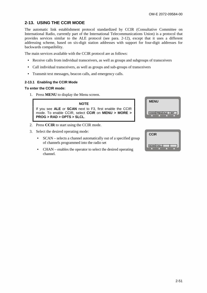
OM-E 2072-09584-00
2-51
2-13. USING THE CCIR MODEThe automatic link establishment protocol standardized by CCIR (Consultative Committee onInternational Radio, currently part of the International Telecommunications Union) is a protocol thatprovides services similar to the ALE protocol (see para. 2-12), except that it uses a differentaddressing scheme, based on six-digit station addresses with support for four-digit addresses forbackwards compatibility.
The main services available with the CCIR protocol are as follows:
Receive calls from individual transceivers, as well as groups and subgroups of transceivers
Call individual transceivers, as well as groups and sub-groups of transceivers
Transmit text messages, beacon calls, and emergency calls.
2-13.1 Enabling the CCIR Mode
To enter the CCIR mode:
1. Press MENU to display the Menu screen.
NOTEIf you see ALE or SCAN next to F3, first enable the CCIRmode. To enable CCIR, select CCIR on MENU > MORE >PROG > RAD > OPTS > SLCL.
MENU
FREQCHAN ALE BIT
2. Press CCIR to start using the CCIR mode.
3. Select the desired operating mode:
SCAN – selects a channel automatically out of a specified groupof channels programmed into the radio set
CHAN – enables the operator to select the desired operatingchannel.
CCIR
CALLSCAN

OM-E 2072-09584-00
2-52
2-13.2 CCIR Mode Options
Figure 2-6 shows the operator options available in the CCIR mode.
CHAN BCN EMRGPAGE
SENDEDIT
GPSR GPSD TEL
SEND
EGPS HUPSEND
CCIR
MORE
Main Menu
MORE
SCAN
ABCDE
CALL
AMD 1
SENDEDIT
AMD 2
SENDEDIT
AMD
Figure 2-6. CCIR Operator Menu
Option Description
SEND Send a call
CHAN Used to select a specific operating channel
PAGE Enables you to select a message to be sent to the station you are linked to. After amessage is selected, you can edit it
BCN Send a beacon call
EMRG Send an emergency call
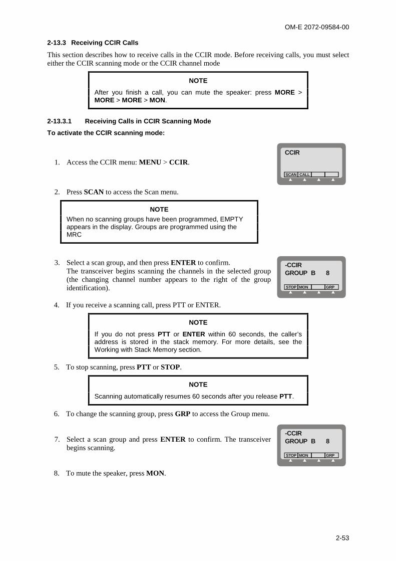
OM-E 2072-09584-00
2-53
2-13.3 Receiving CCIR Calls
This section describes how to receive calls in the CCIR mode. Before receiving calls, you must selecteither the CCIR scanning mode or the CCIR channel mode
NOTE
After you finish a call, you can mute the speaker: press MORE >MORE > MORE > MON.
2-13.3.1 Receiving Calls in CCIR Scanning Mode
To activate the CCIR scanning mode:
1. Access the CCIR menu: MENU > CCIR.CCIR
CALLSCAN
2. Press SCAN to access the Scan menu.
NOTEWhen no scanning groups have been programmed, EMPTYappears in the display. Groups are programmed using theMRC
3. Select a scan group, and then press ENTER to confirm.The transceiver begins scanning the channels in the selected group(the changing channel number appears to the right of the groupidentification).
-CCIRGROUP B 8
MONSTOP GRP
4. If you receive a scanning call, press PTT or ENTER.
NOTE
If you do not press PTT or ENTER within 60 seconds, the caller’saddress is stored in the stack memory. For more details, see theWorking with Stack Memory section.
5. To stop scanning, press PTT or STOP.
NOTE
Scanning automatically resumes 60 seconds after you release PTT.
6. To change the scanning group, press GRP to access the Group menu.
7. Select a scan group and press ENTER to confirm. The transceiverbegins scanning.
-CCIRGROUP B 8
MONSTOP GRP
8. To mute the speaker, press MON.

OM-E 2072-09584-00
2-54
2-13.3.2 Receiving Calls in the CCIR Channel Mode
This section describes how to receive calls in the CCIR Channel mode.
2-13.3.2.1 Receiving Individual, Sub-Group, Group, and All Calls
When your transceiver receives a call, the caller’s address appears in the display.To receive individual, sub-group, group, and all calls:
1. Press any button (including PTT) to accept the call.CH 12F 15,000.00
BAND SQ DSP
2. If you do not press any buttons (including PTT) for 60 seconds, the call automatically ends.
3. After the call ends, press MORE > MORE > MORE > MON to mute the speaker.
2-13.3.2.2 Receiving AMD Messages
When your transceiver receives an AMD message, the caller’s address and message appear in thedisplay.
To receive AMD messages:
1. Press to view the message.
2. Press any button (including PTT) to end the call.
2-13.3.2.3 Receiving Emergency Calls
When your transceiver receives an emergency call, the caller’s address appears in the display.
To receive emergency calls:
1. Press any button (including PTT) to accept the call.CH 12F 15,000.00
BAND SQ DSP
NOTE
If you do not press any buttons (including PTT) for 60 seconds, thecaller’s address is stored in the stack memory. For more details, seethe Working with Stack Memory section.
2. After the call ends, press MORE > MORE > MORE > MON to mute the speaker.
2-13.4 Transmitting CCIR Calls
This section describes how to transmit calls.
NOTE
Before you transmit calls, you must configure at least one directory.For more details, see the Configuring CCIR Directory Entries sectionin Chapter 4.
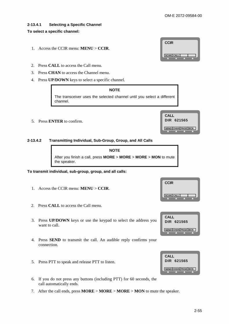
OM-E 2072-09584-00
2-55
2-13.4.1 Selecting a Specific Channel
To select a specific channel:
1. Access the CCIR menu: MENU > CCIR.CCIR
CALLSCAN
2. Press CALL to access the Call menu.
3. Press CHAN to access the Channel menu.
4. Press UP/DOWN keys to select a specific channel.
NOTE
The transceiver uses the selected channel until you select a differentchannel.
5. Press ENTER to confirm.CALLDIR 621565
CHANSEND BCNPAGE
2-13.4.2 Transmitting Individual, Sub-Group, Group, and All Calls
NOTE
After you finish a call, press MORE > MORE > MORE > MON to mutethe speaker.
To transmit individual, sub-group, group, and all calls:
1. Access the CCIR menu: MENU > CCIR.CCIR
CALLSCAN
2. Press CALL to access the Call menu.
3. Press UP/DOWN keys or use the keypad to select the address youwant to call.
CALLDIR 621565
CHANSEND BCNPAGE
4. Press SEND to transmit the call. An audible reply confirms yourconnection.
5. Press PTT to speak and release PTT to listen.CALLDIR 621565
CHANSEND BCNPAGE
6. If you do not press any buttons (including PTT) for 60 seconds, thecall automatically ends.
7. After the call ends, press MORE > MORE > MORE > MON to mute the speaker.

OM-E 2072-09584-00
2-56
2-13.4.3 Transmitting Calls in Scanning Mode
While the radio is in the scanning mode, you can send an individual call by entering the destinationaddress, and selecting the desired channel.
To transmit an individual call during scanning:
1. While the radio is scanning ...
-CCIRGRP A 4
MONSTOP GRP
... type the destination address. If you make a mistake, use thebackspace arrow to clear it, or clear the entire address by pressingCLR.
-CCIR236985
SAVE CLR
2. After checking the address, press ENTER. You will be prompted toselect the channel to be used.
Press UP/DOWN keys to select a specific channel, and then pressENTER to confirm.
CALLCH 8
3. Press SEND to transmit the call. An audible reply confirms yourconnection.
CALL236985
CHANSEND BCNPAGE
4. After the call ends, press MORE > MORE > MORE > MON to mute the speaker.
2-13.4.4 Editing and Transmitting AMD Messages
NOTE
You can transmit AMD messages only as individual calls. For moredetails, see the Configuring AMD Messages in CCIR Mode section inChapter 4.
To edit and transmit AMD messages:
1. Access the CCIR menu: MENU > CCIR.
2. Press CALL to access the Call menu.
3. Press UP/DOWN keys or use the keypad to select the individual address you want to call.
4. Press PAGE to access the Page menu.
5. Press UP/DOWN keys to select the message you want to transmit. You have 3 selections:
AMD 1 – AMD message 1
AMD 2 – AMD message 2
AMD (without a number) – free text message.
6. If necessary, you can change (edit) the selected message. Press EDIT and then use the keypadto edit your message: when ready, press SAVE.
7. Press SEND to transmit the message.

OM-E 2072-09584-00
2-57
2-13.4.5 Transmitting Beacon Calls
To transmit beacon calls:
1. Access the CCIR menu: MENU > CCIR.CCIR
CALLSCAN
2. Press CALL to access the Call menu.
3. Press UP/DOWN keys or use the keypad to select the address of theremote radio you want to call.
CALLDIR 621565
CHANSEND BCNPAGE
4. Press BCN to transmit the beacon call.
5. After receiving the beacon call, the remote radio returns four tones, which are reproduced byyour transceiver. Listen carefully to the four tones, to judge the quality of the connection (noisyor clear). If your receive level monitor is enabled, also pay attention to the received signalstrength while the tones are heard.
2-13.4.6 Transmitting Emergency Calls
To transmit an emergency call:
1. Access the CCIR menu: MENU > CCIR.CCIR
CALLSCAN
2. Press CALL to access the Call menu.
3. Press UP/DOWN keys or use the keypad to select the address youwant to call.
CALLDIR 621565
CHANSEND BCNPAGE
4. Press MORE to scroll to the next menu screen.
5. Press EMRG to transmit the emergency call. An audible reply confirms your connection.
6. Press PTT to speak and release PTT to listen.
7. If you do not press any buttons (including PTT) for 60 seconds, the call automatically ends.
8. After the call ends, press MORE > MORE > MORE > MON to mute the speaker.
2-13.5 Working with Stack Memory
If you receive a call, but do not answer within 60 seconds, the caller’s address is stored in the stackmemory. Note the following:
You can only access stack memory if there is at least one stack memory entry. In other words, ifyou did not miss at least one call, you need not (and cannot) access the stack memory.
Only the caller’s address is stored in the stack memory, but not any message attached to the call.
The stack memory can contain up to 10 entries and works on a first-in, first-out (FIFO) basis.
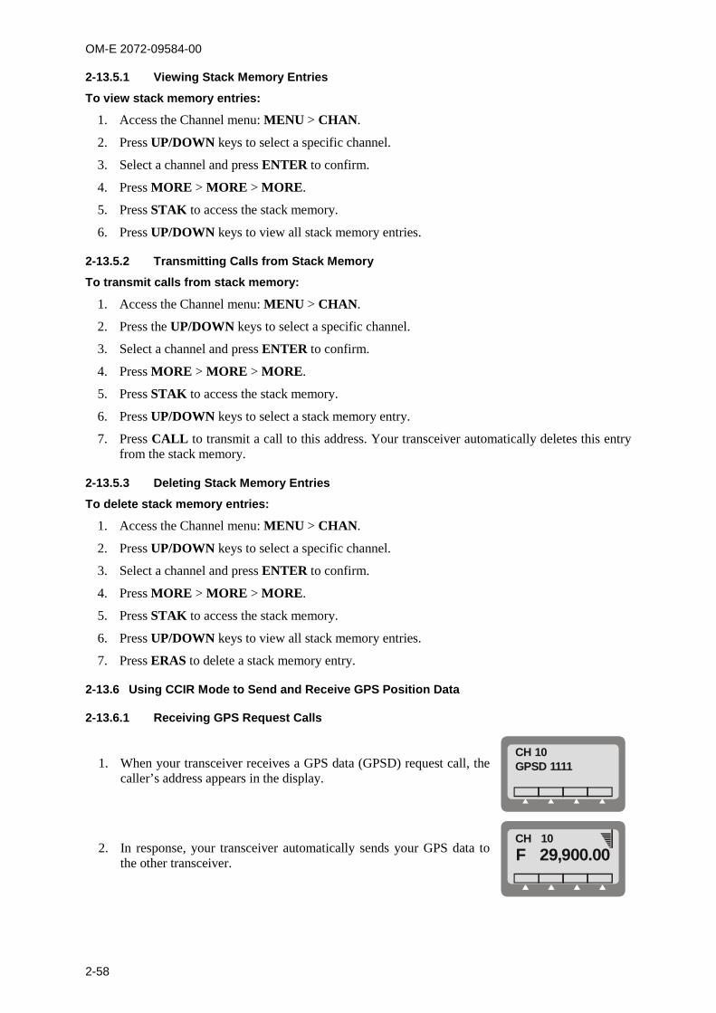
OM-E 2072-09584-00
2-58
2-13.5.1 Viewing Stack Memory Entries
To view stack memory entries:
1. Access the Channel menu: MENU > CHAN.
2. Press UP/DOWN keys to select a specific channel.
3. Select a channel and press ENTER to confirm.
4. Press MORE > MORE > MORE.
5. Press STAK to access the stack memory.
6. Press UP/DOWN keys to view all stack memory entries.
2-13.5.2 Transmitting Calls from Stack Memory
To transmit calls from stack memory:
1. Access the Channel menu: MENU > CHAN.
2. Press the UP/DOWN keys to select a specific channel.
3. Select a channel and press ENTER to confirm.
4. Press MORE > MORE > MORE.
5. Press STAK to access the stack memory.
6. Press UP/DOWN keys to select a stack memory entry.
7. Press CALL to transmit a call to this address. Your transceiver automatically deletes this entryfrom the stack memory.
2-13.5.3 Deleting Stack Memory Entries
To delete stack memory entries:
1. Access the Channel menu: MENU > CHAN.
2. Press UP/DOWN keys to select a specific channel.
3. Select a channel and press ENTER to confirm.
4. Press MORE > MORE > MORE.
5. Press STAK to access the stack memory.
6. Press UP/DOWN keys to view all stack memory entries.
7. Press ERAS to delete a stack memory entry.
2-13.6 Using CCIR Mode to Send and Receive GPS Position Data
2-13.6.1 Receiving GPS Request Calls
1. When your transceiver receives a GPS data (GPSD) request call, thecaller’s address appears in the display.
CH 10GPSD 1111
2. In response, your transceiver automatically sends your GPS data tothe other transceiver.
CH 10F 29,900.00

OM-E 2072-09584-00
2-59
2-13.6.2 Receiving GPS Data from Other Stations
When your transceiver receives a GPS data call, the caller’s address andGPS data appear in the display.
-CCIR!1133:PV LT
To receive GPS data calls:
1. Press ↔ to view the caller’s GPS data.
POSITION INVALID means that the remote station cannot provideits location.
PV indicates that the following data is valid.
-CCIR!1111:PV
NOTE
The caller’s GPS data disappears and your transceiver returns to itsprevious mode if you do not select ↔ within 60 seconds, or press anybutton other than ↔.
In both cases, the caller’s address is stored in your stack memory, butfrom the stack memory you cannot view the caller’s GPS data.
2. Press → to see the entire message.
CH 10LT 03877.33
HOME END
3. Press any button (including PTT) to end the call. The caller’s GPSdata disappears.
CH 10F 29,900.00CALL MON
2-13.6.3 Transmitting Emergency GPS Calls
To transmit an emergency GPS (EGPS) call:
1. Access the CCIR menu.
2. Select CALL to access the Call menu.
CALLLAST 1234
CHANSEND BCNPAGE
3. Press UP/DOWN keys, or use the keypad to select the address youwant to call.
CALLDIR 1119
CHANSEND BCNPAGE
4. Press MORE twice to scroll to the correct menu screen.
CALLDIR 1119
HUPEGPS
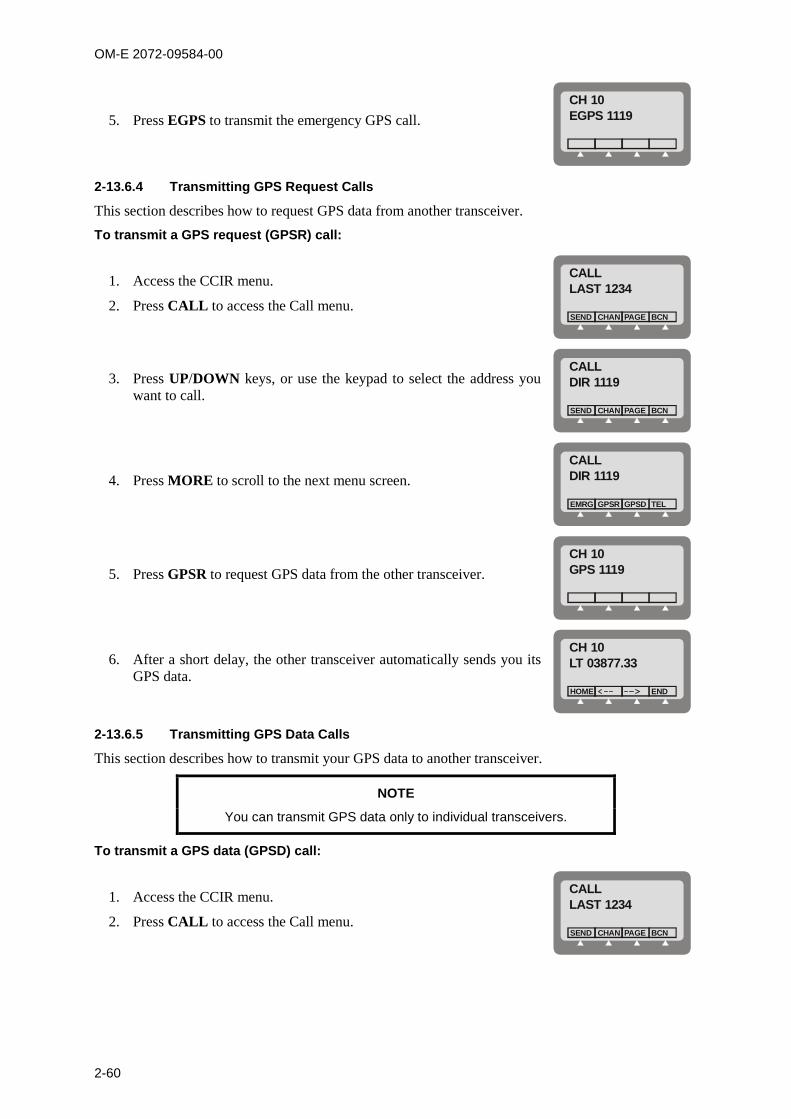
OM-E 2072-09584-00
2-60
5. Press EGPS to transmit the emergency GPS call.
CH 10EGPS 1119
2-13.6.4 Transmitting GPS Request Calls
This section describes how to request GPS data from another transceiver.
To transmit a GPS request (GPSR) call:
1. Access the CCIR menu.
2. Press CALL to access the Call menu.
CALLLAST 1234
CHANSEND BCNPAGE
3. Press UP/DOWN keys, or use the keypad to select the address youwant to call.
CALLDIR 1119
CHANSEND BCNPAGE
4. Press MORE to scroll to the next menu screen.
CALLDIR 1119
GPSREMRG TELGPSD
5. Press GPSR to request GPS data from the other transceiver.
CH 10GPS 1119
6. After a short delay, the other transceiver automatically sends you itsGPS data.
CH 10LT 03877.33
HOME END
2-13.6.5 Transmitting GPS Data Calls
This section describes how to transmit your GPS data to another transceiver.
NOTE
You can transmit GPS data only to individual transceivers.
To transmit a GPS data (GPSD) call:
1. Access the CCIR menu.
2. Press CALL to access the Call menu.
CALLLAST 1234
CHANSEND BCNPAGE

OM-E 2072-09584-00
2-61
3. Press UP/DOWN keys, or use the keypad to select the address youwant to call.
CALLDIR 1119
CHANSEND BCNPAGE
4. Press MORE to scroll to the next menu screen.
CALLDIR 1119
GPSREMRG TELGPSD
5. Press GPSD to transmit your GPS data to the other transceiver.
CH 10GPSD 1119

OM-E 2072-09584-00
2-62
Intentionally Left Blank
OM-E 2072-09584-00
3-1
CHAPTER 3
INSTALLATION
3-1. SCOPE
This Chapter provides installation instructions for Micom-Z.
The information presented in this Chapter includes:
Unpacking – para. 3-2.
Installation planning guidelines – para. 3-3.
Installation procedures for Micom-Z – para. 3-4, 3-5 and 3-6.
Post-installation checks – para. 3-7.
Do not touch the antenna and the RF connectors when the Micom-Z is turned on.
Make sure that the antenna is not located near high-voltage lines.
During transmission, high RF voltages appear at the RF connectors, the antenna cables, and on the antenna itself. These voltages may cause severe injury or death on contact.
Antenna can assume hazardous voltage ijn transmission mode. Antenna accessible parts shall be suitably guarded / insulated from touch! Antenna connection (shield) shall be permanently connected to protective earth in building installation by a service person in accordance with the national code and regulations
Operating and maintenance personnel must be familiar with the applicable safety requirements and regulations before attempting to install or operate Micom-Z radio sets. Severe injury or death could result from failure to comply with the safety practices.
3-2. UNPACKING
a. A preliminary inspection of the equipment containers should be made prior to unpacking.
Evidence of damage should be noted and reported immediately to the proper authorities.
Unpack the equipment as follows:
(1) Place each container on a clean flat surface, cut all straps, and open or remove the top.
(2) Take out each item carefully and place it securely on a clean surface.
(3) Remove the packing material while looking for small items.
(4) Fold and store the containers and packing materials in accordance with standard
procedures.
b. Checking Unpacked Equipment.
(1) Inspect all items for damage. Immediately report any damage found.
(2) Check all items against the items listed in the accompanying packing slip and/or the
appropriate list of items given in the equipment manuals.
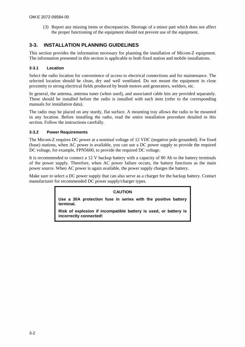
OM-E 2072-09584-00
3-2
(3) Report any missing items or discrepancies. Shortage of a minor part which does not affect
the proper functioning of the equipment should not prevent use of the equipment.
3-3. INSTALLATION PLANNING GUIDELINES
This section provides the information necessary for planning the installation of Micom-Z equipment.
The information presented in this section is applicable to both fixed station and mobile installations.
3-3.1 Location
Select the radio location for convenience of access to electrical connections and for maintenance. The
selected location should be clean, dry and well ventilated. Do not mount the equipment in close
proximity to strong electrical fields produced by brush motors and generators, welders, etc.
In general, the antenna, antenna tuner (when used), and associated cable kits are provided separately.
These should be installed before the radio is installed with each item (refer to the corresponding
manuals for installation data).
The radio may be placed on any sturdy, flat surface. A mounting tray allows the radio to be mounted
in any location. Before installing the radio, read the entire installation procedure detailed in this
section. Follow the instructions carefully.
3-3.2 Power Requirements
The Micom-Z requires DC power at a nominal voltage of 12 VDC (negative pole grounded). For fixed
(base) stations, when AC power is available, you can use a DC power supply to provide the required
DC voltage, for example, FPN5600, to provide the required DC voltage.
It is recommended to connect a 12 V backup battery with a capacity of 80 Ah to the battery terminals
of the power supply. Therefore, when AC power failure occurs, the battery functions as the main
power source. When AC power is again available, the power supply charges the battery.
Make sure to select a DC power supply that can also serve as a charger for the backup battery. Contact
manufacturer for recommended DC power supply/charger types.
CAUTION
Use a 30A protection fuse in series with the positive battery terminal.
Risk of explosion if incompatible battery is used, or battery is incorrectly connected!

OM-E 2072-09584-00
3-3
+
+
__
Connect hereAC power cable
Connect toprotective ground using
wide copper strap
12V Battery
Fuse30A
Black
RedToRadio
RADIOTerminals
BATTERYTerminals
Fuse30A
Figure 3-1. FPN5600 Power Supply Connections
3-3.3 Grounding
The resistance measured between the Micom-Z body and the system ground should be as small as
feasible. Failure to provide proper grounding will degrade system operation and cause RF voltage to
be present on the equipment chassis.
Wide copper straps, as short as possible, should be used for grounding. These straps should be
clamped or bonded to the vehicle body.
For vehicular installations, the vehicle body must be properly grounded during fixed station use. This
can be achieved by means of ground rods. Where the soil is dry and sandy, ground radials should be
used.
CAUTION
The earthing stud shall be permanently connected to protective earth in building installation by authorized personnel. Protecvtive grounding shall be the first to connected and the last to be disconnected.
3-3.4 Vehicular Noise Reduction
Most vehicles contain several noise sources which can greatly disturb radio reception (for example,
the high voltage ignition sparks that are produced at the vehicle's plugs, and the alternator activity). If
necessary, install a noise reduction kit.
3-3.5 Antenna and Antenna Tuner Unit (ATU)
For fixed stations, dipole and broadband antennas, which provide a nominal impedance of 50 , can
be used. In such applications, the antenna can be directly connected to the Micom-Z ANT connector.
For other applications, and in particular when using whip antennas, long wire antennas, and any
antenna which does not present a 50 impedance over the full operating frequency range, an antenna
tuner unit (ATU) is necessary. Suitable ATUs, for example, F2265 and FLN2818, are available from
the manufacturer; these ATUs can be used in both mobile and base station applications. An externally
mounted mobile automatic antenna system, FAD1410, is also available.
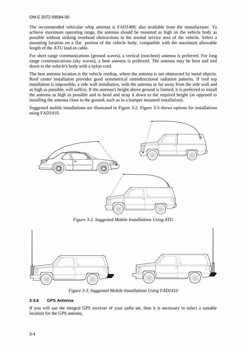
OM-E 2072-09584-00
3-4
The recommended vehicular whip antenna is FAD1400, also available from the manufacturer. To
achieve maximum operating range, the antenna should be mounted as high on the vehicle body as
possible without striking overhead obstructions in the normal service area of the vehicle. Select a
mounting location on a flat portion of the vehicle body, compatible with the maximum allowable
length of the ATU lead-in cable.
For short range communications (ground waves), a vertical (non-bent) antenna is preferred. For long
range communications (sky waves), a bent antenna is preferred. The antenna may be bent and tied
down to the vehicle's body with a nylon cord.
The best antenna location is the vehicle rooftop, where the antenna is not obstructed by metal objects.
Roof center installation provides good symmetrical omnidirectional radiation patterns. If roof top
installation is impossible, a side wall installation, with the antenna as far away from the side wall and
as high as possible, will suffice. If the antenna's height above ground is limited, it is preferred to install
the antenna as high as possible and to bend and strap it down to the required height (as opposed to
installing the antenna close to the ground, such as in a bumper mounted installation).
Suggested mobile installations are illustrated in Figure 3-2. Figure 3-3 shows options for installations
using FAD1410.
Figure 3-2. Suggested Mobile Installations Using ATU
Figure 3-3. Suggested Mobile Installations Using FAD1410
3-3.6 GPS Antenna
If you will use the integral GPS receiver of your radio set, then it is necessary to select a suitable
location for the GPS antenna.

OM-E 2072-09584-00
3-5
3-3.6.1 GPS Antenna Description
The GPS antenna is a compact active omnidirectional antenna with magnetic
mounting, which attaches easily and firmly to vehicle’s steel body parts, even
when painted. The antenna will not attach to non-magnetic alloys (e.g., aluminum
alloys), nor to parts made of composite materials (e.g., fiberglass).
The antenna connects to the GPS connector of the Micom-Z transceiver through a 5-meter (15 feet)
long coaxial cable, which is part of the antenna. This cable carries both DC power for the antenna, and
the received GPS signals.
The antenna is 42 mm wide by 50.5 mm long by 13.8 mm high (1.65”1.99”0.55”), and it requires a
minimal ground plane of 60 by 60 mm (2.36”2.36”) to provide the specified performance.

OM-E 2072-09584-00
3-6
3-3.6.2 Selecting a Proper Location for the GPS Antenna
GPS satellites transmit their special signals in the 1575 MHz range: such signals do not penetrate
conductive surfaces. When selecting the location of the GPS antenna, you should also be aware that
strong local interference as well as reflections from nearby objects may disrupt normal reception and
degrade the signal quality.
Thus, the GPS antenna should be installed on horizontal surfaces, in a place that provides a clear view
of the sky, which, in as far as possible, is not obstructed by large objects. For example, the roof of the
passenger’s cabin is a good place for the GPS antenna.
Moreover, you should not park the vehicle under dense foliage or other cover, for example, in a
garage, if you want to get a position fix from your GPS receiver.
NOTE
When the GPS antenna is installed on a metal surface for prolonged periods, care must be taken to insulate the antenna, to prevent galvanic corrosion.
After installing the antenna, route its cable to the GPS connector on the rear of the Micom-Z, and
make sure to avoid running it parallel to the other transceiver cables.
3-3.7 Cooling
Micom-Z units are cooled by free air convection. Therefore, make sure that sufficient free space is
available around the equipment to enable free air flow.
When it is necessary to use Micom-Z in applications that require continuous transmission for
prolonged intervals, it is recommended to install Micom-Z on the optional cooling tray.
3-3.8 Installation Data
All the dimensions are in mm.
3-3.8.1 Dash-Mount Micom-Z Model
Figure 3-4 shows the dimensions of the dash-mount Micom-Z transceiver model.
Figure 3-4. Dash-Mount Micom-Z
Dimensions
F4
MOREF3F2F1
1
*
DMENU
ALMGPS
Esc
EF
AB
C2
JK
L5
TUV8
NOM6
WXY
Z9
3
0 #
GHI4 P
PQ
S7R
92.0
225.0
244.5

OM-E 2072-09584-00
3-7
3-3.8.2 Trunk-Mount Control Head
Figure 3-5 provides installation data for the control head of the trunk-mount Micom-Z model.
Figure 3-5. Installation Data for
Trunk-Mount Control Head
5.5
8.0100.0
84.0
50.0
2 PL.
17.0
34.0
18.0
34 PL
6.334 PL.
3-3.9 Mounting Trays
3-3.9.1 Basic Mounting Tray
Figure 3-6 shows the basic mounting tray hole pattern.
Figure 3-6. Hole Pattern for Basic
Mounting Tray
130
.0
222
.0
216.0
8.8
4 PL.
130.0
3-3.9.1.1 Mounting Tray with Cooling Fan
Figure 3-7 shows the front and rear views of the cooling tray, and Figure 3-8 shows the cooling tray
hole pattern.
The cooling tray is supplied with four feet, for installation on desktop and shelves in static stations.
When used in mobile stations, these feet can be removed, to enable fastening the tray to the mounting
area.
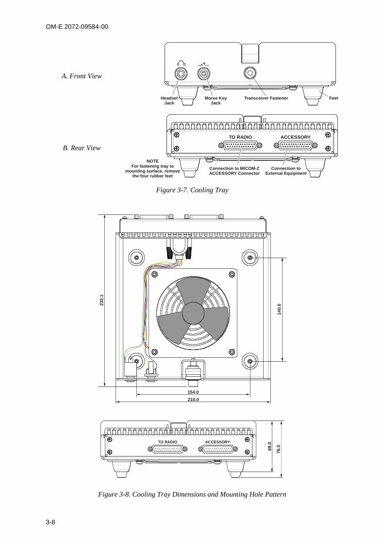
OM-E 2072-09584-00
3-8
A. Front View
Headset Jack
Morse KeyJack
Transceiver Fastener Feet
B. Rear View
TO RADIO ACCESSORY
Connection to MICOM-ZACCESSORY Connector
NOTEFor fastening tray to
mounting surface, remove the four rubber feet
Connection to External Equipment
Figure 3-7. Cooling Tray
232.1
14
0.0
154.0
210.0
TO RADIO ACCESSORY
69.0
76.5
Figure 3-8. Cooling Tray Dimensions and Mounting Hole Pattern
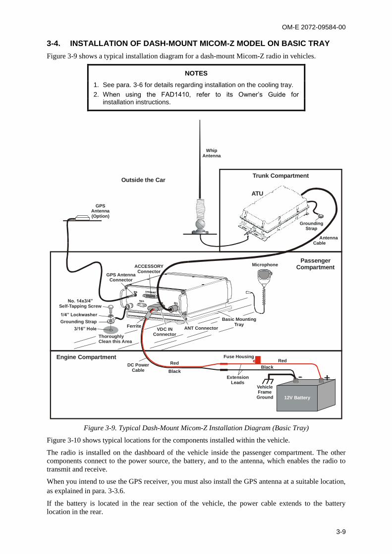
OM-E 2072-09584-00
3-9
3-4. INSTALLATION OF DASH-MOUNT MICOM-Z MODEL ON BASIC TRAY
Figure 3-9 shows a typical installation diagram for a dash-mount Micom-Z radio in vehicles.
NOTES
1. See para. 3-6 for details regarding installation on the cooling tray.
2. When using the FAD1410, refer to its Owner’s Guide for installation instructions.
Fuse Housing
ExtensionLeads
VehicleFrame Ground
ACCESSORYConnector
VDC INConnector
RedRed
BlackBlack
DC Power Cable
Trunk Compartment
Engine Compartment
Passenger Compartment
Outside the Car
ATU
ANT Connector
Grounding Strap
No. 14x3/4”Self-Tapping Screw
ThoroughlyClean this Area
3/16” Hole
1/4” Lockwasher
Microphone
12V Battery
Basic MountingTray
GPS AntennaConnector
GPSAntenna(Option)
WhipAntenna
Ferrite
GroundingStrap
Antenna Cable
Figure 3-9. Typical Dash-Mount Micom-Z Installation Diagram (Basic Tray)
Figure 3-10 shows typical locations for the components installed within the vehicle.
The radio is installed on the dashboard of the vehicle inside the passenger compartment. The other
components connect to the power source, the battery, and to the antenna, which enables the radio to
transmit and receive.
When you intend to use the GPS receiver, you must also install the GPS antenna at a suitable location,
as explained in para. 3-3.6.
If the battery is located in the rear section of the vehicle, the power cable extends to the battery
location in the rear.

OM-E 2072-09584-00
3-10
Radio
ATU
Antenna Cable
DC Power Cable
BAT
GPS Antenna
Figure 3-10. Typical Dash-Mount Micom-Z Installation within Vehicle
NOTE
To achieve maximum operating range, the antenna should be mounted as high on the vehicle body as possible without striking overhead obstructions in the normal service area of the vehicle. Select a mounting location on a flat portion of the vehicle body, compatible with the maximum allowable high voltage lead-in cable length to the ATU.
After determining the locations of the various components within the vehicle, install as follows:
1. Install the whip antenna, or the FAD1410 antenna system, in accordance with the
manufacturer’s installation manual.
2. Install the ATU (when used) in accordance with the manufacturer’s installation manual, and
connect its high-voltage lead to the whip antenna. Make sure to provide a good grounding
connection.
3. Install the Micom-Z mounting tray in the
prescribed location.
Check the mounting surface and the
holes used to attach the mounting tray.
Thoroughly clean the mounting surface
and remove all paint, grease and dirt
from the holes in order to provide a
better grounding connection.
Place the tray in the prescribed location,
and align its holes with the holes on the
mounting surface.
Insert a bolt with springwasher through
each tray hole, and screw it into the
corresponding hole of the mounting
surface. Tighten securely each bolt.
NOTE
If the holes in the mounting surface do not include threaded inserts, use nuts with toothwashers.
Tray
Stop Bar
TransceiverFastener

OM-E 2072-09584-00
3-11
4. Release the transceiver fastener.
5. Insert the transceiver as shown in the
figure, until its rear engages the stop bar of
the tray. Make sure that the transceiver
heatsink fins fit around the fastener sides.
Check that the transceiver sits well within
the tray, and that its heatsink is horizontal
and touches the tray along its whole length.
6. Tighten the fastener with an Allen wrench,
to secure the transceiver safely within the
tray. Fastener
7. Connect the grounding strap to the vehicle body, as shown in Figure 3-9.
8. Route the antenna cable along the prescribed route, passing it through access holes as needed.
9. Connect the antenna cable to the N-type connector of the ATU. Connect the other end of the
cable to the Micom-Z ANT connector.
10. When using the GPS receiver, route the GPS antenna cable along the prescribed route, and
connect its connector to the GPS connector on the Micom-Z rear panel.
11. Check the fuse installed in the red extension lead.
12. Connect the lugs of the two DC power extension leads to the battery. Pay attention to polarity
(red lead to the positive battery terminal). Make sure the negative pole of the battery is
connected to the vehicle chassis, as close as possible to the transceiver.
13. Install the ferrite supplied in the installation kit on the DC power cable, as close as feasible to
the connector.
14. Connect the DC power cable to the transceiver VDC IN connector, and route the cable to the
battery location, along the prescribed route.
15. Connect the plug of the DC power negative (black) lead to the jack of the black extension lead.
16. When ready to apply DC power, connect the plug of the DC power positive (red) lead to the
jack of the red extension lead.
17. Connect a microphone to the transceiver front panel.
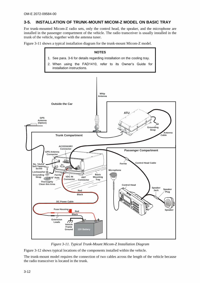
OM-E 2072-09584-00
3-12
3-5. INSTALLATION OF TRUNK-MOUNT MICOM-Z MODEL ON BASIC TRAY
For trunk-mounted Micom-Z radio sets, only the control head, the speaker, and the microphone are
installed in the passenger compartment of the vehicle. The radio transceiver is usually installed in the
trunk of the vehicle, together with the antenna tuner.
Figure 3-11 shows a typical installation diagram for the trunk-mount Micom-Z model.
NOTES
1. See para. 3-6 for details regarding installation on the cooling tray.
2. When using the FAD1410, refer to its Owner’s Guide for installation instructions.
VDC INConnector
Trunk Compartment
Passenger Compartment
ATU
ANT Connector
Microphone
Control Head Cable
Control Head
ACCESSORYConnector
GPS AntennaConnector
GPSAntenna(Option)
Outside the Car
WhipAntenna
BasicMounting
Tray
Fuse Housing
ExtensionLeads
Red
Red
Black
Black
DC Power Cable
12V Battery
Grounding Strap
ThoroughlyClean this Area
Lockwasher
3/16” Hole
No. 14x3/4”Self-Tapping
Screw
VehicleFrame
Ground
Ferrite
Ferrite
GroundingStrap
Antenna Cable
SpeakerJack Speaker
Plug
Speaker
Figure 3-11. Typical Trunk-Mount Micom-Z Installation Diagram
Figure 3-12 shows typical locations of the components installed within the vehicle.
The trunk-mount model requires the connection of two cables across the length of the vehicle because
the radio transceiver is located in the trunk.
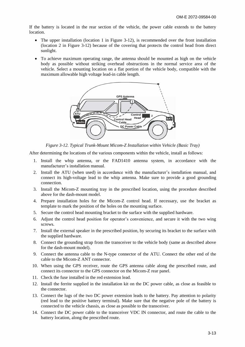
OM-E 2072-09584-00
3-13
If the battery is located in the rear section of the vehicle, the power cable extends to the battery
location.
The upper installation (location 1 in Figure 3-12), is recommended over the front installation
(location 2 in Figure 3-12) because of the covering that protects the control head from direct
sunlight.
To achieve maximum operating range, the antenna should be mounted as high on the vehicle
body as possible without striking overhead obstructions in the normal service area of the
vehicle. Select a mounting location on a flat portion of the vehicle body, compatible with the
maximum allowable high voltage lead-in cable length.
ATU
Radio
1
2
GPS Antenna
ControlHead
DC Power Cable
Control HeadCable
BAT
Figure 3-12. Typical Trunk-Mount Micom-Z Installation within Vehicle (Basic Tray)
After determining the locations of the various components within the vehicle, install as follows:
1. Install the whip antenna, or the FAD1410 antenna system, in accordance with the
manufacturer’s installation manual.
2. Install the ATU (when used) in accordance with the manufacturer’s installation manual, and
connect its high-voltage lead to the whip antenna. Make sure to provide a good grounding
connection.
3. Install the Micom-Z mounting tray in the prescribed location, using the procedure described
above for the dash-mount model.
4. Prepare installation holes for the Micom-Z control head. If necessary, use the bracket as
template to mark the position of the holes on the mounting surface.
5. Secure the control head mounting bracket to the surface with the supplied hardware.
6. Adjust the control head position for operator’s convenience, and secure it with the two wing
screws.
7. Install the external speaker in the prescribed position, by securing its bracket to the surface with
the supplied hardware.
8. Connect the grounding strap from the transceiver to the vehicle body (same as described above
for the dash-mount model).
9. Connect the antenna cable to the N-type connector of the ATU. Connect the other end of the
cable to the Micom-Z ANT connector.
10. When using the GPS receiver, route the GPS antenna cable along the prescribed route, and
connect its connector to the GPS connector on the Micom-Z rear panel.
11. Check the fuse installed in the red extension lead.
12. Install the ferrite supplied in the installation kit on the DC power cable, as close as feasible to
the connector.
13. Connect the lugs of the two DC power extension leads to the battery. Pay attention to polarity
(red lead to the positive battery terminal). Make sure that the negative pole of the battery is
connected to the vehicle chassis, as close as possible to the transceiver.
14. Connect the DC power cable to the transceiver VDC IN connector, and route the cable to the
battery location, along the prescribed route.
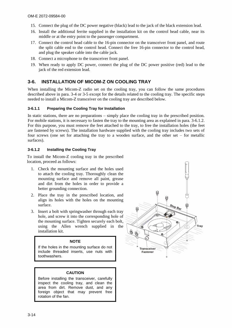
OM-E 2072-09584-00
3-14
15. Connect the plug of the DC power negative (black) lead to the jack of the black extension lead.
16. Install the additional ferrite supplied in the installation kit on the control head cable, near its
middle or at the entry point to the passenger compartment.
17. Connect the control head cable to the 16-pin connector on the transceiver front panel, and route
the split cable end to the control head. Connect the free 16-pin connector to the control head,
and plug the speaker cable into the cable jack.
18. Connect a microphone to the transceiver front panel.
19. When ready to apply DC power, connect the plug of the DC power positive (red) lead to the
jack of the red extension lead.
3-6. INSTALLATION OF MICOM-Z ON COOLING TRAY
When installing the Micom-Z radio set on the cooling tray, you can follow the same procedures
described above in para. 3-4 or 3-5 except for the details related to the cooling tray. The specific steps
needed to install a Micom-Z transceiver on the cooling tray are described below.
3-6.1.1 Preparing the Cooling Tray for Installation
In static stations, there are no preparations – simply place the cooling tray in the prescribed position.
For mobile stations, it is necessary to fasten the tray to the mounting area as explained in para. 3-6.1.2.
For this purpose, you must remove the feet attached to the tray, to free the installation holes (the feet
are fastened by screws). The installation hardware supplied with the cooling tray includes two sets of
four screws (one set for attaching the tray to a wooden surface, and the other set – for metallic
surfaces).
3-6.1.2 Installing the Cooling Tray
To install the Micom-Z cooling tray in the prescribed
location, proceed as follows:
1. Check the mounting surface and the holes used
to attach the cooling tray. Thoroughly clean the
mounting surface and remove all paint, grease
and dirt from the holes in order to provide a
better grounding connection.
2. Place the tray in the prescribed location, and
align its holes with the holes on the mounting
surface.
3. Insert a bolt with springwasher through each tray
hole, and screw it into the corresponding hole of
the mounting surface. Tighten securely each bolt,
using the Allen wrench supplied in the
installation kit.
NOTE
If the holes in the mounting surface do not include threaded inserts, use nuts with toothwashers.
CAUTION
Before installing the transceiver, carefully inspect the cooling tray, and clean the area from dirt. Remove dust, and any foreign object that may prevent free rotation of the fan.
Tray
TransceiverFastener
OM-E 2072-09584-00
3-15
4. Release the transceiver fastener, and insert the transceiver until its rear engages the stop bar of
the tray. Make sure that the transceiver heatsink fins fit around the fastener sides. Check that
the transceiver sits well within the tray, and that its heatsink is horizontal and touches the tray
along its whole length.
5. Tighten the fastener with an Allen wrench, to secure the transceiver safely within the tray.
6. Connect the grounding strap to the vehicle body, as shown in Figure 3-9 or Figure 3-11.
7. Connect the 44-pin/25-pin adapter cable between the ACCESSORY connector of the
transceiver and the TO RADIO connector on the cooling tray.
3-6.1.3 Connecting to the Cooling Tray
At this stage, you may start connecting cables to the transceiver as explained in para. 3-4 or 3-5,
respectively. The only differences are as follows:
1. Connect the equipment to the ACCESSORY connector on the cooling tray, instead of the
connector located on the transceiver.
2. You can connect a headphone set and a telegraphy (Morse) key to the corresponding front jacks
of the cooling tray.
3-7. CHECKING INSTALLED EQUIPMENT
The purpose of the checks is to verify that the equipment has been properly installed and is ready for
communication.
If a problem is detected during the checks, use para. 3-7.2 to identify the source and return the
equipment as soon as possible to operational condition, by replacing cables, accessories, or equipment
units suspected of being defective.
3-7.1 Operational Checks
When installation is complete, perform a visual inspection, to ensure that the radio equipment and the
antenna system have been properly installed, and then carefully check all the operational functions of
the radio set. Whenever possible, perform a communication check with one of the other radio stations
in your net.
When using the cooling tray, make sure that the fan rotates freely, without any unusual noises (upon
power-up, the fan is automatically activated for 10 seconds).
3-7.2 What to Do If ...
3-7.2.1 Preliminary Checks
In case a problem is detected, or the radio set fails to operate, perform the following steps:
1. Visually inspect the radio set, and make sure that the radio set is assembled properly and ready
for operation. Also check that all the accessories are properly connected.
2. In static installations, replace or recharge the battery. The first time a new battery is used, it
should be charged for at least 16 hours.
3. Check the antenna system and its connections. In particular, for whip antennas check that the
whip is screwed on properly, with its base flush against the top of the antenna base or matching
unit.
4. Pay attention to any fault messages that may appear on the Micom-Z display, either upon
power-up or during operation, and refer to para. 3-7.2.2 for instructions.
If the problem persists, identify the closest description appearing in Table 3-1 and then perform the
listed corrective actions until the problem disappears. If problem persists, refer to para. 3-7.2.3.
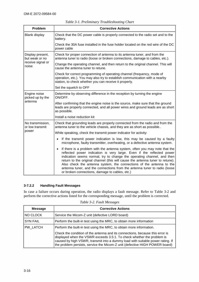
OM-E 2072-09584-00
3-16
Table 3-1. Preliminary Troubleshooting Chart
Problem Corrective Actions
Blank display Check that the DC power cable is properly connected to the radio set and to the battery.
Check the 30A fuse installed in the fuse holder located on the red wire of the DC power cable
Display present, but weak or no receive signal or noise
Check for proper connection of antenna to its antenna tuner, and from the antenna tuner to radio (loose or broken connections, damage to cables, etc.).
Change the operating channel, and then return to the original channel. This will cause the antenna tuner to retune.
Check for correct programming of operating channel (frequency, mode of operation, etc.). You may also try to establish communication with a nearby station, to check whether you can receive it properly.
Set the squelch to OFF
Engine noise picked up by the antenna
Determine by observing difference in the reception by turning the engine ON/OFF.
After confirming that the engine noise is the source, make sure that the ground leads are properly connected, and all power wires and ground leads are as short as possible.
Install a noise reduction kit
No transmission, or low transmit power
Check that grounding leads are properly connected from the radio and from the antenna tuner to the vehicle chassis, and they are as short as possible..
While speaking, check the transmit power indicator for activity:
If the transmit power indication is low, this may be caused by a faulty microphone, faulty transmitter, overheating, or a defective antenna system.
If there is a problem with the antenna system, often you may note that the reflected power indication is very large. Even if the reflected power indication seems normal, try to change the operating channel, and then return to the original channel (this will cause the antenna tuner to retune). Also check the antenna system, the connections of the antenna to the antenna tuner, and the connections from the antenna tuner to radio (loose or broken connections, damage to cables, etc.)
3-7.2.2 Handling Fault Messages
In case a failure occurs during operation, the radio displays a fault message. Refer to Table 3-2 and
perform the corrective actions listed for the corresponding message, until the problem is corrected.
Table 3-2. Fault Messages
Message Corrective Actions
NO CLOCK Service the Micom-Z unit (defective LORD board)
SYN FAIL Perform the built-in test using the MRC, to obtain more information
PW_LATCH Perform the built-in test using the MRC, to obtain more information.
Check the condition of the antenna and its connections, because this error is displayed when the VSWR exceeds 3.5:1. To check whether the problem is caused by high VSWR, transmit into a dummy load with suitable power rating. If the problem persists, service the Micom-Z unit (defective HIGH POWER board)
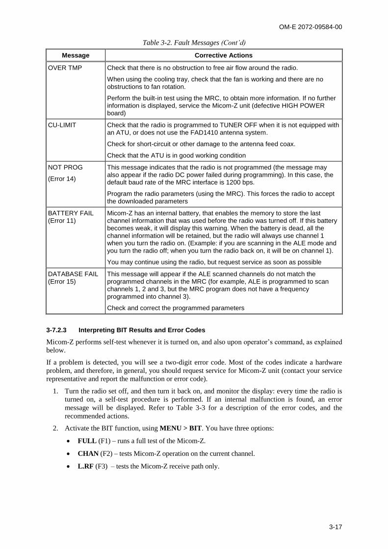
OM-E 2072-09584-00
3-17
Table 3-2. Fault Messages (Cont’d)
Message Corrective Actions
OVER TMP Check that there is no obstruction to free air flow around the radio.
When using the cooling tray, check that the fan is working and there are no obstructions to fan rotation.
Perform the built-in test using the MRC, to obtain more information. If no further information is displayed, service the Micom-Z unit (defective HIGH POWER board)
CU-LIMIT Check that the radio is programmed to TUNER OFF when it is not equipped with an ATU, or does not use the FAD1410 antenna system.
Check for short-circuit or other damage to the antenna feed coax.
Check that the ATU is in good working condition
NOT PROG
(Error 14)
This message indicates that the radio is not programmed (the message may also appear if the radio DC power failed during programming). In this case, the default baud rate of the MRC interface is 1200 bps.
Program the radio parameters (using the MRC). This forces the radio to accept the downloaded parameters
BATTERY FAIL (Error 11)
Micom-Z has an internal battery, that enables the memory to store the last channel information that was used before the radio was turned off. If this battery becomes weak, it will display this warning. When the battery is dead, all the channel information will be retained, but the radio will always use channel 1 when you turn the radio on. (Example: if you are scanning in the ALE mode and you turn the radio off; when you turn the radio back on, it will be on channel 1).
You may continue using the radio, but request service as soon as possible
DATABASE FAIL (Error 15)
This message will appear if the ALE scanned channels do not match the programmed channels in the MRC (for example, ALE is programmed to scan channels 1, 2 and 3, but the MRC program does not have a frequency programmed into channel 3).
Check and correct the programmed parameters
3-7.2.3 Interpreting BIT Results and Error Codes
Micom-Z performs self-test whenever it is turned on, and also upon operator’s command, as explained
below.
If a problem is detected, you will see a two-digit error code. Most of the codes indicate a hardware
problem, and therefore, in general, you should request service for Micom-Z unit (contact your service
representative and report the malfunction or error code).
1. Turn the radio set off, and then turn it back on, and monitor the display: every time the radio is
turned on, a self-test procedure is performed. If an internal malfunction is found, an error
message will be displayed. Refer to Table 3-3 for a description of the error codes, and the
recommended actions.
2. Activate the BIT function, using MENU > BIT. You have three options:
FULL (F1) – runs a full test of the Micom-Z.
CHAN (F2) – tests Micom-Z operation on the current channel.
L.RF (F3) – tests the Micom-Z receive path only.
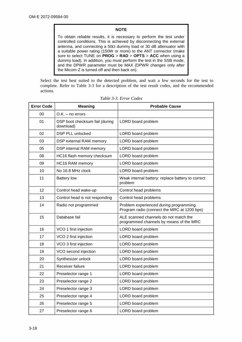
OM-E 2072-09584-00
3-18
NOTE
To obtain reliable results, it is necessary to perform the test under controlled conditions. This is achieved by disconnecting the external
antenna, and connecting a 50 dummy load or 30 dB attenuator with a suitable power rating (150W or more) to the ANT connector (make sure to select TUNE on PROG > RAD > OPTS > ACC when using a dummy load). In addition, you must perform the test in the SSB mode, and the DPWR parameter must be MAX (DPWR changes only after the Micom-Z is turned off and then back on).
Select the test best suited to the detected problem, and wait a few seconds for the test to
complete. Refer to Table 3-3 for a description of the test result codes, and the recommended
actions.
Table 3-3. Error Codes
Error Code Meaning Probable Cause
00 O.K. – no errors
01 DSP boot checksum fail (during download)
LORD board problem
02 DSP PLL unlocked LORD board problem
03 DSP external RAM memory LORD board problem
05 DSP internal RAM memory LORD board problem
08 HC16 flash memory checksum LORD board problem
09 HC16 RAM memory LORD board problem
10 No 16.8 MHz clock LORD board problem
11 Battery low Weak internal battery: replace battery to correct problem
12 Control head wake-up Control head problems
13 Control head is not responding Control head problems
14 Radio not programmed Problem experienced during programming. Program radio (connect the MRC at 1200 bps)
15 Database fail ALE scanned channels do not match the programmed channels by means of the MRC
16 VCO 1 first injection LORD board problem
17 VCO 2 first injection LORD board problem
18 VCO 3 first injection LORD board problem
19 VCO second injection LORD board problem
20 Synthesizer unlock LORD board problem
21 Receiver failure LORD board problem
22 Preselector range 1 LORD board problem
23 Preselector range 2 LORD board problem
24 Preselector range 3 LORD board problem
25 Preselector range 4 LORD board problem
26 Preselector range 5 LORD board problem
27 Preselector range 6 LORD board problem

OM-E 2072-09584-00
3-19
Table 3-3. Error Codes (Cont’d)
Error Code Meaning Probable Cause
28 Preselector range 7 LORD board problem
29 Preselector range 8 LORD board problem
30 Exciter test HIGH POWER board problem
31 Antenna mismatch Problem with antenna: check antenna and its connections. If problem persists, it is a HIGH POWER board problem
32 Harmonic filter range 1 HIGH POWER board problem
33 Harmonic filter range 2 HIGH POWER board problem
34 Harmonic filter range 3 HIGH POWER board problem
35 Harmonic filter range 4 HIGH POWER board problem
36 Harmonic filter range 5 HIGH POWER board problem
37 Harmonic filter range 6 HIGH POWER board problem
38 Harmonic filter range 7 HIGH POWER board problem
39 Power amplifier failure HIGH POWER board problem
OM-E 2072-09584-00
4-1
CHAPTER 4
USING THE PROGRAMMING MODE
4-1. SCOPEThis Chapter provides concise instructions for using the PROG mode.
The Programming mode, accessed by opening the PROG menu is used to program manually theparameters needed by your radio set. There are three main group of parameters:
Radio parameters – the parameters for communication in your environment and in the radio netsyou use most of the time. Refer to para. 4-3 for details.
ALE parameters – the parameters needed to use the ALE function. Refer to para. 4-4 for details.
CCIR parameters – the parameters needed to use the CCIR function. Refer to para. 4-5 fordetails.
The manufacturer offers a dedicated Radio Service Software (MRC), which is an efficient tool forpreparing sets of operational parameters for Micom-Z radio. MRC supports all the functions that canbe performed by means of the PROG menu. MRC is recommended when it is necessary to configuremany radio sets.
Micom-Z lets you change the most of parameters in use on-line, to adjust to any particular situation.However, when you select another channel or net, the changes are discarded and the programmedvalues are used again.
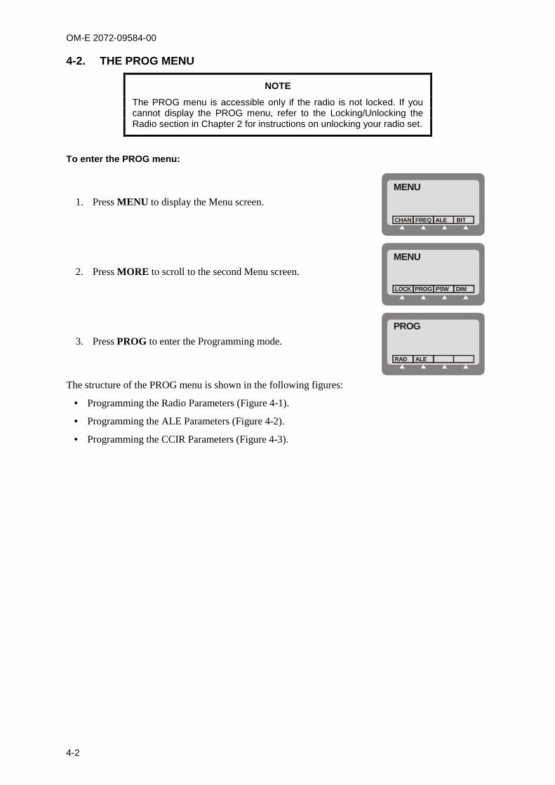
OM-E 2072-09584-00
4-2
4-2. THE PROG MENU
NOTE
The PROG menu is accessible only if the radio is not locked. If youcannot display the PROG menu, refer to the Locking/Unlocking theRadio section in Chapter 2 for instructions on unlocking your radio set.
To enter the PROG menu:
1. Press MENU to display the Menu screen.
MENU
FREQCHAN ALE BIT
2. Press MORE to scroll to the second Menu screen.
MENU
PROGLOCK PSW DIM
3. Press PROG to enter the Programming mode.
PROG
ALERAD
The structure of the PROG menu is shown in the following figures:
Programming the Radio Parameters (Figure 4-1).
Programming the ALE Parameters (Figure 4-2).
Programming the CCIR Parameters (Figure 4-3).

OM-E 2072-09584-00
4-3
4-3. PROGRAMMING THE RADIO PARAMETERSThe Radio (RAD) Programming menu is used to program the following types of parameters:
Channel parameters – para. 4-3.1
General radio parameters – para. 4-3.2.
Radio options – para. 4-3.3.
Refer to Figure 4-1 for the detailed structure and options of the RAD menu.
CHAN
RAD
PRMT OPTS
ALECCIRNONESET
ACC SLCL
TUNENONE
DPWRBAUD MST AST PTBP KBBP TONE ATTNADT CW DIMRCLV
YESNO
STORGET ERAS PWR FREQ BAND MODE BWAGC
YESNO
YESNO
YESNO
LOWHIGH
YESNO
0.250.50.8
YESNO
YESNO
1.22.44.89.6
LOWMEDHIGHMAX
SMPXDPLXRXOTXO
LSBUSB
SSBAMEPLT
SLOWFASTOFF
HS2.73.03.3LSMCW
1
10
.....
CCIR
....
PROGMain MenuMORE
MORE
MORE
MORE
MORE
CHNM
1......
ALE
....
or
LOWMEDHIMAX
Figure 4-1. PROG Menu – Radio Parameters Programming
The following sections explain the programming procedures.
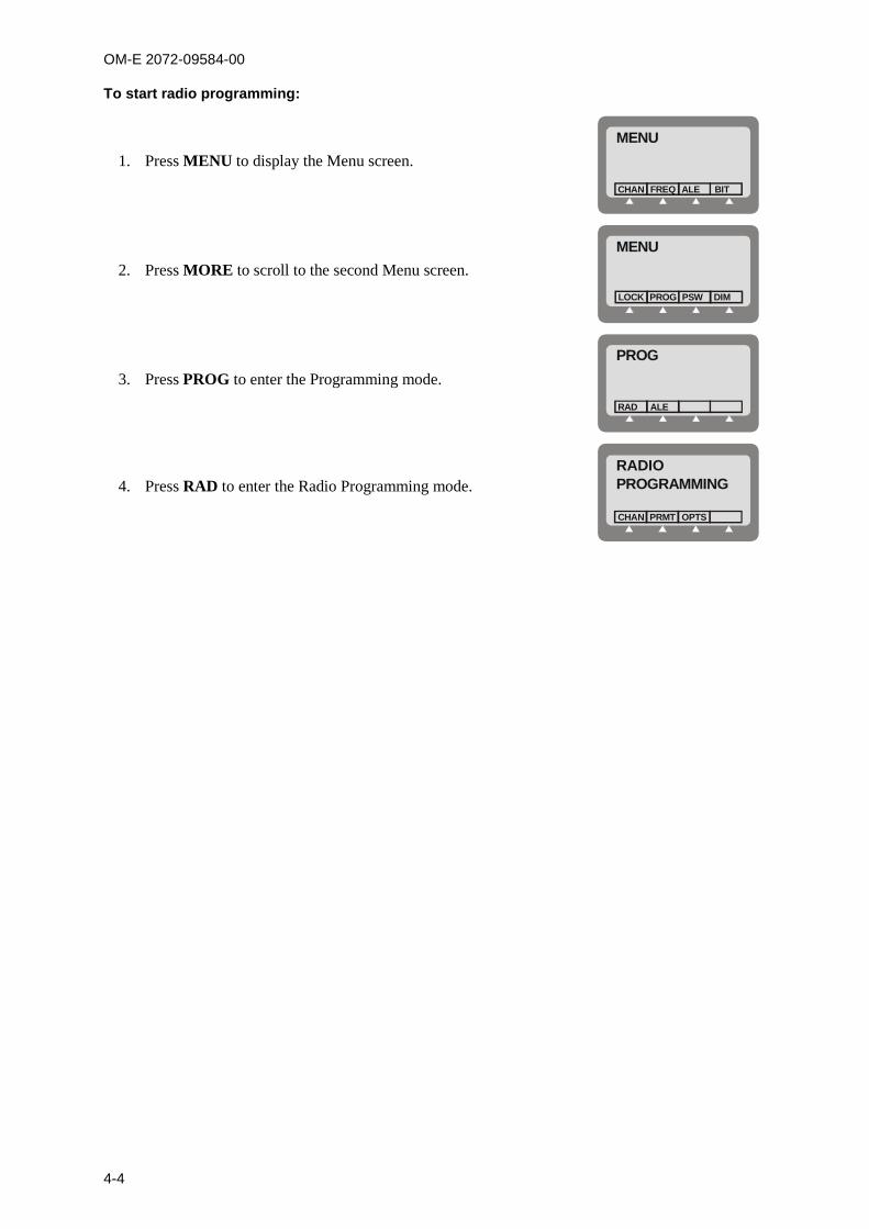
OM-E 2072-09584-00
4-4
To start radio programming:
1. Press MENU to display the Menu screen.
MENU
FREQCHAN ALE BIT
2. Press MORE to scroll to the second Menu screen.
MENU
PROGLOCK PSW DIM
3. Press PROG to enter the Programming mode.
PROG
ALERAD
4. Press RAD to enter the Radio Programming mode.RADIOPROGRAMMING
PRMTCHAN OPTS
OM-E 2072-09584-00
4-5
4-3.1 Programming Channels
The Channel programming menu includes two groups of options:
GET and STOR are used to copy the channel parameters from one selected channel to another,and ERAS is used to delete the user-configured parameters of a selected channel.
The other options are used to configure the operational parameters to be used on the channelbeing configured.
To enter the Channel Programming mode:
1. Enter the Radio Programming menu.
2. Press CHAN.
The CHAN menu provides the following options (see also Figure 4-1):
Option Description
GET GET retrieves all the parameters defined for a channel already programmed in Micom-Z(the default is the current channel, but you can select any other channel).
You can store these parameters in a new channel using the STOR function, and then editthe parameters as required.
STOR Store the set of parameters in a selected channel.
ERAS ERAS is used to delete (erase) a channel. Actually, this action only replaces the user-modified parameters of the channel with the factory-default parameters, but marks thechannel as not programmed.
The factory-default parameter values are as follows: Rx Frequency 15.000.00 MHz Tx Frequency 15.000.00 MHz SSB Mode USB Bandwidth 2.7 Tx Power MAX AGC SLOW.
PWR Select the channel transmit power level. Four transmit power levels can be selected:
LOW – 25 W nominal
MED – 60 W nominal
HIGH – 100 W nominal
MAX – 125 W nominal.
FREQ Select the channel frequency. Micom-Z offers four frequency options:
SMPX Simplex Frequency – the same frequency is used for both transmissionand reception.
DPLX Duplex Frequency – transmits on one frequency and receives on adifferent frequency.
RXO Receiving Only Frequency – defines a frequency for reception only.Transmission on that frequency is disabled. The available frequency rangeis 100 kHz to 30 MHz.
TXO Transmitting Only Frequency – defines a frequency for transmission only.You cannot receive on that frequency. The available frequency range is1.6 to 30 MHz.
BAND Select the channel operating sideband: USB – upper sideband mode LSB – lower sideband mode.
OM-E 2072-09584-00
4-6
Option Description
MODE Select the channel radio operating mode: SSB – single sideband AME – amplitude modulation equivalent PLT – single sideband with pilot signal.
AGC Select the channel Automatic Gain Control mode. Micom-Z offers two AGC responsespeeds: SLOW and FAST. You can also turn the AGC OFF completely.
BW Selects the filter bandwidth. HS – high sensitivity filter (450 to 1500 Hz) for best voice communication under
marginal conditions 2.7 – 300 to 2700 Hz 3.0 – 300 to 3000 Hz 3.3 – 300 to 3300 Hz. Always select this bandwidth for data transmission LSM – bandwidth optimized for use with low speed modems (1450 to 1950 Hz) CW (Continuous Wave or Morse operation). The bandwidth used in this case is
selected by MENU > PROG > RAD > PRMT > CW.
4-3.2 Configuring Radio Parameters
The radio parameters are global parameters, which are used for all the channels.
To start the radio parameters programming:
1. Enter the Radio Programming menu.
2. Press PRMT.
The PRMT option in the Radio Programming menu provides the following options (see Figure 4-1):
Option Description
BAUD Selects the data transmission rate of the internal modem: 1.2 – 1200 bps 2.4 – 2400 bps 4.8 – 4800 bps 9.6 – 9600 bps.
DPWR Selects the maximum transmit power for data transmission, that is, for a transmissioninitiated by the data PTT. The available selections are: LOW – 25 W nominal MED – 60 W nominal HIGH – 100 W nominal MAX – 125 W nominal.
The transmit power used in the other modes is independently selected for each channel.If the selected data transmit power exceeds the transmit power configured on theoperating channel, the radio will use the lower channel transmit power.
When operating the radio without the optional cooling tray, it is recommended to use thelower power settings (LOW or MED).
MST Enables/disables the sidetone heard in the speaker when you transmit using themicrophone.
AST Enables/disables the heard in the speaker sidetone when you transmit using anaccessory connected through the rear panel.
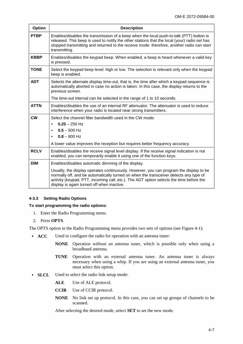
OM-E 2072-09584-00
4-7
Option Description
PTBP Enables/disables the transmission of a beep when the local push-to-talk (PTT) button isreleased. This beep is used to notify the other stations that the local (your) radio set hasstopped transmitting and returned to the receive mode: therefore, another radio can starttransmitting.
KBBP Enables/disables the keypad beep. When enabled, a beep is heard whenever a valid keyis pressed.
TONE Select the keypad beep level: high or low. The selection is relevant only when the keypadbeep is enabled.
ADT Selects the alternate display time-out, that is, the time after which a keypad sequence isautomatically aborted in case no action is taken. In this case, the display returns to theprevious screen.
The time-out interval can be selected in the range of 1 to 10 seconds.
ATTN Enables/disables the use of an internal RF attenuator. The attenuator is used to reduceinterference when your radio is located near strong transmitters.
CW Select the channel filter bandwidth used in the CW mode: 0.25 – 250 Hz 0.5 – 500 Hz 0.8 – 800 Hz
A lower value improves the reception but requires better frequency accuracy.
RCLV Enables/disables the receive signal level display. If the receive signal indication is notenabled, you can temporarily enable it using one of the function keys.
DIM Enables/disables automatic dimming of the display.
Usually, the display operates continuously. However, you can program the display to benormally off, and be automatically turned on when the transceiver detects any type ofactivity (keypad, PTT, incoming call, etc.). The ADT option selects the time before thedisplay is again turned off when inactive.
4-3.3 Setting Radio Options
To start programming the radio options:
1. Enter the Radio Programming menu.
2. Press OPTS.
The OPTS option in the Radio Programming menu provides two sets of options (see Figure 4-1):
ACC Used to configure the radio for operation with an antenna tuner:
NONE Operation without an antenna tuner, which is possible only when using abroadband antenna.
TUNE Operation with an external antenna tuner. An antenna tuner is alwaysnecessary when using a whip. If you are using an external antenna tuner, youmust select this option.
SLCL Used to select the radio link setup mode:
ALE Use of ALE protocol.
CCIR Use of CCIR protocol.
NONE No link set up protocol. In this case, you can set up groups of channels to bescanned.
After selecting the desired mode, select SET to set the new mode.
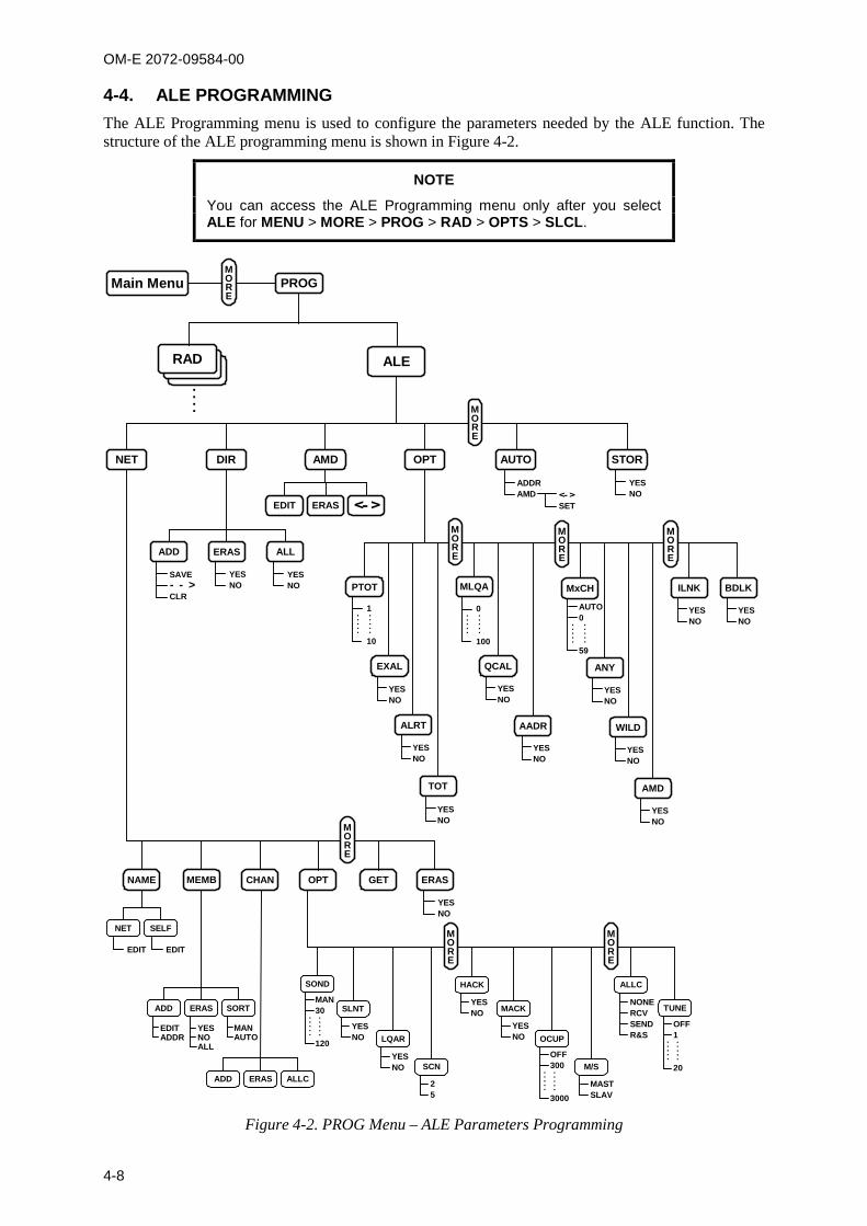
OM-E 2072-09584-00
4-8
4-4. ALE PROGRAMMINGThe ALE Programming menu is used to configure the parameters needed by the ALE function. Thestructure of the ALE programming menu is shown in Figure 4-2.
NOTE
You can access the ALE Programming menu only after you selectALE for MENU > MORE > PROG > RAD > OPTS > SLCL.
MASTSLAV
25
YESNO
MEMBNAME CHAN OPT GET ERAS
NET SELF
ADD ERAS ALLC
ADD ERAS SORT
SOND
SLNT
LQAR
SCN
HACK
MACK
OCUP
M/S
ALLC
TUNE
YESNO
YESNO
YESNO
YESNO
MAN30
120
.....
.....
OFF300
3000
.....
.....
NONERCVSENDR&S
OFF1
20
.....
.....
EDITADDR
MANAUTO
YESNOALL
MORE
MORE
MORE
NET DIR OPT AUTO STOR
ADDRAMD
YESNO
YESNO
ADD ERAS
AMD
EDIT ERAS
ALERAD
....
EDIT EDIT
PROGMain MenuMORE
MORE
SAVE
CLR MxCH
AUTO0
59
.....
.....
YESNO
EXAL
YESNO
ALRT
YESNO
TOT
MLQA
0
100
.....
.....
YESNO
QCAL
YESNO
AADR
YESNO
ANY
YESNO
WILD
YESNO
AMD
YESNO
ILNK
1
10
.....
.....
PTOT
YESNO
BDLK
MORE
MORE
MORE
<- >
ALL
YESNO
<- >SET
Figure 4-2. PROG Menu – ALE Parameters Programming
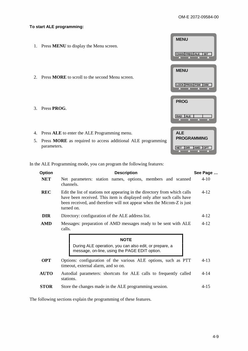
OM-E 2072-09584-00
4-9
To start ALE programming:
1. Press MENU to display the Menu screen.
MENU
FREQCHAN ALE BIT
2. Press MORE to scroll to the second Menu screen.
MENU
PROGLOCK PSW DIM
3. Press PROG.
PROG
ALERAD
4. Press ALE to enter the ALE Programming menu.
5. Press MORE as required to access additional ALE programmingparameters.
ALEPROGRAMMING
DIRNET OPTAMD
In the ALE Programming mode, you can program the following features:
Option Description See Page …NET Net parameters: station names, options, members and scanned
channels.4-10
REC Edit the list of stations not appearing in the directory from which callshave been received. This item is displayed only after such calls havebeen received, and therefore will not appear when the Micom-Z is justturned on.
4-12
DIR Directory: configuration of the ALE address list. 4-12
AMD Messages: preparation of AMD messages ready to be sent with ALEcalls.
NOTEDuring ALE operation, you can also edit, or prepare, amessage, on-line, using the PAGE EDIT option.
4-12
OPT Options: configuration of the various ALE options, such as PTTtimeout, external alarm, and so on.
4-13
AUTO Autodial parameters: shortcuts for ALE calls to frequently calledstations.
4-14
STOR Store the changes made in the ALE programming session. 4-15
The following sections explain the programming of these features.
OM-E 2072-09584-00
4-10
NOTES
The ESC key is used to cancel a change you have made, if not yetconfirmed. If you have already saved changes, the ESC key willonly return to a previous screen of the ALE Programming menu.
When you end ALE programming, you must store the parametersyou defined.
If you press the MENU key to exit the programming mode withoutfirst saving your changes, you will be prompted to store the ALEconfiguration changes. Press YES to store the configuration. If youpress NO, the configuration will revert to the previousconfiguration, and any changes made in the current ALEprogramming session will be ignored.
4-4.1 Programming Nets
When programming a net, you can set the net names, define the net members, add channels, configurevarious options, copy parameters from a defined net or erase an entire net.
4-4.1.1 Overview of Net Programming
The net programming mode enables you to view and edit the configuration of each net. Theconfiguration includes the following menus:
NAME Edit the net name and the self-address:
NET: Define or edit the net names.
It is not allowed to use a name already used as a self-address, nor an addressalready appearing in the address directory.
SELF: Define or edit your self address (the identification of your station, to beused by other stations within the same net).
It is not allowed to use a name already used as a net address, nor an addressalready appearing in the address directory.
A net name or self address can contain up to 15 characters. Valid characters are theletters A to Z and the numerals 0 to 9.
MEMB Add or erase members (station addresses) from the list of net members. This listdefines which stations can participate in a net call (a net can have up to 16addresses).
The MEMB menu also enables you to sort the list of members: this determines theorder in which members respond to a net call. You can arrange the order of the listof members manually, or instruct the radio to arrange them in alphanumeric order.
A member name can contain up to 15 characters. Valid characters are the lettersA to Z and the numerals 0 to 9. It is not allowed to define a name already used as anet address, nor an address already appearing in the address directory. New membernames will automatically be added to the directory list (unless the directory is full).
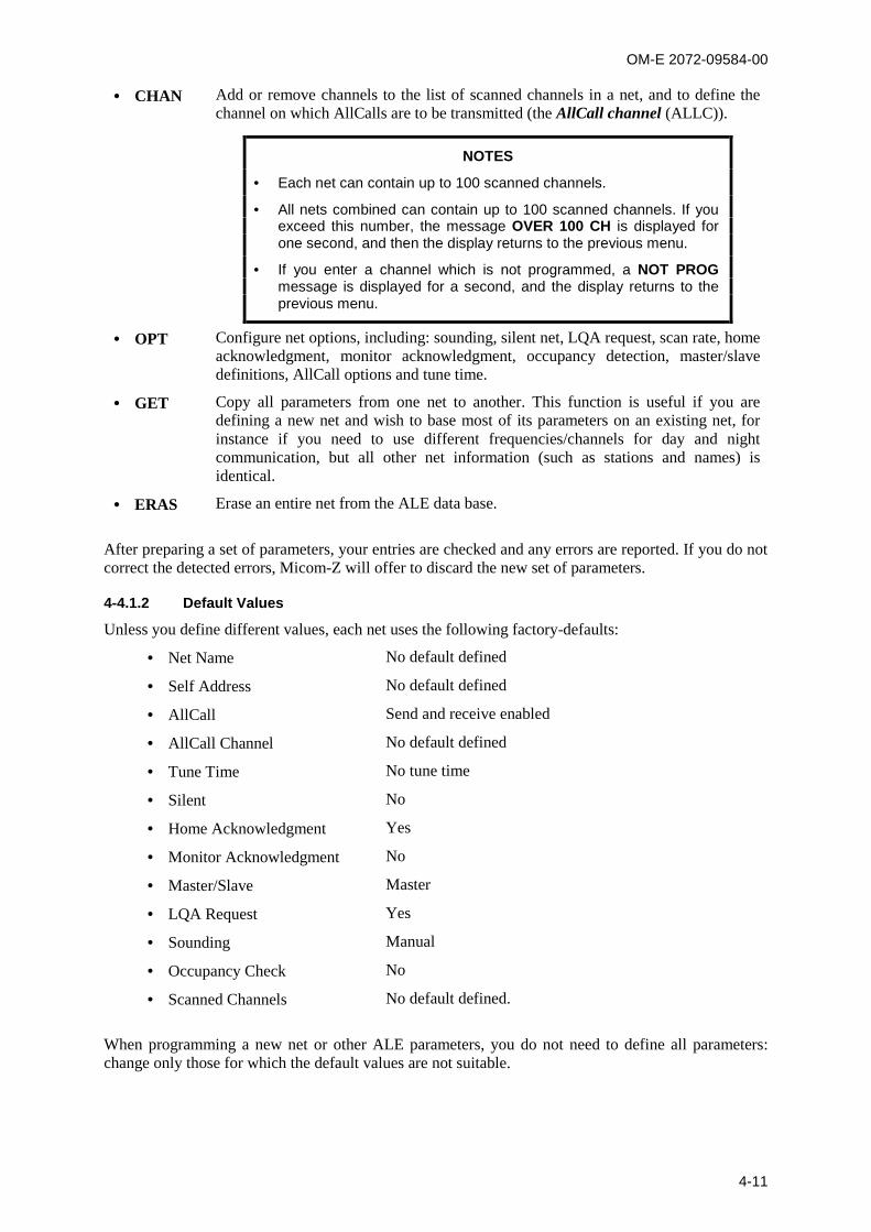
OM-E 2072-09584-00
4-11
CHAN Add or remove channels to the list of scanned channels in a net, and to define thechannel on which AllCalls are to be transmitted (the AllCall channel (ALLC)).
NOTES
Each net can contain up to 100 scanned channels.
All nets combined can contain up to 100 scanned channels. If youexceed this number, the message OVER 100 CH is displayed forone second, and then the display returns to the previous menu.
If you enter a channel which is not programmed, a NOT PROGmessage is displayed for a second, and the display returns to theprevious menu.
OPT Configure net options, including: sounding, silent net, LQA request, scan rate, homeacknowledgment, monitor acknowledgment, occupancy detection, master/slavedefinitions, AllCall options and tune time.
GET Copy all parameters from one net to another. This function is useful if you aredefining a new net and wish to base most of its parameters on an existing net, forinstance if you need to use different frequencies/channels for day and nightcommunication, but all other net information (such as stations and names) isidentical.
ERAS Erase an entire net from the ALE data base.
After preparing a set of parameters, your entries are checked and any errors are reported. If you do notcorrect the detected errors, Micom-Z will offer to discard the new set of parameters.
4-4.1.2 Default Values
Unless you define different values, each net uses the following factory-defaults:
Net Name No default defined
Self Address No default defined
AllCall Send and receive enabled
AllCall Channel No default defined
Tune Time No tune time
Silent No
Home Acknowledgment Yes
Monitor Acknowledgment No
Master/Slave Master
LQA Request Yes
Sounding Manual
Occupancy Check No
Scanned Channels No default defined.
When programming a new net or other ALE parameters, you do not need to define all parameters:change only those for which the default values are not suitable.

OM-E 2072-09584-00
4-12
4-4.2 Setting the Net Options
Use this menu to configure net options:
SOND Sounding Parameters: define the interval (in minutes) at which automaticsounding is performed (30, 60, 90 or 120 minutes), or define sounding as amanual function. See Appendix A for a detailed explanation on the soundingprocess.
SLNT Silent Mode: select whether the net is in the silent mode, which means thatmembers in the net can initiate calls but not allowed to respond to an ALEtransmission.
LQAR LQA Reports: select whether your radio will ask the called station for a report onthe quality of the communication every time a call is initiated.
SCN Scan Rate: select the number of channels scanned each second when the radio isin ALE mode: can be set to 2 or 5 channels per second.
HACK Home Acknowledgment: enable/disable home acknowledgment. When enabled,the radio transmits an end-of-call indication to the remote station.
MACK Monitor Acknowledgment: enable/disable monitor acknowledgment. Whenenabled, the radio transmits an accept call indication to the station that initiatedthe call.
OCUP Occupancy Check: enable/disable the occupancy check. The occupancy checkdefines whether the radio uses the speech detect mechanism to determine whethera channel on which a call is about to be made is occupied. If this option is ON, acall cannot be initiated on a channel determined to be occupied. This option canbe operated in addition to the ALE signal detection mechanism.
You can select the interval at which occupancy checks are made (300 to3000 msec, in 300-msec increments).
M/S Master/Slave: select whether your radio serves as a master or slave in the currentALE network. Only a master station can initiate a Net Call.
ALLC AllCall Settings: this option determines whether the ALE is able to receive and/orsend AllCalls.
An AllCall is an ALE broadcast transmission. All stations receiving an AllCall arelinked to the sender, even if they do not recognize the sender’s address. If noAllCall channel is defined, the call will be made on the best channel in the net.
TUNE Tune Time: select the tuning time. Tuning time is the maximum time the currentALE waits for the called station to tune (this is the tune-in time of the slowesttuner in the net). The tune time is added to the calculated response time. Tunetime can be 1 to 20 seconds, or OFF (zero).
4-4.3 Directory Parameters
This DIR option on the ALE Programming menu enables preparing the ALE address list. This listcontains the names of stations to which the radio can address a private call using the ALE. You canadd a new address, and edit an existing address.
A name can contain up to 15 characters. Valid characters are the letters A to Z and the numerals 0 to 9.You cannot add an address which is identical to the name of a programmed net, nor an address alreadyused as a self address in a programmed net. The list can contain up to 100 addresses, and isautomatically sorted in ascending alphanumeric order.
4-4.4 AMD Message Configuration
The AMD option of the ALE Programming menu is used to view, edit, add or erase messages intendedfor transmission. The characters you can enter in messages using the radio keypad are: A to Z, 0 to 9,space, * and #. See message preparation details in Chapter 2.

OM-E 2072-09584-00
4-13
Messages programmed using a remote PC with a standard keyboard can contain all the ASCIIcharacters the range of 20 (hexa) to 5F (hexa).
The message list can contain up to 12 messages, numbered AMD 0 to AMD 11. Each message cancontain up to 90 characters.
NOTE
If no messages are stored, EMPTY will appear in the second displayline.
4-4.5 ALE Options Configuration
This menu enables you to configure the following ALE options:
Option Description
PTOT PTT Timeout: the time (in minutes) which elapses between the moment you release thePTT button, until the ALE disconnects the link. The allowed range is 1 to 10 minutes.
EXAL External Alarm: activate/deactivate the radio external alarm when a call is received.
ALRT Alert tone: enable/disable the generation of an alert tone whenever a link is established.
TOT Accept Link Time-out Time: the radio can be configured to disconnect the linkautomatically if neither the PTT, nor any other key is pressed within 30 seconds from thereception of a call. If Accept Link TOT is set to NO, the received call is acceptedimmediately and automatically.
MLQA Minimum LQA Score: determines the minimum acceptable LQA (Link Quality Analysis)score allowed when trying to establish a link on a specific channel.
If the minimum score is not achieved when the radio attempts to establish a link in theALE mode, the radio will try to establish a link on the scanned channel with the next bestLQA score. At the end of this process, a link will be established on the scan channel withthe best LQA score. If the call is made on a specific channel, the radio ignores theminimum LQA score check.
The allowed range of LQA scores is 0 to 100%. When selecting the minimum LQA score,remember that in accordance with the ALE standards, the maximum LQA score(assigned for receiving an optimum sounding is 70%), and the minimum score is 30%.The score given to a station that did not send any sounding or a station whose soundinghas not been received is also 30%.
QCAL Quick Call: enable/disable initiating a call to the last called address by pressing the MICPTT button twice in rapid sequence (double pressing).
AADR Automatic address: enable/disable automatically adding the source addresses ofincoming calls to the ALE directory.
NOTEIf the directory is full, new addresses will not be added.
MxCH Maximum Scan Channels: this parameter is used to adapt the duration of the callingsignal to the total number of scanned NET, to ensure that communications are notdisrupted. You can select between automatic selection, or select a value in the range of 0to 59 seconds.
ANY AnyCall: enable/disable the sending AnyCalls.
WILD Wildcard: enable/disable the sending wildcard calls.
AMD Automatic Message Display: enable/disable the sending AMD messages.
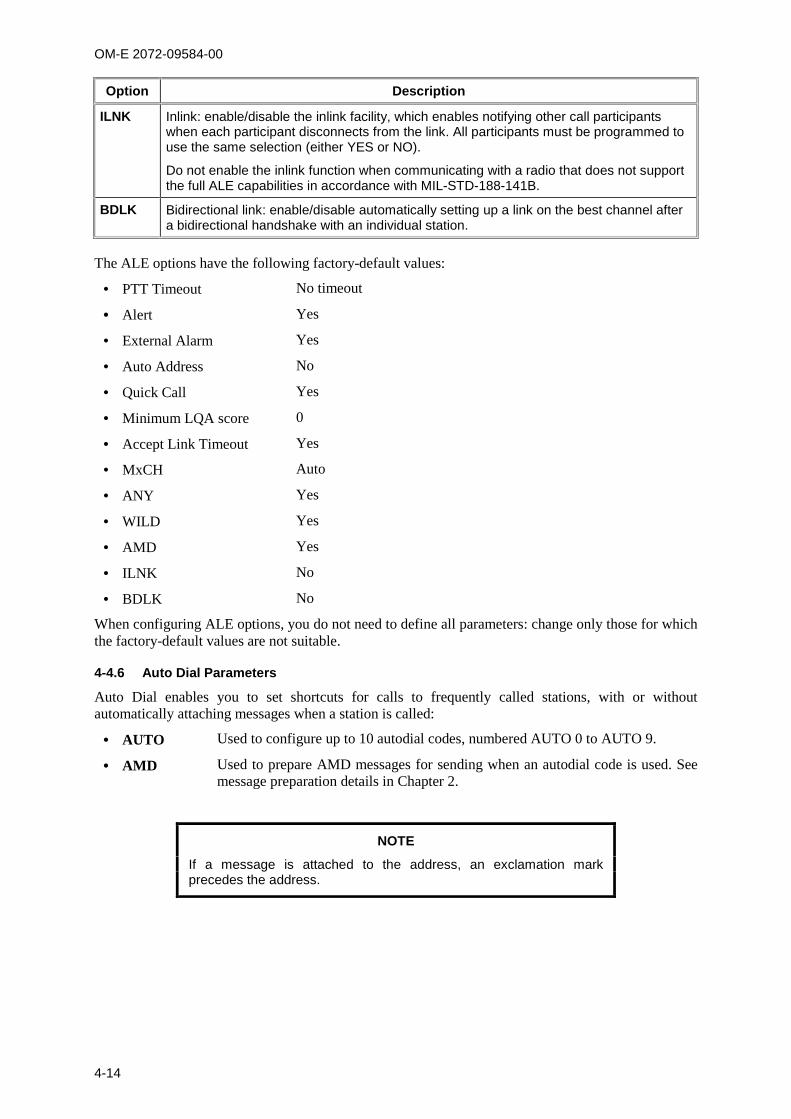
OM-E 2072-09584-00
4-14
Option Description
ILNK Inlink: enable/disable the inlink facility, which enables notifying other call participantswhen each participant disconnects from the link. All participants must be programmed touse the same selection (either YES or NO).
Do not enable the inlink function when communicating with a radio that does not supportthe full ALE capabilities in accordance with MIL-STD-188-141B.
BDLK Bidirectional link: enable/disable automatically setting up a link on the best channel aftera bidirectional handshake with an individual station.
The ALE options have the following factory-default values:
PTT Timeout No timeout
Alert Yes
External Alarm Yes
Auto Address No
Quick Call Yes
Minimum LQA score 0
Accept Link Timeout Yes
MxCH Auto
ANY Yes
WILD Yes
AMD Yes
ILNK No
BDLK No
When configuring ALE options, you do not need to define all parameters: change only those for whichthe factory-default values are not suitable.
4-4.6 Auto Dial Parameters
Auto Dial enables you to set shortcuts for calls to frequently called stations, with or withoutautomatically attaching messages when a station is called:
AUTO Used to configure up to 10 autodial codes, numbered AUTO 0 to AUTO 9.
AMD Used to prepare AMD messages for sending when an autodial code is used. Seemessage preparation details in Chapter 2.
NOTE
If a message is attached to the address, an exclamation markprecedes the address.
OM-E 2072-09584-00
4-15
4-4.7 Storing ALE parameters
Before exiting the ALE programming menu, you must store the parameters you have programmed.
NOTE
If you press the MENU or ESC key to exit programming mode withoutfirst saving your changes, you will be prompted to store the ALEconfiguration changes. Press YES to store the configuration.
If you press NO, the configuration will revert to the previousconfiguration, and any changes made in the ALE programmingsession will be ignored.
4-4.8 Using the New Station Address Filter
To help you add new station addresses to the ALE directory of your radio set in a controlled manner,Micom-Z has a special ALE address filter. To enable this filter, enable the Auto Address function onthe PROG > ALE > OPT > AADR menu (this function can also be enabled by means of the MRC).
When enabled, the address filter compares the source address of each call received by your radio setwith the addresses stored in the ALE directory. When the first new unlisted address is found, it isstored in a special memory stack, and you are notified that at least one unlisted address has beendetected by adding the option RCV under PROG > ALE, after the NET option. When you want tocheck the addresses stored in the stack, you select RCV and then decide whether to erase an address oradd it to the ALE directory of your radio set.
Up to 20 new addresses can be stored in this stack, which is organized as a FIFO stack: this means thatwhen a new address, different from all the previously detected addresses, is received while 20addresses are already stored, it will replace the oldest address.
The information on the received addresses is automatically erased when the radio is turned off; onlyaddresses added to the directory remain in the directory.
To edit the received addresses and add addresses to the ALE directory:
1. Press MENU and select ALE.
2. When addresses are stored in the new received addresses stack, you will see the RCV option.Press RCV to display the RCV screen.
3. The RCV screen displays the last detected unlisted address. Use the UP/DOWN arrows todisplay the desired address (the display is cyclical).
4. When the desired address is displayed, press the key corresponding to the action to beperformed:
To delete the address from the stack, press ERAS.
To add the address to the directory, press ADD. The address is removed from the stack.
5. To confirm, press SAVE.
6. Repeat the actions until all the desired addresses are processed. When done, press ESC to end.
If the stack is now empty, the RCV option is no longer displayed on the ALE menu.
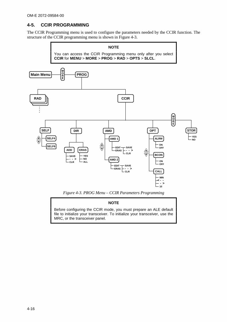
OM-E 2072-09584-00
4-16
4-5. CCIR PROGRAMMINGThe CCIR Programming menu is used to configure the parameters needed by the CCIR function. Thestructure of the CCIR programming menu is shown in Figure 4-3.
NOTE
You can access the CCIR Programming menu only after you selectCCIR for MENU > MORE > PROG > RAD > OPTS > SLCL.
SELF
CCIR
DIR AMD
YESNOALL
RAD
....
PROGMain MenuMORE
OPT
SELF4
SELF6ADD ERAS
AMD 1
AMD 2
ALRM
BCON
CALL
MIN
10
ONOFF
ONOFF
EDITERAS
SAVE
CLR
EDITERAS
SAVE
CLR
SAVE
CLR
STOR
YESNO
MORE
Figure 4-3. PROG Menu – CCIR Parameters Programming
NOTE
Before configuring the CCIR mode, you must prepare an ALE defaultfile to initialize your transceiver. To initialize your transceiver, use theMRC, or the transceiver panel.
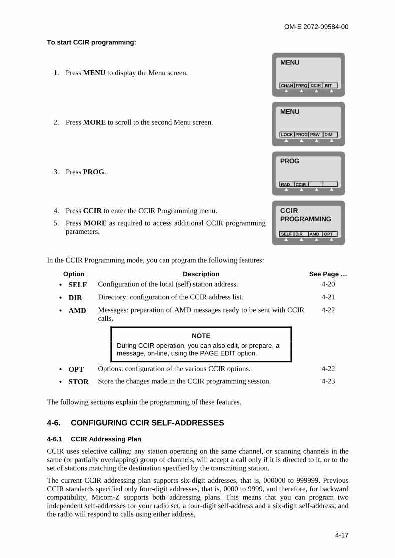
OM-E 2072-09584-00
4-17
To start CCIR programming:
1. Press MENU to display the Menu screen.
MENU
FREQCHAN CCIR BIT
2. Press MORE to scroll to the second Menu screen.
MENU
PROGLOCK PSW DIM
3. Press PROG.
PROG
CCIRRAD
4. Press CCIR to enter the CCIR Programming menu.
5. Press MORE as required to access additional CCIR programmingparameters.
CCIRPROGRAMMING
DIRSELF OPTAMD
In the CCIR Programming mode, you can program the following features:
Option Description See Page … SELF Configuration of the local (self) station address. 4-20
DIR Directory: configuration of the CCIR address list. 4-21
AMD Messages: preparation of AMD messages ready to be sent with CCIRcalls.
NOTEDuring CCIR operation, you can also edit, or prepare, amessage, on-line, using the PAGE EDIT option.
4-22
OPT Options: configuration of the various CCIR options. 4-22
STOR Store the changes made in the CCIR programming session. 4-23
The following sections explain the programming of these features.
4-6. CONFIGURING CCIR SELF-ADDRESSES
4-6.1 CCIR Addressing Plan
CCIR uses selective calling: any station operating on the same channel, or scanning channels in thesame (or partially overlapping) group of channels, will accept a call only if it is directed to it, or to theset of stations matching the destination specified by the transmitting station.
The current CCIR addressing plan supports six-digit addresses, that is, 000000 to 999999. PreviousCCIR standards specified only four-digit addresses, that is, 0000 to 9999, and therefore, for backwardcompatibility, Micom-Z supports both addressing plans. This means that you can program twoindependent self-addresses for your radio set, a four-digit self-address and a six-digit self-address, andthe radio will respond to calls using either address.

OM-E 2072-09584-00
4-18
In addition to individual station addressses, the CCIR addressing plan specifies the following types ofdestination addresses (see Table 4-1 and Table 4-2):
Sub-Group Addresses – addresses ending with a single 0 are directed to a set of stations calledsub-group. When using four-digit addresses, the first three digits of the address determine thesub-group address, whereas when using six-digit addresses, the first five digits of the addressdetermine the sub-group address.
For example, a transceiver with self-address 1234 is included in sub-group 1230, and it willaccept all calls with address 1230.
Group Addresses – addresses ending in two consecutive 0 are directed to a set of stations calledgroup. When using four-digit addresses, the first two digits of the address determine the groupaddress, whereas when using six-digit addresses, the first four digits of the address determine thegroup address.
For example, a transceiver with self-address 1234 is included in group 1200, and it will accept allcalls with address 1200.
All Addresses – addresses ending with in three consecutive 0 are called the all address. Whenusing four-digit addresses, all the stations with the same first digit will accept the all call; whenusing six-digit addresses, all the stations with the same three digits will accept the all call.
Beacon Address – a beacon call is identified by its last two digits, which are 99.
Figure 4-4 and Figure 4-5 illustrate the concept of groups and sub-groups for the two CCIR addressingplans. As a result, when assigning self-addresses to an individual station, never select addresses endingin one or more 0, nor addresses ending in 99. Such addresses are allowed only as destinationaddresses.
Table 4-1. Four-Digit CCIR Addressing Plan
Address Type Description
Sub-Group A call transmitted to XXX0 is received by up to 9 transceivers withindividual addresses in the range of XXX1 to XXX9.
Group A call transmitted to XX00 is received by up to 89 transceivers withindividual addresses in the range of XX01 to XX99.
All A call transmitted to X000 is received by up to 890 transceivers withindividual addresses in the range of X001 to X999.
Beacon A call transmitted to XX99 is interpreted as a beacon call
Table 4-2. Six-Digit CCIR Addressing Plan
Address Type Description
Sub-Group A call transmitted to XXXXX0 is received by up to 9 transceivers withindividual addresses in the range of XXXXX1 to XXXXX9.
Group A call transmitted to XXXX00 is received by up to 89 transceivers withindividual addresses in the range of XXXX01 to XXXX99.
All A call transmitted to XXX000 is received by up to 890 transceivers withindividual addresses in the range of XXX001 to XXX999.
Beacon A call transmitted to XXXX99 is interpreted as a beacon call
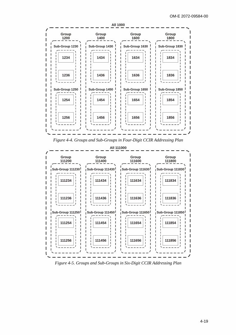
OM-E 2072-09584-00
4-19
1234
1236
1254
1256
1434
1436
1454
1456
1634
1636
1654
1656
1834
1836
1854
1856
Sub-Group 1230
Sub-Group 1250
Sub-Group 1430
Sub-Group 1450
Sub-Group 1630
Sub-Group 1650
Sub-Group 1830
Sub-Group 1850
Group1200
Group1400
All 1000
Group1600
Group1800
Figure 4-4. Groups and Sub-Groups in Four-Digit CCIR Addressing Plan
111234
111236
111254
111256
111434
111436
111454
111456
111634
111636
111654
111656
111834
111836
111854
111856
Sub-Group 111230
Sub-Group 111250
Sub-Group 111430
Sub-Group 111450
Sub-Group 111630
Sub-Group 111650
Sub-Group 111830
Sub-Group 111850
Group111200
Group111400
All 111000
Group111600
Group111800
Figure 4-5. Groups and Sub-Groups in Six-Digit CCIR Addressing Plan

OM-E 2072-09584-00
4-20
4-6.2 Configuring the Self-Address
NOTE
A call transmitted to XXX0, XX00, or X000 is received by multipletransceivers. Therefore, do not configure a self-address with “0”, “00”,or “000” as the last digits.
In addition, a call transmitted to XX99 acts as a beacon call.Therefore, do not configure a self-address with “99” as the last digits.
To configure four-digit self-addresses:
1. Access the CCIR Programming menu: MENU > MORE > PROG > CCIR.
2. Press SELF to access your self-address.
3. Press UP/DOWN keys to scroll to SELF4.
4. Enter the prescribed four-digit self-address. If you enter a self-address with less than four digits,the transceiver automatically converts it to a four-digit self-address. For example, if you enter“1”, then the transceiver automatically converts it to “0001”.
5. Press SAVE to confirm.
6. Press MENU to exit.
7. Press YES to store.
To configure six-digit self-addresses:
1. Access the CCIR Programming menu: MENU > MORE > PROG > CCIR.
2. Press SELF to access your self-address.
3. Press UP/DOWN keys to scroll to SELF6. If you enter a self-address with less than six digits,the transceiver automatically converts it to a six-digit self-address. For example, if you enter“1”, then the transceiver automatically converts it to “000001”.
4. Enter your six-digit self-address.
5. Press SAVE to confirm.
6. Press MENU to exit.
7. Press YES to store.

OM-E 2072-09584-00
4-21
4-6.3 Configuring Directory Entries
This section describes how to configure directory entries. In the CCIR mode, the directory can store upto 100 directory entries.
NOTE
A call transmitted to XX99 acts as a beacon call. Therefore, do notconfigure a directory entry with “99” as the last digits.
To add directory entries:
1. Access the CCIR Programming menu: MENU > MORE > PROG > CCIR.
2. Press DIR to access the Directory menu.
3. Press ADD to add a new directory entry.
NOTE
If you store exactly 100 directory entries, the ADD button disappears.
If you delete one directory entry, the ADD button reappears.
4. Enter the four-digit or six-digit numeric directory entry address.
5. Press SAVE to confirm.
6. If you want to add more directory entries, repeat Step 3 through Step 5.
7. Press MENU to exit.
8. Press YES to store.
To delete directory entries:
1. Access the CCIR Programming menu: MENU > MORE > PROG > CCIR.
2. Press DIR to access the Directory menu.
3. Press UP/DOWN keys to scroll to the directory entry you want to delete.
4. Press ERAS to delete the directory entry.
5. Do one of the following: Press YES to delete the directory entry. Press NO to cancel. PressALL to delete all directory entries.
6. Press MENU to exit.
7. Press YES to store.
4-6.4 Configuring Channels
CCIR mode enables you to configure up to 200 channels, which can be renamed as channels 201 to500. The MRC lets users rename channels as 1 to 500.
To configure channels:
1. Access the Radio Programming menu: MENU > MORE > PROG > RAD.
2. Press CHAN to access the Channel menu.
3. Press GET to get channels.
4. Press the UP/DOWN keys to scroll to a channel.
5. Press ENTER to select the channel.
6. Press MORE twice to scroll to the correct menu screen.
7. Press CHNM to access the channel number.

OM-E 2072-09584-00
4-22
8. Press ENTER to select the channel.
9. Use the keypad to rename the channel number. Enter a number between 1 and 500.
10. Press ENTER to confirm.
4-6.5 Configuring AMD Messages
This section describes how to configure AMD text messages for the CCIR mode.
The CCIR mode lets you prepare and store in the transceiver memory two messages, identified asAMD 1 and AMD 2. in addition, you can also edit on-line an AMD message, which is not stored.Each message can contain the following. Each message can contain up to 32 characters; the allowedcharacters are A to Z, 0 to 9, and space.
NOTE
Although each message can contain up to 32 characters, the screencan only display 11 characters. Press and to scroll backand forth to view different parts of the message.
To edit an AMD message:
1. Access the CCIR Programming menu: MENU > MORE > PROG > CCIR.
2. Press AMD.
3. Press UP/DOWN keys to scroll to the message you want to edit, AMD 1 or AMD 2.
NOTE
When there is no defined message, EMPTY appears in the seconddisplay line.
4. Press EDIT to edit the message.
5. Use the keypad to enter the message.
6. Press SAVE to confirm.
7. Press MENU to exit.
8. Press YES to store.
To delete an AMD message:
1. Access the CCIR Programming menu: MENU > MORE > PROG > CCIR.
2. Press AMD to access the Automatic Message Dialing feature.
3. Press the UP/DOWN keys to scroll to the message you want to edit.
4. Press ERAS to delete the message.
5. Press YES to confirm. Press NO to cancel.
6. Press MENU to exit.
7. Press YES to store.
4-6.6 Configuring the External Alarm Feature
You can set activate/deactivate the radio external alarm to indicate when a call is received.
To configure the external alarm feature:
1. Access the CCIR Programming menu: MENU > MORE > PROG > CCIR.
2. Press OPT to access the options.
3. Press the UP/DOWN keys to scroll to ALRM.

OM-E 2072-09584-00
4-23
4. Do one of the following:
Press ON to activate the external alarm function.
Press OFF to disable the external alarm function.
5. Press MENU to exit.
6. Press YES to store.
4-6.7 Configuring the Beacon Feature
The beacon feature enables you to enable or disable the response to beacon calls from othertransceivers.
To configure the beacon feature:
1. Access the CCIR Programming menu: MENU > MORE > PROG > CCIR.
2. Press OPT to access the options.
3. Press the UP/DOWN keys to scroll to BCON.
4. Do one of the following:
Press ON to enable beacon calls.
Press OFF to disable beacon calls.
5. Press MENU to exit.
6. Press YES to store.
4-6.7.1 Configuring the Call Feature
The call feature enables you to configure the duration of your transmitted calls. Use this feature tosynchronize your call duration with the Scanning mode options of other transceivers.
To configure the call feature:
1. Access the CCIR Programming menu: MENU > MORE > PROG > CCIR.
2. Press OPT to access the options.
3. Press UP/DOWN keys to scroll to CALL.
4. Select a call length between Level 1 and Level 10.
5. Press MENU to exit.
6. Press YES to store.
4-6.7.2 Storing CCIR Parameters
Before exiting the CCIR Programming menu, you must store your CCIR parameters.
To store the CCIR parameters:
1. Access the CCIR Programming menu: MENU > MORE > PROG > CCIR.
2. Press MORE to scroll to the next menu screen.
3. Press STOR to store the programmed CCIR parameters.
4. Press YES to store.

OM-E 2072-09584-00
4-24
Intentionally Left Blank
OM-E 2072-09584-00
A-1
APPENDIX A
ALE CAPABILITIES AND FEATURES
A-1. SCOPEThis Appendix provides a concise description of the ALE capabilities and features.
A-2. SCANNINGThe method used to select the best channel is based on scanning: as long as it is idle, a radio operatingin the ALE mode switches frequency at a relatively rapid rate (programmable at 2 or 5 channels persecond) within the group of channels that can be used (the ALE frequency table, with up to 100frequencies). During this process, it collects information regarding the state of each channel (busy/freeand its background noise) that can be used together with the quality information collected by soundingwhen the user initiates a call.
When a station initiates a call, it selects the best free channel on the basis of the most recentinformation, switches to that channel and then transmits a call request for a time sufficient forany station to finish scanning all the preprogrammed channels and reach the selected channel.
Any station that should receive this call will then stop on the channel used by the initiatingstation, and will use the channel for communication. The exact response to the call requestdepends on the type of call (call types are described below): as a result, it is possible to programany desired station to ignore some types of calls (in fact, any call not specifically addressed toit).
A-3. SOUNDINGAutomatic sounding is the method used by ALE for testing the quality of channels and propagationpaths under field conditions. The sounding signal is a unilateral identifying broadcast, repeated atperiodic intervals on unoccupied channels. Identification of a sounding signal sent from a stationindicates a high probability of bidirectional communication.
The length of the sounding cycles can be set to short or long cycles, depending on propagationconditions. When propagation changes are slow, long intervals of about 1 or 2 hours may be sufficient.If, however, the propagation changes are erratic and rapidly changing, or if it is critical to haveupdated connectivity information, then shorter intervals are recommended. Each station can alsomeasure BER and S/N, and update the LQA table accordingly.
The maximum score for receiving an optimum sounding is 70%; the minimum score is 30%. Thescore given to a station that did not send any sounding or a station whose sounding has not beenreceived is also 30%.
A-3.1 Sounding Cycle Time
The sounding signal is repeated at regular intervals on all the channels in the network. A completeround of sounding messages, or sounding cycle, can be programmed to 30, 60, 90, or 120 minuteswhen the automatic sounding is on. You can also manually initiate sounding when there is a specificneed for it, even if the system is set to operate in the automatic mode.
A short sounding cycle ensures a more updated LQA memory. However, frequent sounding increasesnetwork occupancy, leaving less channel-free time for the users. Figure A-1 illustrates networkoccupancy in relation to sounding cycles of 30, 60, 90 and 120 minutes. (Note that both axes havelogarithmic scales.) The chart also shows 80% and 95% occupancy in a 120-minute sounding cycle ata very rapid scanning rate (applicable only to multiple-channel networks).
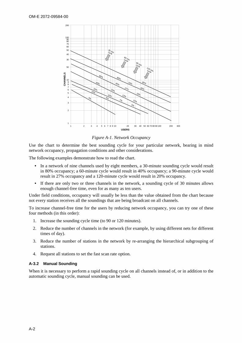
OM-E 2072-09584-00
A-2
80%1098
3
765
4
2
1
200
10090807060
50
40
30
50
1 2 3 4 5 6 7 8 9 10 20 30 40 50 60 70 80 90 300200100
USERS
CH
AN
NEL
S
53%
40%
80%
20%
27%
40%
80%
40%
20%
13%
10%
20%
10%
7%
5%
5%
10%
5%
60 mincycle
30 mincycle
90 mincycle120 mincycle
Figure A-1. Network Occupancy
Use the chart to determine the best sounding cycle for your particular network, bearing in mindnetwork occupancy, propagation conditions and other considerations.
The following examples demonstrate how to read the chart.
In a network of nine channels used by eight members, a 30-minute sounding cycle would resultin 80% occupancy; a 60-minute cycle would result in 40% occupancy; a 90-minute cycle wouldresult in 27% occupancy and a 120-minute cycle would result in 20% occupancy.
If there are only two or three channels in the network, a sounding cycle of 30 minutes allowsenough channel-free time, even for as many as ten users.
Under field conditions, occupancy will usually be less than the value obtained from the chart becausenot every station receives all the soundings that are being broadcast on all channels.
To increase channel-free time for the users by reducing network occupancy, you can try one of thesefour methods (in this order):
1. Increase the sounding cycle time (to 90 or 120 minutes).
2. Reduce the number of channels in the network (for example, by using different nets for differenttimes of day).
3. Reduce the number of stations in the network by re-arranging the hierarchical subgrouping ofstations.
4. Request all stations to set the fast scan rate option.
A-3.2 Manual Sounding
When it is necessary to perform a rapid sounding cycle on all channels instead of, or in addition to theautomatic sounding cycle, manual sounding can be used.

OM-E 2072-09584-00
A-3
A-4. LQA MEMORYThe ALE builds a database of connectivity information based on calls and the ALE soundingmessages transmitted by other stations in the network. This information is stored in a special LQAmemory and is used to determine the link quality of all channels in the networks. The data in the LQAmemory is time-weighted, that is, recent information is given more value than old, thus compensatingfor changing propagation conditions.
A-5. BIDIRECTIONAL HANDSHAKEThe bidirectional handshake is an operator-initiated procedure used to exchange LQA scores withother stations without establishing a link.
NOTE
The Micom-Z can also be programmed to automatically initiate the callto the station after finishing the bidirectional handshake (using theBDLK parameter reached under the ALE programming options).
This procedure is useful in the following cases:
The radio has only recently been switched on and the automatic sounding cycle has not yet beencompleted.
The operator wishes to update the LQA scores before initiating a call to another station, forexample, for example, because of abrupt atmospheric charges, or other propagation changes.
A new or passive station has joined the system.
A bidirectional handshake can be carried out with a single station or with all stations in the net. It canbe carried out either on a single channel, or on all the net channels. When required, a message can alsobe added to the procedure.
After a bidirectional handshake with a single station, the LQA matrices of both radios are updated.The operator can then initiate a call to that station and obtain the best channel automatically.
When the bidirectional handshake procedure is performed with a net, all the stations in the net updatetheir LQA tables.
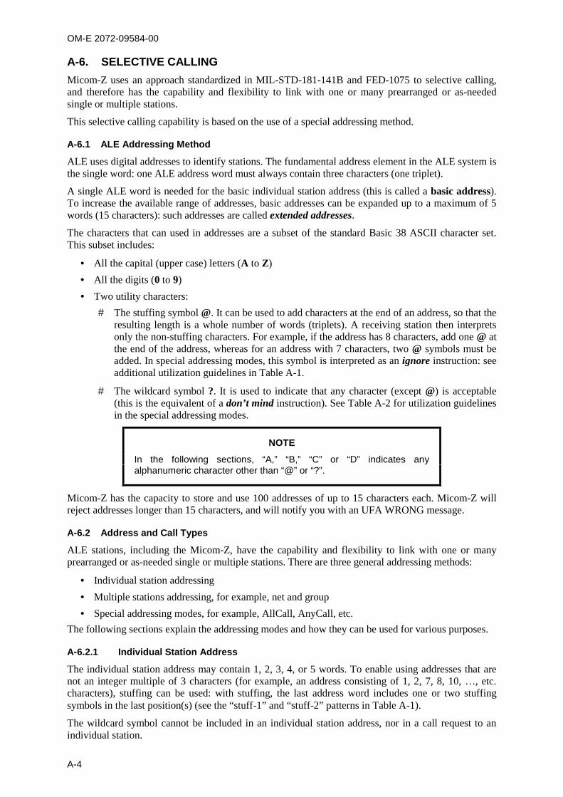
OM-E 2072-09584-00
A-4
A-6. SELECTIVE CALLINGMicom-Z uses an approach standardized in MIL-STD-181-141B and FED-1075 to selective calling,and therefore has the capability and flexibility to link with one or many prearranged or as-neededsingle or multiple stations.
This selective calling capability is based on the use of a special addressing method.
A-6.1 ALE Addressing Method
ALE uses digital addresses to identify stations. The fundamental address element in the ALE system isthe single word: one ALE address word must always contain three characters (one triplet).
A single ALE word is needed for the basic individual station address (this is called a basic address).To increase the available range of addresses, basic addresses can be expanded up to a maximum of 5words (15 characters): such addresses are called extended addresses.
The characters that can used in addresses are a subset of the standard Basic 38 ASCII character set.This subset includes:
All the capital (upper case) letters (A to Z)
All the digits (0 to 9)
Two utility characters:
The stuffing symbol @. It can be used to add characters at the end of an address, so that theresulting length is a whole number of words (triplets). A receiving station then interpretsonly the non-stuffing characters. For example, if the address has 8 characters, add one @ atthe end of the address, whereas for an address with 7 characters, two @ symbols must beadded. In special addressing modes, this symbol is interpreted as an ignore instruction: seeadditional utilization guidelines in Table A-1.
The wildcard symbol ?. It is used to indicate that any character (except @) is acceptable(this is the equivalent of a don’t mind instruction). See Table A-2 for utilization guidelinesin the special addressing modes.
NOTE
In the following sections, “A,” “B,” “C” or “D” indicates anyalphanumeric character other than “@” or “?”.
Micom-Z has the capacity to store and use 100 addresses of up to 15 characters each. Micom-Z willreject addresses longer than 15 characters, and will notify you with an UFA WRONG message.
A-6.2 Address and Call Types
ALE stations, including the Micom-Z, have the capability and flexibility to link with one or manyprearranged or as-needed single or multiple stations. There are three general addressing methods:
Individual station addressing
Multiple stations addressing, for example, net and group
Special addressing modes, for example, AllCall, AnyCall, etc.
The following sections explain the addressing modes and how they can be used for various purposes.
A-6.2.1 Individual Station Address
The individual station address may contain 1, 2, 3, 4, or 5 words. To enable using addresses that arenot an integer multiple of 3 characters (for example, an address consisting of 1, 2, 7, 8, 10, …, etc.characters), stuffing can be used: with stuffing, the last address word includes one or two stuffingsymbols in the last position(s) (see the “stuff-1” and “stuff-2” patterns in Table A-1).
The wildcard symbol cannot be included in an individual station address, nor in a call request to anindividual station.

OM-E 2072-09584-00
A-5
Table A-1. Use of “@” Stuffing Symbol
Pattern Interpretation
A B C “Standard” 3-character address word, shown here for reference. Only the stationwith this address stops scanning and responds
A B @ “Stuff-1” reduced address field, used to add characters “A, B” at the end of theaddress
A @ @ “Stuff-2” reduced address field, used to add character “A” at the end of the address
@ ? @ “AllCall” global address (see also Table A-2): all the stations stop and listen (unlessthis function is inhibited)
@ A @ “Selective AllCall” global address: each station with the same last character “A”stop scanning and listen (unless this function is inhibited
@ @ ? “AnyCall” global address (see also Table A-2): all the stations stop scanning andrespond in randomly selected timeslots (unless this function is inhibited)
@ @ A
@ B@ (option)
“Selective AnyCall” address: each station with same last character(s) “A” (or “B”)stops scanning and responds in a randomly selected timeslot (unless this functionis inhibited), using its own address
@ A B
@ C D (option)
“Double selective AnyCall” address: each station with same last characters “AB” (or“CD”) stops scanning and responds in a randomly selected timeslot (unless thisfunction is inhibited), using its own address
@ @ @ “Null” address; all the stations ignore this address. The null address intended foruse in test and maintenance, or to create an extra “buffer” timeslot
A-6.2.2 Net Addresses
The purpose of a net call is to rapidly and efficiently establish contact with multiple prearranged (net)stations. This is achieved by the use of a single net address.
The net address is actually an additional address assigned in common to all the stations that aremembers of a specific net. Its address structure is identical to that used for individual station addresses(basic or extended, with or without stuffing, as necessary).
When defining a net, each member station is automatically assigned a timeslot: by having each stationanswer a call request in a different timeslot, collisions are avoided.
A-6.2.3 Group Addresses
The purpose of a group call is to rapidly and efficiently establish contact with multiplenon-prearranged (group) stations.
To make a group call, a calling ALE station uses a sequence of the actual individual station addressesof the called stations.
A-6.2.4 Special Addressing Modes – Use of Wildcards
A “wildcard” is a special character,“?”, that a calling station can use to address multiple stations with asingle call address. The following rules apply:
The total length of a calling address that includes wildcard(s) must be equal to that of the calledstation addresses.
A receiving station will accept a wildcard character as a substitute for the alphanumericcharacter in its own address that occupies the same position. This means that the wildcardcharacter is a substitute for any of 36 characters and digits (A to Z, 0 to 9) in the Basic 38character subset.
Multiple wildcard characters can be used in different positions of the same address (basic orextended).
See Table A-2 for examples of patterns using the “?” wildcard symbol.
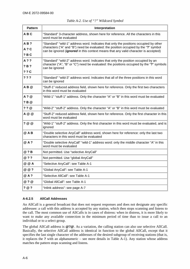
OM-E 2072-09584-00
A-6
Table A-2. Use of “?” Wildcard Symbol
Pattern Interpretation
A B C “Standard” 3-character address, shown here for reference. All the characters in thisword must be evaluated
A B ?
A ? C
? B C
“Standard” “wild-1” address word. Indicates that only the positions occupied by othercharacters (“A” and “B”) need be evaluated: the position occupied by the “?” symbolcan be ignored (ignored in this context means that any valid character is accepted)
A ? ?
? B ?
? ? C
“Standard” “wild-2” address word. Indicates that only the position occupied by ancharacter (“A”, “B” or “C”) need be evaluated: the positions occupied by the “?” symbolscan be ignored
? ? ? “Standard” “wild-3” address word. Indicates that all of the three positions in this wordcan be ignored
A B @ “Stuff-1” reduced address field, shown here for reference. Only the first two charactersin this word must be evaluated
A ? @
? B @
“Wild-1” “stuff-1” address. Only the character “A” or “B” in this word must be evaluated
? ? @ “Wild-2” “stuff-2” address. Only the character “A” or “B” in this word must be evaluated
A @ @ “Stuff-2” reduced address field, shown here for reference. Only the first character in thisword must be evaluated
? @ @ “Wild-1” “stuff-2” address. Only the first character in this word must be evaluated, and isignored
@ A B “Double selective AnyCall” address word, shown here for reference: only the last twocharacters in this word must be evaluated
@ A ? “Double selective AnyCall” “wild-1” address word: only the middle character “A” in thisword must be evaluated
@ ? B Not permitted. Use “selective AnyCall”
@ ? ? Not permitted. Use “global AnyCall”
@ @ A “Selective AnyCall”: see Table A-1
@ @ ? “Global AnyCall”: see Table A-1
@ A ? “Selective AllCall”: see Table A-1
@ ? @ “Global AllCall”: see Table A-1
? @ ? “Inlink address”: see page A-7
A-6.2.5 AllCall Addresses
An AllCall is a general broadcast that does not request responses and does not designate any specificaddressee: a call with this address is accepted by any station, which then stops scanning and listens tothe call. The most common use of AllCalls is in cases of distress: when in distress, it is more likely towant to make any available connection in the minimum period of time than to issue a call to anindividual or to a select group.
The global AllCall address is @?@. As a variation, the calling station can also use selective AllCall.Basically, the selective AllCall address is identical in function to the global AllCall, except that itspecifies the last single character of the addresses of the desired subgroup of receiving stations (that is,it replaces the ? with an alphanumeric – see more details in Table A-1). Any station whose addressmatches the pattern stops scanning and listens.
OM-E 2072-09584-00
A-7
The operator can always initiate an outgoing (transmit) AllCall, but the Micom-Z can be programmedto accept or ignore incoming (receive) AllCalls.
When a radio issues an AllCall, all the stations that are capable of receiving calls receive the AllCall.
In the scan mode, if the Micom-Z station is set to receive AllCalls, it stops scanning when an AllCallis received. If an AllCall channel has been defined, then outgoing AllCalls are performed on thatchannel. If no AllCall channel has been defined, the call is performed on the first scanned channel ofthe net. In the Channel mode, outgoing AllCalls are performed on the currently active channel.
NOTE
You can transmit an AllCall by pressing the ESC button for a fewseconds.
A-6.2.6 AnyCalls
An AnyCall is a general broadcast similar to AllCall with the difference that it requests responses,without designating any specific addressee(s). Therefore, an ALE station may use the AnyCall togenerate responses from essentially unspecified stations, and thus it can identify new stations andconnectivities.
The global AnyCall address is @@?. As a variation, the calling station can also use selective AnyCall,which is identical in function to the global AnyCall, except that it specifies the last single character ofthe addresses of the desired subset of receiving stations (that is, it replaces the ? with an alphanumeric– see more details in Table A-1). If even narrower acceptance and response criteria are required,double selective AnyCall may be used: this is identical to selective AnyCall, except that its specialaddress (@AB) specifies the last two characters that the desired subset of receiving stations.
The operator can always initiate an outgoing (transmit) AnyCall, but the Micom-Z can be programmedto accept or ignore incoming (receive) AnyCalls.
Any station accepting an AnyCall stops scanning, and then initiates a response in a randomly selectedtimeslot.
A-6.2.7 Self Addresses
Stations can also use their own self addresses when making calls. This may be useful for self-test andmaintenance purposes, etc.
The self address may be used only in specifically-addressed calls including a group call, but not in anAllCall or AnyCall.
A-6.2.8 Null Address
The null address is a special type of address that is not directed to, accepted by, or responded to by anystation.
This address is intended for test and maintenance purposes, and to provide buffer time: for example, ifa null address appears in a group call, no station will respond in the associated timeslot.
A-6.2.9 Inlink Address
The inlink address, ?@?, is used to instruct all the stations participating in an already established linkto accept and act upon the information sent with the inlink address. For example, any station can usethe inlink address to send an AMD message that all the linked stations would present to their user.
The inlink address is recognized only after a link is established between two or more stations.

OM-E 2072-09584-00
A-8
A-7. MESSAGESThe ALE enables you to create, send or receive alphanumeric messages (“paging” messages) inaccordance with the AMD (Automatic Display Message) definition in Federal Standard FS-1045.
The messages are displayed on the receiving station LCD display, and can be up to 90 characters long.Messages can be added to any type of call, whether individual, group, net, AllCall, AnyCall,bidirectional handshake, etc. You can create up to 12 messages, and can edit or erase any of themessages at any time.
A-8. USING THE CALLER STACKThe caller stack is an internal memory that stores a list of unanswered calls. Each stack entry containsthe self address of the calling station and a message (AMD) if any was sent. You can view the list,return a call and view any message sent with any call.
The stack can contain up to 10 calls. The radio records an address in the stack only once even if thesame caller makes repeated unanswered calls. However, if the same caller sent calls with differentmessages, all such calls will be saved in the stack. Each stack entry is referred to as a Page.
The appearance of the word STAK next to one of the function buttons of the LCD display indicatesthat there is at least one call in the stack. The STAK indicator is automatically turned off when allpages in the stack have been erased.
The stack is arranged in FIFO order, that is, the first address that enters the stack is also the first thatyou see on the display. If the stack is full and a new call is received, the oldest call in the stack isautomatically erased.
For convenience, addresses appearing in the stack can be easily added to the ALE address directory.
A-9. QUICK CALLDuring a call, the radio saves the latest destination information as the quick call information. Whenthe user presses the PTT of the microphone or handset twice in rapid sequence, the radio automaticallydirects the call to that address.
In the ALE mode, channel information is also retained and used for quick calls.

OM-E 2072-09584-00
B-1
APPENDIX B
CONNECTOR DATA
B-1. MICOM-Z TRANSCEIVER CONNECTORS
B-1.1 Microphone Connector
The microphone connector is located on the radio front panel. Table B-1 lists the functions of themicrophone connector pins.
Table B-1. Microphone Connector, Pin Functions
Pin Designation Description
1 SWA+ Power output to the microphone
2 RXD Serial communication line (input)
3 TXD Serial communication line (output)
4 GND Ground line
5 MIC AUDIO Input audio signals generated by the microphone (600 impedance; 300 mV tone is required for full output power).
6 PTT MIC Activates transmission by short to ground.
7 MONITOR Mutes the speaker before transmission is enabled (shortmomentary to ground to open speaker).
8 AUDIO OUT Receive audio output to earphone (600 , 300 mVRMS)
B-1.2 Antenna Connector
The N type antenna connector is located on the rear panel of the transceiver. In the transmit mode, it isused to feed the antenna with the transmit signal; in the receive mode, it is used to connect thereceived signal from the antenna to the radio.
B-1.3 ACCESSORY Connector
The ACCESSORY connector is a 44-pin D-type male connector located on the radio rear panel. It isintended for use with external accessories such as modems, PCs, etc., or for connection to the coolingtray (para. B-2.4). Table B-2 lists the pin functions of the ACCESSORY connector.
Table B-2. ACCESSORY Connector, Pin Functions
Pin Designation Description
1 SPKR- Differential output to external 8, 5W speaker
2 STOP SCAN Digital control input for stop scan function (optional function)
3 SPKR+ Differential output to external 8, 5W speaker
4 EXT RX AUDIO+ Differential received audio output (0 dBm/600; not controlled byvolume)5 EXT RX AUDIO-
6 EXT TX AUDIO+ Differential transmit audio input (600 input impedance, 0 dBm isrequired for full power)7 EXT TX AUDIO-
8 PTT IN VOICE Transmission command (short to ground) for voice signals
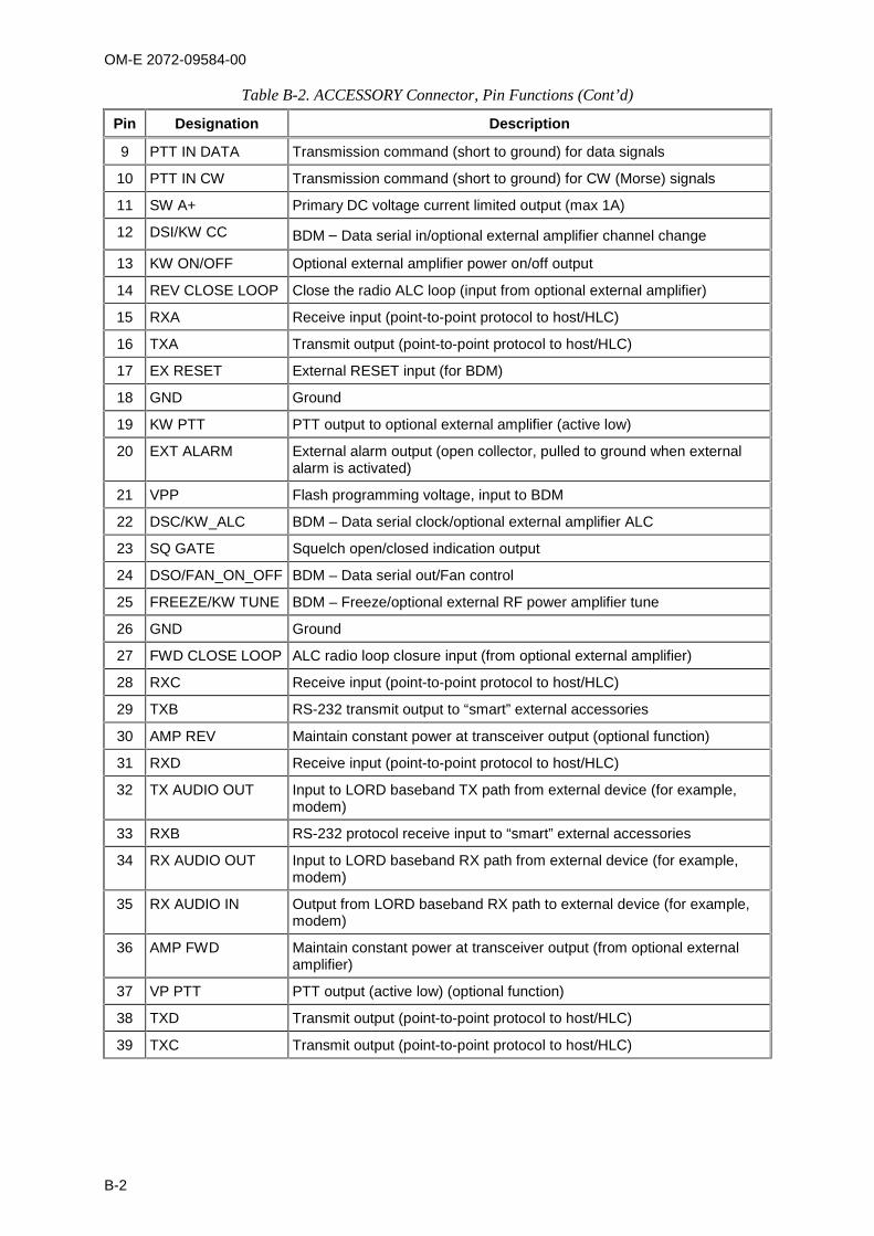
OM-E 2072-09584-00
B-2
Table B-2. ACCESSORY Connector, Pin Functions (Cont’d)
Pin Designation Description
9 PTT IN DATA Transmission command (short to ground) for data signals
10 PTT IN CW Transmission command (short to ground) for CW (Morse) signals
11 SW A+ Primary DC voltage current limited output (max 1A)
12 DSI/KW CC BDM – Data serial in/optional external amplifier channel change
13 KW ON/OFF Optional external amplifier power on/off output
14 REV CLOSE LOOP Close the radio ALC loop (input from optional external amplifier)
15 RXA Receive input (point-to-point protocol to host/HLC)
16 TXA Transmit output (point-to-point protocol to host/HLC)
17 EX RESET External RESET input (for BDM)
18 GND Ground
19 KW PTT PTT output to optional external amplifier (active low)
20 EXT ALARM External alarm output (open collector, pulled to ground when externalalarm is activated)
21 VPP Flash programming voltage, input to BDM
22 DSC/KW_ALC BDM – Data serial clock/optional external amplifier ALC
23 SQ GATE Squelch open/closed indication output
24 DSO/FAN_ON_OFF BDM – Data serial out/Fan control
25 FREEZE/KW TUNE BDM – Freeze/optional external RF power amplifier tune
26 GND Ground
27 FWD CLOSE LOOP ALC radio loop closure input (from optional external amplifier)
28 RXC Receive input (point-to-point protocol to host/HLC)
29 TXB RS-232 transmit output to “smart” external accessories
30 AMP REV Maintain constant power at transceiver output (optional function)
31 RXD Receive input (point-to-point protocol to host/HLC)
32 TX AUDIO OUT Input to LORD baseband TX path from external device (for example,modem)
33 RXB RS-232 protocol receive input to “smart” external accessories
34 RX AUDIO OUT Input to LORD baseband RX path from external device (for example,modem)
35 RX AUDIO IN Output from LORD baseband RX path to external device (for example,modem)
36 AMP FWD Maintain constant power at transceiver output (from optional externalamplifier)
37 VP PTT PTT output (active low) (optional function)
38 TXD Transmit output (point-to-point protocol to host/HLC)
39 TXC Transmit output (point-to-point protocol to host/HLC)

OM-E 2072-09584-00
B-3
Table B-2. ACCESSORY Connector, Pin Functions (Cont’d)
Pin Designation Description
40 TX AUDIO IN Output from LORD baseband TX path to external device (for example,modem)
41 EXT RX AUDIO(2)+Audio output from the optional ISB processor (secondary sideband)
42 EXT TX AUDIO(2)-
43 EXT RX DATA-Baseband output (0 dBm, 600 ), unsquelched
44 EXT RX DATA+
B-1.4 VDC IN Power Connector
The VDC IN power connector located on the rear panel of the radio is used to provide power to theradio. Table B-3 lists the functions of the VDC IN connector pins.
Table B-3. VDC IN Power Connector, Pin Functions
Pin Designation Description
1 Power Positive input line
2 Ground Return (negative) line
B-2. COOLING TRAY CONNECTORS
B-2.1 44-Pin/25-Pin Adapter Cable
The 44-pin/25-pin adapter cable is used to connect the 25-pin TO RADIO connector of the coolingtray to the 44-pin ACCESSORY connector of Micom-Z. Table B-4 lists the cable wiring diagram.
Table B-4. 44-Pin/25-Pin Adapter Cable Wiring Diagram
44-PinConnector
25-PinConnector
44-PinConnector
25-PinConnector
1 1 43 14
44 2 15 15
3 3 16 16
4 4 17 17
5 5 18 18
6 6 19 19
7 7 20 20
8 8 21 21
9 9 22 22
10 10 23 23
11 11 24 24
12 12 25 25
13 13
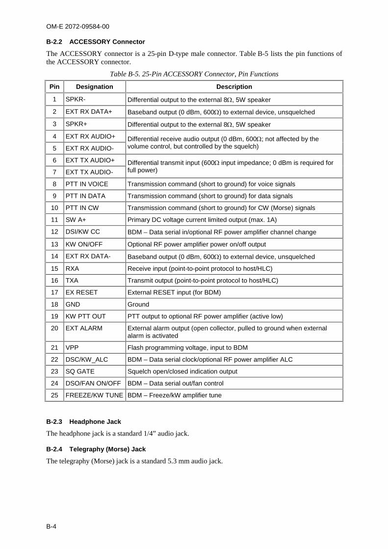
OM-E 2072-09584-00
B-4
B-2.2 ACCESSORY Connector
The ACCESSORY connector is a 25-pin D-type male connector. Table B-5 lists the pin functions ofthe ACCESSORY connector.
Table B-5. 25-Pin ACCESSORY Connector, Pin Functions
Pin Designation Description
1 SPKR- Differential output to the external 8, 5W speaker
2 EXT RX DATA+ Baseband output (0 dBm, 600) to external device, unsquelched
3 SPKR+ Differential output to the external 8, 5W speaker
4 EXT RX AUDIO+ Differential receive audio output (0 dBm, 600; not affected by thevolume control, but controlled by the squelch)5 EXT RX AUDIO-
6 EXT TX AUDIO+ Differential transmit input (600 input impedance; 0 dBm is required forfull power)7 EXT TX AUDIO-
8 PTT IN VOICE Transmission command (short to ground) for voice signals
9 PTT IN DATA Transmission command (short to ground) for data signals
10 PTT IN CW Transmission command (short to ground) for CW (Morse) signals
11 SW A+ Primary DC voltage current limited output (max. 1A)
12 DSI/KW CC BDM – Data serial in/optional RF power amplifier channel change
13 KW ON/OFF Optional RF power amplifier power on/off output
14 EXT RX DATA- Baseband output (0 dBm, 600) to external device, unsquelched
15 RXA Receive input (point-to-point protocol to host/HLC)
16 TXA Transmit output (point-to-point protocol to host/HLC)
17 EX RESET External RESET input (for BDM)
18 GND Ground
19 KW PTT OUT PTT output to optional RF power amplifier (active low)
20 EXT ALARM External alarm output (open collector, pulled to ground when externalalarm is activated
21 VPP Flash programming voltage, input to BDM
22 DSC/KW_ALC BDM – Data serial clock/optional RF power amplifier ALC
23 SQ GATE Squelch open/closed indication output
24 DSO/FAN ON/OFF BDM – Data serial out/fan control
25 FREEZE/KW TUNE BDM – Freeze/kW amplifier tune
B-2.3 Headphone Jack
The headphone jack is a standard 1/4” audio jack.
B-2.4 Telegraphy (Morse) Jack
The telegraphy (Morse) jack is a standard 5.3 mm audio jack.
OM-E 2072-09584-00
C-1
APPENDIX C
OVER-THE-AIR REMOTE DISABLE FUNCTION
C-1. SCOPEThis Appendix covers the over-the-air remote disable capability of Micom-Z HF-SSB transceiversoperating in the ALE or CCIR modes.
C-2. OVERVIEWWhen a radio set is lost or stolen, it is necessary to prevent unauthorized use. Among other undesirablepossibilities, unauthorized use may reveal sensitive information, for example, frequencies and callsigns.
Micom-Z is designed to prevent unauthorized use: an authorized operator can transmit a command toanother radio set to effectively disable it, by erasing its operational parameters. This returns the radioset to the unprogrammed state (after receiving the command, the radio continuously displays NOTPROG). Therefore, to return the radio to a usable state, it must be programmed by means of theMicom Radio Control Application (MRC).
The over-the-air remote disable command is transmitted as an AMD message directed to the targetradio, using the paging function. Therefore, for this remote disable capability to be available, the targetradio must operate in the ALE or CCIR mode.
The command string can be individually programmed on each radio set. The factory-default string isKILL BILL, and it can be changed using the MRC (version 2.21 or higher). Make sure to change thisdefault with a reasonably secure string (the maximum string length is 30 characters).
C-3. OPERATING INSTRUCTIONSTo send an over-the-air remote disable command:
1. Obtain the parameters needed to establish ALE or CCIR communication with the target radioset (for example, address and ALE net parameters, or CCIR frequency table).
2. Prepare the AMD message with the prescribed command string (for example, KILL BILL), tobe sent.
3. Call the target radio, attaching the AMD message using the PAGE function.
NOTE
When the target radio receives the call request, it automaticallyrestarts and starts displaying NOT PROG. Therefore, do not expect aconfirmation for the disable command.
C-4. RESTORING THE RADIO TO NORMAL OPERATIONTo return a radio set to normal operation, it is necessary to connect it to a PC running the MRC andprogram it with the appropriate parameters.
For detailed instructions, refer to the Micom Radio Control Application User’s Guide, PublicationOM-E 2072-09602-10.

OM-E 2072-09584-00
C-2
Intentionally Left Blank