MiCOM P591, P592, P593 - My Protection Guide the MMLG, MMLB and MiCOM P990 types, hazardous voltages...
90
MiCOM P591, P592, P593 Technical Manual Communication Interface Units for Optical/Electrical Signal Conversion Platform Hardware Version: B Publication Reference: P59x/EN M/B11 P59x/EN M/B11 © 2011. ALSTOM, the ALSTOM logo and any alternative version thereof are trademarks and service marks of ALSTOM. The other names mentioned, registered or not, are the property of their respective companies. The technical and other data contained in this document is provided for information only. Neither ALSTOM, its officers or employees accept responsibility for, or should be taken as making any representation or warranty (whether express or implied), as to the accuracy or completeness of such data or the achievement of any projected performance criteria where these are indicated. ALSTOM reserves the right to revise or change this data at any time without further notice. GRID
Transcript of MiCOM P591, P592, P593 - My Protection Guide the MMLG, MMLB and MiCOM P990 types, hazardous voltages...

MiCOM P591, P592, P593
Technical Manual
Communication Interface Units for
Optical/Electrical Signal Conversion
Platform Hardware Version: B
Publication Reference: P59x/EN M/B11
P59x/EN M/B11 © 2011. ALSTOM, the ALSTOM logo and any alternative version thereof are trademarks and service marks of ALSTOM. The other names
mentioned, registered or not, are the property of their respective companies. The technical and other data contained in this document is provided for information only.
Neither ALSTOM, its officers or employees accept responsibility for, or should be taken as making any representation or warranty (whether express or implied), as to
the accuracy or completeness of such data or the achievement of any projected performance criteria where these are indicated. ALSTOM reserves the right to revise or
change this data at any time without further notice.
GRID

CONTENTS
SS Safety Section P59x/EN SS/H11
Chapter 1 Introduction P59x/EN IT/B11
Chapter 2 Technical Data P59x/EN TD/B11
Chapter 3 Operation P59x/EN OP/B11
Chapter 4 Commissioning P59x/EN CM/B11
Chapter 5 Troubleshooting P59x/EN TS/B11
Chapter 6 Installation P59x/EN IN/B11
IT
TD
OP
CM
TS
IN


Safety Section P59x/EN SS/H11
SS
SAFETY SECTION

P59x/EN SS/H11 Safety Section
SS
Safety Section P59x/EN SS/H11
(SS) - 1
SS
CONTENTS
1. INTRODUCTION 3
2. HEALTH AND SAFETY 3
3. SYMBOLS AND LABELS ON THE EQUIPMENT 4
3.1 Symbols 4
3.2 Labels 4
4. INSTALLING, COMMISSIONING AND SERVICING 4
5. DE-COMMISSIONING AND DISPOSAL 7
6. TECHNICAL SPECIFICATIONS FOR SAFETY 8
6.1 Protective fuse rating 8
6.2 Protective class 8
6.3 Installation category 8
6.4 Environment 8

P59x/EN SS/H11 Safety Section (SS) - 2
SS
Safety Section P59x/EN SS/H11
(SS) - 3
STANDARD SAFETY STATEMENTS AND EXTERNAL LABEL INFORMATION FOR ALSTOM GRID EQUIPMENT
1. INTRODUCTION
This Safety Section and the relevant equipment documentation provide full information on safe handling, commissioning and testing of this equipment. This Safety Section also includes reference to typical equipment label markings.
The technical data in this Safety Section is typical only, see the technical data section of the relevant equipment documentation for data specific to a particular equipment.
SS
Before carrying out any work on the equipment the user should be familiar with the contents of this Safety Section and the ratings on the equipment’s rating label.
Reference should be made to the external connection diagram before the equipment is installed, commissioned or serviced.
Language specific, self-adhesive User Interface labels are provided in a bag for some equipment.
2. HEALTH AND SAFETY
The information in the Safety Section of the equipment documentation is intended to ensure that equipment is properly installed and handled in order to maintain it in a safe condition.
It is assumed that everyone who will be associated with the equipment will be familiar with the contents of this Safety Section, or the Safety Guide (SFTY/4L M).
When electrical equipment is in operation, dangerous voltages will be present in certain parts of the equipment. Failure to observe warning notices, incorrect use, or improper use may endanger personnel and equipment and also cause personal injury or physical damage.
Before working in the terminal strip area, the equipment must be isolated.
Proper and safe operation of the equipment depends on appropriate shipping and handling, proper storage, installation and commissioning, and on careful operation, maintenance and servicing. For this reason only qualified personnel may work on or operate the equipment.
Qualified personnel are individuals who:
Are familiar with the installation, commissioning, and operation of the equipment and of the system to which it is being connected;
Are able to safely perform switching operations in accordance with accepted safety engineering practices and are authorized to energize and de-energize equipment and to isolate, ground, and label it;
Are trained in the care and use of safety apparatus in accordance with safety engineering practices;
Are trained in emergency procedures (first aid).
The equipment documentation gives instructions for its installation, commissioning, and operation. However, the manuals cannot cover all conceivable circumstances or include detailed information on all topics. In the event of questions or specific problems, do not take any action without proper authorization. Contact the appropriate Alstom Grid technical sales office and request the necessary information.
P59x/EN SS/H11 Safety Section (SS) - 4
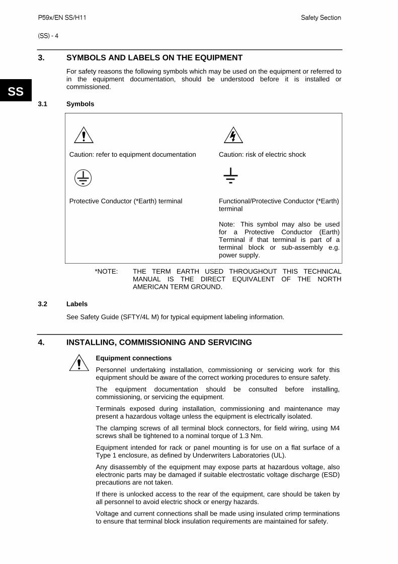
3. SYMBOLS AND LABELS ON THE EQUIPMENT
For safety reasons the following symbols which may be used on the equipment or referred to in the equipment documentation, should be understood before it is installed or commissioned. SS
3.1 Symbols
Caution: refer to equipment documentation
Caution: risk of electric shock
Protective Conductor (*Earth) terminal
Functional/Protective Conductor (*Earth) terminal
Note: This symbol may also be used for a Protective Conductor (Earth) Terminal if that terminal is part of a terminal block or sub-assembly e.g. power supply.
*NOTE: THE TERM EARTH USED THROUGHOUT THIS TECHNICAL MANUAL IS THE DIRECT EQUIVALENT OF THE NORTH AMERICAN TERM GROUND.
3.2 Labels
See Safety Guide (SFTY/4L M) for typical equipment labeling information.
4. INSTALLING, COMMISSIONING AND SERVICING
Equipment connections
Personnel undertaking installation, commissioning or servicing work for this equipment should be aware of the correct working procedures to ensure safety.
The equipment documentation should be consulted before installing, commissioning, or servicing the equipment.
Terminals exposed during installation, commissioning and maintenance may present a hazardous voltage unless the equipment is electrically isolated.
The clamping screws of all terminal block connectors, for field wiring, using M4 screws shall be tightened to a nominal torque of 1.3 Nm.
Equipment intended for rack or panel mounting is for use on a flat surface of a Type 1 enclosure, as defined by Underwriters Laboratories (UL).
Any disassembly of the equipment may expose parts at hazardous voltage, also electronic parts may be damaged if suitable electrostatic voltage discharge (ESD) precautions are not taken.
If there is unlocked access to the rear of the equipment, care should be taken by all personnel to avoid electric shock or energy hazards.
Voltage and current connections shall be made using insulated crimp terminations to ensure that terminal block insulation requirements are maintained for safety.

Safety Section P59x/EN SS/H11
(SS) - 5
Watchdog (self-monitoring) contacts are provided in numerical relays to indicate the health of the device. Alstom Grid strongly recommends that these contacts are hardwired into the substation's automation system, for alarm purposes.
To ensure that wires are correctly terminated the correct crimp terminal and tool for the wire size should be used.
The equipment must be connected in accordance with the appropriate connection diagram.
Protection Class I Equipment
- Before energizing the equipment it must be earthed using the protective conductor terminal, if provided, or the appropriate termination of the supply plug in the case of plug connected equipment.
- The protective conductor (earth) connection must not be removed since the protection against electric shock provided by the equipment would be lost.
- When the protective (earth) conductor terminal (PCT) is also used to terminate cable screens, etc., it is essential that the integrity of the protective (earth) conductor is checked after the addition or removal of such functional earth connections. For M4 stud PCTs the integrity of the protective (earth) connections should be ensured by use of a locknut or similar.
The recommended minimum protective conductor (earth) wire size is 2.5 mm² (3.3 mm² for North America) unless otherwise stated in the technical data section of the equipment documentation, or otherwise required by local or country wiring regulations.
The protective conductor (earth) connection must be low-inductance and as short as possible.
All connections to the equipment must have a defined potential. Connections that are pre-wired, but not used, should preferably be grounded when binary inputs and output relays are isolated. When binary inputs and output relays are connected to common potential, the pre-wired but unused connections should be connected to the common potential of the grouped connections.
Before energizing the equipment, the following should be checked:
- Voltage rating/polarity (rating label/equipment documentation);
- CT circuit rating (rating label) and integrity of connections;
- Protective fuse rating;
- Integrity of the protective conductor (earth) connection (where applicable);
- Voltage and current rating of external wiring, applicable to the application.
Accidental touching of exposed terminals
If working in an area of restricted space, such as a cubicle, where there is a risk of electric shock due to accidental touching of terminals which do not comply with IP20 rating, then a suitable protective barrier should be provided.
Equipment use
If the equipment is used in a manner not specified by the manufacturer, the protection provided by the equipment may be impaired.
Removal of the equipment front panel/cover
Removal of the equipment front panel/cover may expose hazardous live parts, which must not be touched until the electrical power is removed.
SS

P59x/EN SS/H11 Safety Section (SS) - 6
UL and CSA/CUL listed or recognized equipment
To maintain UL and CSA/CUL Listing/Recognized status for North America the equipment should be installed using UL or CSA Listed or Recognized parts for the following items: connection cables, protective fuses/fuseholders or circuit breakers, insulation crimp terminals and replacement internal battery, as specified in the equipment documentation.
For external protective fuses a UL or CSA Listed fuse shall be used. The Listed type shall be a Class J time delay fuse, with a maximum current rating of 15 A and a minimum d.c. rating of 250 Vd.c., for example type AJT15.
Where UL or CSA Listing of the equipment is not required, a high rupture capacity (HRC) fuse type with a maximum current rating of 16 Amps and a minimum d.c. rating of 250 Vd.c. may be used, for example Red Spot type NIT or TIA.
Equipment operating conditions
The equipment should be operated within the specified electrical and environmental limits.
Current transformer circuits
Do not open the secondary circuit of a live CT since the high voltage produced may be lethal to personnel and could damage insulation. Generally, for safety, the secondary of the line CT must be shorted before opening any connections to it.
For most equipment with ring-terminal connections, the threaded terminal block for current transformer termination has automatic CT shorting on removal of the module. Therefore external shorting of the CTs may not be required, the equipment documentation should be checked to see if this applies.
For equipment with pin-terminal connections, the threaded terminal block for current transformer termination does NOT have automatic CT shorting on removal of the module.
External resistors, including voltage dependent resistors (VDRs)
Where external resistors, including voltage dependent resistors (VDRs), are fitted to the equipment, these may present a risk of electric shock or burns, if touched.
Battery replacement
Where internal batteries are fitted they should be replaced with the recommended type and be installed with the correct polarity to avoid possible damage to the equipment, buildings and persons.
Insulation and dielectric strength testing
Insulation testing may leave capacitors charged up to a hazardous voltage. At the end of each part of the test, the voltage should be gradually reduced to zero, to discharge capacitors, before the test leads are disconnected.
Insertion of modules and pcb cards
Modules and PCB cards must not be inserted into or withdrawn from the equipment whilst it is energized, since this may result in damage.
Insertion and withdrawal of extender cards
Extender cards are available for some equipment. If an extender card is used, this should not be inserted or withdrawn from the equipment whilst it is energized. This is to avoid possible shock or damage hazards. Hazardous live voltages may be accessible on the extender card.
SS
Safety Section P59x/EN SS/H11
(SS) - 7
External test blocks and test plugs
Great care should be taken when using external test blocks and test plugs such as the MMLG, MMLB and MiCOM P990 types, hazardous voltages may be accessible when using these. *CT shorting links must be in place before the insertion or removal of MMLB test plugs, to avoid potentially lethal voltages.
*Note: When a MiCOM P992 Test Plug is inserted into the MiCOM P991 Test Block, the secondaries of the line CTs are automatically shorted, making them safe.
Fiber optic communication
Where fiber optic communication devices are fitted, these should not be viewed directly. Optical power meters should be used to determine the operation or signal level of the device.
Cleaning
The equipment may be cleaned using a lint free cloth dampened with clean water, when no connections are energized. Contact fingers of test plugs are normally protected by petroleum jelly, which should not be removed.
SS
5. DE-COMMISSIONING AND DISPOSAL
De-commissioning
The supply input (auxiliary) for the equipment may include capacitors across the supply or to earth. To avoid electric shock or energy hazards, after completely isolating the supplies to the equipment (both poles of any dc supply), the capacitors should be safely discharged via the external terminals prior to de-commissioning.
Disposal
It is recommended that incineration and disposal to water courses is avoided. The equipment should be disposed of in a safe manner. Any equipment containing batteries should have them removed before disposal, taking precautions to avoid short circuits. Particular regulations within the country of operation, may apply to the disposal of the equipment.
P59x/EN SS/H11 Safety Section (SS) - 8
6. TECHNICAL SPECIFICATIONS FOR SAFETY
Unless otherwise stated in the equipment technical manual, the following data is applicable.
SS 6.1 Protective fuse rating
The recommended maximum rating of the external protective fuse for equipments is 16A, high rupture capacity (HRC) Red Spot type NIT, or TIA, or equivalent. The protective fuse should be located as close to the unit as possible.
DANGER - CTs must NOT be fused since open circuiting them may produce lethal hazardous voltages.
6.2 Protective class
IEC 60255-27: 2005 Class I (unless otherwise specified in the equipment documentation).
EN 60255-27: 2005 This equipment requires a protective conductor (earth) connection to ensure user safety.
6.3 Installation category
IEC 60255-27: 2005 Installation category III (Overvoltage Category III):
EN 60255-27: 2005 Distribution level, fixed installation.
Equipment in this category is qualification tested at 5 kV peak, 1.2/50 µs, 500 , 0.5 J, between all supply circuits and earth and also between independent circuits.
6.4 Environment
The equipment is intended for indoor installation and use only. If it is required for use in an outdoor environment then it must be mounted in a specific cabinet of housing which will enable it to meet the requirements of IEC 60529 with the classification of degree of protection IP54 (dust and splashing water protected).
Pollution Degree - Pollution Degree 2 Compliance is demonstrated by reference to safety Altitude - Operation up to 2000m standards.
IEC 60255-27:2005
EN 60255-27: 2005

Introduction P59x/EN IT/B11 MiCOM P591, P592, P593
(IT) 1-1
IT
INTRODUCTION
Date: 9th October 2009
Hardware Suffix: B
Software Version:
Connection Diagrams: 10P59x02 x = 1 to 3

P59x/EN IT/B11 Introduction (IT) 1-2
MiCOM P591, P592, P593
IT

Introduction P59x/EN IT/B11 MiCOM P591, P592, P593
(IT) 1-3
IT
CONTENTS
1 MICOM P59X DOCUMENTATION STRUCTURE 5
2 INTRODUCTION TO MICOM 6
3 PRODUCT SCOPE 7
4 ORDERING OPTIONS 8
FIGURES
Figure 1: P591, P592, P593 Application overview 7
TABLES
Table 1: P591, P592, P593 Cortec 8

P59x/EN IT/B11 Introduction (IT) 1-4
MiCOM P591, P592, P593
IT

Introduction P59x/EN IT/B11 MiCOM P591, P592, P593
(IT) 1-5
IT
1 MICOM P59X DOCUMENTATION STRUCTURE
This manual provides a functional and technical description of the MiCOM P591, P592 and P593 interface units, and a comprehensive set of instructions for the units’ use and application.
The chapter contents are summarized as follows.
P59x/EN IT Introduction P591, P592, P593
A guide to the MiCOM range of equipment and the documentation structure. General safety aspects of handling Electronic Equipment are discussed with particular reference to safety symbols. Also a general functional overview of the unit and brief application summary is given.
P59x/EN TD Technical Data
Technical data including setting ranges, accuracy limits, recommended operating conditions, ratings and performance data. Compliance with norms and international standards is quoted where appropriate.
P59x/EN OP Operation
A comprehensive and detailed functional description of the unit’s functionality.
P59x/EN CM Commissioning
Instructions on how to commission the unit, including checks on the functionality of the unit.
P59x/EN TS Troubleshooting
Advice on how to recognize failure modes and the recommended course of action. Includes guidance on whom in ALSTOM Grid to contact for advice.
P59x/EN IN Installation
Recommendations on unpacking, handling, inspection and storage of the unit. A guide to the mechanical and electrical installation of the unit is provided, incorporating grounding (earthing) recommendations. All external wiring connections to the unit are shown.

P59x/EN IT/B11 Introduction (IT) 1-6
MiCOM P591, P592, P593
IT
2 INTRODUCTION TO MiCOM
MiCOM is a comprehensive solution capable of meeting all electricity supply requirements. It comprises a range of components, systems and services from ALSTOM Grid.
Central to the MiCOM concept is flexibility.
MiCOM allows you to define an application solution and integrate it with your power supply control system with extensive communication capabilities.
The components within the MiCOM range are:
P range protection relays;
C range control products;
M range measurement products for accurate metering and monitoring;
S range versatile PC support and substation control packages.
MiCOM products include extensive facilities for recording information on the state and behavior of the power system using disturbance and fault records. At regular intervals they can provide measurements of the system to a control center, allowing remote monitoring and control.
For up-to-date information on any MiCOM product, visit our website:
www.alstom.com/grid/sas

Introduction P59x/EN IT/B11 MiCOM P591, P592, P593
(IT) 1-7
3 PRODUCT SCOPE
The MiCOM P591, P592 and P593 are stand-alone fiber optic to electrical communications interface units. They can be used with the MiCOM P54x and P521 current differential relays or other MiCOM protection relays that support InterMiCOM64 communications.
The P591, P592 and P593 interface units allow the relays to be connected to remote multiplexing equipment or other communication network equipment.
The MiCOM P591conforms to the ITU-T G.703 co-directional interface at up to 64 kbit/s.
The MiCOM P592 conforms to the ITU-T V.35 interface at up to 64 kbit/s.
The MiCOM P593 conforms to the ITU-T X.21 interface at up to 64 kbit/s.
The interface units are usually located close to the PCM multiplexer and provide signal conversion between the relay and the PCM multiplexer. The interface units are housed in a MiCOM 10TE case and are suitable for flush mounting. The communication connections of the devices are shown in Figure 1.
P591 interface unit
P593 interface unit
Multiplexer Multiplexer or xDSL modem
Multiplexer Multiplexer or xDSL modem
P591 interface unit
P593 interface unit
P592 interface unit
Multiplexer or xDSL modem
Multiplexer or xDSL modem
P592 interface unit
G.703 V.35 X.21
G.703 V.35 X.21
850 nm multimode optical fiber
850 nm multimode optical fiber
850 nm multimode optical fiber
850 nm multimode optical
fiber
850 nm multimode optical
fiber
850 nm multimode optical
fiber
P4416ENb
Figure 1: P591, P592, P593 Application overview
IT

P59x/EN IT/B11 Introduction (IT) 1-8
MiCOM P591, P592, P593
IT
4 ORDERING OPTIONS
Information Required with Order Information required with order:
P591, P592, P593 CORTEC
Variants Order Number
P59_ Differential Current Communications Interface 1 - 3 4 5 6 7 8 9
10
11
12
13
14
15
(for use with MICOM Current Differential Relays) P59
G.703 Interface 1
V.35 Interface 2
X.21 Interface 3
Vx Auxiliary Rating
19.5 - 300 Vdc 6
Inom = Not Applicable 0
Hardware Options
64 kbps 1
Product Specific = NONE A
Protocol Options = Not Applicable 0
Mounting
Flush Rack / Panel M
Language:
Multilingual
(Internationally Recognised Symbols) 0
Software
Standard - (Not Applicable) 0 0
Setting Files
Standard - (Not Applicable) 0
Design Suffix
Factory Defined *
Optional Extras
Table 1: P591, P592, P593 Cortec
Technical Data P59x/EN TD/B11 MiCOM P591, P592, P593
(TD) 2-1
TD
TECHNICAL DATA
Date: 9th October 2009
Hardware Suffix: B
Software Version:
Connection Diagrams: 10P59x02 x = 1 to 3

P59x/EN TD/B11 Technical Data (TD) 2-2
MiCOM P591, P592, P593
TD

Technical Data P59x/EN TD/B11 MiCOM P591, P592, P593
(TD) 2-3
TD
Mechanical specifications
Design
Modular MiCOM, 10TE case. Mounting is front of panel Flush / Rack mounting
Enclosure protection
Per EN 60529: 1992: IP 52 Protection (front panel) against dust and dripping water, IP 50 Protection for sides of the case, IP 20 Protection for the rear.
Weight
1.5 kg
Terminals
General input/output terminals
P591 Power and G.703 connectors (green blocks) on the rear. P592 Power (green blocks) and V.35 (25-way connector) on the rear. P593 Power (green blocks) and X.21 (25-way connector) on the rear.
Case protective earth connection
Ground tag, M4 hole. Must be earthed (grounded) for safety, minimum earth wire size 2.5 mm2.
Optical interface
BFOC 2.5 -(ST®)-interface for glass fiber, as per EN 874-10. 820 nm short-haul fibers, one Tx and one Rx. Operating distance: <2 km. Typical Tx output level: -14 dBm (launched into 1 m of 50/125 µm fiber at 25°C ambient temp). Transmitter type: LED Maximum Rx level: -10 dBm Receiver type: Photodetector PIN diode Rx sensitivity: -18 to -32 dBm Optical budget 0 to 8 dBm
Ratings
Burden: 4.5 W
Power supply
Auxiliary voltage (Vx dc) Nominal supply rating: 24 V to 250 V Operating range: 19.5 V to 300 V Power supply interruption: per IEC 0255-11: 1979 The interface units will withstand 200 ms interruption in the dc auxiliary supply, without de-energizing.
Environmental conditions
Ambient temperature range
Per EN 60068-2-1:2007 and EN 60068-2-2:2007: Operating temperature range: -25°C to +55°C (or -13°F to +131°F) Storage and transit: -25°C to +70°C (or -13°F to +158°F) Per EN 60068-2-14:2000 5 cycles, -25°C to +55°C, 1°C/min rate of change
Ambient humidity range
Per EN 60068-2-78: 2002: 56 days at 93% relative humidity and +40 °C
Type tests
Insulation
Per EN 60255-27: 2005 Insulation resistance > 100 M at 500 Vdc
(Using only electronic / brushless insulation tester).
Creepage distances and clearances
EN 60255-27: 2005 Pollution degree 3, Overvoltage category III, Impulse test voltage 5 kV.
High voltage (dielectric) withstand
Per EN 60255-27: 2005, 2 kV rms AC, 1 minute: Between all independent circuits. Between independent circuits and protective (earth) conductor terminal.
Impulse voltage withstand test
Per EN 60255-27: 2005 Front time: 1.2 µs, Time to half-value: 50 µs, Peak value: 5 kV, 0.5 J Between all independent circuits. Between all independent circuits and protective (earth) conductor terminal. Between the terminals of independent circuits.
Electromagnetic compatibility (EMC)
1 MHz burst high frequency disturbance test
Per EN 60255-22-1: 2008, Class III, Common-mode test voltage: 2.5 kV, Differential test voltage: 1.0 kV, Test duration: 2 s, Source impedance: 200 EIA(RS)232 ports excepted.
100 kHz / 1 MHz damped oscillatory test
Per EN61000-4-18: 2007: Level 3 Common mode test voltage: 2.5 kV Differential mode test voltage: 1 kV
P59x/EN TD/B11 Technical Data (TD) 2-4
MiCOM P591, P592, P593
Immunity to electrostatic discharge
TD
s s
l 3,
unity
ly,
Per EN
Hz/1 MHz with a burst duration of
66 dBVV (quasi peak)
).
03 Class A.
ndards blish conformity:
ow
establish conformity: 05
Per EN 60255-22-2: 1997, Class IV or EN 61000-4-2: 1995, Class IV, 15 kV discharge in air to user interface, display, communication port and exposed metalwork. 8 kV point contact discharge to any part of the front of the product.
Electrical fast transient or burst requirements
Per EN 60255-22-4: 2002, Class A and EN61000-4-4:2004. Test severity Class IV: Amplitude: 2 kV, burst frequency 5 kHz (Class IV) Applied to communications port. Amplitude: 4 kV, burst frequency 2.5 kHz (Class IV). Applied directly to auxiliary supply and communications port. Amplitude: 4 kV, burst frequency 5 kHz (Class IV) applied directly to auxiliary supply.
Surge withstand capability
Per IEEE/ANSI C37.90.1: 2002: 4 kV fast transient and 2.5 kV oscillatory applied directly across the power supply circuit. 4 kV fast transient and 2.5 kV oscillatory applied common mode to communications port.
Surge immunity test
Per EN 61000-4-5: 2006 Level 4, Time to half-value: 1.2 / 50 µs, Amplitude: 4 kV between all groups and protective (earth) conductor terminal, Amplitude: 4 kV between terminals of each group.
Immunity to radiated electromagnetic energy
Per EN 60255-22-3: 2008, Class III: Test field strength, frequency band 80 to 1000 MHz and 1.4 to 2.7 GHz: 10 V/m, Test using AM: 1 kHz / 80%,
Spot tests at 80, 160, 450, 900, 1850, 2150 MHz
Per IEEE/ANSI C37.90.2: 2004: 80 MHz to 1000 MHz, 1 kHz 80% am and am pulsed modulated. Field strength of 35 V/m.
Radiated immunity from digital communications
Per EN 61000-4-3: 2006, Level 4: Test field strength, frequency band 800 to 960 MHz, and 1.4 to 2.0 GHz: 30 V/m, Test using AM: 1 kHz/80%.
Radiated immunity from digital radio telephones
Per EN 61000-4-3: 2006:
10 V/m, 900 MHz and 1.89 GHz.
Immunity to conducted disturbanceinduced by radio frequency field
Per EN 61000-4-6: 2009, LeveDisturbing test voltage: 10 V.
Power frequency magnetic field imm
Per EN 61000-4-8: 2001, Level 5, 100 A/m applied continuous 1000 A/m applied for 3 s. Per EN 61000-4-9: 2001, Level 5, 1000 A/m applied in all planes.
61000-4-10: 2001, Level 5, 100 A/m applied in all planes at 100 k2 s.
Conducted emissions
Per EN 55022: 2006 Class A: 0.15 - 0.5 MHz, 79 dBV (quasi peak)
(average) 0.5 – 30 MHz, 73 dB60 dBV (average
Radiated emissions
Per EN 55022: 2006 Class A: 30 – 230 MHz, 40 dB V/m at 10 m
measurement distance 230 – 1 GHz, 47 dBV/m at 10 m measurement distance.
Power frequency interference
Per EN 60255-22-7: 20
EU directives
EMC compliance
Per 2004/108/EC: Compliance to the European Commission Directive on EMC is demonstrated using a
roduct Specific StaTechnical File. Pwere used to estaEN 50263: 2000
Product safety
Per 2006/95/EC: Compliance to the European Commission LVoltage Directive. (LVD) is demonstrated
e. A product specific using a Technical Filed tostandard was us
EN 60255-27: 20
R&TTE compliance
Radio and Telecommunications Terminal Equipment (R & TTE) directive 99/5/EC. Compliance demonstrated by compliance to both the EMC directive and the Low voltagdirective, down to zero volts.
e
Applicable to rear communications ports.

Technical Data P59x/EN TD/B11 MiCOM P591, P592, P593
(TD) 2-5
Mechanical robustness
Vibration test
Per EN 60255-21-1: 1996: Response Class 2 Endurance Class 2
Shock and bump
Per EN 60255-21-2: 1996: Shock response Class 2
TD Shock withstand Class 1 Bump Class 1
Seismic test
Per EN 60255-21-3: 1995: Class 2 Energy Networks Association (ENA)
Certificate Number: 155 Issue 1 Assessment Date: 17-06-2009

P59x/EN TD/B11 Technical Data (TD) 2-6
MiCOM P591, P592, P593
TD

Operation P59x/EN OP/B11 MiCOM P591, P592, P593
(OP) 3-1
OP
OPERATION
Date: 9th October 2009
Hardware Suffix: B
Software Version:
Connection Diagrams: 10P59x02 x = 1 to 3

P59x/EN OP/B11 Operation (OP) 3-2
MiCOM P591, P592, P593
OP
Operation P59x/EN OP/B11 MiCOM P591, P592, P593
(OP) 3-3
OP
CONTENTS
1 INTRODUCTION TO P591, P592, P593 5
1.1 G.703, V.35 and X.21 Interfaces 6
1.1.1 ITU-T G.703 6
1.1.2 ITU-T V.35 6
1.1.3 ITU-T X.21 6
2 OPERATION OF THE P591, P592 AND P593 7
2.1 P591 8
2.2 P592 10
2.3 P593 12
FIGURES
Figure 1: Interfacing to PCM multiplexers 5
Figure 2: P591, P592, P593 front panels 7
Figure 3: P591, P592, P593 rear panel 7
Figure 4: P591 connections to ITU-T G.703 9
Figure 5: P592 connections to ITU-T V.35 11
Figure 6: P593 connections ITU-T X.21 13

P59x/EN OP/B11 Operation (OP) 3-4
MiCOM P591, P592, P593
OP
Operation P59x/EN OP/B11 MiCOM P591, P592, P593
(OP) 3-5
1 INTRODUCTION TO P591, P592, P593
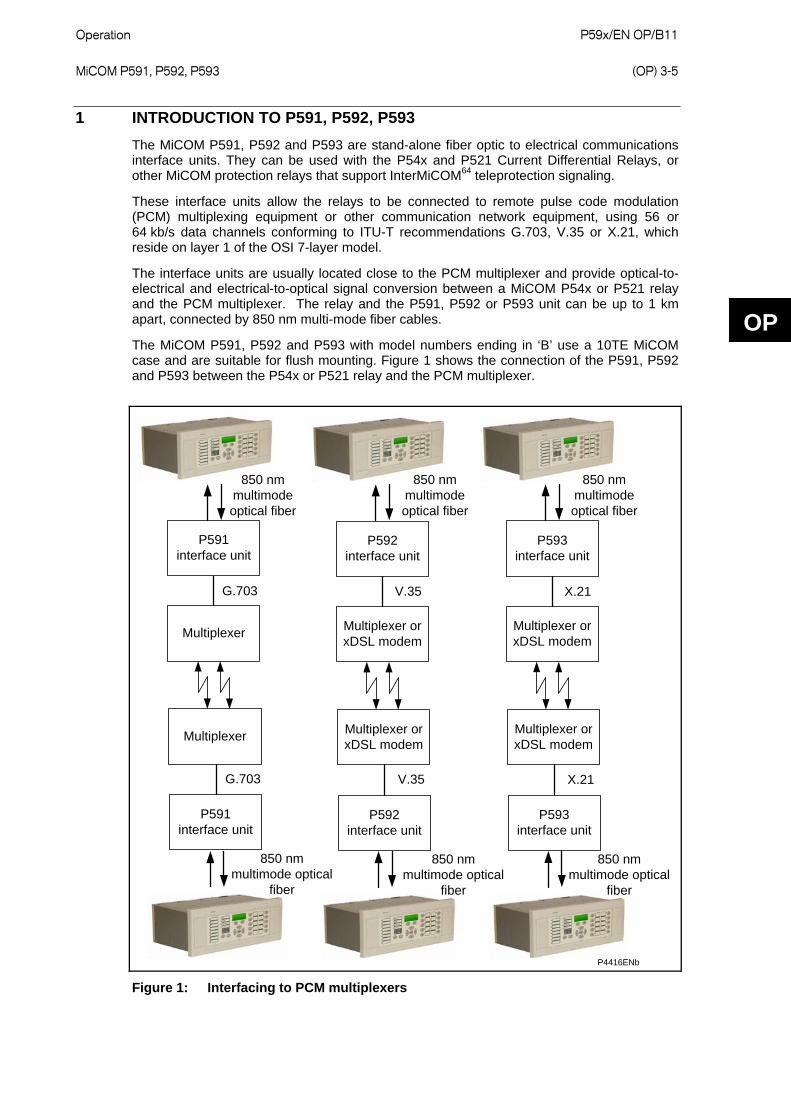
The MiCOM P591, P592 and P593 are stand-alone fiber optic to electrical communications interface units. They can be used with the P54x and P521 Current Differential Relays, or other MiCOM protection relays that support InterMiCOM64 teleprotection signaling.
These interface units allow the relays to be connected to remote pulse code modulation (PCM) multiplexing equipment or other communication network equipment, using 56 or 64 kb/s data channels conforming to ITU-T recommendations G.703, V.35 or X.21, which reside on layer 1 of the OSI 7-layer model.
The interface units are usually located close to the PCM multiplexer and provide optical-to-electrical and electrical-to-optical signal conversion between a MiCOM P54x or P521 relay and the PCM multiplexer. The relay and the P591, P592 or P593 unit can be up to 1 km apart, connected by 850 nm multi-mode fiber cables.
The MiCOM P591, P592 and P593 with model numbers ending in ‘B’ use a 10TE MiCOM case and are suitable for flush mounting. Figure 1 shows the connection of the P591, P592 and P593 between the P54x or P521 relay and the PCM multiplexer.
P591 interface unit
P593 interface unit
Multiplexer Multiplexer or xDSL modem
Multiplexer Multiplexer or xDSL modem
P591 interface unit
P593 interface unit
P592 interface unit
Multiplexer or xDSL modem
Multiplexer or xDSL modem
P592 interface unit
G.703 V.35 X.21
G.703 V.35 X.21
850 nm multimode optical fiber
850 nm multimode optical fiber
850 nm multimode optical fiber
850 nm multimode optical
fiber
850 nm multimode optical
fiber
850 nm multimode optical
fiber
P4416ENb
Figure 1: Interfacing to PCM multiplexers
OP
P59x/EN OP/B11 Operation (OP) 3-6
MiCOM P591, P592, P593
OP
1.1 G.703, V.35 and X.21 Interfaces
The following interfaces reside on the physical layer (layer 1) of the OSI 7-layer model. They are all ITU-T (formerly CCITT) synchronous serial interface standards and are used in this case at 56 to 64 kb/s. They all use differential signalling over twisted pairs.
Twisted pair cabling twists together the forward and return conductors of a single circuit. This cancels out electromagnetic interference such as noise, interference from Unshielded Twisted Pair (UTP) cables, and crosstalk between unshielded neighbouring pairs.
It is recommended to use Braided Shielded Twisted Pairs because they give better noise immunity and better mechanical strength compared to foils.
1.1.1 ITU-T G.703
G.703 is used over balanced 120 ohm twisted pair cables. In the 4-wire version there are two twisted pairs, each pair consisting of Transmit Data and Receive Data.
It is called co-directional because the data and timing are sent in the same direction over the same wires.
1.1.2 ITU-T V.35
V.35 is often used on wide area networking and telecommunications equipment. V.35 uses differential signalling on the data and clock lines in a twisted pair, however, the handshake leads are single-ended. Between two devices, connections A connect to A, and B connect to B.
When connecting a DTE to a DCE, the DCE normally supplies the clock. The DCE is normally a multiplexer or modem.
1.1.3 ITU-T X.21
X.21 is a circuit-switching state protocol and is often used on wide area networking and telecommunications equipment. Between two devices, connections A connect to A, and B connect to B. Hardware handshaking is done by the Control and Indication lines. The Control line is used by the DTE and the Indication line is used by the DCE
The Signal Element Timing is the clock signal, which is provided by the DCE. The DCE is normally a multiplexer or modem.

Operation P59x/EN OP/B11 MiCOM P591, P592, P593
(OP) 3-7
2 OPERATION OF THE P591, P592 AND P593
The P591, P592 and P593 are interface units which convert the optical output of the P54x relay to an electrical signal for a PCM multiplexer with G.703, V.35 or X.21 interfaces. The unit is housed in a size 10TE case and should be located near to the multiplexer.
Figure 2: P591, P592, P593 front panels
Figure 3: P591, P592, P593 rear panel
OP
P59x/EN OP/B11 Operation (OP) 3-8
MiCOM P591, P592, P593
OP
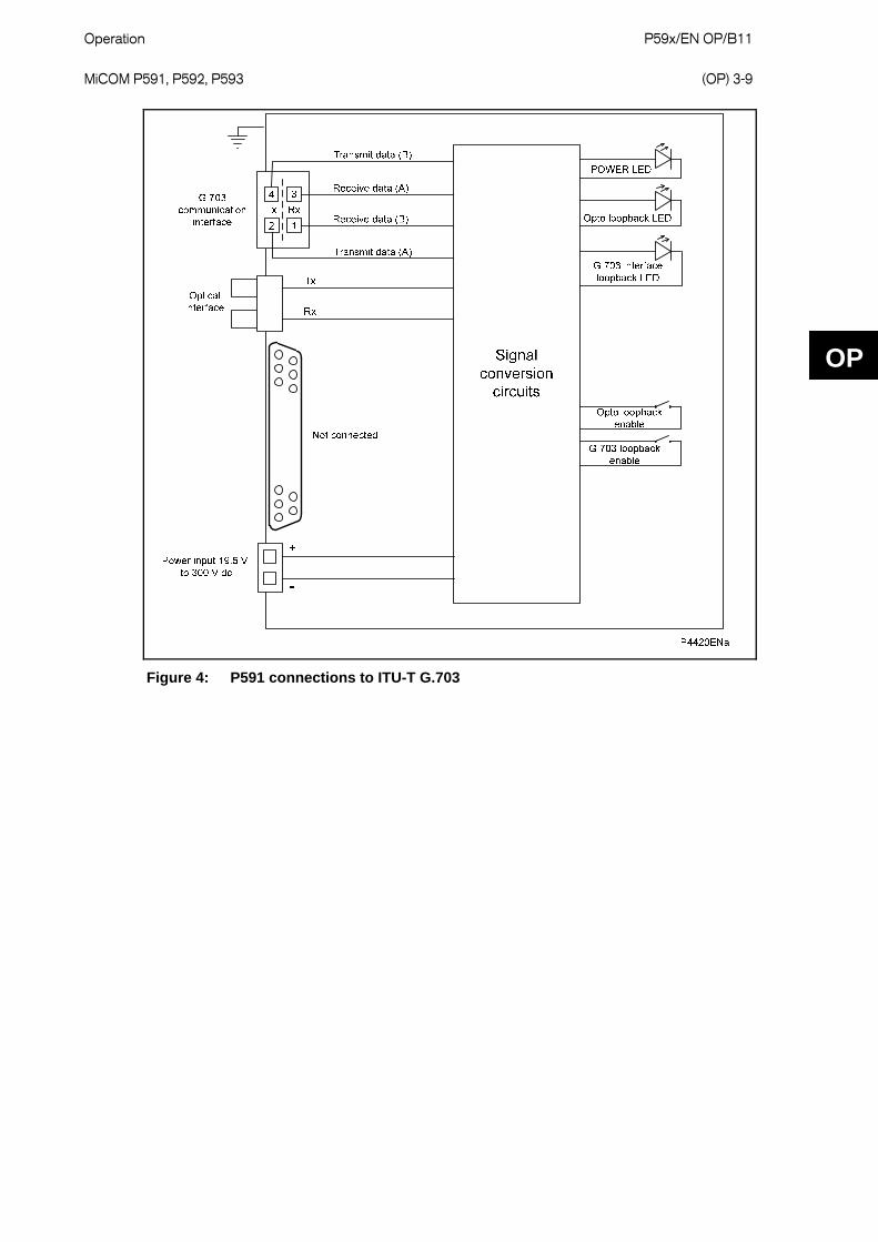
2.1 P591
The MiCOM P591 is stand-alone fiber optic to electrical communications interface unit. It allows a digital current differential relay to be connected through optical cables to remote PCM multiplexing equipment that has an ITU-T G.703 co-directional interface.
The front panel has three LEDs to show the status of the unit.
POWER is green and shows that the unit is correctly powered.
Opto Loopback is red if there is a communication loopback condition. Check for a break in the communications path between the two current differential relays.
G.703 interface loopback is red if there is a communication loopback condition. Check for a break in the communications path between the two current differential relays.
There are also two switches on the front panel:
Opto loopback enable/disable. This switch breaks the signal path between the optical received data and the optical transmitted data. The Opto Loopback switch also connects the signal from the optical receiver back to the optical transmitter, allowing the communication signal from the local current differential relay to be looped back for system testing. The red Opto Loopback LED is ON when this option is selected.
G.703 loopback enable/disable This switch breaks the signal path between the optical received data and the G.703 transmitted data. The G.703 Loopback switch also connects the signal from the G.703 receiver stage to the G.703 transmitter stage, allowing the G.703 data from the remote current differential relay to be looped back for system testing. The red G.703 Loopback LED is ON when this option is selected.
Note: The 25-pin connector is disabled.
The P591 connected to the fiber optic link must use the same timing for the transmit and receive signal. To ensure this, set the P54x Clock Source parameter to External Clock. The data bit is read on the clock rising edge.
Operation P59x/EN OP/B11 MiCOM P591, P592, P593
(OP) 3-9
Figure 4: P591 connections to ITU-T G.703
OP

P59x/EN OP/B11 Operation (OP) 3-10
MiCOM P591, P592, P593
OP
2.2 P592
The P592 is stand-alone fiber optic to electrical communications interface unit. It allows a digital current differential relay to be connected through optical cables to a remote telecommunications multiplexing equipment that has an ITU-T V.35 interface at 56 or 64 kb/s.
The front panel has five LEDs to show the status of the unit.
POWER is green and shows that the unit is correctly powered.
Opto Loopback is red if there is a communication loopback condition. Check for a break in the communications path between the two current differential relays.
V.35 interface loopback is red if there is a communication loopback condition. Check for a break in the communications path between the two current differential relays.
DSR OFF is red if the DSR override switch is set to Disable. DSR is normally asserted by the DCE to show the DCE is powered on and is ready to receive commands or data for transmission from the DTE.
CTS OFF is red if the CTS override switch is set to Disable. CTS is asserted by the DCE to acknowledge the RTS signal and allow the DTE to transmit.
The current differential relay requires an uninterrupted communication link, therefore in normal operation, all LEDs should be OFF except for the green power LED.
There are also six switches on the front panel.
Opto loopback, enable/disable. This switch breaks the signal path between the optical received data and the optical transmitted data. The Opto Loopback switch also connects the signal from the optical receiver back to the optical transmitter, allowing the communication signal from the local current differential relay to be looped back for system testing. The red Opto Loopback LED is ON when this option is selected.
V.35 loopback, enable/disable. This switch breaks the signal path between the optical received data and the V.35 transmitted data. The V.35 Loopback switch also connects the signal from the V.35 receiver stage to the V.35 transmitter stage, allowing the V.35 data from the remote current differential relay to be looped back for system testing. The red V.35 Loopback LED is ON when this option is selected.
DTE/DCE mode. Switches between the two modes. Data Communications Equipment (DCE) is typically a modem, multiplexer, router or switch. Data Terminal Equipment (DTE) is typically a user interface to a network such as a terminal or computer.
DSR override, enable/disable. This should only be enabled if the multiplexer or modem is not providing the DSR signal.
CTS override, enable/disable. This should only be enabled if the multiplexer or modem is not providing the DSR signal.
56/64 kb/s. Switches between the two data rates.
Note: The G.703 connector is disabled.
The P592 connected to the fiber optic link must use the same timing for the transmit and receive signal. To ensure this, set the P54x Clock Source parameter to External Clock. The data bit is read on the clock rising edge.

Operation P59x/EN OP/B11 MiCOM P591, P592, P593
(OP) 3-11
P4419ENa
Optical interface
Tx
Rx
Signal conversion
circuits
+
-
POWER LED
Opto loopback LED
V.35 interface loopback LED
DSR OFF LED
CTS OFF LED
Opto loopback enable
V.35 loopback enable
DTE/DCE
DSR OFF enable
CTS OFF enable
56/64 kbps
15 Transmit data (B)3 Receive data (A)16 Receive data (B)
4 RTS5 CTS6 DSR21 Transmit timing (A)9 Transmit timing (B)23 Terminal timing (A)10 Terminal timing (B)11 Receive timing (A)24 Receive timing (B)7 GND
2 Transmit data (A)
V.35 communication
interface
Power input 19.5 V to 300 V dc
G.703 communication
interfaceNot connected
Figure 5: P592 connections to ITU-T V.35
OP

P59x/EN OP/B11 Operation (OP) 3-12
MiCOM P591, P592, P593
OP
2.3 P593
The P593 is a stand-alone fiber optic to electrical communications interface unit. It allows a digital current differential protection relay, which has a fiber-optic communication interface, to be connected over digital communication links, conforming to the ITU-T recommendation X.21.
The front panel has four LEDs to show the status of the unit.
POWER is green and shows that the unit is correctly powered.
Opto Loopback is red if there is a communication loopback condition. Check for a break in the communications path between the two current differential relays.
X.21 interface loopback is red if there is a communication loopback condition. Check for a break in the communications path between the two current differential relays.
CLOCK is green and shows that the P593 is receiving the correct X.21 timing signal.
There are also two switches on the front panel.
Opto loopback, enable/disable. This switch breaks the signal path between the optical received data and the optical transmitted data. The Opto Loopback switch also connects the signal from the optical receiver back to the optical transmitter, allowing the communication signal from the local current differential relay to be looped back for system testing. The red Opto Loopback LED is ON when this option is selected.
X.21 loopback, enable/disable. This switch breaks the signal path between the optical received data and the X.21 transmitted data. The X.21 Loopback switch also connects the signal from the X.21 receiver stage to the X.21 transmitter stage, allowing the X.21 data from the remote current differential relay to be looped back for system testing. The red X.21 Loopback LED is ON when this option is selected.
Note: The G.703 connector is disabled.
The Signal Element Timing (input to P593 on pins 6 and 13) is used to clock both the transmit data and the receive data.
The P593 connected to the fiber optic link must use the same timing for the transmit and receive signal. To ensure this, set the P54x Clock Source parameter to External Clock. The data bit is read on the clock rising edge.
Ensure that the end-to-end polarity is consistent for the Signal Element Timing, Receive and Transmit lines.
Connect the Control (RTS) and Indication (CTS) lines to 0V.

Operation P59x/EN OP/B11 MiCOM P591, P592, P593
(OP) 3-13
P4421ENa
Signal conversion
circuits
POWER LED
Opto loopback LED
X.21 interface loopback LED
CLOCK LED
Opto loopback enable
X.21 loopback enable
Optical interface
Tx
Rx
+
-
Power input 19.5 V to 300 V dc
G.703 communication
interfaceNot connected
15 Transmit data (B)
3 Receive data (A)
16 Receive data (B)
4 Control (A)
24 Signal element timing (A)
11 Signal element timing (B)
17 Control (B)
7 GND
2 Transmit data (A)
X.21 communication
interface
OP
Figure 6: P593 connections ITU-T X.21

P59x/EN OP/B11 Operation (OP) 3-14
MiCOM P591, P592, P593
OP

Commissioning P59x/EN CM/B11 MiCOM P591, P592, P593
(CM) 4-1
CM
COMMISSIONING
Date: 9th October 2009
Hardware Suffix: B
Software Version:
Connection Diagrams: 10P59x02 x = 1 to 3

P59x/EN CM/B11 Commissioning (CM) 4-2
MiCOM P591, P592, P593
CM
Commissioning P59x/EN CM/B11 MiCOM P591, P592, P593
(CM) 4-3
CM
CONTENTS
1 INTRODUCTION 5
2 EQUIPMENT REQUIRED FOR COMMISSIONING 6
3 PRODUCT CHECKS 7
3.1 Visual inspection 7
3.2 Insulation 7
3.3 External wiring 7
3.4 Auxiliary supply 7
3.5 Light emitting diodes 8
4 FIBER COMMUNICATIONS 9
4.1 Communications using the P591 interface units 9
4.1.1 Light Emitting Diodes (LEDs) 9
4.1.2 Loopback test 9
4.2 Communications using the P592 interface units 11
4.2.1 Light Emitting Diodes 11
4.2.2 Loopback Test 11
4.3 Communications using the P593 interface units 12
4.3.1 Light Emitting Diodes 12
4.3.2 Loopback Test 12
5 FINAL CHECKS 13
6 COMMISSIONING TEST RECORD 14
7 SETTINGS RECORD 17
FIGURES
Figure 1 P591, P592, P593 front panels 8
Figure 2 P591, P592, P593 rear panel 8
Figure 3: P591 connections to ITU-T G.703 10
TABLES
Table 1 7 Operational range of auxiliary supply Vx

P59x/EN CM/B11 Commissioning (CM) 4-4
MiCOM P591, P592, P593
CM

Commissioning P59x/EN CM/B11 MiCOM P591, P592, P593
(CM) 4-5
1 INTRODUCTION
To commission the P59x, it is only necessary to verify that the hardware is functioning correctly.
Unless previously agreed to the contrary, the customer is responsible for determining the application specific switch settings to be applied to the unit.
Blank commissioning test and setting records are provided at the end of this chapter for completion as required.
Before carrying out any work on the equipment, the user should be familiar with the contents of the Safety Section or Safety Guide SFTY/4LM/H11 or later issue, the Technical Data chapter and the ratings on the equipment’s rating label.
CM

P59x/EN CM/B11 Commissioning (CM) 4-6
MiCOM P591, P592, P593
CM
2 EQUIPMENT REQUIRED FOR COMMISSIONING
Minimum equipment required:
Optical power meter
P54x relays
Commissioning P59x/EN CM/B11 MiCOM P591, P592, P593
(CM) 4-7
3 PRODUCT CHECKS
These product checks cover all aspects of the unit that need to be checked to ensure that it has not been physically damaged before commissioning and is functioning correctly. It may not be necessary to perform all output tests, depending on the application for which the P59x is used.
If the application-specific switch settings have been applied to the unit before commissioning, make a copy of the settings so they can be restored later. This is done by manually creating a setting record, using the copy at the end of this chapter.
3.1 Visual inspection
Check the rating information under the top access cover on the front of the relay to ensure that it is the correct model for the particular installation. Ensure that the circuit reference and system details are entered onto the setting record sheet.
Carefully examine the unit to see that no physical damage has occurred since installation. CMEnsure that the case earth (ground) connection, at the top of the rear of the case, is used to connect the unit to a local earthing bar using an adequate conductor.
3.2 Insulation
Insulation resistance tests are only necessary during commissioning if it is required for them to be done and they have not been performed during installation.
Isolate all wiring from the earth and test the insulation with an electronic or brushless insulation tester at a dc voltage not exceeding 500 V. The auxiliary dc supply terminals should be temporarily connected together.
The insulation resistance should be greater than 100 M at 500 V.
On completion of the insulation resistance tests, ensure that all external wiring is correctly reconnected to the P59x.
3.3 External wiring
Check the external wiring is correct according to the connection diagram in section 6 of the Installation chapter P59x/EN IN.
Check the dc supplies are wired with the correct polarity.
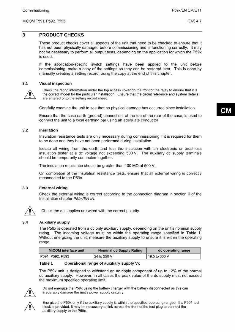
3.4 Auxiliary supply
The P59x is operated from a dc only auxiliary supply, depending on the unit’s nominal supply rating. The incoming voltage must be within the operating range specified in Table 1. Without energizing the unit, measure the auxiliary supply to ensure it is within the operating range.
MiCOM interface unit Nominal dc Supply Rating dc operating range
P591, P592, P593 24 to 250 V 19.5 to 300 V
Table 1 Operational range of auxiliary supply Vx
The P59x unit is designed to withstand an ac ripple component of up to 12% of the normal dc auxiliary supply. However, in all cases the peak value of the dc supply must not exceed the maximum specified operating limit.
Do not energize the P59x using the battery charger with the battery disconnected as this can irreparably damage the unit’s power supply circuitry.
Energize the P59x only if the auxiliary supply is within the specified operating ranges. If a P991 test
block is provided, it may be necessary to link across the front of the test plug to connect the auxiliary supply to the P59x.

P59x/EN CM/B11 Commissioning (CM) 4-8
MiCOM P591, P592, P593
3.5 Light emitting diodes
The MiCOM P591, P592 and P593 have several LEDs on the front panel to show the status of the unit.
The POWER LED is green and should normally be ON to indicate a healthy power supply. The other LEDs are red and are normally OFF.
Figure 1 P591, P592, P593 front panels
G.703 interface
P4418ENa
Opto Tx
V.35 or X.21 interface
DC power
Opto Rx
Chassis ground
Chassis ground
Figure 2 P591, P592, P593 rear panel
CM
Commissioning P59x/EN CM/B11 MiCOM P591, P592, P593
(CM) 4-9
CM
4 FIBER COMMUNICATIONS
4.1 Communications using the P591 interface units
The P591 converts the optical output of the P54x relay to an electrical signal for a PCM multiplexer with G.703 interfaces.
4.1.1 Light Emitting Diodes (LEDs)
At power up the green POWER LED goes ON and stays ON, showing that the P591 is healthy. See Figure 1.
To test the other two LEDs, use the switches on the unit’s front panel.
1. To switch ON the OPTO LOOPBACK and G.703 LOOPBACK LEDs, set their corresponding switches to Enable.
2. Once operation of the LEDs has been established, set all front panel switches to Disable.
4.1.2 Loopback test
1. Remove any external wiring from the G.703 terminals at the rear of each P591 unit. Loopback the G.703 signals on each unit by connecting a wire link between terminals Transmit data (A) and Receive data (A), and a second wire between terminals Transmit data (B) and Receive data (B). See Figure 3.
2. To measure and record the optical signal strength received by the P591, disconnect the optical fiber from the receive port on the rear of the unit and connect it to an optical power meter. The mean level should be from -18 dBm to -32 dBm. If the mean level is outside this range, check the size and type of fiber used.
3. Measure and record the optical output power of the transmit port of the P591 using the optical power meter and length of 50/125 μm optical fiber. The mean value should be from -14 dBm.
4. Ensure that the transmit (Tx) and receive (Rx) optical fibers between the P54x relay and P591 unit are connected. See Figure 2.
5. On the P54x relay, set cell [0F13 Test Loopback] to External. The relay then responds as if it is connected to a remote relay with the current at the remote end equal to and in phase with the current injected at the local end (no currents in the case of fiber InterMiCOM64).
6. Reset alarm indications. The relay then indicates a loopback alarm which can only be cleared by setting the loopback to Disabled. Channel status, propagation delays and communication statistics should be checked in the [MEASUREMENTS 4] column.
7. Set cell [0F15 IM64 Test Mode] to Enabled, cell [0F14 IM64 Test Pattern] to Enabled and set any Test Pattern. To verify the correct operation of loopback test, check in the [MEASUREMENTS 4] column that cell IM64 Rx Status matches the Test Pattern. The communication statistics indicate the number of valid and any error messages received. The propagation delay measurement is not valid in this mode of operation.
8. Alternatively use the internal loopback feature by setting cell [0F13 Test Loopback] to Internal loop and repeat the above test. In this mode it is not necessary to change the fiber.
Note: In loopback mode, the signals through the InterMiCOM64 interface are the signals defined in the programmable logic.
Note: To test the whole InterMiCOM64 communication path, set [0F15 IM64 Test Mode] to Enable and connect two ends. This sends a test pattern to the remote end. However, the test pattern will be excluded using a PSL at the remote end.

P59x/EN CM/B11 Commissioning (CM) 4-10
MiCOM P591, P592, P593
Figure 3: P591 connections to ITU-T G.703
CM
Commissioning P59x/EN CM/B11 MiCOM P591, P592, P593
(CM) 4-11
CM
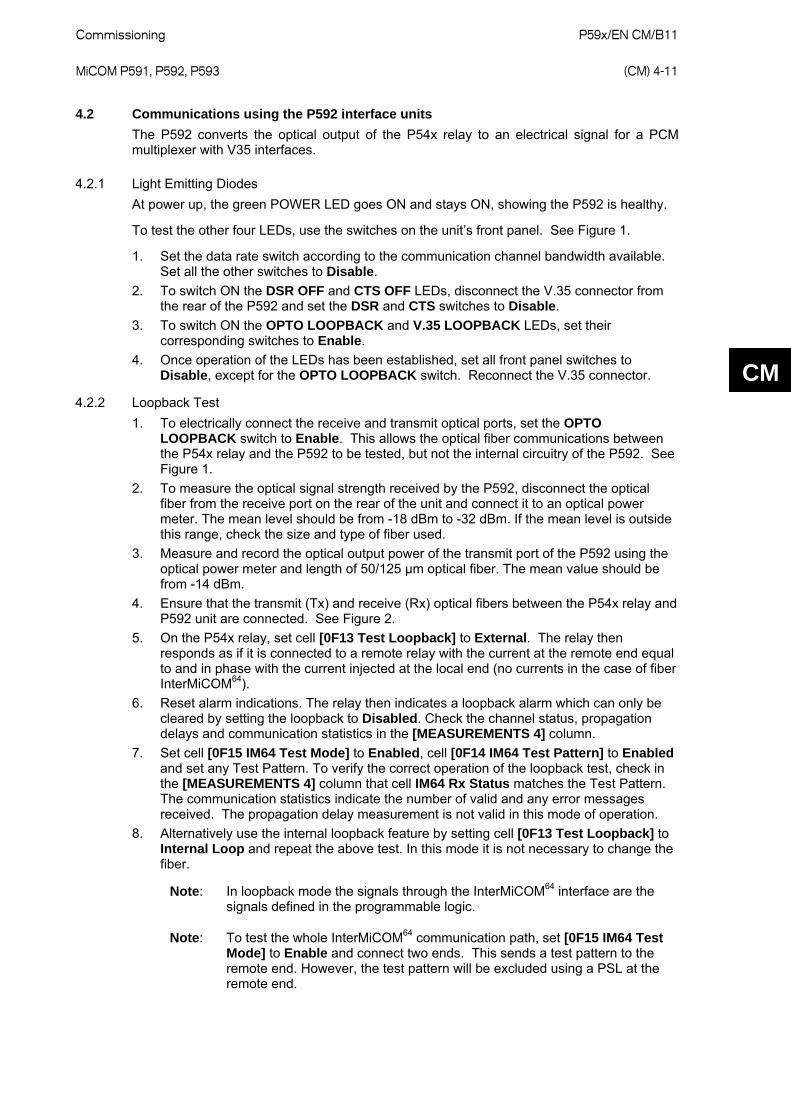
4.2 Communications using the P592 interface units
The P592 converts the optical output of the P54x relay to an electrical signal for a PCM multiplexer with V35 interfaces.
4.2.1 Light Emitting Diodes
At power up, the green POWER LED goes ON and stays ON, showing the P592 is healthy.
To test the other four LEDs, use the switches on the unit’s front panel. See Figure 1.
1. Set the data rate switch according to the communication channel bandwidth available. Set all the other switches to Disable.
2. To switch ON the DSR OFF and CTS OFF LEDs, disconnect the V.35 connector from the rear of the P592 and set the DSR and CTS switches to Disable.
3. To switch ON the OPTO LOOPBACK and V.35 LOOPBACK LEDs, set their corresponding switches to Enable.
4. Once operation of the LEDs has been established, set all front panel switches to Disable, except for the OPTO LOOPBACK switch. Reconnect the V.35 connector.
4.2.2 Loopback Test
1. To electrically connect the receive and transmit optical ports, set the OPTO LOOPBACK switch to Enable. This allows the optical fiber communications between the P54x relay and the P592 to be tested, but not the internal circuitry of the P592. See Figure 1.
2. To measure the optical signal strength received by the P592, disconnect the optical fiber from the receive port on the rear of the unit and connect it to an optical power meter. The mean level should be from -18 dBm to -32 dBm. If the mean level is outside this range, check the size and type of fiber used.
3. Measure and record the optical output power of the transmit port of the P592 using the optical power meter and length of 50/125 μm optical fiber. The mean value should be from -14 dBm.
4. Ensure that the transmit (Tx) and receive (Rx) optical fibers between the P54x relay and P592 unit are connected. See Figure 2.
5. On the P54x relay, set cell [0F13 Test Loopback] to External. The relay then responds as if it is connected to a remote relay with the current at the remote end equal to and in phase with the current injected at the local end (no currents in the case of fiber InterMiCOM64).
6. Reset alarm indications. The relay then indicates a loopback alarm which can only be cleared by setting the loopback to Disabled. Check the channel status, propagation delays and communication statistics in the [MEASUREMENTS 4] column.
7. Set cell [0F15 IM64 Test Mode] to Enabled, cell [0F14 IM64 Test Pattern] to Enabled and set any Test Pattern. To verify the correct operation of the loopback test, check in the [MEASUREMENTS 4] column that cell IM64 Rx Status matches the Test Pattern. The communication statistics indicate the number of valid and any error messages received. The propagation delay measurement is not valid in this mode of operation.
8. Alternatively use the internal loopback feature by setting cell [0F13 Test Loopback] to Internal Loop and repeat the above test. In this mode it is not necessary to change the fiber.
Note: In loopback mode the signals through the InterMiCOM64 interface are the signals defined in the programmable logic.
Note: To test the whole InterMiCOM64 communication path, set [0F15 IM64 Test Mode] to Enable and connect two ends. This sends a test pattern to the remote end. However, the test pattern will be excluded using a PSL at the remote end.

P59x/EN CM/B11 Commissioning (CM) 4-12
MiCOM P591, P592, P593
CM
4.3 Communications using the P593 interface units
The P593 converts the optical output of the P54x relay to an electrical signal for a PCM multiplexer with X.21 interfaces.
4.3.1 Light Emitting Diodes
At power up, the green POWER LED goes ON and stays ON, showing the P593 is healthy. To test the other three LEDs, use the switches on the unit’s front panel. See Figure 1.
1. Set the data rate switch to 56 or 64 kb/s, depending on the communication channel bandwidth available. Set all the other switches to Disable.
2. To switch off the CLOCK LED, disconnect the X.21 connector from the rear of the P592, so that the timing signal is lost.
3. To switch on the OPTO LOOPBACK and X.21 LOOPBACK LEDs, set their corresponding switches to Enable.
4. Once operation of the LEDs has been established, set all front panel switches to Disable, except for the OPTO LOOPBACK. Reconnect the V.35 connector.
4.3.2 Loopback Test
1. To electrically connect the receive and transmit optical ports, set the OPTO LOOPBACK switch to Enable. This allows the optical fiber communications between the P54x relay and the P593 to be tested, but not the internal circuitry of the P593. See Figure 1.
2. To measure and record the optical signal strength received by the P593, disconnect the optical fiber from the receive port on the rear of the unit and connect it to an optical power meter. The mean level should be from -18 dBm to -32 dBm. If the mean level is outside this range, check the size and type of fiber being used.
3. Measure and record the optical output power of the transmit port of the P593 using the optical power meter and length of 50/125 μm optical fiber. The mean value should be from -14 dBm.
4. Ensure that the transmit (Tx) and receive (Rx) optical fibers between the P54x relay and P593 unit are connected. See Figure 2.
5. Set the OPTO LOOPACK switch to Disable and the X.21 LOOPBACK switch to Enable. With the X.21 LOOPBACK switch in this position, the Receive Data and Transmit Data lines of the X.21 communication interface are connected together. This allows the optical fiber communications between the P54x relay and the P593, and the internal circuitry of the P593, to be tested.
6. On the P54x relay, set cell [0F13 Test Loopback] to External. The relay responds as if connected to a remote relay with the current at the remote end equal to and in phase with the current injected at the local end (no currents if using fiber InterMiCOM64).
7. Reset alarm indications. The relay shows a loopback alarm which can only be cleared by setting the loopback to Disabled. Check the channel status, propagation delays and communication statistics in the [MEASUREMENTS 4] column.
8. Set cell [0F15 IM64 Test Mode] to Enabled, cell [0F14 IM64 Test Pattern] to Enabled and set any Test Pattern. To verify the correct operation of loopback test, check in the [MEASUREMENTS 4] column that cell IM64 Rx Status matches the Test Pattern. The communication statistics indicate the number of valid and any error messages received. The propagation delay measurement is not valid in this mode of operation.
9. Alternatively use the internal loopback feature by setting cell [0F13 Test Loopback] to Internal Loop and repeat the above test. In this mode it is not necessary to change the fiber.
Note: In loopback mode the signals through the InterMiCOM64 interface are the signals defined in the programmable logic.
Note: To test the whole InterMiCOM64 communication path, set [0F15 IM64 Test Mode] to Enable and connect two ends. This sends a test pattern to the remote end. However, the test pattern will be excluded using a PSL at the remote end.

Commissioning P59x/EN CM/B11 MiCOM P591, P592, P593
(CM) 4-13
5 FINAL CHECKS
The tests are now complete.
Remove all test or temporary shorting leads. If it has been necessary to disconnect any of the external wiring from the unit to perform the wiring verification tests, make sure all connections are replaced according to the relevant external connection or scheme diagram.
CM
P59x/EN CM/B11 Commissioning (CM) 4-14
MiCOM P591, P592, P593
CM
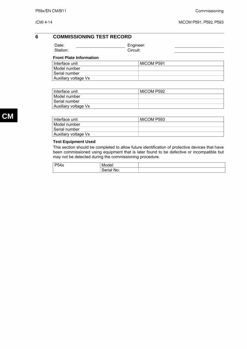
6 COMMISSIONING TEST RECORD
Date: Engineer: Station: Circuit:
Front Plate Information Interface unit MiCOM P591 Model number Serial number Auxiliary voltage Vx
Interface unit MiCOM P592 Model number Serial number Auxiliary voltage Vx
Interface unit MiCOM P593 Model number Serial number Auxiliary voltage Vx
Test Equipment Used This section should be completed to allow future identification of protective devices that have been commissioned using equipment that is later found to be defective or incompatible but may not be detected during the commissioning procedure.
Model: P54x Serial No:

Commissioning P59x/EN CM/B11 MiCOM P591, P592, P593
(CM) 4-15
CM
*Delete as appropriate
Have all relevant safety instructions been followed?
Yes* No*
3.1 Product visual inspection
Unit damaged? Yes* No*
Rating information correct? Yes* No*
Case earth installed? Yes* No*
3.2 Insulation resistance Yes* No*
Not Tested* N/A*
3.3 External wiring checked against diagram? Yes* No*
N/A*
3.4 Measured auxiliary supply Vdc/ac N/A*
4.1.1 All P591 LEDs working? Yes* No*
4.2.1 All P592 LEDs working? Yes* No*
4.3.1 All P593 LEDs working? Yes* No*
4.1.2 P591 loopback tests
Optical signal strength output dB
Optical signal strength received dB
4.2.2 P592 loopback tests
Optical signal strength output dB
Optical signal strength received dB
4.3.2 P593 loopback tests
Optical signal strength output dB
Optical signal strength received dB

P59x/EN CM/B11 Commissioning (CM) 4-16
MiCOM P591, P592, P593
CM
COMMENTS #
(# Optional, for site observations or utility-specific notes).
Commissioning Engineer Customer Witness
Date: Date:

Commissioning P59x/EN CM/B11 MiCOM P591, P592, P593
(CM) 4-17
CM
7 SETTINGS RECORD
Date: Engineer:
Station: Circuit:
Front plate information
Interface units MiCOM P591, P592, P593
Model number
Serial number
Auxiliary voltage Vx
SWITCH SETTING P591 Opto loopback Off On G.703 loopback Off On P592 Opto loopback Off On V.35 loopback Off On DSR Off On CTS Off On Data rate 56* 64* P593 Opto loopback Off On X.21 loopback Off On
Commissioning Engineer Customer Witness
Date: Date:

P59x/EN CM/B11 Commissioning (CM) 4-18
MiCOM P591, P592, P593
CM

Troubleshooting P59x/EN TS/B11 MiCOM P591, P592, P593
(TS) 5-1
TS
TROUBLESHOOTING
Date: 9th October 2009
Hardware Suffix: B
Software Version:
Connection Diagrams: 10P59x02 x = 1 to 3

P59x/EN TS/B11 Troubleshooting (TS) 5-2
MiCOM P591, P592, P593
TS
Troubleshooting P59x/EN TS/B11 MiCOM P591, P592, P593
(TS) 5-3
TS
CONTENTS
1 INTRODUCTION 5
2 PROBLEM IDENTIFICATION 6
2.1 P591 6
2.2 P592 7
2.3 P593 8
3 REPAIR AND MODIFICATION PROCEDURE 9
FIGURES
Figure 1: P591 problem identification 6
Figure 2: P592 problem identification 7
Figure 3: P593 problem identification 8

P59x/EN TS/B11 Troubleshooting (TS) 5-4
MiCOM P591, P592, P593
TS
Troubleshooting P59x/EN TS/B11 MiCOM P591, P592, P593
(TS) 5-5
1 INTRODUCTION
Before carrying out any work on the equipment, the user should be familiar with the contents of the Safety Section or Safety Guide SFTY/4LM/H11 or later issue, the Technical Data chapter and the ratings on the equipment’s rating label.
The purpose of this chapter is to identify an error condition on the P59x unit so that appropriate corrective action can be taken.
If a faulty P59x unit is returned to the manufacturer or one of their approved service centers, include a completed copy of the Repair or Modification Return Authorization (RMA) form at the end of this chapter.
TS

P59x/EN TS/B11 Troubleshooting (TS) 5-6
MiCOM P591, P592, P593
2 PROBLEM IDENTIFICATION
2.1 P591
POWER LED on?
G703 loopback LED on?
Comms working?
Switch G703 loopback on
Check G703 comms equipment or wiring to G703
connector
Switch fibre optic Loopback on
Comms working?
Check fibre optic interface of P591 and IED, and fibre optic cables. Use power meter and
test cable
N
Y
N
N
N
Y
Y
Y
Check aux power supply voltage,
wiring and fuses
Comms not working
P591 ok
P4426ENa
P591 faulty
Figure 1: P591 problem identification
TS

Troubleshooting P59x/EN TS/B11 MiCOM P591, P592, P593
(TS) 5-7
2.2 P592
POWER LED on?
Mux asserts DSR and CTS
signals?
Comms working?
Switch fibre optic Loopback on
Comms working?
Check fibre optic interface of P592 and IED, and fibre optic cables. Use power meter and
test cable
N
Y
N
N
N
Y
Y
Y
Check aux power supply voltage,
wiring and fuses
Comms not working
P592 faultyP592 ok
Mux supports DSR and
CTS?
Switch DSR and CTS switches off
DSR or CTS signal at input
to P592?
Is wiring from mux ok?
Check mux
N
Y
N
Y
N
Y
Fix wiring from mux
N
Y
V35 loopback LED on?
Switch V35 loopback on
Check V35 comms equipment
or wiring to V35 connector
Comms working?
N
Y
Configure mux
P4427ENa
Figure 2: P592 problem identification
TS

P59x/EN TS/B11 Troubleshooting (TS) 5-8
MiCOM P591, P592, P593
2.3 P593
POWER LED on?
CLOCK LED on?
X21 loopback LED on?
Comms working?
Switch X21 loopback on
Check X21 comms equipment
or wiring to X21 connector
Switch fibre optic Loopback on
Comms working?
Check fibre optic interface of P593 and IED, and fibre optic cables. Use power meter and
test cable
N
Y
N
N
N
N
Y
Y
Y
Y
Check aux power supply voltage,
wiring and fuses
Comms not working
P593 faultyP593 ok
P4428ENa
Figure 3: P593 problem identification
TS

Troubleshooting P59x/EN TS/B11 MiCOM P591, P592, P593
(TS) 5-9
TS
3 REPAIR AND MODIFICATION PROCEDURE
Please follow these steps to return an Automation product to us:
1. Get the Repair and Modification Authorization (RMA) form
For an electronic version of the RMA form, go to:
www.alstom.com/grid/productrepair/
2. Fill in RMA form
Fill in only the white part of the form.
Please ensure that all fields marked (M) are completed such as:
Equipment model
Model No. and Serial No.
Description of failure or modification required (please be specific)
Value for customs (in case the product requires export)
Delivery and invoice addresses
Contact details
3. Send the RMA form to your local contact
4. The local service contact provides the shipping information
Your local service contact provides all the information needed to ship the product:
Pricing details
RMA No.
Repair center address
If required, an acceptance of the quote must be delivered before going to next stage.
5. Send the product to the repair center
Address the shipment to the repair center specified by your local contact
Make sure all items are packaged in an anti-static bag and foam protection
Make sure a copy of the import invoice is attached with the returned unit
Make sure a copy of the RMA form is attached with the returned unit
E-mail or fax a copy of the import invoice and airway bill document to your local contact.

P59x/EN TS/B11 Troubleshooting (TS) 5-10
MiCOM P591, P592, P593
TS

Installation P59x/EN IN/B11 MiCOM P591, P592, P593
(IN) 6-1
IN
INSTALLATION
Date: 9th October 2009
Hardware Suffix: B
Software Version:
Connection Diagrams: 10P59x02 x = 1 to 3

P59x/EN IN/B11 Installation (IN) 6-2
MiCOM P591, P592, P593
IN
Installation P59x/EN IN/B11 MiCOM P591, P592, P593
(IN) 6-3
IN
CONTENTS
1 RECEIPT OF UNITS 5
2 HANDLING OF ELECTRONIC EQUIPMENT 6
3 STORAGE 7
4 UNPACKING 8
5 P59X CASE DIMENSIONS 9
6 CONNECTION DIAGRAMS 10
FIGURES
Figure 1: P59x case dimensions 9
Figure 2: P591 connections to ITU-T G.703 10
Figure 3: P592 connections to ITU-T V.35 11
Figure 4: V.35 DCE external clock 12
Figure 5: V.35 DTE internal clock 13
Figure 6: V.35 cable connections for 34-pin to 25-pin connectors 14
Figure 7: P593 connections to ITU-T X.21 15
Figure 8: X.21 cable connections 16
Figure 9: X.21 cable connections for 25-pin to 15-pin connectors 16

P59x/EN IN/B11 Installation (IN) 6-4
MiCOM P591, P592, P593
IN
Installation P59x/EN IN/B11 MiCOM P591, P592, P593
(IN) 6-5
IN
1 RECEIPT OF UNITS
On receipt, examine units immediately to ensure there has been no external damage in transit. If the unit has been damaged, make a claim to the transport contractor and notify ALSTOM Grid promptly.
P59x/EN IN/B11 Installation (IN) 6-6
MiCOM P591, P592, P593
2 HANDLING OF ELECTRONIC EQUIPMENT
Before carrying out any work on the equipment, the user should be familiar with the contents of the Safety Section or Safety Guide SFTY/4LM/H11 or later issue, the Technical Data chapter and the ratings on the equipment’s rating label.
A person’s normal movements can easily generate electrostatic potentials of several thousand volts. Discharge of these voltages into semiconductor devices when handling electronic circuits can cause serious damage that, although not always immediately apparent, reduces the reliability of the circuit. The unit’s electronic circuits are protected from electrostatic discharge when housed in the case. Do not expose them to risk by removing the front panel or printed circuit boards unnecessarily.
Each printed circuit board incorporates the highest practicable protection for its semiconductor devices. However, if it becomes necessary to remove a printed circuit board, the following precautions should be taken to preserve the high reliability and long life for which the unit has been designed and manufactured.
Before removing a printed board, ensure that you are at the same electrostatic potential as the equipment by touching the case.
Handle analog input modules by the front panel, frame or edges of the circuit boards. Printed circuit boards should only be handled by their edges. Avoid touching the electronic components, printed circuit tracks or connectors.
IN Do not pass the module to another person without first ensuring you are both at the same electrostatic potential. Shaking hands achieves this.
Place the module on an anti-static surface, or on a conducting surface that is at the same potential as yourself.
If it is necessary to store or transport printed circuit boards removed from the case, place them individually in electrically conducting anti-static bags.
In the unlikely event that you make measurements on the internal electronic circuitry of a unit in service, it is preferable that you are earthed (grounded) to the case with a conductive wrist strap. Wrist straps should have a resistance to ground of 500kΩ to 10MΩ. If a wrist strap is not available, keep frequent contact with the case to prevent a build-up of electrostatic potential. Instrumentation which may be used for making measurements should also be earthed (grounded) to the case.
Detailed investigations on electronic circuitry or modification work should be carried out in a special handling area. For more information on safe working procedures for all electronic equipment, see BS EN 100015: Part 1:1992.

Installation P59x/EN IN/B11 MiCOM P591, P592, P593
(IN) 6-7
IN
3 STORAGE
If units are not installed immediately on receipt, store them in a place free from dust and moisture in their original cartons. Keep any de-humidifier bags included in the packing.
On subsequent unpacking, make sure that any dust on the carton does not fall inside. In locations of high humidity the carton and packing may become impregnated with moisture and de-humidifier crystals will lose their efficiency.
Before installation, store units between -25˚C to +70˚C (-13˚F to + 158˚F).

P59x/EN IN/B11 Installation (IN) 6-8
MiCOM P591, P592, P593
4 UNPACKING
When unpacking and installing the units, take care not to damage any of the parts and make sure that additional components are not accidentally left in the packing or lost. Do not discard any technical documentation – this should accompany the unit to its destination substation.
Units must only be handled by skilled persons.
The site should be well lit to aid inspection, clean, dry and reasonably free from dust and excessive vibration. This particularly applies to installations that are being carried out at the same time as construction work.
IN
Installation P59x/EN IN/B11 MiCOM P591, P592, P593
(IN) 6-9
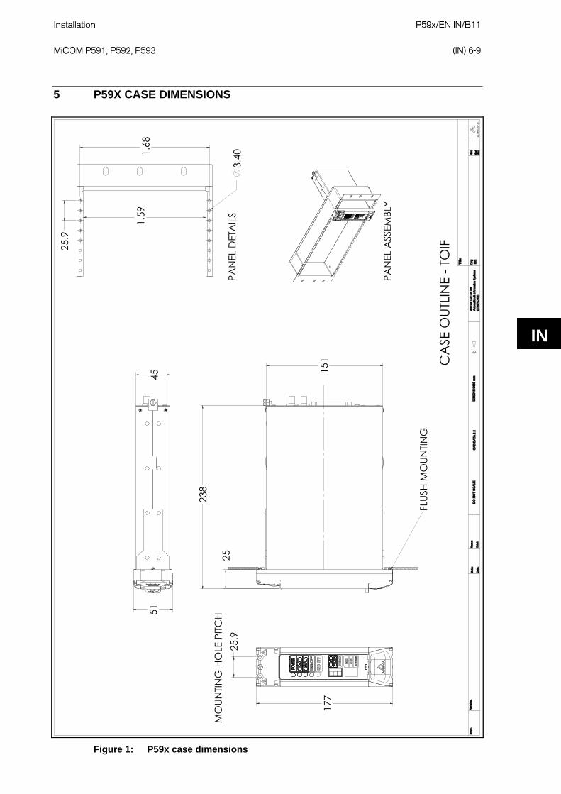
5 P59X CASE DIMENSIONS
!" #
$%%&
"'
(
IN
Figure 1: P59x case dimensions

P59x/EN IN/B11 Installation (IN) 6-10
MiCOM P591, P592, P593
6 CONNECTION DIAGRAMS
P591, P592 and P593
The case ground must be connected to the protective ground connector.
Optical connections are of BFOC 2.5 type unless otherwise specified.
For the communications cables it is recommended to use Braided Shielded Twisted Pairs because they give better noise immunity and better mechanical strength compared to foils.
P592 and 3
Equipment is normally supplied with 0 V common return signal and case ground electrically bonded. An internal soldered link can be removed to allow electrical isolation if required.
Figure 2: P591 connections to ITU-T G.703
IN

Installation P59x/EN IN/B11 MiCOM P591, P592, P593
(IN) 6-11
P4419ENa
Optical interface
Tx
Rx
Signal conversion
circuits
+
-
POWER LED
Opto loopback LED
V.35 interface loopback LED
DSR OFF LED
CTS OFF LED
Opto loopback enable
V.35 loopback enable
DTE/DCE
DSR OFF enable
CTS OFF enable
56/64 kbps
15 Transmit data (B)3 Receive data (A)16 Receive data (B)
4 RTS5 CTS6 DSR21 Transmit timing (A)9 Transmit timing (B)23 Terminal timing (A)10 Terminal timing (B)11 Receive timing (A)24 Receive timing (B)7 GND
2 Transmit data (A)
V.35 communication
interface
Power input 19.5 V to 300 V dc
G.703 communication
interfaceNot connected
Figure 3: P592 connections to ITU-T V.35
IN

P59x/EN IN/B11 Installation (IN) 6-12
MiCOM P591, P592, P593
Ground
0 Volt
RTS
CTS
DSR
TXD1
TXD2
RXD2
RXD1
STXC1
RXC1
RXC2
STXC2
TXC2
TXC1
(Shield) Ground
0 Volt
RTS
CTS
DSR
TXD1
RXD1
RXD2
TXD2
STXC1
RXC1
RXC2
STXC2
TXC2
TXC1
V.35 to MiCOM P592
V.35 to JMUX
P4422ENa.vsd
1
2
3
4
5
13
15
14
16
17
19
18
20
21
23
1
2
3
4
5
13
15
14
16
17
19
18
20
21
23
Figure 4: V.35 DCE external clock
IN

Installation P59x/EN IN/B11 MiCOM P591, P592, P593
(IN) 6-13
Figure 5: V.35 DTE internal clock
IN

P59x/EN IN/B11 Installation (IN) 6-14
MiCOM P591, P592, P593
ABCDEFHJKLMNPRSTUVWXYZ
AABBCCDDEEFFHHJJKKLLMMNN
12345678910111213141516171819202122232425
Data Terminal Ready
Send Data A
P4431ENa
Local Loopback
Local Test
Receive Data A
Receive Data B
Terminal Timing A
Receive Timing A
Chassis Ground
Signal Ground
Request to Send
Clear to Send
Data Set Ready
Data Carrier Detect
Send Data B
Terminal Timing B
Receive Timing B
Send Timing A
Send Timing B
Data Terminal Ready
Send Data A
Local Loopback
Local Test
Receive Data A
Receive Data B
Terminal Timing A
Receive Timing A
Chassis Ground
Signal Ground
Request to Send
Clear to Send
Data Set Ready
Data Carrier Detect
Send Data B
Terminal Timing B
Receive Timing B
Send Timing A
Send Timing B
MUX
P592
Figure 6: V.35 cable connections for 34-pin to 25-pin connectors
IN

Installation P59x/EN IN/B11 MiCOM P591, P592, P593
(IN) 6-15
Figure 7: P593 connections to ITU-T X.21
The Signal Element Timing (clock) is provided by the DCE. Hardware handshaking is done by the Control and Indication lines. The Control is used by the DTE and the Indication is used by the DCE.
IN

P59x/EN IN/B11 Installation (IN) 6-16
MiCOM P591, P592, P593
Control (A)
Mux P593
Transmit Data (A)
Transmit Data (B)
Receive Data (A)
Receive Data (B)
Signal Element Timing (A)
Signal Element Timing (B)
Control (B)
P4429ENa
123456789
10111213141516171819202122232425
123456789
10111213141516171819202122232425
Control (A)
Transmit Data (A)
Transmit Data (B)
Receive Data (A)
Receive Data (B)
Signal Element Timing (A)
Signal Element Timing (B)
Control (B)
Figure 8: X.21 cable connections
Figure 9: X.21 cable connections for 25-pin to 15-pin connectors
IN

Installation P59x/EN IN/B11 MiCOM P591, P592, P593
(IN) 6-17
IN

P59x/EN IN/B11 Installation (IN) 6-18
MiCOM P591, P592, P593
IN

PXXX Product Description
GRID
Alstom Grid
© - ALSTOM 2011. ALSTOM, the ALSTOM logo and any alternative version thereof are trademarks and service marks of ALSTOM. The other names mentioned, registered or not, are the property of their respective companies. The technical and other data contained in this document is provided for information only. Neither ALSTOM, its officers or employees accept responsibility for, or should be taken as making any representation or warranty (whether express or implied), as to the accuracy or completeness of such data or the achievement of any projected performance criteria where these are indicated. ALSTOM reserves the right to revise or change this data at any time without further notice.
Alstom Grid Worldwide Contact Centre
www.alstom.com/grid/contactcentre/
Tel: +44 (0) 1785 250 070
www.alstom.com