Michigan Criteria for On-Site 01-29-13 Final Edited Draft ...€¦ · 01-29-13 Final Edited Draft 2...
65
01-29-13 Final Edited Draft 0 Wastewater Treatment ~~~~~~~ Michigan Criteria for On-Site
Transcript of Michigan Criteria for On-Site 01-29-13 Final Edited Draft ...€¦ · 01-29-13 Final Edited Draft 2...

01-29-13 Final Edited Draft
0
Wastewater Treatment ~~~~~~~
Michigan Criteria for On-Site
01-29-13 Final Edited Draft
1
Table of Contents Introduction Chapter 1 – Administration, Purpose, and Applicability 1.1 Administration 1.2 Purpose 1.3 Applicability Chapter 2 – General Provisions 2.1 General 2.2 Construction Plans, Supervision, Inspection, and Approvals 2.2.1 System Designer Qualifications and Other Competent Professionals 2.2.2 Construction Plans 2.2.3 Construction Supervision 2.2.4 Construction Inspection and Final Approval 2.3 Public Sanitary Sewer and On-site/Decentralized System 2.4 Other Regulations Chapter 3 – Variances, Denials, and Appeals 3.1 Basis for Variance 3.2 Variance Procedures 3.3 Denials 3.4 Appeals Chapter 4 – Establishing Site Suitability for Soil Dispersal 4.1 General 4.2 Preapplication Meetings
4.3 Preliminary Site Evaluation
4.4 Field Site Evaluation 4.5 Site Evaluation Reporting/Final Site Plan and Evaluation 4.6 Dispersal Area Suitability 4.6.1 Soils 4.6.2 Soil Texture and Structure 4.6.3 Groundwater Mounding 4.6.4 Depth to High Groundwater Elevation 4.6.5 Reserve Area 4.6.6 Slope 4.6.7 Location and Horizontal Isolation 4.7 Soil Hydraulic Loading Rates and Linear Loading Rates 4.8 Isolation to High Groundwater Elevation 4.9 Use of Drainage Systems to Control High Groundwater Elevation 4.9.1 Drainage System Design and Construction 4.10 Demonstration of High Groundwater Elevation Control 4.10.1 Groundwater Elevation Monitoring 4.11 Excessively Permeable and Shallow Natural Soils 4.12 Deep Cut Excavations 4.12.1 Variance Criteria for Deep Cut Excavations
01-29-13 Final Edited Draft
2
Chapter 5 – Wastewater Characterization 5.1 Waste Strength Assessment
5.2 Facilities Generating High Strength Waste
5.3 Soil Loading Based on Organic Strength
5.4 Nutrient Considerations
5.5 Domestic Equivalent Activities
Chapter 6 – Establishing Wastewater Flows 6.1 General 6.2 Wastewater Flows for Community Systems Chapter 7 – Groundwater and Surface Water Protection
7.1 General
7.2 Groundwater Vulnerability
7.3 Surface Water Vulnerability
Chapter 8 – Treatment System Objectives 8.1 Treatment System Design Concepts 8.2 Treatment Objectives 8.3 Treatment Selection Based on Vulnerability Chapter 9 – Alternative Treatment Technologies 9.1 Nonproprietary Technology (public domain) 9.2 Proprietary Treatment Technology 9.3 Technology Listing Chapter 10 – System Management 10.1 System Management Plan 10.2 System Management Plan Content 10.3 System Management Objectives 10.4 Qualified Maintenance Providers Chapter 11 – Tank Design and Construction 11.1 General 11.2 Location 11.3 Tank Construction 11.4 Tank Sizing and Geometry 11.4.1 Septic Tank Design 11.4.2 Tank Considerations For High Strength Waste 11.5 Tank Inlets and Outlets 11.5.1 Tank Inlet and Outlet Piping 11.5.2 Tank Inlet/Outlet Baffles and Sanitary Tees 11.5.3 Effluent Filters 11.6 Access Risers and Lids 11.7 Tank Installation 11.8 Tank Watertightness Testing
01-29-13 Final Edited Draft
3
Chapter 12 – Pumps, Controls, and Appurtenances
12.1 General
12.2 Raw Sewage Pumping 12.3 Time Dosing 12.4 Demand Dosing 12.5 Distribution Valves 12.6 Number of Pumping Units 12.7 Pump Controls and Electrical Components 12.7.1 Basic Controls 12.7.2 Other Controls 12.7.3 Pump Control Panels and Location 12.7.4 Pumps and Electrical Hookups 12.7.5 Pump Floats and Switches 12.8 Pump Installation and Fittings 12.9 Effluent Pump Selection 12.10 Remote Monitoring 12.11 Flow Measurement 12.12 Use of Wastewater Siphons Chapter 13 – Flow Equalization 13.1 Introduction and Application 13.2 Flow Equalization Terminology 13.3 Placement of Flow Equalization 13.4 Establishing Equalization Storage Volume 13.5 Equalization Pump Control 13.6 Distribution of Final Effluent to Soil Dispersal Chapter 14 – Soil Dispersal System Design and Construction 14.1 Introduction 14.2 Gravity Distribution 14.3 Low Pressure Distribution 14.4 Drip Irrigation 14.5 Distribution Systems and Components 14.6 Septic Tank Effluent Pipe (for gravity flow) 14.7 Distribution Boxes 14.8 Drop Boxes 14.9 Mechanical Distribution Valves 14.10 Nonaggregate Systems 14.11 Final Cover and Grading
01-29-13 Final Edited Draft
4
Tables
4.1 Minimum Horizontal Isolation Distances 4.2 Soil Loading Rates For Infiltrative Surfaces 4.3 Dispersal System DESIGN Criteria 5.1 Residential Wastewater Strength 6.1 Community System Suggested Basis of Design 7.1 Aquifer Vulnerability 8.1 Treatment System Design Criteria 8.2 Treatment Objectives 8.3 Determining Treatment Objectives based on Vulnerability 10.1 System Management Objectives Definitions

01-29-13 Final Edited Draft
5
Introduction This document replaces the "Michigan Criteria for Subsurface Sewage Disposal” revision dated April 1994, published by the Michigan Department of Public Health. The criteria were developed by a constituent workgroup convened by the Michigan Department of Environmental Quality (DEQ) and included representation from local county and district health departments, academia, private sector consultants, and industry representatives. The criteria represents an overall change in philosophy intended to guide the department and authorized local health departments (LHD). The criteria are to be utilized in the approval of on-site wastewater systems at public and/or commercial facilities utilizing soil dispersal which treat sanitary sewage and/or domestic equivalent wastewater with flows up to 20,000 gallons per day (gpd). The criteria provides flexibility to allow consideration of both present and future technology that may become available. The revised criteria places strong emphasis on the need for professional competence. Rather than being totally prescriptive, the revised criteria establish a process for determining treatment objectives based upon risk. Provisions for long term operation and maintenance (O & M) are also stressed. Supplementing the criteria will be separate guidance documents to provide direction on topics of a nonproprietary nature which will be developed as needed over time with input of other on-site wastewater professionals from local health, academia and the private sector. Nationally there already exists a wealth of such information. As appropriate, where accepted guidance already exists, it will be cited for reference.
01-29-13 Final Edited Draft
6
Chapter 1 – Administration, Purpose, and Applicability 1.1 Administration This document has been established as a guideline pursuant to the requirements of the Administrative Procedures Act, 1969 PA 306, as amended. Guideline as defined therein means "An agency statement or declaration of policy which the agency intends to follow, which does not have the force or effect of law, and which binds the agency but does not bind any other person." It is intended that "agency" as used above also includes local health departments, when acting as an agent of the DEQ. The revised criteria communicates a standard by which decisions for approval of systems utilizing subsurface dispersal are made resulting in authorization to discharge pursuant to Part 31, Water Resources Protection, of the Natural Resources and Environmental Protection Act, 1994 PA 451, as amended (NREPA), and the Part 22 Groundwater Quality Administrative Rules, being R 323.2201 et seq., promulgated pursuant to Part 31. 1.2 Purpose The purpose of the criteria is to assure that the construction, operation and maintenance of on-site wastewater treatment systems utilizing soil dispersal in quantities of less than 20,000 gpd: 1. Are approved and constructed in a uniform manner consistent with the criteria. 2. Are routinely operated and maintained to assure proper treatment and function. 3. Will not contaminate any existing or future drinking water supply. 4. Will not give rise to a public health or safety hazard or present the potential for
creating a hazard. 5. Will not contaminate groundwater or surface water. 6. Will not give rise to a nuisance (e.g. due to odor or unsightly appearance). 7. Will not otherwise violate laws or regulations governing water pollution or sewage
disposal. 1.3 Applicability The revised criteria have been developed for use by the department and authorized LHD responsible for the consistent review and approval of on-site wastewater treatment systems with soil dispersal. The criteria are to provide minimum uniform review standards for approval of such systems in Michigan. Upon written request by a LHD, the DEQ may consider exemption to the criteria allowing for use of specific provisions of the local regulation. Exemptions shall be
01-29-13 Final Edited Draft
7
limited to conventional systems or systems utilizing pressure distribution only which treat residential strength wastewater in quantities less than 1,000 gpd. Exemptions may only be considered where it can be demonstrated that the local regulation as promulgated and adopted has provisions that are equivalent or more stringent than the criteria. The DEQ shall maintain and make available on its Web site a listing of the specific exemptions granted. It should be noted that these criteria pertain to the treatment and soil dispersal of sanitary sewage (e.g. toilet wastes, sink and laundry waste, and bath water) or domestic equivalent wastewater. The treatment and soil dispersal of wastes from industrial and commercial processes (e.g. laundromats, car washes, floor drains, etc.) requires specific Part 22 authorization by the DEQ. The criteria also do not apply to private single and two family residential sewage systems constructed pursuant to LHD sanitary codes. These criteria are applicable to approvals involving the following: 1. Proposals for construction of treatment systems at new structures;
2. Proposals for new or increased uses at existing structures; 3. Proposals to construct replacement systems where the existing system has failed; or 4. Replacement of existing systems for other reasons.
Chapter 2 – General Provisions 2.1 General Prior to the construction of a system under the criteria, construction approval, and required permits must be obtained from the agency having jurisdiction. Construction of the facility or modification of the site served by a soil dispersal system shall not begin until a construction permit and plan approval for the sewage system has been obtained from the authorized LHD and/or the DEQ under Part 22, or Part 41, Sewerage Systems, of the NREPA, if the system is a public system. In Michigan, state law mandates that notification be given to a utility locating service (e.g. Miss Dig) prior to any site excavations, borings, or tunneling to determine the location of nearby underground utilities. The review agency as a condition of a permit issued under these criteria shall require that this be complied with. 2.2 Construction Plans, Supervision, Inspections and Approvals 2.2.1 – System Designer Qualifications and Other Competent Professionals The design and submittal of plans for systems under the criteria should only be made by those licensed professional engineers or registered sanitarians, as allowed by law.
01-29-13 Final Edited Draft
8
These professionals must possess competence in wastewater treatment and soil dispersal systems gained through a combination of education and experience. Standards of practice and professional conduct require that for all phases of the project where the system designer lacks competence, the services of other competent professionals shall be retained. 2.2.2 – Construction Plans The agency shall require the submittal of detailed construction plans for all systems constructed under the criteria. The detailed construction plans are to be submitted to the agency after the site suitability, wastewater strength and design flow have been determined pursuant to Chapter 4, Chapter 5 and Chapter 6, respectively. The agency shall require that detailed plans have been prepared by either a licensed professional engineer or a registered sanitarian in private practice that are licensed or registered by the state of Michigan. The agency has the discretion to waive the submittal of detailed construction plans for small conventional systems or systems utilizing pressure distribution of septic tank effluent and which are expected to generate flows less than 1,000 gpd. For these situations, review and approval by the agency shall be completed under the supervision of a competent licensed professional engineer or registered sanitarian. 2.2.3 – Construction Supervision In cases where the agency has required the submission of detailed construction plans, as a condition of approval the agency shall also require that the system designer provide for the supervision of construction adequate to assure compliance with approved permit conditions, plans and specifications. The agency shall require written certification from the system designer that construction was completed in accordance with approved plans and specifications. System construction shall not deviate from the approved design unless authorized by the system designer and the agency. The agency shall ensure all deviation requests are made in writing. 2.2.4 – Construction Inspection and Final Approval The agency is to make such inspections as deemed necessary during construction to assure proper construction practices compliance with approved permit conditions, plans, and specifications or utilize an alternate process to accomplish this. Treatment system components including the soil dispersal system shall not be backfilled until the agency has given its approval unless waived by the agency due to mitigating circumstances. Waivers to the requirement for final inspection shall be documented in writing by the agency. The final approval of the system construction by the agency shall be withheld pending receipt of written certification from the system designer and documentation of a final inspection by the agency. 2.3 Public Sanitary Sewer and On-site/Decentralized System Connection to a public sanitary sewer system is required when available as defined by Section 12751 through 12758 of the Public Health Code, 1978 PA 368, as amended,
01-29-13 Final Edited Draft
9
being R 333.12751 through R 333.12758 of the Michigan Compiled Laws and when the local governmental entity having jurisdiction requires connection. Local governmental entities may also have planning that designates areas to be served by on-site/decentralized systems as the preferred wastewater infrastructure. Prior to evaluation of a site where the availability and requirement for connection to a public sewer system is in question, the agency shall require that the system designer obtain and submit a statement from the appropriate governmental entity regarding the availability of the sewer. 2.4 Other Regulations Beyond the approval gained pursuant to the revised criteria, it remains the responsibility of the owner, applicant or their agents to comply with any and all other applicable codes, rules, ordinances, or other criteria. Issuance of an approval under the criteria does not constitute approval, nor in any way authorize violation of other applicable federal, state, or local laws and regulations.
Chapter 3 – Variances, Denials and Appeals 3.1 Basis for Variance It is the intent of the criteria to provide minimum standards to be used in site evaluation and the design and construction of soil dispersal systems. However, there may be special circumstances which justify a variance from particular provisions. Such variances shall be granted by the DEQ or authorized LHD having jurisdiction when all the following are met: 1. Where the provisions contained within the criteria cannot be met or where strict
compliance is not required to meet the purpose of the criteria. 2. Where other more acceptable alternatives are not available. 3. Where the requested variance will not create the potential for a health hazard,
nuisance condition, or the pollution of groundwater or surface water, or otherwise violate the purpose of these criteria as stated in Section 1.2.
3.2 Variance Procedures The following procedure shall be followed in reviewing and granting requests for variances: 1. The applicant or designated representative shall file a written request with the DEQ
or authorized LHD. The request shall cite the specific provisions of the criteria for which the variance is requested. The variance request shall be supported by information describing the physical characteristics of the site, reasons for requesting the variance, and justification for granting the variance. Sufficient

01-29-13 Final Edited Draft
10
information to verify the protection of the public health, surface, and groundwater shall be provided.
2. The DEQ and the authorized LHD shall consult prior to granting a variance.
Written documentation of that consultation shall be made and maintained in both agencies’ files.
3. Variances may be granted by the DEQ for systems requiring DEQ construction
permits or DEQ approval. For all other systems variances may only be granted by the director of Environmental Health of an authorized LHD upon concurrence of the DEQ.
4. Variances granted for a specific project under consideration do not serve as
precedents in other cases. 3.3 Denials Before issuing a denial for a proposal to construct an on-site wastewater treatment system, the agency shall have information that site conditions or other factors will not allow for construction, operation, and maintenance of an on-site wastewater treatment system that satisfies compliance criteria found in Table 8.1. Furthermore, the Agency shall deny an application to construct an on-site wastewater treatment system when one or more of the following conditions are found to exist: 1. Information submitted is not sufficient to make a determination as to the suitability of
conditions for on-site wastewater treatment. 2. The agency determines that submitted information is in error with respect to
suitability for on-site wastewater treatment in accordance with these criteria. 3. Where connection to an available public sanitary sewer is required by the local unit
of government. 4. System components would be inaccessible for maintenance or repair. The agency shall issue a written denial to the applicant stating the specific reason(s) for denial. 3.4 Appeals Appeals of approvals or denials issued pursuant to the criteria may be made to the DEQ by filing of a request for contested case hearing pursuant to the Administrative Procedures Act.
01-29-13 Final Edited Draft
11
Chapter 4 – Establishing Site Suitability for Soil Dispersal 4.1 General Multiple factors establish the suitability for soil dispersal at a specific site. This section addresses these various site and soil factors which must be assessed during the initial site evaluation. All information gathered during the site evaluation process must be provided for review, with sufficient information to confirm the availability of an acceptable soil dispersal area and reserve area. This information also provides the basis for detailed design of the treatment and dispersal system. A contingency plan that does not include a reserve area may only be considered through a variance process described in Chapter 3. The agency shall not approve the site when site conditions inclusive of soils, high groundwater elevation, terrain, and/or area available for soil dispersal or other conditions will prevent the satisfactory operation of a system in a manner which fulfills the purpose of the criteria. Necessary field tests and evaluation of other factors by the agency shall be completed under the supervision of a licensed professional engineer or registered sanitarian to assess the suitability of a site. The site evaluation process should only be completed by agency staff and individuals in private practice who have competency in the design of on-site wastewater treatment systems or who have retained the services of other competent professionals. It is the responsibility of the system designer to coordinate the field aspects of the site evaluation with the agency. 4.2 Preapplication Meetings A preapplication meeting is an opportunity for the applicant or designated representative to meet with the system designer and the agency to discuss the proposed project. Such a meeting is most beneficial when it occurs early in the planning phase when a project proposal is defined enough to discuss it conceptually, but still flexible enough to incorporate recommendations from the meeting. The preapplication meeting can also be beneficial regardless of the projected flow for the facility. For facilities projected to produce wastewater flows in excess of 6,000 gpd, a preapplication meeting is strongly encouraged prior to completing the field site evaluation. Where projected flows exceed 10,000 gpd, the agency shall ensure a pre-application meeting be scheduled and conducted prior to completing the field site evaluation. The applicant or designated representative should provide and be prepared to discuss, the following information at the meeting: 1. Type of existing or proposed facility; anticipated flows and type or character of the
wastewater. 2. Location map - such as a county road map, showing the general location of the site. 3. General Site map - showing all existing and proposed features of the site.
01-29-13 Final Edited Draft
12
4. USDA soil survey map – identifying the predominant soil series of the site. (Map must include Township, Range, and Section)
5. Conceptual plans, if available. 4.3 Preliminary Site Evaluation
The agency shall require that a preliminary site evaluation is completed by the system designer prior to completing the field site evaluation. The preliminary site evaluation shall consist of gathering the information contained in Section 4.2 and the following additional information:
1. Existing and proposed buildings or improvements on the lot or site.
2. Documentation confirming the location of buried on-site utilities, if available. It is required that the system designer contact a utility locating service (e.g. Miss Dig).
3. Easements or deed restrictions on the site.
4. Current and past land use (if it can be determined).
5. The ordinary high water level of surface waters, if established. For on-site treatment systems of 6,000 gpd or more, the location of surface water which will be within 500 feet of the soil dispersal system(s) shall be documented.
6. Established 100 year floodplain elevation and boundary on the site if applicable.
7. A site survey including current and proposed property or boundary lines.
8. All required horizontal isolation distances from the proposed subsurface dispersal system as indicated in Table 4.1.
4.4 Field Site Evaluation
The agency shall assure that there is a coordinated joint field site evaluation with the system designer. The field site evaluation shall establish the following information:
1. Site boundaries. 2. Proposed and existing site improvements, required setbacks, and easements must
be identified. 3. Underground utilities must be located by calling a utility locating service (e.g. Miss
Dig) and other appropriate utilities before soil excavations and observations are undertaken.
01-29-13 Final Edited Draft
13
4. Topographic information and other factors that may influence dispersal system design.
5. Any evidence of cut or filled areas or disturbed or compacted soil. 6. The flooding or run-on potential to the proposed dispersal area(s). 7. A sufficient number of soil profile evaluations to confirm the existence of suitable
soils for both the initial and reserve soil dispersal areas with at least one soil observation performed in the portion of the soil dispersal area anticipated to have the most limiting conditions. However, a minimum of three soil observations are required for systems with design flows greater than 1,000 gpd. In areas of complex soils, additional evaluations may be necessary. The competent soil evaluator shall evaluate enough test pits to characterize soil type (per United States Department of Agricultural [USDA] classification) and conditions across both the initial and reserve soil dispersal areas.
8. Soil evaluations should be completed by observation of shallow soil pits of adequate
size, depth, and construction to safely enter and exit the pit and complete a soil profile description. With approval of the agency, a hand auger may be used for systems with flows less than 1,000 gpd and which will incorporate a soil dispersal component that is not dependent on soil structure. Other soil boring methods may be used with prior approval of the agency. If test pits are left open or unattended measures should be taken to secure against unauthorized entry. Note: Required safety precautions must be taken before entering soil test pits.
9. Each test pit must be prepared so that the soil profile can be viewed in an original
undisturbed position to a depth of at least six (6) feet; to a restrictive soil horizon or bedrock; or to the high groundwater elevation, whichever is shallower. Soil excavations shall always be of sufficient depth to provide adequate information for the design of the system.
10. Each soil profile observation must be evaluated under adequate light conditions with
the soil in a moist and unfrozen state. Optimally, soil evaluations should be completed during those time periods where soils are sufficiently dry and completed in a manner which avoids damage to the proposed absorption area.
11. The agency shall assure that soil evaluations must be completed and accurately
reported by a competent soil evaluator experienced with the USDA Soil Classification system. All of the following shall be reported: a. Soil horizon depths (as measured from the ground surface); b. Soil texture (per USDA soil classification system); c. Soil structure; d. Soil mottling;
e. Depth to high groundwater elevation or bedrock;
f. Groundwater levels observed at the time of the soil evaluation; and
01-29-13 Final Edited Draft
14
g. The reporting of soil color, using a Munsell soil color chart to describe the soil matrix, may be necessary based on proposed flows or other factors.
12. The agency shall assure that the location of all soil boring(s) or excavation(s)
completed on the site are documented in a verifiable manner. Each soil observation shall be located with measurements from two permanent reference points, or equivalent. A reliable benchmark shall be established on the site that can be used for horizontal and vertical control.
13. The agency shall assure that the boundaries of the proposed area for the soil
dispersal system(s) shall be visually marked. All proposed initial and reserve soil dispersal areas shall be protected from disturbance, compaction, or other damage by staking, fencing, posting, or other effective method as soon as practical.
4.5 Site Evaluation Reporting/Final Site Plan and Evaluation
Information gathered by the system designer/evaluator during the preliminary and field site evaluations shall be documented on a site report to the agency. The report shall also address any of the following if present:
1. Construction related issues such as rocks, tree stumps, high clay content soils, slope, and topography.
2. An initial recommendation of the type and number of soil dispersal areas, size of
those areas, system layout, dimensions, and distribution. 3. Any special design considerations (highly permeable soils (e.g. coarse sand),
floodplain, disturbed soil, low permeability soils (e.g. clay loams, etc.). 4. Impacts from upslope run-on areas. 5. Future surrounding land use changes (if known). 4.6 Dispersal Area Suitability 4.6.1 Soils – Areas to be utilized for soil dispersal shall consist of undisturbed natural
soils. 4.6.2 Soil texture and structure – Must be a suitable soil texture and structure as
indicated in Table 4.2 for which a soil hydraulic loading rate (see Section 4.7) has been shown.
4.6.3 Depth to high groundwater elevation – An 18-inch minimum isolation from the
undisturbed natural ground surface to high groundwater elevation over the entire area to be used for soil dispersal must be present. The depth to high groundwater elevation shall be confirmed by a soil profile with six (6) inches or more of soil without redoximorphic features (a.k.a. mottling) below the “A” horizon (topsoil). Groundwater elevation monitoring in accordance with Section 4.10 may
01-29-13 Final Edited Draft
15
also be considered. Increased vertical isolation to high groundwater may be necessary in consideration of groundwater elevation mounding.
4.6.4 Groundwater Mounding – For all sites the system designer shall consider the
potential for groundwater mounding that may occur as the result of the proposed discharge. In general, the potential for groundwater mounding will increase with the volume discharged and loading rate. Approval shall not be granted by the agency where groundwater mounding concerns cannot be mitigated through the soil-based dispersal system design which accounts for these site specific characteristics.
4.6.5 Reserve Area – For new or increased uses, an accessible area shall be
available and reserved to provide for a minimum of one replacement system without utilization or disruption of the initial installation. The reserve area shall be planned and maintained to facilitate replacement system installation, as needed.
4.6.6 Slope - Natural ground slope should be less than 25 percent in the system area
to promote safety of workers during construction. 4.6.7 Location and Horizontal Isolation – Table 4.1 identifies the minimum horizontal
isolation distances which shall be provided to allow proper installation, maintenance, and to be protective of the environment and public health. These minimums may only be increased based upon site specific conditions and the nature of the proposed discharge. Reduced isolation may be considered through the variance process described in Chapter 3.
4.6.8 100 year floodplain - the areas for initial and replacement on-site sewage
disposal systems shall have natural ground surface elevation above the elevation defining the 100-year floodplain, where a floodplain exists. The agency shall ensure that the soil infiltrative surface of the sewage disposal system is located at an elevation that is above the elevation defining the 100-year floodplain.

01-29-13 Final Edited Draft
16
Table 4.1 Minimum Horizontal Isolation Distances
From Soil Dispersal and Tank1 To: Minimum Horizontal Isolation Distance (feet)2
Type I Public Well 200
Type II-a Public Well 200
Type II-b Public Well 75
Type III Public Well 75
Private Individual Well 50
Other Wells 50
Surface Waters 100
Building Foundation or Basement Walls
10
Top of Drop-Off 20
Property Lines 10
Footing Drains Installed in Water Table Without Direct Connection to Surface Water
25
Footing Drains Installed in Water Table with Direct Connection to Surface Water
50
Drains Designed to Lower the Water Table
100
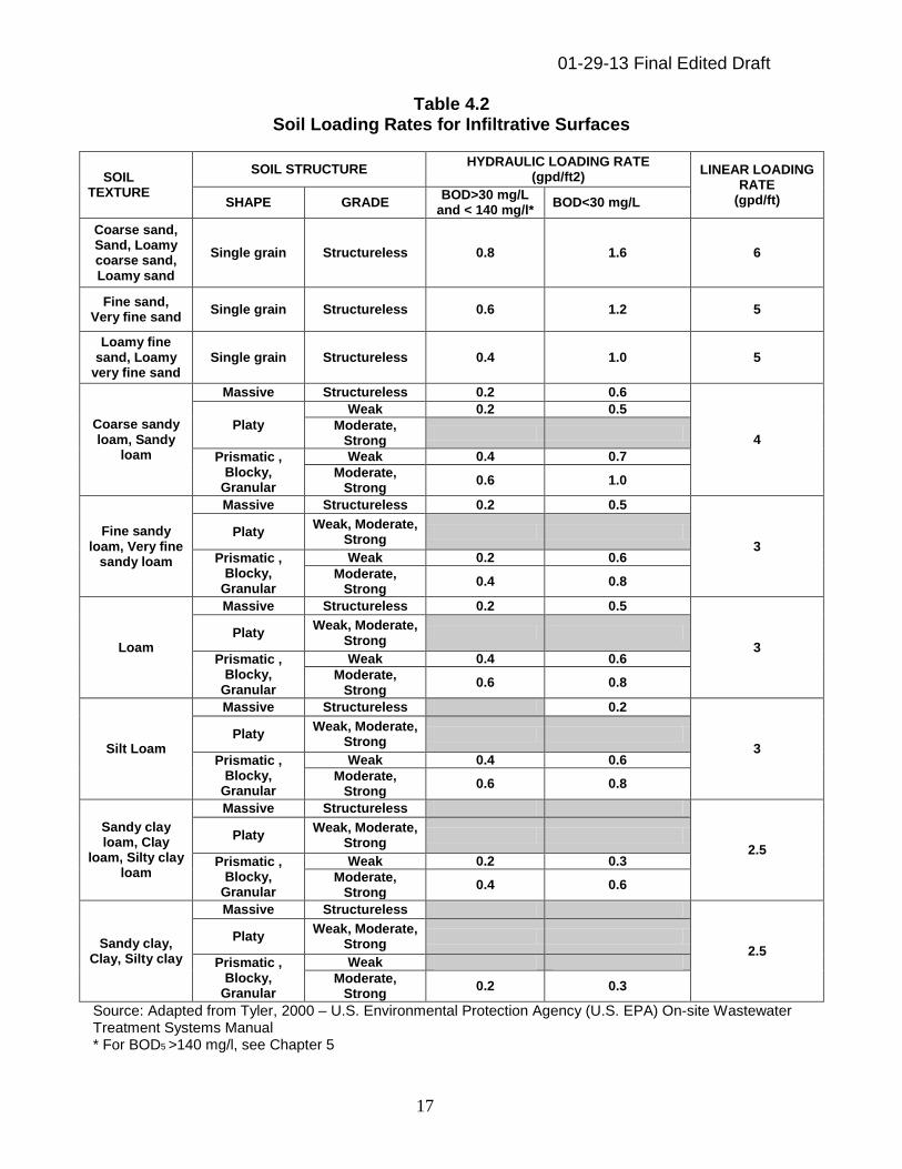
Pressurized Water Lines 10 1 as measured from perimeter of dispersal system or tank. 2 Increase may be required due to site specific conditions 4.7 Soil Hydraulic Loading Rates and Linear Loading Rates The system design must allow for soil hydraulic loading rates and linear loading rates as shown in Table 4.2. The soil hydraulic loading and linear loading rates shall be determined by the USDA soil texture and structure of the infiltrative surface or the most limiting soil texture as described in Table 4.2. The soil hydraulic and linear loading rates in Table 4.2 are not the only factors that must be considered in determining the acceptability of a design and layout of a soil-based dispersal system. Additional factors that must be considered in evaluating groundwater mounding potential include ground slope, available soil infiltrative depth above restrictive layers, and established high groundwater elevation. In general, the potential for groundwater mounding will increase with the volume and rate discharged.
01-29-13 Final Edited Draft
17
Table 4.2 Soil Loading Rates for Infiltrative Surfaces
SOIL TEXTURE
SOIL STRUCTURE HYDRAULIC LOADING RATE
(gpd/ft2) LINEAR LOADING
RATE (gpd/ft) SHAPE GRADE
BOD>30 mg/L and < 140 mg/l*
BOD<30 mg/L
Coarse sand, Sand, Loamy coarse sand, Loamy sand
Single grain Structureless 0.8 1.6 6
Fine sand, Very fine sand
Single grain Structureless 0.6 1.2 5
Loamy fine sand, Loamy
very fine sand Single grain Structureless 0.4 1.0 5
Coarse sandy loam, Sandy
loam
Massive Structureless 0.2 0.6
4 Platy
Weak 0.2 0.5
Moderate, Strong
Prismatic , Blocky,
Granular
Weak 0.4 0.7
Moderate, Strong
0.6 1.0
Fine sandy loam, Very fine
sandy loam
Massive Structureless 0.2 0.5
3 Platy
Weak, Moderate, Strong
Prismatic , Blocky,
Granular
Weak 0.2 0.6
Moderate, Strong
0.4 0.8
Loam
Massive Structureless 0.2 0.5
3 Platy
Weak, Moderate, Strong
Prismatic , Blocky,
Granular
Weak 0.4 0.6
Moderate, Strong
0.6 0.8
Silt Loam
Massive Structureless 0.2
3 Platy
Weak, Moderate, Strong
Prismatic , Blocky,
Granular
Weak 0.4 0.6
Moderate, Strong
0.6 0.8
Sandy clay loam, Clay
loam, Silty clay loam
Massive Structureless
2.5 Platy
Weak, Moderate, Strong
Prismatic , Blocky,
Granular
Weak 0.2 0.3
Moderate, Strong
0.4 0.6
Sandy clay, Clay, Silty clay
Massive Structureless
2.5 Platy
Weak, Moderate, Strong
Prismatic , Blocky,
Granular
Weak
Moderate, Strong
0.2 0.3
Source: Adapted from Tyler, 2000 – U.S. Environmental Protection Agency (U.S. EPA) On-site Wastewater Treatment Systems Manual * For BOD5 >140 mg/l, see Chapter 5
01-29-13 Final Edited Draft
18
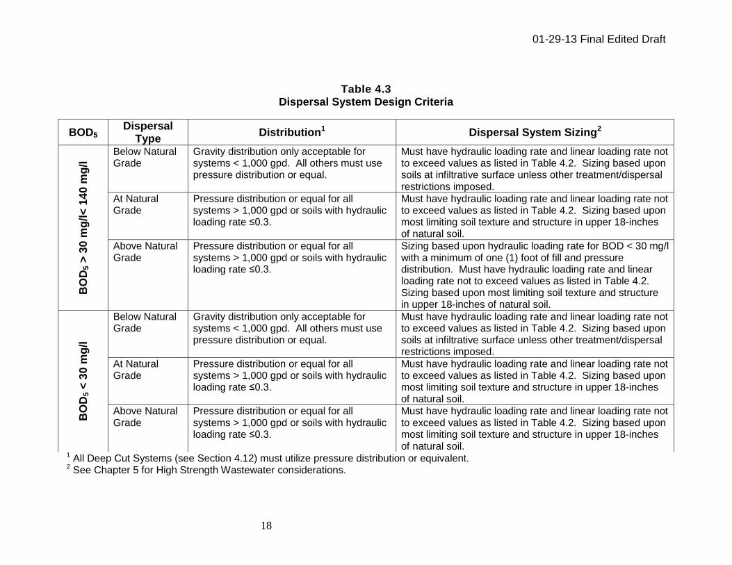
Table 4.3 Dispersal System Design Criteria
1 All Deep Cut Systems (see Section 4.12) must utilize pressure distribution or equivalent. 2 See Chapter 5 for High Strength Wastewater considerations.
BOD5 Dispersal
Type Distribution1 Dispersal System Sizing2
BO
D5 >
30
mg
/l<
14
0 m
g/l
Below Natural Grade
Gravity distribution only acceptable for systems < 1,000 gpd. All others must use pressure distribution or equal.
Must have hydraulic loading rate and linear loading rate not to exceed values as listed in Table 4.2. Sizing based upon soils at infiltrative surface unless other treatment/dispersal restrictions imposed.
At Natural Grade
Pressure distribution or equal for all systems > 1,000 gpd or soils with hydraulic loading rate ≤0.3.
Must have hydraulic loading rate and linear loading rate not to exceed values as listed in Table 4.2. Sizing based upon most limiting soil texture and structure in upper 18-inches of natural soil.
Above Natural Grade
Pressure distribution or equal for all systems > 1,000 gpd or soils with hydraulic loading rate ≤0.3.
Sizing based upon hydraulic loading rate for BOD < 30 mg/l with a minimum of one (1) foot of fill and pressure distribution. Must have hydraulic loading rate and linear loading rate not to exceed values as listed in Table 4.2. Sizing based upon most limiting soil texture and structure in upper 18-inches of natural soil.
BO
D5 <
30
mg
/l
Below Natural Grade
Gravity distribution only acceptable for systems < 1,000 gpd. All others must use pressure distribution or equal.
Must have hydraulic loading rate and linear loading rate not to exceed values as listed in Table 4.2. Sizing based upon soils at infiltrative surface unless other treatment/dispersal restrictions imposed.
At Natural Grade
Pressure distribution or equal for all systems > 1,000 gpd or soils with hydraulic loading rate ≤0.3.
Must have hydraulic loading rate and linear loading rate not to exceed values as listed in Table 4.2. Sizing based upon most limiting soil texture and structure in upper 18-inches of natural soil.
Above Natural Grade
Pressure distribution or equal for all systems > 1,000 gpd or soils with hydraulic loading rate ≤0.3.
Must have hydraulic loading rate and linear loading rate not to exceed values as listed in Table 4.2. Sizing based upon most limiting soil texture and structure in upper 18-inches of natural soil.
01-29-13 Final Edited Draft
19
4.8 Isolation to High Groundwater Elevation
To provide for adequate soil treatment capability, a minimum of three (3) feet of unsaturated soil shall exist between the bottom of the infiltrative surface and the high groundwater elevation or restrictive layer for residential strength wastewater (see Chapter 5). Greater vertical separation may be required in accordance with the regulations of the city, county, or district health department having jurisdiction under the authority granted by the Public Health Code, 1978 PA 368, as amended, being R 325.1101 et seq. of the Michigan Compiled Laws. Greater vertical separation may also be required where groundwater mounding underneath the soil absorption system or other factors would limit the treatment to protect groundwater or surface waters. For systems utilizing an approved alternative treatment technology, pursuant to Chapter 9, a one (1) foot reduction in vertical isolation is acceptable. 4.9 Use of Drainage Systems to Control High Groundwater Elevation The elevation of soil mottling and/or other redoximorphic features in a soil profile serve as primary indicators of the high groundwater elevation. Vertical isolation above high groundwater elevation and the infiltrative surface is necessary to allow treatment to occur. The agency may approve the use of a proposal that includes surface or subsurface gravity drainage systems to control high groundwater elevation conditions. This may entail the construction of new drainage systems or utilization of existing drainage systems on or nearby the site which is believed to have lowered the high groundwater elevation. 4.9.1 Drainage System Design and Construction
The design of the drainage system, either existing or proposed, shall be reviewed and may be approved by the agency. A responsible management entity (e.g. county drain commissioner) shall be identified to assure perpetual maintenance of the drainage system. 4.10 Demonstration of High Groundwater Elevation Control In instances where surface and subsurface drainage systems or other site factors are believed to have lowered the high groundwater elevation below that as indicated by soil mottling and/or other redoximorphic features, monitoring of the groundwater elevation may be used to demonstrate the lowered groundwater elevation. Prior to site approval, the system designer or their designated representative shall monitor high groundwater elevations during the normally wettest time period of the year and at least from March 1 to June 1. The system designer or their designated representative shall provide monitoring results to the agency.
01-29-13 Final Edited Draft
20
In addition, the system designer or their designated representative shall substantiate that high groundwater elevation has been lowered a minimum of 18-inches from the natural, unaltered grade over the entire initial and reserve areas proposed for soil dispersal. 4.10.1 Groundwater Elevation Monitoring The steps to be utilized for the monitoring of groundwater elevation are as follows: 1. Proposed monitoring well locations and design shall be reviewed and
approved by the agency prior to installation. 2. The agency shall have access to the site and monitoring wells during the
monitoring period as a condition of approval. After approval, the monitoring wells shall be installed at the approved locations and depths.
3. The system designer or their designated representative shall monitor and
record high groundwater elevations beginning the first day of the monitoring period and at least once every seven (7) days thereafter until the monitoring period is complete.
4. The system designer or their designated representative shall provide
representative precipitation data to the agency for the time period of September 1 to May 31 obtained from a verifiabled source.
5. The summary of the compiled data shall be submitted to the review agency. The results of high groundwater elevation monitoring are inconclusive if the recorded precipitation totals are less than 90 percent of normal averages during the time period of September 1 to May 31. 4.11 Excessively Permeable and Shallow Natural Soils
Excessively permeable soils are those having more than 60 percent of rock fragments, gravel, pebbles, or cobbles in a soil profile and have a preponderance of macro pores that allow wastewater constituents such as pathogens and nutrients to pass through the soil very rapidly. This is also the case where there are very shallow natural soils over fractured bedrock. These situations do not allow for adequate residence time required for the physical, chemical, and biological treatment within the soil body and therefore present concerns related to the contamination of groundwater supplies or surface waters. These situations may only be considered in conjunction with a careful and comprehensive evaluation of site specific environmental and public health concerns. In general, an alternative treatment system is warranted to address these concerns.

01-29-13 Final Edited Draft
21
4.12 Deep Cut Excavations Soil dispersal proposals utilizing deep cut excavations may only be approved by a variance from the agency granted in accord with Sections 3.1 and 3.23. 4.12.1 Variance Criteria for Deep Cut Excavations If suitable soils as specified in Table 4.2 are not present within the upper six (6) feet of the soil profile and alternative methods of sewage treatment and dispersal have been considered under Chapter 9 or Chapter 14, then the agency may approve a variance request for the use of deep cut excavations to expose acceptable underlying soils that exist within 20 feet of the natural grade must address all of the following: 1. Acceptable underlying soils shall consist of a minimum of four (4) feet of soils
which have a USDA texture no finer than sandy loam and which are not permanently or seasonally saturated as confirmed by soil profile evaluations and supportive hydrogeological information. Groundwater elevation monitoring as described in Section 4.10.1 should be utilized in situations where this information is inconclusive to the agency. Underlying soils shall be of sufficient areal extent to promote movement of treated effluent.
2. The level of treatment required prior to dispersal shall be established
pursuant to the requirements of Chapter 5 – Wastewater Characterization. 3. Discharge to the soil-based dispersal system shall be accomplished by
pressure distribution. 4. For deep cut excavations, the agency may require alternative methods of
sewage treatment (see Chapter 9). 5. The system design must allow for complete deep cut excavations over 100
percent of the required initial and reserve dispersal system area for the upper five (5) feet; however, excavations may be reduced to a minimum of 50 percent of the required dispersal system area between five (5) and 20 feet deep.
6. Deep cut excavations shall not cut through soils that are seasonally or
permanently saturated. Exceptions may be considered where a demonstration of the drainage of groundwater from overlying soils would not be expected to adversely impact the function of the soil-based dispersal system.
7. Hydrogeological information is provided that confirms that the underlying soils
being connected to have no direct hydraulic connection to a useable aquifer intended for drinking or household purposes.

01-29-13 Final Edited Draft
22
Chapter 5 – Wastewater Characterization 5.1 Waste Strength Assessment It is the responsibility of the system designer to assess waste strength for the facility. This can be accomplished by means of an estimation or actual assessment of waste strength. Primary sources of information include the facility itself when dealing with a system repair or increased use. Another source of information is comparative data obtained from similar facilities that is determined to be acceptable to the agency. Hydraulic performance, treatment performance, and longevity of a subsurface wastewater treatment system can be drastically affected by the wastewater composition. The strength of raw wastewater should be characterized for Biochemical Oxygen Demand (BOD5), Total Suspended Solids (TSS), Fats, Oils and Grease (FOG) and total nitrogen (TKN) (e.g. waste strength = BOD + TSS + FOG + TKN). Values for ammonia (nh4) and total phosphorous (tp) are also presented for reference. Typical values for influent wastewater and filtered primary septic tank effluent (FP) produced by residential dwellings are assumed to fall within those shown in Table 5.1 and need not be assessed further. Likewise, sanitary wastewater discharges from facilities without a process water component (e.g. retail, office space, manufacturing, etc.) would also be presumed to have strength falling within these values.
Table 5.1 Residential Wastewater Strength
Residential Wastewater
Influent Strength1
Typical FP2
BOD5 155 – 286 mg/l 100-140 mg/l
TSS 155 – 330 mg/l 20-55 mg/l
FOG 70 – 105 mg/l 10-20 mg/l
TKN 26-75 mg/l 50-90 mg/l
NH4 4-13 mg/l 30-50 mg/l
TP 6-12 mg/l 12-20 mg/l 1Source: EPA On-site Wastewater EPA/625/R-00/008 2Source: Crites Tchobanoglous, 1998 Small and Decentralized
Wastewater Management Systems System designs must account for concentrations of constituents that may be expected to exceed typical residential strength. The design must provide additional treatment which would be expected to produce effluent quality meeting required treatment objectives as referenced in section 8.2 prior to the soil dispersal component.
01-29-13 Final Edited Draft
23
5.2 Facilities Generating High Strength Waste Certain facilities can be expected to produce wastewater with high organic strength and elevated FOG characteristics. In particular, these high strength situations are associated with facilities where food preparation makes up a major part of their daily operation. Examples include restaurants, dining halls, bakeries, and grocery stores with deli and meat counters. These facilities are presumed to produce high strength wastewater unless acceptable representative data is otherwise provided by the system designer. The design for these facilities will typically make use of a pretreatment system in order to produce minimum effluent quality meeting the residential strength treatment objective prior to discharge to the soil dispersal system. In the absence of actual data representative of the waste strength from the facility and/or comparable facilities the agency will presume that filtered primary (FP) septic tank effluent will have the following minimum strength: 1. BOD5 – 1200 mg/L
2. TSS – 220 mg/L
3. FOG – 200 mg/L Source: Wisconsin Policy and Processing POWTS Plans April 2009 (still needs full reference citation) 5.3 Soil Loading Based on Organic Strength The traditional method of sizing a soil-based dispersal system area is based on appropriate hydraulic loading rates for site-specific soil characteristics, as shown in Table 4.2. These rates are based on effluent quality not exceeding residential strength of FP as indicated in Table 5.1. Wastewater with high organic strength requires special design consideration from the soil dispersal standpoint due the potential for soil clogging and/or clogging of the dispersal system components. To prevent soil clogging, research shows it is important to adjust the hydraulic loading rate and loading pattern. It is not always necessary to pre-treat high strength wastewater, since the organic loading rate can be considered in the design. In instances where pre-treatment is not utilized, the organic loading must be considered in sizing the soil dispersal system. The organic loading rate varies directly with BOD5. The following equation is provided as an adjustment factor to establish the soil hydraulic loading rate based proportionally on BOD5.
01-29-13 Final Edited Draft
24
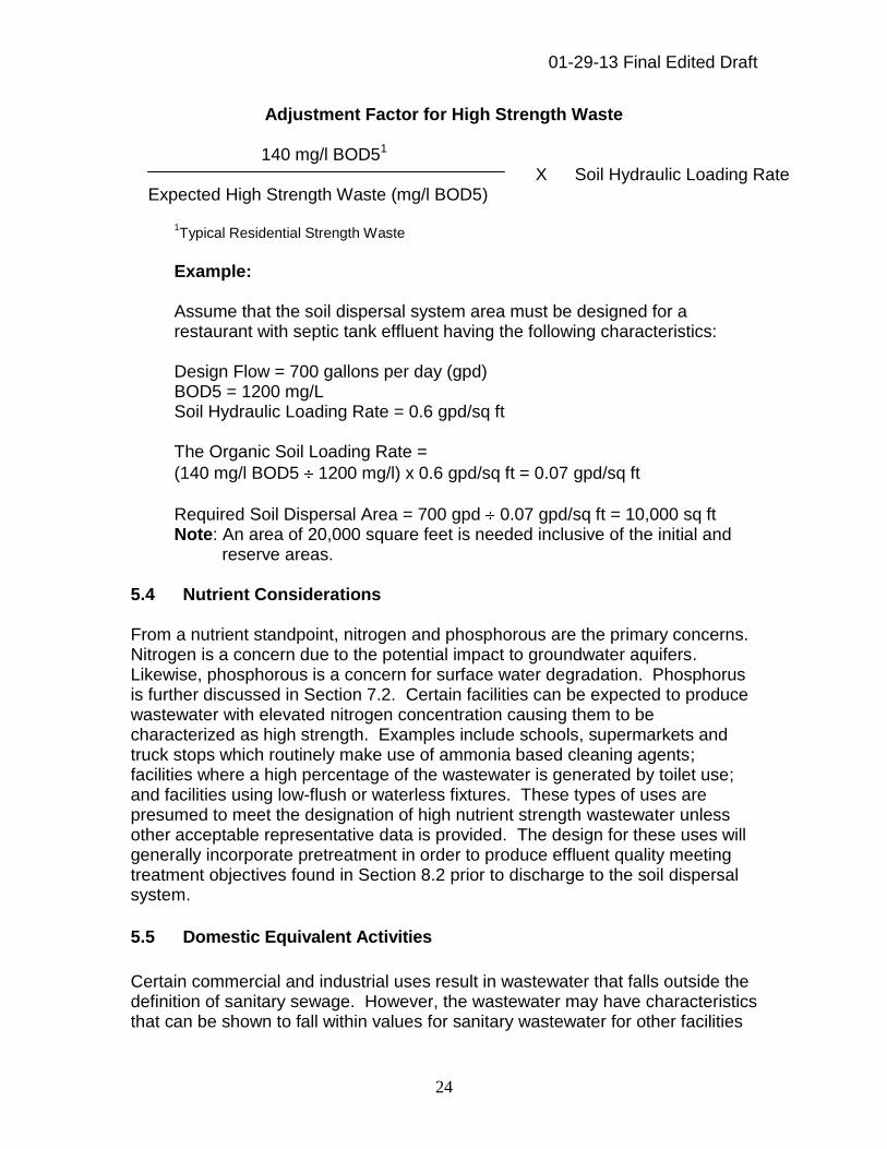
Adjustment Factor for High Strength Waste
140 mg/l BOD51 X Soil Hydraulic Loading Rate Expected High Strength Waste (mg/l BOD5)
1Typical Residential Strength Waste
Example: Assume that the soil dispersal system area must be designed for a restaurant with septic tank effluent having the following characteristics: Design Flow = 700 gallons per day (gpd) BOD5 = 1200 mg/L Soil Hydraulic Loading Rate = 0.6 gpd/sq ft The Organic Soil Loading Rate =
(140 mg/l BOD5 1200 mg/l) x 0.6 gpd/sq ft = 0.07 gpd/sq ft
Required Soil Dispersal Area = 700 gpd 0.07 gpd/sq ft = 10,000 sq ft Note: An area of 20,000 square feet is needed inclusive of the initial and
reserve areas. 5.4 Nutrient Considerations From a nutrient standpoint, nitrogen and phosphorous are the primary concerns. Nitrogen is a concern due to the potential impact to groundwater aquifers. Likewise, phosphorous is a concern for surface water degradation. Phosphorus is further discussed in Section 7.2. Certain facilities can be expected to produce wastewater with elevated nitrogen concentration causing them to be characterized as high strength. Examples include schools, supermarkets and truck stops which routinely make use of ammonia based cleaning agents; facilities where a high percentage of the wastewater is generated by toilet use; and facilities using low-flush or waterless fixtures. These types of uses are presumed to meet the designation of high nutrient strength wastewater unless other acceptable representative data is provided. The design for these uses will generally incorporate pretreatment in order to produce effluent quality meeting treatment objectives found in Section 8.2 prior to discharge to the soil dispersal system.
5.5 Domestic Equivalent Activities
Certain commercial and industrial uses result in wastewater that falls outside the definition of sanitary sewage. However, the wastewater may have characteristics that can be shown to fall within values for sanitary wastewater for other facilities

01-29-13 Final Edited Draft
25
considered under the criteria. On a case-by-case basis, and with DEQ concurrence, such wastewater may be considered for approval under the criteria and discharged to a soil dispersal system. Information must be supplied to the agency either derived from the facility itself or through comparative data that acceptably documents that the wastewater is of domestic equivalent as in Table 5.1 and suitable for treatment and groundwater discharge. Domestic equivalent flows may only be considered if the waste characteristics are suitable for discharge into the soil and comply with other applicable local, state, and federal regulations.
Chapter 6 – Establishing Wastewater Flow
6.1 General
The determination of wastewater design flow is one of the most important items in the planning of a new or expanded treatment system. Records of measurements of actual flow from existing installations or from similar establishments in similar locations should be used for system sizing when they can be obtained. In the absence of actual data, design flows for facilities noted in the “Onsite Treatment Systems Manual, 2002”, U.S. EPA, EPA/625/R-00/008 can be used as a guide, or other references that are acceptable may be used to determine anticipated flow volumes. These methods provide guidance on estimating the volume of sanitary sewage flow only. For systems anticipated to receive both sanitary sewage and domestic equivalent wastewater, the domestic equivalent volume must be determined separately based on actual flows or existing comparable use data. In all cases, the system design shall be based on peak daily flows, or equalized flows established pursuant to Chapter 13.
6.2 Wastewater Flows For Community Systems
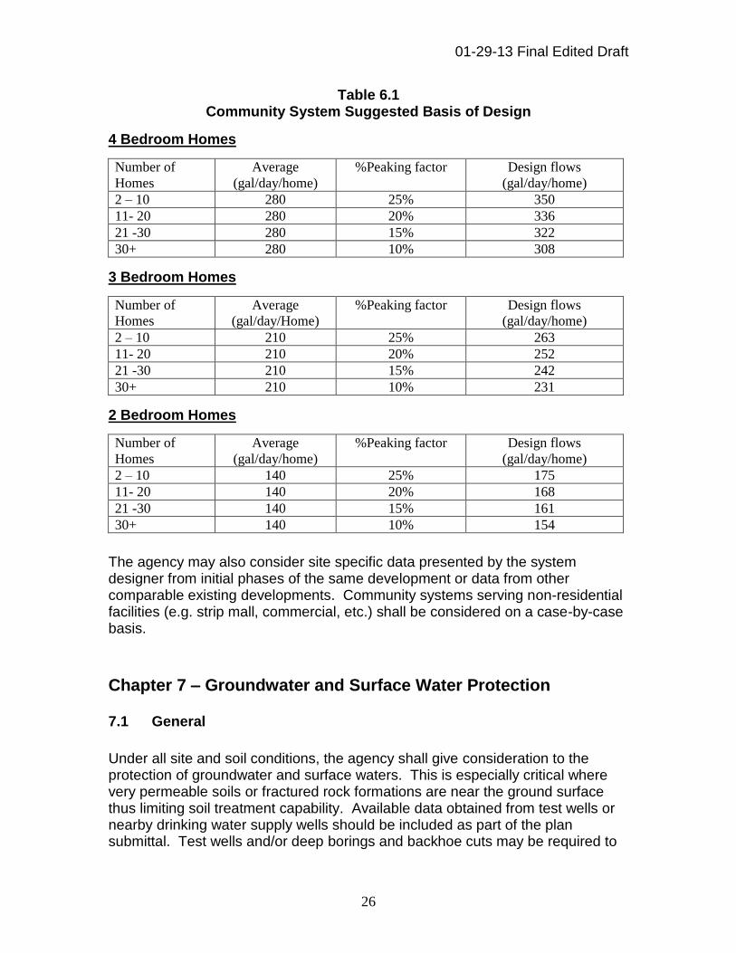
Typical community on-site wastewater systems are those that collect and treat sanitary sewage generated by multiple residential homes. Available data identify consistent average daily flows ranging from 65 – 75 gpd/bedroom. Table 6.1 suggests design flows assuming a consistent average flow of 70 gpd/bedroom and a variable peaking factor which decreases as the total number of homes served increases.
01-29-13 Final Edited Draft
26
Table 6.1 Community System Suggested Basis of Design
4 Bedroom Homes
Number of
Homes
Average
(gal/day/home)
%Peaking factor
Design flows
(gal/day/home)
2 – 10 280 25% 350
11- 20 280 20% 336
21 -30 280 15% 322
30+ 280 10% 308
3 Bedroom Homes
Number of
Homes
Average
(gal/day/Home)
%Peaking factor
Design flows
(gal/day/home)
2 – 10 210 25% 263
11- 20 210 20% 252
21 -30 210 15% 242
30+ 210 10% 231
2 Bedroom Homes
Number of
Homes
Average
(gal/day/home)
%Peaking factor
Design flows
(gal/day/home)
2 – 10 140 25% 175
11- 20 140 20% 168
21 -30 140 15% 161
30+ 140 10% 154
The agency may also consider site specific data presented by the system designer from initial phases of the same development or data from other comparable existing developments. Community systems serving non-residential facilities (e.g. strip mall, commercial, etc.) shall be considered on a case-by-case basis.
Chapter 7 – Groundwater and Surface Water Protection
7.1 General
Under all site and soil conditions, the agency shall give consideration to the protection of groundwater and surface waters. This is especially critical where very permeable soils or fractured rock formations are near the ground surface thus limiting soil treatment capability. Available data obtained from test wells or nearby drinking water supply wells should be included as part of the plan submittal. Test wells and/or deep borings and backhoe cuts may be required to

01-29-13 Final Edited Draft
27
determine the available site conditions providing for the protection of groundwater and surface waters.
The potential risk for contamination of groundwater aquifers and nearby surface waters increases as the volume of wastewater discharged increases. The agency is responsible to assure that during the planning and design phase, these risks are evaluated on an individual, case-by-case basis to establish the minimum treatment objective and soil dispersal. Based upon an established risk, alternative treatment may be incorporated into the design of the system as necessary to reduce the nitrogen and/or phosphorous in the final effluent to a level that is expected to be protective of both groundwater and surface waters. An evaluation of the site for both groundwater and surface water vulnerability is a key component in determining potential risk and defining the required minimum treatment objective.
7.2 Groundwater Vulnerability
In all instances, for any system being designed, constructed, operated, and maintained under the criteria, it shall be substantiated that groundwater quality of usable aquifers is protected for existing or future use. Categorizing aquifer vulnerability can range from a very basic assessment of available water supply well records, to in-depth and detailed hydrogeological studies. In general, the need for a more rigorous evaluation increases as the volume of discharge increases. Assessment of groundwater vulnerability is completed by review of site specific information, including but not limited to the review and consideration of the following: 1. Surface soil texture and permeability; 2. Presence or absence of confining layers of sufficient areal extent between the
soil-based dispersal system and uppermost usable aquifers; 3. Horizontal isolation afforded to existing and future water supply wells; 4. Direction of groundwater flow/venting; and/or 5. Depth to high groundwater elevation. Groundwater vulnerability may be established by consideration of the surface soil textures first and the presence/absence of confining layers. Groundwater vulnerability should be established based upon a review of the land area within a quarter mile radius of the proposed soil-based dispersal system unless it has been elected to conduct a detailed hydrogeological assessment.
01-29-13 Final Edited Draft
28
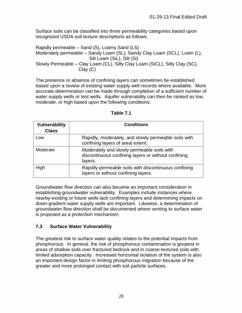
Surface soils can be classified into three permeability categories based upon recognized USDA soil texture descriptions as follows: Rapidly permeable – Sand (S), Loamy Sand (LS) Moderately permeable – Sandy Loam (SL), Sandy Clay Loam (SCL), Loam (L),
Silt Loam (SiL), Silt (Si) Slowly Permeable – Clay Loam (CL), Silty Clay Loam (SICL), Silty Clay (SC),
Clay (C) The presence or absence of confining layers can sometimes be established based upon a review of existing water supply well records where available. More accurate determination can be made through completion of a sufficient number of water supply wells or test wells. Aquifer vulnerability can then be ranked as low, moderate, or high based upon the following conditions:
Table 7.1
Vulnerability
Class
Conditions
Low Rapidly, moderately, and slowly permeable soils with confining layers of areal extent.
Moderate Moderately and slowly permeable soils with discontinuous confining layers or without confining layers.
High Rapidly permeable soils with discontinuous confining layers or without confining layers.
Groundwater flow direction can also become an important consideration in establishing groundwater vulnerability. Examples include instances where nearby existing or future wells lack confining layers and determining impacts on down-gradient water supply wells are important. Likewise, a determination of groundwater flow direction shall be documented where venting to surface water is proposed as a protection mechanism.
7.3 Surface Water Vulnerability
The greatest risk to surface water quality relates to the potential impacts from phosphorous. In general, the risk of phosphorous contamination is greatest in areas of shallow soils over fractured bedrock and in coarse-textured soils with limited adsorption capacity. Increased horizontal isolation of the system is also an important design factor in limiting phosphorous migration because of the greater and more prolonged contact with soil particle surfaces.

01-29-13 Final Edited Draft
29
Beyond establishing the location of the final dispersal system which meets or exceeds minimum horizontal isolation established in Table 4.1, each site should be further evaluated to assess the potential risk for phosphorous impact based upon site specific conditions and other factors that may include the following: 1. Anticipated flow volume. 2. Pre-treatment to reduce phosphorous prior to discharge to the soil-based
dispersal system. 3. The natural capacity of the soils to uptake phosphorous and the total volume
of soil that the wastewater is expected to contact. 4. Direction of groundwater flow, the rate of water movement, and high
groundwater elevation fluctuation. In general, the risk associated with phosphorous will increase with the flow volume and proximity to surface water. For systems with flows exceeding 6,000 gpd the agency shall determine the need for a site specific evaluation where the final dispersal system will be within 500 feet of surface waters.
Chapter 8 – Treatment System Objectives
8.1 Treatment System Design Concepts
The overall design of the treatment system inclusive of soil dispersal must address the waste character and site conditions. Compliance criteria in
Table 8.1 apply to treatment systems with soil dispersal. Once the design concept has been selected, the agency shall require that a detailed design of the system’s specific components be submitted. The design is to be reviewed by the agency in accordance with standards and guidance prescribed herein.
01-29-13 Final Edited Draft
30
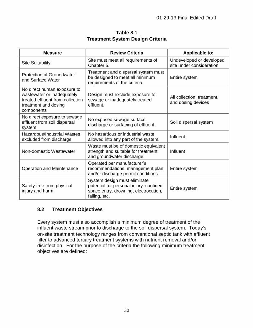
Table 8.1
Treatment System Design Criteria
Measure Review Criteria Applicable to:
Site Suitability Site must meet all requirements of Chapter 5.
Undeveloped or developed site under consideration
Protection of Groundwater and Surface Water
Treatment and dispersal system must be designed to meet all minimum requirements of the criteria.
Entire system
No direct human exposure to wastewater or inadequately treated effluent from collection treatment and dosing components
Design must exclude exposure to sewage or inadequately treated effluent.
All collection, treatment, and dosing devices
No direct exposure to sewage effluent from soil dispersal system
No exposed sewage surface discharge or surfacing of effluent.
Soil dispersal system
Hazardous/Industrial Wastes excluded from discharge
No hazardous or industrial waste allowed into any part of the system.
Influent
Non-domestic Wastewater Waste must be of domestic equivalent strength and suitable for treatment and groundwater discharge.
Influent
Operation and Maintenance Operated per manufacturer’s recommendations, management plan, and/or discharge permit conditions.
Entire system
Safety-free from physical injury and harm
System design must eliminate potential for personal injury: confined space entry, drowning, electrocution, falling, etc.
Entire system
8.2 Treatment Objectives
Every system must also accomplish a minimum degree of treatment of the influent waste stream prior to discharge to the soil dispersal system. Today’s
on-site treatment technology ranges from conventional septic tank with effluent filter to advanced tertiary treatment systems with nutrient removal and/or disinfection. For the purpose of the criteria the following minimum treatment objectives are defined:
01-29-13 Final Edited Draft
31
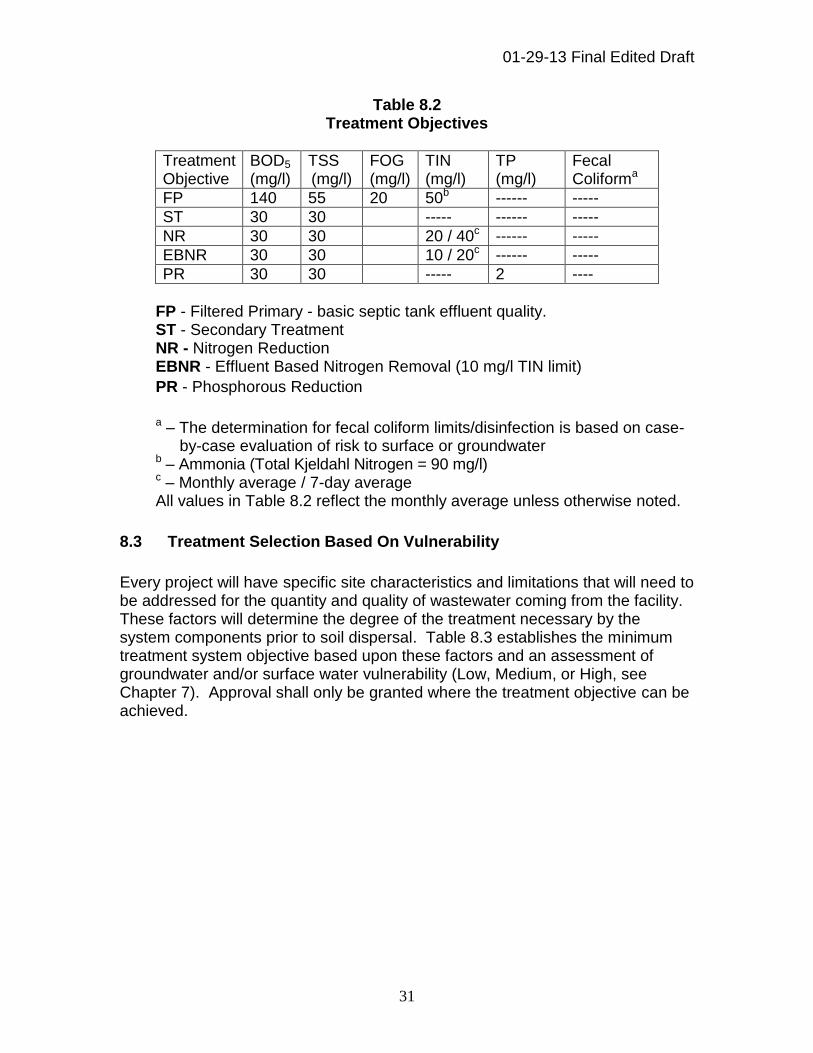
Table 8.2 Treatment Objectives
Treatment Objective
BOD5 (mg/l)
TSS (mg/l)
FOG (mg/l)
TIN (mg/l)
TP (mg/l)
Fecal Coliforma
FP 140 55 20 50b ------ -----
ST 30 30 ----- ------ -----
NR 30 30 20 / 40c ------ -----
EBNR 30 30 10 / 20c ------ -----
PR 30 30 ----- 2 ----
FP - Filtered Primary - basic septic tank effluent quality. ST - Secondary Treatment NR - Nitrogen Reduction EBNR - Effluent Based Nitrogen Removal (10 mg/l TIN limit)
PR - Phosphorous Reduction
a – The determination for fecal coliform limits/disinfection is based on case-
by-case evaluation of risk to surface or groundwater b – Ammonia (Total Kjeldahl Nitrogen = 90 mg/l) c – Monthly average / 7-day average All values in Table 8.2 reflect the monthly average unless otherwise noted.
8.3 Treatment Selection Based On Vulnerability
Every project will have specific site characteristics and limitations that will need to be addressed for the quantity and quality of wastewater coming from the facility. These factors will determine the degree of the treatment necessary by the system components prior to soil dispersal. Table 8.3 establishes the minimum treatment system objective based upon these factors and an assessment of groundwater and/or surface water vulnerability (Low, Medium, or High, see Chapter 7). Approval shall only be granted where the treatment objective can be achieved.

01-29-13 Final Edited Draft
32
Table 8.3 Determining Treatment Objective Based on Vulnerability
FLOW (gpd)→ 0-1000 >1000-6000 >6000-10000 >10000-20000
GROUNDWATER
VULNERABILITY→ L M H L M H L M H L M H
WA
ST
EW
AT
ER
CH
AR
AC
TE
R
Domestic FP FP FP or
NR FP ST EBNR ST NR EBNR ST NR EBNR
High Organic FP FP NR FP NR EBNR ST NR EBNR ST NR EBNR
High Nitrogen FP or
NR
FP or
NR NR
FP
or
ST
NR EBNR NR NR EBNR NR NR EBNR
SURFACE WATER
VULNERABILITY→ L M H L M H L M H L M H
-- -- PR -- -- PR -- PR PR -- PR PR
L = Low M = Medium H = High Treatment Objective: FP - Filtered Primary - basic septic tank effluent quality ST - Secondary Treatment NR - Nitrogen Reduction EBNR - Effluent Based Nitrogen Removal (10 mg/l TIN limit)
PR - Phosphorous Reduction
01-29-13 Final Edited Draft
33
Chapter 9 – Alternative Treatment Technologies
9.1 Nonproprietary Technology (public domain)
Nonproprietary technologies include any wastewater treatment or distribution technology, method, or material not subject to a patent or trademark which significantly contributes to the attainment of the treatment objectives as discussed in Chapter 8. Such technologies are designed and built in accord with generally accepted practice pursuant to specific technical guidance provided by the department or other generally accepted technical guidance recognized by the department. Sand filters and pressure mounds would be examples of technologies classified as nonproprietary.
9.2 Proprietary Treatment Technology
Proprietary treatment technology include any treatment product held under patent or trademark which significantly contributes to the treatment performance and attainment of effluent quality objectives as indicated in Table 8.2, Minimum Treatment Objectives. The system designer shall verify to the satisfaction of the agency that the proprietary product can be expected to meet treatment objectives for the defined wastewater characteristics and site conditions. Verification shall be supported by the following information: 1. Manufacturer: name, mailing address, street address, and phone number;
2. Manufacturer Contact: individual's name, mailing address, street address, and
phone number. The contact individual must be vested with the authority to represent the manufacturer in this capacity;
3. Name, including specific brand and model, of the proprietary treatment
product; 4. A description of the function of the proprietary treatment product along with
any known limitation on the use of the product;
5. Product description and technical information, including process flow drawings and schematics; materials and characteristics; component design specifications; design capacity, wastewater characteristics, volumes and flow assumptions, and calculations; components; dimensioned drawings and photos;
6. Detailed description, procedure, and schedule of routine service and system
maintenance events;
7. Copies of product brochures and manuals: Sales and Promotional; Design; Installation; Operation and Maintenance; and Owner Instructions, etc.;

01-29-13 Final Edited Draft
34
8. The most recently available product test protocol and third party results report
(E.G. National Sanitation Foundation (NSF) Standard 40, NSF Standard 245, Environmental Technology Verification Program or independent third party results);
9. A signed and dated certification by the manufacturer's agent specifically
including the following statement language:
"I certify that I represent (insert MANUFACTURING COMPANY NAME) and I am authorized and do hereby attest, under penalty of law, that this document and all attachments are true, accurate, and complete. I understand and accept that the product testing results reported with this application for registration are the parameters and values to be used for determining conformance with Treatment Objective (insert APPLICABLE OBJECTIVES). We have reviewed the intended usage of our product for this defined wastewater characteristic and are supportive of installation";
10. A list of representatives and/or manufacturer certified installers and service
providers.
11. A signed copy of the maintenance contract with a certified maintenance provider for a minimum of three (3) years.
9.3 Technology Listing
The DEQ shall maintain a listing of nonproprietary technologies along with specific guidance on design and usage. The nonproprietary technology listing and guidance shall be made available on the Department’s website. The DEQ shall also maintain, and make available on its Web site, a database which includes specific listing and description of projects that have been approved involving nonproprietary and proprietary treatment technologies. The listing shall describe the following: design flow and actual flows; required treatment objective; treatment technology; wastewater characteristics; operation and maintenance requirements and documented actual field performance of the system after installation (as applicable).
Chapter 10 – System Management 10.1 System Management Plan The owner of the on-site wastewater system is responsible for ensuring that the system is monitored, inspected, serviced, and otherwise maintained after
01-29-13 Final Edited Draft
35
construction. Routine and proper operation, maintenance, and documentation, thereof ensures that the system will perform as designed. For any system designed and approved for soil dispersal under the criteria the agency shall require that a draft system management plan be included in the overall construction plan submittal. As a condition of overall final approval and before placing the on-site system into operation the final system management plan shall be provided to the agency for review and approval. 10.2 System Management Plan Content The system management plan shall include all necessary information and procedures for maintenance to allow the system to reliably function as designed and approved. The system management plan details will vary on a site by site basis depending upon the nature of the facility, the type of treatment, and method of final soil dispersal. In general, management oversight increases as wastewater flow, strength, and level of treatment prior to dispersal increases. In addition to a copy of the as-built construction plan, the management plan should include but not be limited to the following, as appropriate: 1. A general description of the overall treatment and dispersal system,
operation, and proper use.
2. A copy of the current operating permit or discharge authorization, if applicable.
3. Start-up and shut-down procedures.
4. Meter monitoring, sampling (e.g. sample frequency, sample location, sample
analytical units needed, etc.) and reporting procedures.
5. Accumulated wastewater solids monitoring and removal procedures.
6. Servicing frequency of key treatment and dispersal components.
7. Detailed specifications and specific maintenance schedules for any mechanical treatment system components.
8. Manufacturer’s mechanical equipment and/or control settings.
9. Contingency plan due to malfunction of system components.
10. Contact information for system owner, service providers and regulatory
agencies. As part of the on-going system oversight, the agency shall ensure that the system management plan be periodically updated as necessary.

01-29-13 Final Edited Draft
36
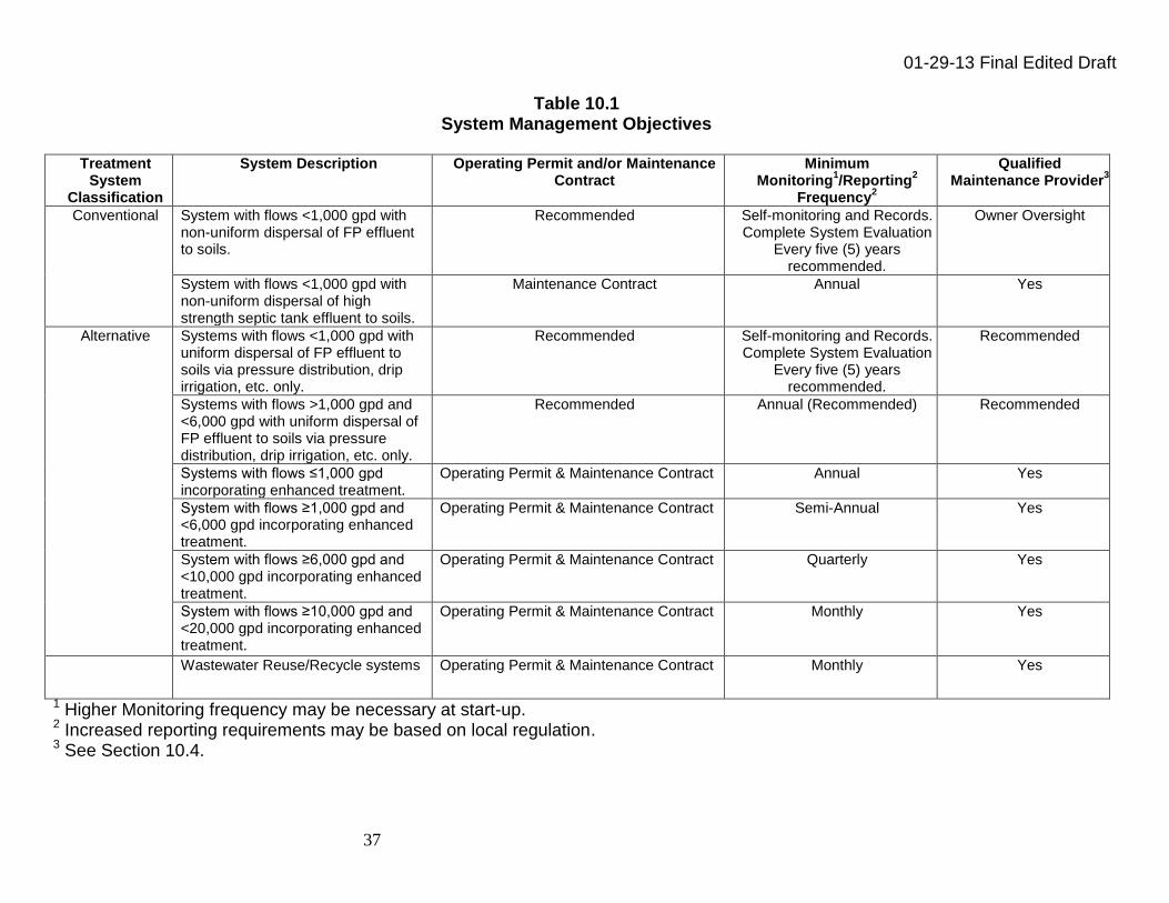
10.3 System Management Objectives Table 10.1 indicates the minimum system management and reporting objectives deemed appropriate based upon overall treatment system classification and design flow. These objectives can vary due to site specific concerns and/or treatment technology.
01-29-13 Final Edited Draft
37
Table 10.1 System Management Objectives
Treatment
System Classification
System Description Operating Permit and/or Maintenance Contract
Minimum Monitoring
1/Reporting
2
Frequency2
Qualified Maintenance Provider
3
Conventional System with flows <1,000 gpd with non-uniform dispersal of FP effluent to soils.
Recommended Self-monitoring and Records. Complete System Evaluation
Every five (5) years recommended.
Owner Oversight
System with flows <1,000 gpd with non-uniform dispersal of high strength septic tank effluent to soils.
Maintenance Contract Annual Yes
Alternative Systems with flows <1,000 gpd with uniform dispersal of FP effluent to soils via pressure distribution, drip irrigation, etc. only.
Recommended Self-monitoring and Records. Complete System Evaluation
Every five (5) years recommended.
Recommended
Systems with flows >1,000 gpd and <6,000 gpd with uniform dispersal of FP effluent to soils via pressure distribution, drip irrigation, etc. only.
Recommended Annual (Recommended) Recommended
Systems with flows ≤1,000 gpd incorporating enhanced treatment.
Operating Permit & Maintenance Contract Annual Yes
System with flows ≥1,000 gpd and <6,000 gpd incorporating enhanced treatment.
Operating Permit & Maintenance Contract Semi-Annual Yes
System with flows ≥6,000 gpd and <10,000 gpd incorporating enhanced treatment.
Operating Permit & Maintenance Contract Quarterly Yes
System with flows ≥10,000 gpd and <20,000 gpd incorporating enhanced treatment.
Operating Permit & Maintenance Contract Monthly Yes
Wastewater Reuse/Recycle systems Operating Permit & Maintenance Contract Monthly Yes
1 Higher Monitoring frequency may be necessary at start-up. 2 Increased reporting requirements may be based on local regulation. 3 See Section 10.4.
01-29-13 Final Edited Draft
38
10.4 Qualified Maintenance Providers The performance of operation and maintenance activities should only be undertaken by those qualified maintenance providers who possess adequate training and experience related to the specific treatment and dispersal system. It is the system owner’s responsibility to retain the services of such qualified maintenance provider to conduct/document necessary routine operation and maintenance activities. The DEQ may require the maintenance provider to become certified operators pursuant to statute and rules to demonstrate they are properly qualified to operate the facilities. Additionally, specific training and certification programs administered by proprietary equipment manufacturers or other third party organizations may be considered. The qualified maintenance provider shall be identified in the management plan.
Chapter 11 – Tank Design and Construction 11.1 General Septic tanks are often considered the single most important component for an on-site treatment system. Their ability to separate solids from the liquid, provide digestion of organic matter, and store solids result in a clarified liquid suitable for discharge from the tank for further treatment and/or soil dispersal. 11.2 Location Tanks shall be located: 1. Where they can be accessed easily for inspection and service, such as septage
removal and other service requirements.
2. Away from drainage swales or other depressions where water can collect. Non-sewage discharges (e.g. roof downspouts, water softeners, sump pumps, etc.) shall not be allowed near the tank area.
3. Where the minimum horizontal setback distance is obtained from buildings, property
boundaries, wells, water lines, etc., pursuant to Table 4.1.
4. Where there is minimal risk from vehicular traffic.
5. Above saturated soil whenever possible. 11.3 Tank Construction Tanks shall be: 1. Watertight (see Section 11.7). If tanks are installed in saturated soils, they shall be
designed and installed to protect against flotation when empty, per manufacture’s recommendations and information included by the system designer in the plan.
01-29-13 Final Edited Draft
39
2. Constructed of durable material that is resistant to excessive corrosion and
deformation from external soil and internal load pressures.
3. Structurally engineered for the depth of bury of the specific site. If vehicular traffic is a concern the tank shall be engineered for the intended load.
11.4 Tank Sizing and Geometry 11.4.1 Septic Tank Design Septic tanks shall have the following design: 1. Have a minimum size of 1,000 gallons, regardless of flow.
2. Have an effective liquid capacity sufficient to provide a minimum retention time of 2-
times the daily peak design flow if wastes are of typical domestic strength.
3. The length to width ratio of a single tank shall be no less than 2:1, however 3:1 is preferred. The greater ratio allows more opportunity for the flotation and settling processes to occur. The installation of multiple tanks may be accepted as a means to provide protection against short-circuiting of flow.
4. The water depth shall be no less than four (4) feet to provide an adequate zone for
the separation and stratification of raw waste materials into three zones within the tank commonly referred to as scum, sludge, and clear effluent zones.
5. When design flows are greater than 1,000 gpd, tank partitioning or multiple tanks
must be utilized. The first compartment or tank in a series must have a greater volume than any following compartment or tank. It is recommended that the first compartment have a capacity of one-half to two-thirds of the total volume required.
6. When the tank has compartments, flow between compartments can occur in the
baffle wall via piping located in the clear zone of the tank (mid-depth of tank). Adequate venting must be provided between compartments.
7. Have adequate tank volume prior to a proprietary treatment unit in compliance with
the manufacturer’s requirements.
8. Though not a recommended practice, if a tank has sewage inflow from a pumped source (e.g. lift station, ejection basin) the minimum retention time shall be 4 times the daily peak design flow.
11.4.2 Tank Considerations for High Strength Waste
One of the most common generators of high strength wastewater using on-site systems is food service establishments. The use of grease interceptor tanks is particularly important on systems serving food service establishments because the kitchen waste stream is often the largest portion of the organic waste load. For systems serving
01-29-13 Final Edited Draft
40
restaurants (or other food service establishments) under the criteria, the kitchen waste stream shall be plumbed to one or more grease interceptor tanks. Other waste streams, such as restrooms shall be plumbed directly to the septic tank(s) prior to combining the waste streams for other treatment or soil dispersal. For high strength waste: 1. Grease interceptor tanks shall have an effective liquid capacity sufficient to provide a
minimum retention time of three times the daily peak design flow.
2. Septic tank volume of three to four times the daily peak design flow should be provided. Increased tank volume alone may not reduce the waste strength to that comparable to domestic wastewater. However, more tank volume and/or multiple tanks may aid in the reduction of FOG.
11.5 Tank Inlets and Outlets 11.5.1 Tank inlet and outlet piping Tank inlet and outlet piping shall: 1. Locate the outlet pipe at minimum two (2) inches lower than the inlet pipe.
2. Attach the inlet and outlet pipe to the tank in a watertight manner using a flexible
gasket or boot.
3. Be constructed in a manner to allow proper venting of gasses. 11.5.2 Tank Inlet/Outlet Baffles and Sanitary Tees Tank inlet/outlet baffles and sanitary tees shall: 1. Consider an inlet baffle or tee or other method of energy dissipation when raw
sewage is being pumped into a tank to minimize disruption to the scum layer. The inlet baffle or tee should not extend as deep as does the outlet baffle or tee.
2. Be installed so that there is an air gap (for venting) between the top of the baffle and the underside of the tank lid.
3. Be installed to prevent the scum layer from exiting the tank. The outlet baffle or tee must extend into the clear zone of the tank, typically into the middle third of the liquid depth.
11.5.3 Effluent Filters
Effluent filters are effective in reducing the amount of suspended solids in effluent from the septic tank, providing an added measure of protection for the soil dispersal system. Effluent filters can also reduce the effects of water that surges through the septic tank
01-29-13 Final Edited Draft
41
as well as reduce or prevent damage to treatment components that may follow the septic tank. For new or existing septic tank installations, an effluent filter shall be used in lieu of the outlet baffle or tee in a single tank installation or the outlet of the last tank where multiple tanks are utilized. For existing septic tanks, installation of an effluent filter may be difficult or impossible. Whenever an effluent filter is required but cannot be physically installed in an existing septic tank other options shall be considered. Effluent filters shall be sized to handle the peak daily flow in accordance with manufacturer’s specifications. Consideration should be given to installation of a high water alarm to signal need for filter maintenance. 11.6 Access Risers and Lids Risers which terminate at or above final grade are required on all tank openings. Access risers and lids shall: 1. Have (at minimum) an opening over the inlet pipe/baffle and over the outlet baffle or
effluent filter. Additional openings shall be provided over any tank baffle wall that contains a baffled outlet port. Large tanks require additional openings to allow ample ability for inspection and/or to pump out tank contents. Opening size shall be a minimum of 24 inches. For deeper tanks or duplex pump installations a larger diameter riser may be warranted.
2. Be corrosion-resistant, watertight, and maintain structural integrity.
3. Be constructed of durable materials such as concrete, PVC, fiberglass, or high density polyethylene plastics.
4. Lids should be heavy enough to prevent access by children, or otherwise be secured
to prevent unauthorized access. If screws are used to secure the lid, stainless steel screws are required. Typical Phillips-head or slotted-head screws are not recommended. Screws with hex heads or other designs that require a special tool to remove them are recommended.
5. Have a secondary safety device installed in the riser to prevent an accidental fall into
the tank should the riser lid become unsecured.
6. Have a watertight connection between the riser and tank. Manufacturer’s installation requirements shall be followed.
7. Contain an adequate seal at the riser lid to prevent the escape of gases, water
infiltration, and intrusion by vermin.

01-29-13 Final Edited Draft
42
8. Minimize the potential of a riser lid flipping or dislodging when stepped upon. 11.7 Tank Installation Septic tank(s) shall be installed: 1. To rest on a uniform bearing surface. It is good practice to provide a level,
compacted granular base such as coarse sand or pea stone for the tank bedding. The underlying soils must be capable of bearing the weight of the tank and its contents when full. Soils with a high organic content or containing large boulders or massive rock edges are not suitable, unless properly prepared.
2. To meet all manufacturer’s specifications.
3. To have the tank excavation carefully planned to avoid over digging around the perimeter of the tank, except as necessary for the safety of workers. Unless it is done carefully, backfill operations can result in damage to the tank and pipe connections. The system installation contractor shall ensure excavations are conducted in a safe manner.
4. Using backfill material of a granular nature free of stones larger than three (3) inches
in diameter, debris, ice, or snow. Fill should be added in lifts no greater than 12 inches and each lift well compacted. For fine-textured native soils (e.g. silts, silt loams, clay loams, and/or clay) imported granular material should be used. This is a must where freeze and thaw cycles are common because the soil movement during such cycles can work tank joints open. When using plastic and fiberglass tanks, strict accordance to the manufacturer’s bedding and backfill requirements must be followed.
5. To protect against flotation when empty, tank manufacturers should be consulted for
appropriate anti-flotation methods or devices.
6. Using joint sealant conforming to ASTM C990 or equivalent, adhering to proper placement procedures and joining techniques for the sealant.
11.8 Tank Watertightness Testing Watertight, structurally sound tanks are essential to the performance of onsite wastewater systems. Wastewater that leaks out of a septic tank that is not watertight may not be adequately treated and can contaminate ground and surface waters. In addition, infiltration of the ground water into a leaky tank can hydraulically overload the downstream components of the treatment system. Furthermore, infiltration leading to tank mixing can result in a loss of the clear effluent zone discussed in section 11.4.1.3 thus allowing solids to carry over resulting in organic overloading. In order to ensure that a tank will adequately perform as intended, field testing of the tank for watertightness is essential. Septic tanks and pump-dose tanks shall be tested for watertightness using either a vacuum test or water test. a. Reference ASTM C-1227
01-29-13 Final Edited Draft
43
Chapter 12 – Pumps, Controls and Appurtenances 12.1 General Dosing and pressure distribution are standard practices for soil dispersal and many other secondary treatment processes. The primary method for dosing and distributing effluent is with a pump. Pumps are also utilized in conjunction with flow equalization facilities. Typical applications utilize submersible pumps designed specifically for either raw wastewater or effluent. Raw sewage applications will utilize non-clog submersible wastewater pumps designed specifically for this application. Effluent pumps are available in many models and styles, from single-stage centrifugal pumps to multistage turbine pumps. The advantages/disadvantages of choosing one pump type over the other must be considered by the system designer with pump selection based upon the intended application. Pump selection for the design pumping rate is made by determining the total dynamic pumping head (TDH) typically expressed in feet of water pressure. The system’s TDH calculation, pump rate (gpm) basis of design and manufacturer’s pump curve must be included with the plan submittal for review and approval. 12.2 Raw Sewage Pumping Raw sewage pumps are normally used in lift stations in conjunction with gravity collection systems before treatment works to move raw, unsettled wastewater. Sewage pumps including grinder pumps are also used to eject raw wastewater from a lower elevation such as a basement. In general, the practice of pumping directly into septic tanks is discouraged. The use of grinder pumps for raw sewage ahead of septic tanks should be avoided. Grinding sewage into a slurry of small particles has the potential to affect normal settling and digestive processes. If pumping of raw sewage cannot be avoided, additional design measures must be included to mitigate negative effects, primarily surging and turbulence, on overall treatment system performance. Options that may be considered include: 1. Pumping to gravity sewer some minimum distance upstream of the septic tank
instead of directly into the septic tank.
2. Install an inlet baffle in the septic tank to deflect the inlet discharge.
3. Install more septic tank capacity or a surge tank prior to the septic tank.
4. Install multiple septic tanks in series or compartmented septic tanks. 12.3 Time Dosing Current and best practice recognizes the importance and benefit of reducing instantaneous hydraulic and organic loading. Small doses followed by resting periods
01-29-13 Final Edited Draft
44
spread evenly throughout the day enhances microbial activity, improves treatment, and system longevity. Control of pumping units by means of programmable timers is preferred. Time dosing in conjunction with pressure distribution is required for all soil dispersal systems over 1,000 gpd. Time dosing is strongly encouraged for all systems whenever a pump is used to dose a soil dispersal system. Time dosing provides a means of monitoring the treatment system and can also provide a means for detection of leaking plumbing fixtures (e.g. leaking toilet), infiltration, and inflow. Should the volume within the dosing tank exceed the design surge volume, a high level alarm will activate. 12.4 Demand Dosing Discharge of wastewater or effluent with demand dosing provides for delivery of hydraulic and organic loads which more closely match diurnal flow patterns. Demand dosing delivers flows to downstream components in predetermined amounts only controlled by the established dosing tank’s liquid level control settings. While acceptable, demand dosing is not encouraged in situations where dosing is required. Demand dosing should only be considered when flows are <1,000 gpd. Unless flows are carefully monitored, demand dosing will not provide protection of the system from leaking fixtures and infiltration, unlike time dosing. 12.5 Distribution Valves Pump sizes may be kept smaller, even for large systems, by dividing the distribution system into “zones” with the use of hydraulic sequencing valves. Such valves permit a small portion of the soil dispersal system to be dosed at any one time, while the remaining zones rest. Like an underground irrigation system, the valve rotates from zone to zone during pump cycles. Small doses with intermittent resting can optimize treatment performance. Other advantages include the use of smaller pumps, smaller diameter pipe network, and more uniform effluent distribution on slopes. The system designer must be familiar with the proper installation and operation of such valves and show installation details and specifications on construction plans. A description of the necessary operation and maintenance of these components needs to be included in the O & M Manual for the system. 12.6 Number of Pumping Units Wherever continuous service without interruption is necessary or desired, pumping installations must include a minimum of two alternating pumping units each equipped to discharge at the design flow rate. The requirement for two pumping units may be waived for systems with flows <1,000 gpd and where: 1. Wastewater flow can be interrupted temporarily without causing sewage to backup
into facility and/or onto ground surface while repairs are made;
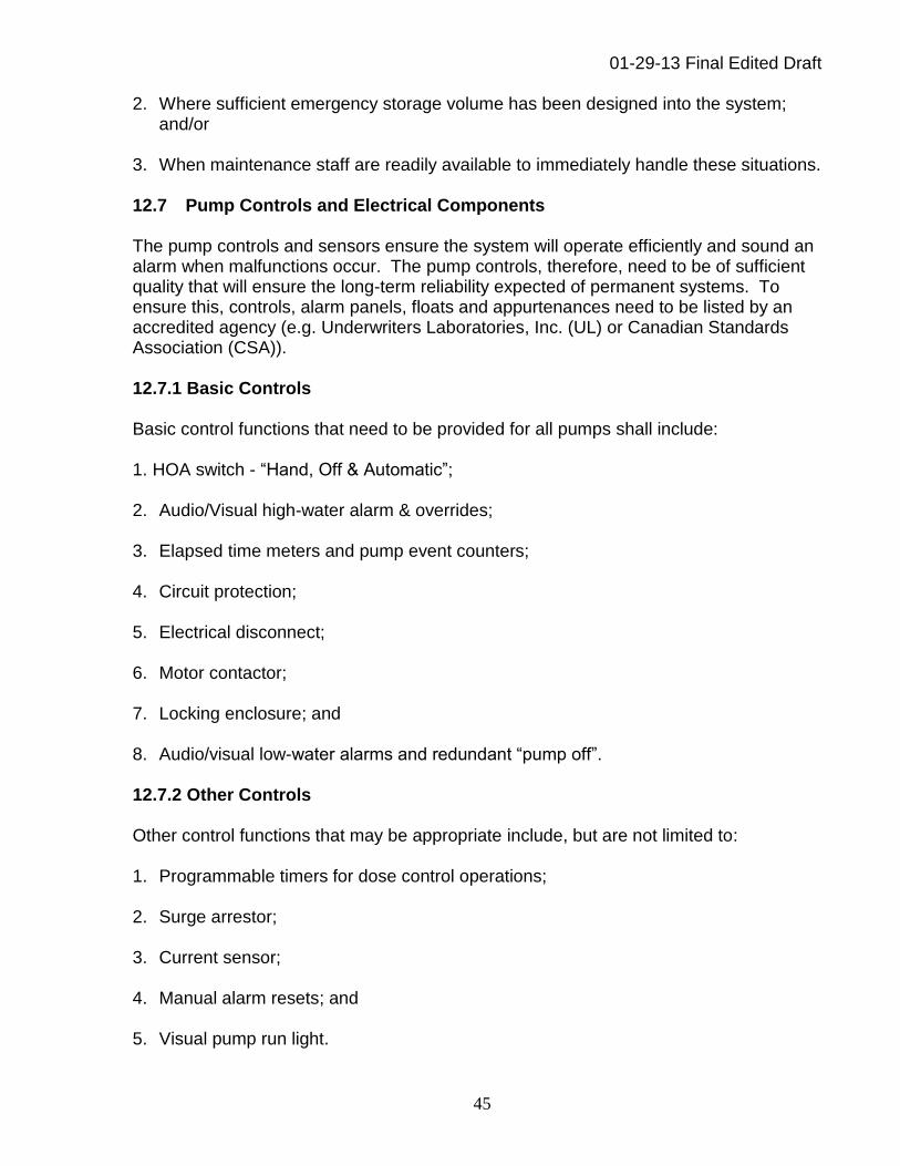
01-29-13 Final Edited Draft
45
2. Where sufficient emergency storage volume has been designed into the system; and/or
3. When maintenance staff are readily available to immediately handle these situations. 12.7 Pump Controls and Electrical Components The pump controls and sensors ensure the system will operate efficiently and sound an alarm when malfunctions occur. The pump controls, therefore, need to be of sufficient quality that will ensure the long-term reliability expected of permanent systems. To ensure this, controls, alarm panels, floats and appurtenances need to be listed by an accredited agency (e.g. Underwriters Laboratories, Inc. (UL) or Canadian Standards Association (CSA)). 12.7.1 Basic Controls Basic control functions that need to be provided for all pumps shall include: 1. HOA switch - “Hand, Off & Automatic”;
2. Audio/Visual high-water alarm & overrides;
3. Elapsed time meters and pump event counters;
4. Circuit protection;
5. Electrical disconnect;
6. Motor contactor;
7. Locking enclosure; and
8. Audio/visual low-water alarms and redundant “pump off”. 12.7.2 Other Controls Other control functions that may be appropriate include, but are not limited to: 1. Programmable timers for dose control operations;
2. Surge arrestor;
3. Current sensor;
4. Manual alarm resets; and
5. Visual pump run light.
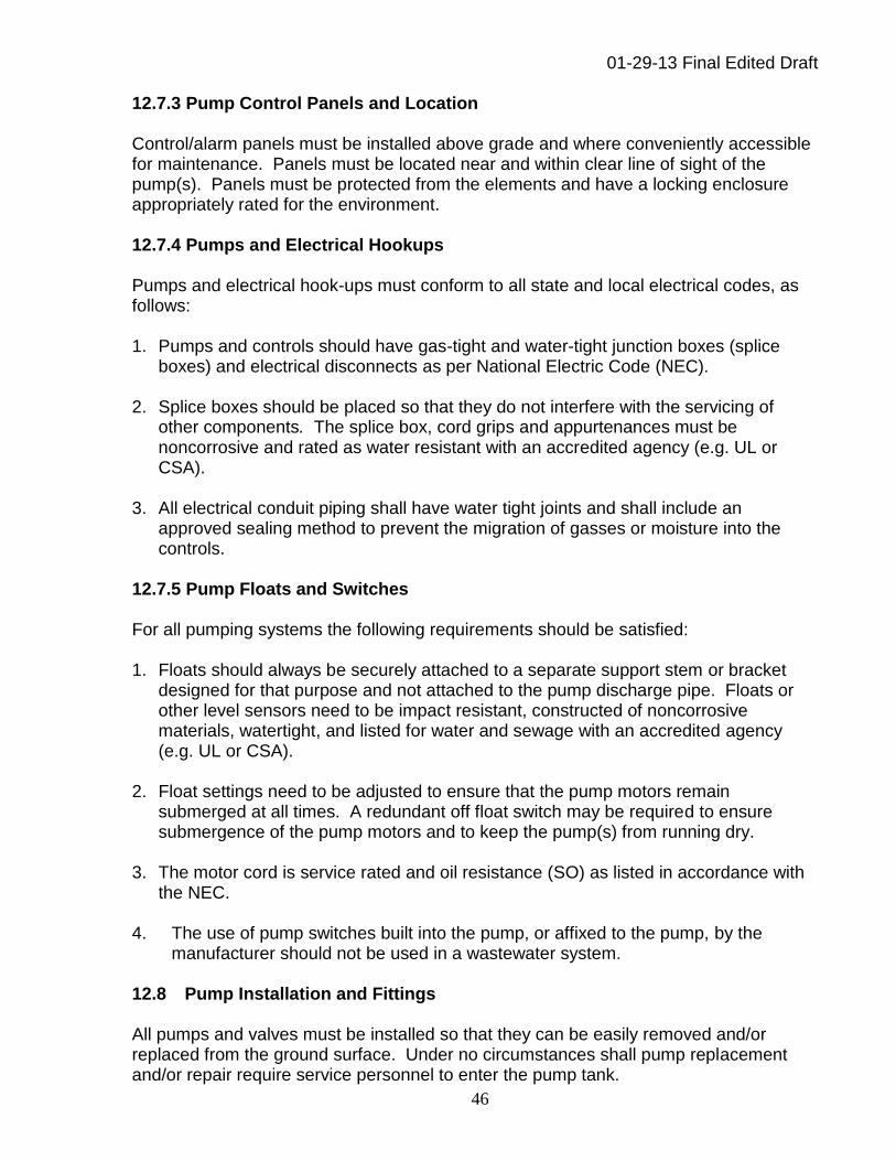
01-29-13 Final Edited Draft
46
12.7.3 Pump Control Panels and Location Control/alarm panels must be installed above grade and where conveniently accessible for maintenance. Panels must be located near and within clear line of sight of the pump(s). Panels must be protected from the elements and have a locking enclosure appropriately rated for the environment. 12.7.4 Pumps and Electrical Hookups Pumps and electrical hook-ups must conform to all state and local electrical codes, as follows: 1. Pumps and controls should have gas-tight and water-tight junction boxes (splice
boxes) and electrical disconnects as per National Electric Code (NEC).
2. Splice boxes should be placed so that they do not interfere with the servicing of other components. The splice box, cord grips and appurtenances must be noncorrosive and rated as water resistant with an accredited agency (e.g. UL or CSA).
3. All electrical conduit piping shall have water tight joints and shall include an
approved sealing method to prevent the migration of gasses or moisture into the controls.
12.7.5 Pump Floats and Switches For all pumping systems the following requirements should be satisfied: 1. Floats should always be securely attached to a separate support stem or bracket
designed for that purpose and not attached to the pump discharge pipe. Floats or other level sensors need to be impact resistant, constructed of noncorrosive materials, watertight, and listed for water and sewage with an accredited agency (e.g. UL or CSA).
2. Float settings need to be adjusted to ensure that the pump motors remain
submerged at all times. A redundant off float switch may be required to ensure submergence of the pump motors and to keep the pump(s) from running dry.
3. The motor cord is service rated and oil resistance (SO) as listed in accordance with
the NEC. 4. The use of pump switches built into the pump, or affixed to the pump, by the
manufacturer should not be used in a wastewater system. 12.8 Pump Installation and Fittings All pumps and valves must be installed so that they can be easily removed and/or replaced from the ground surface. Under no circumstances shall pump replacement and/or repair require service personnel to enter the pump tank.

01-29-13 Final Edited Draft
47
Pumps must be fitted with unions, valves, and electrical connections deemed necessary for easy pump removal and repair. Lift chains or rope must be of size and strength to allow safe pump removal. Lift chain shall be stainless steel or other noncorrosive material. Lift rope must be of material that will not be subject to deterioration in a wastewater environment. All effluent pumps must be suitably protected against clogging, normally by approved septic tank outlet filters or by screened pump vaults. Pump vaults provide the added benefit of suspending the pump off the bottom of the pump tank, allowing room on the bottom for biosolids to accumulate without being picked up by the pump and discharged to the soil dispersal system. Most vault designs also hold floating scum in the tank as well. Pump vaults or effluent screens or filters must be well maintained as part of routine O&M. If any portion of the pump fittings or transport line is at a higher elevation than the soil dispersal system, the system must be equipped with an air vacuum release valve or other suitable device to avoid siphoning. The force main should have a weep hole inside the pump chamber, be buried below the frost line, or have additional measures to address freezing concerns. If a weep hole is used to allow drainback of effluent remaining in the transport line at the end of a pumping event, the system designer must factor the volume of the transport line into the dosing volume design. This is also necessary when a check valve is omitted in the pump discharge piping. It may also be necessary to consider the quantity of discharge through the weep hole when determining pump run times. All of this becomes more important as the length and diameter of the transport line increases. 12.9 Effluent Pump Selection Effluent pumps are generally one of two types - submersible centrifugal pumps or multistage high-head turbine pumps. Each type of pump is better suited for certain types of applications than the other. The difference is typically in the TDH against which the pump is capable of operating. Turbine pumps will generally pump against much higher TDH than centrifugal pumps which is advantageous when the system may experience increased back pressure during its operation (e.g. the clogging of orifices in a pressure distribution network). In general, multistage high-head turbine pumps produce less flow, but more head (steep pump curve). In contrast, single stage centrifugal pumps generally produce more flow with less head (flatter pump curve). The system designer needs to refer to the specific manufacturer’s pump curve for pump selection and performance. Submersible turbine pumps may also require a draft tube sometimes called a flow inducer to route flow past the pump motor for cooling. Other specific installation requirements may also be recommended or required by the pump manufacturer so as not to void the warranty.
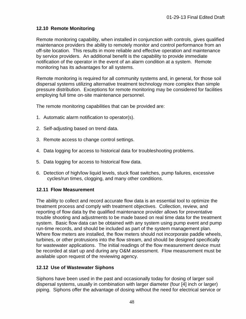
01-29-13 Final Edited Draft
48
12.10 Remote Monitoring Remote monitoring capability, when installed in conjunction with controls, gives qualified maintenance providers the ability to remotely monitor and control performance from an off-site location. This results in more reliable and effective operation and maintenance by service providers. An additional benefit is the capability to provide immediate notification of the operator in the event of an alarm condition at a system. Remote monitoring has its advantages for all systems. Remote monitoring is required for all community systems and, in general, for those soil dispersal systems utilizing alternative treatment technology more complex than simple pressure distribution. Exceptions for remote monitoring may be considered for facilities employing full time on-site maintenance personnel. The remote monitoring capabilities that can be provided are: 1. Automatic alarm notification to operator(s).
2. Self-adjusting based on trend data.
3. Remote access to change control settings.
4. Data logging for access to historical data for troubleshooting problems.
5. Data logging for access to historical flow data.
6. Detection of high/low liquid levels, stuck float switches, pump failures, excessive
cycles/run times, clogging, and many other conditions. 12.11 Flow Measurement The ability to collect and record accurate flow data is an essential tool to optimize the treatment process and comply with treatment objectives. Collection, review, and reporting of flow data by the qualified maintenance provider allows for preventative trouble shooting and adjustments to be made based on real time data for the treatment system. Basic flow data can be obtained with any system using pump event and pump run-time records, and should be included as part of the system management plan. Where flow meters are installed, the flow meters should not incorporate paddle wheels, turbines, or other protrusions into the flow stream, and should be designed specifically for wastewater applications. The initial readings of the flow measurement device must be recorded at start up and during any O&M assessment. Flow measurement must be available upon request of the reviewing agency. 12.12 Use of Wastewater Siphons Siphons have been used in the past and occasionally today for dosing of larger soil dispersal systems, usually in combination with larger diameter (four [4] inch or larger) piping. Siphons offer the advantage of dosing without the need for electrical service or

01-29-13 Final Edited Draft
49
pumps. However, siphons are not effective when trying to use small diameter pipes and orifices for uniform pressure distribution for the following reasons: 1. Siphons rely upon gravity flow to work properly, and in many cases, site elevations
do not allow sufficient head to achieve an adequate pressure in soil dispersal distribution piping.
2. Siphons do not have the ability to generate higher pressures in the event of orifice
clogging.
3. Siphons cannot generate the required pressure necessary for routine lateral flushing, a necessary practice for pressure distribution system maintenance.
Therefore, siphons are discouraged for use in connection with pressure distribution systems and/or small diameter orifices. If approved, a dosing event counter shall be incorporated in the design so the qualified maintenance provider can monitor whether the siphon is working properly. The system’s management plan shall provide for the regular inspection of the siphon operation.
Chapter 13 – Flow Equalization 13.1 Introduction and Application Flow equalization is the process of reducing the variability of the influent flow and waste strength to a system component over time. This is accomplished by storing peak flows and metering their release at a predetermined rate to approximate the average daily flow or, in some cases, the average over several days. In general, both conventional and alternative treatment technologies are designed to work within a range of hydraulic and organic loads. Extreme variations in flow rates and wastewater concentrations can compromise the treatment processes. All systems must be designed to handle periods of high flow or high waste concentrations and still be able to provide sufficient biochemical treatment to the discharged wastewater. Flow equalization can dampen these variations, allowing for a constant or near constant flow and waste strength delivery to a treatment component and/or the soil dispersal system. Equalizing flow just prior to discharge to the final dispersal system may also be considered to allow for design and construction of the dispersal component based upon an equalized flow rate. Flow equalization is useful and may be considered for the following types of facilities: 1. Banquet/rental halls;
2. Churches;
3. Festivals, flea markets;
4. Offices;

01-29-13 Final Edited Draft
50
5. Schools;
6. Stadiums; and/or
7. Or other facilities where equalization of flow or waste strength patterns would optimize the treatment system performance.
13.2 Flow Equalization Terminology For the purposes of clarification: 1. Equalized Daily Flow – The total volume of wastewater generated by flow events at
the facility during the flow equalization cycle divided by the number of days in the cycle.
2. Flow Equalization Cycle – The time period in which wastewater will be stored and
dosed. Example 1-day cycle, 7-day cycle, 14-day cycle, etc.
3. Flow Event – An event in the flow equalization cycle in which wastewater will be generated. Examples: church service, sporting event, day of operation, etc.
4. Flow Mass Balance – an account of the amount of stored effluent in the equalization
tank which is derived from the incoming flow, residual storage, and the outgoing flow. The flow mass balance identifies the flow events, the amount of wastewater generated, the amount of wastewater dosed, and the residual amount of effluent left in the dosing tank at any particular time. At the end of the flow equalization cycle, the sum of the amount dosed should equal the sum of the incoming flow.
5. Equalization Storage Volume – The calculated maximum residual storage volume
over the equalization cycle; plus a 20 percent or greater factor of safety. The system designer shall choose a factor of safety and show in his/her calculations the factor used in sizing the system.
13.3 Placement of Flow Equalization The placement of flow equalization can occur at various locations in the treatment scheme, depending upon the design of treatment works. If septic tanks are the means of primary treatment, then the equalization volume is normally located downstream of a septic tank with capacity as required by Chapter 11. The actual location of the storage will be a decision by the system designer based upon a consideration of site conditions, treatment system design, and overall cost effectiveness. A fluctuating water level in the septic tanks used for treatment and solids storage should only be considered in exceptional cases, and only for systems generating less than 1,000 gpd. When flow equalization is used, the downstream treatment components following storage would then be designed based upon the equalized daily flow and the soil loading rates in Table 4.2.

01-29-13 Final Edited Draft
51
13.4 Establishing Equalization Storage Volume Flow variability typically occur monthly, daily, hourly, or due to special events. For other facilities establishing equalization volume requires an evaluation of flow patterns over the equalization cycle. When possible, actual recorded flow data should be utilized. Otherwise, methods that reliably estimate expected daily flows and usage patterns may be considered. The system designer will be responsible for providing a mass balance of flow over the equalization cycle in support of the system design. The mass balance shall estimate the specific daily flow into storage, the controlled flow out of storage, and the storage required at any time during the cycle. Plan details and specifications shall then reflect how this storage is to be provided, with specific dimensions, elevations, and tank volumes.
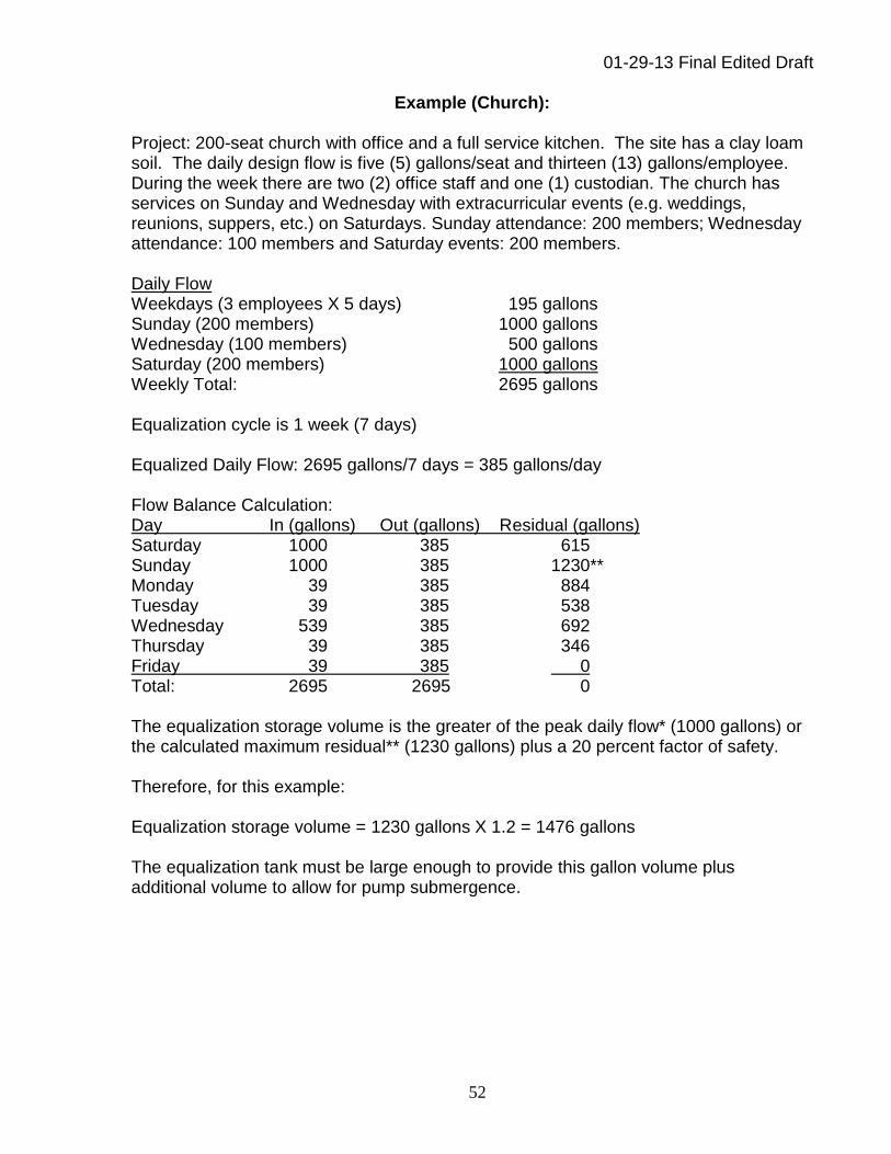
01-29-13 Final Edited Draft
52
Example (Church): Project: 200-seat church with office and a full service kitchen. The site has a clay loam soil. The daily design flow is five (5) gallons/seat and thirteen (13) gallons/employee. During the week there are two (2) office staff and one (1) custodian. The church has services on Sunday and Wednesday with extracurricular events (e.g. weddings, reunions, suppers, etc.) on Saturdays. Sunday attendance: 200 members; Wednesday attendance: 100 members and Saturday events: 200 members. Daily Flow Weekdays (3 employees X 5 days) 195 gallons Sunday (200 members) 1000 gallons Wednesday (100 members) 500 gallons Saturday (200 members) 1000 gallons Weekly Total: 2695 gallons Equalization cycle is 1 week (7 days) Equalized Daily Flow: 2695 gallons/7 days = 385 gallons/day Flow Balance Calculation: Day In (gallons) Out (gallons) Residual (gallons) Saturday 1000 385 615 Sunday 1000 385 1230** Monday 39 385 884 Tuesday 39 385 538 Wednesday 539 385 692 Thursday 39 385 346 Friday 39 385 0 Total: 2695 2695 0 The equalization storage volume is the greater of the peak daily flow* (1000 gallons) or the calculated maximum residual** (1230 gallons) plus a 20 percent factor of safety. Therefore, for this example: Equalization storage volume = 1230 gallons X 1.2 = 1476 gallons The equalization tank must be large enough to provide this gallon volume plus additional volume to allow for pump submergence.
01-29-13 Final Edited Draft
53
13.6 Equalization Pump Control Pump control shall be accomplished by means of programmable timers with settings to discharge the equalized daily flow. Controls shall include a high water alarm to be signaled at or above the equalization volume level in the tank. A low level alarm/redundant off capability shall also be provided. 13.7 Distribution of Final Effluent to Soil Dispersal Pressure distribution shall be utilized where design flow exceeds 1000 gpd.
Chapter 14 – Soil Dispersal System Design and Construction 14.1 Introduction The design and construction of the soil dispersal component system is a key element contributing to successful operation. A variety of design options are detailed below for the system designer’s consideration. It is important for the system designer to utilize distribution components and methodologies that are appropriate for the strength and volume of wastewater produced by a facility. The objective in any soil dispersal system design is to maintain a consistent aerobic soil environment. The utilization of pressure distribution providing controlled, equally distributed doses of effluent is preferred in most cases. This provides for a well-balanced aerobic ecosystem to flourish within the soil environment offering better long-term treatment results and overall system longevity.
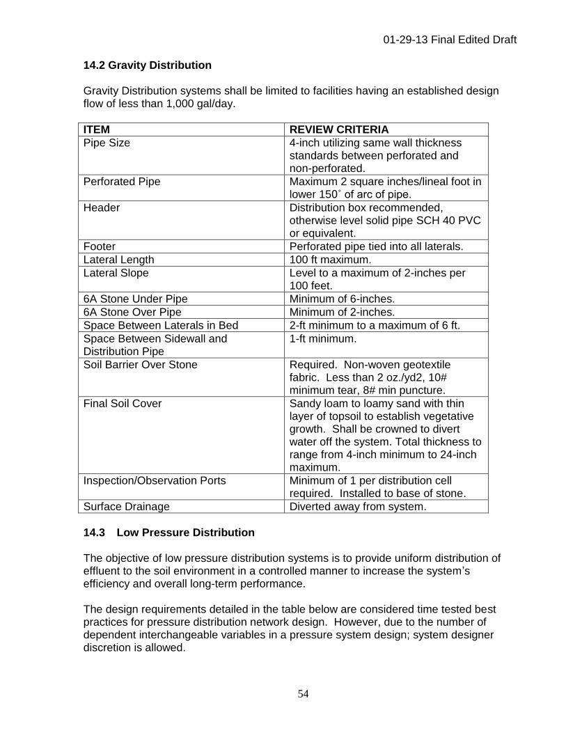
01-29-13 Final Edited Draft
54
14.2 Gravity Distribution Gravity Distribution systems shall be limited to facilities having an established design flow of less than 1,000 gal/day.
ITEM REVIEW CRITERIA
Pipe Size 4-inch utilizing same wall thickness standards between perforated and non-perforated.
Perforated Pipe Maximum 2 square inches/lineal foot in lower 150˚ of arc of pipe.
Header Distribution box recommended, otherwise level solid pipe SCH 40 PVC or equivalent.
Footer Perforated pipe tied into all laterals.
Lateral Length 100 ft maximum.
Lateral Slope Level to a maximum of 2-inches per 100 feet.
6A Stone Under Pipe Minimum of 6-inches.
6A Stone Over Pipe Minimum of 2-inches.
Space Between Laterals in Bed 2-ft minimum to a maximum of 6 ft.
Space Between Sidewall and Distribution Pipe
1-ft minimum.
Soil Barrier Over Stone Required. Non-woven geotextile fabric. Less than 2 oz./yd2, 10# minimum tear, 8# min puncture.
Final Soil Cover Sandy loam to loamy sand with thin layer of topsoil to establish vegetative growth. Shall be crowned to divert water off the system. Total thickness to range from 4-inch minimum to 24-inch maximum.
Inspection/Observation Ports Minimum of 1 per distribution cell required. Installed to base of stone.
Surface Drainage Diverted away from system.
14.3 Low Pressure Distribution The objective of low pressure distribution systems is to provide uniform distribution of effluent to the soil environment in a controlled manner to increase the system’s efficiency and overall long-term performance. The design requirements detailed in the table below are considered time tested best practices for pressure distribution network design. However, due to the number of dependent interchangeable variables in a pressure system design; system designer discretion is allowed.
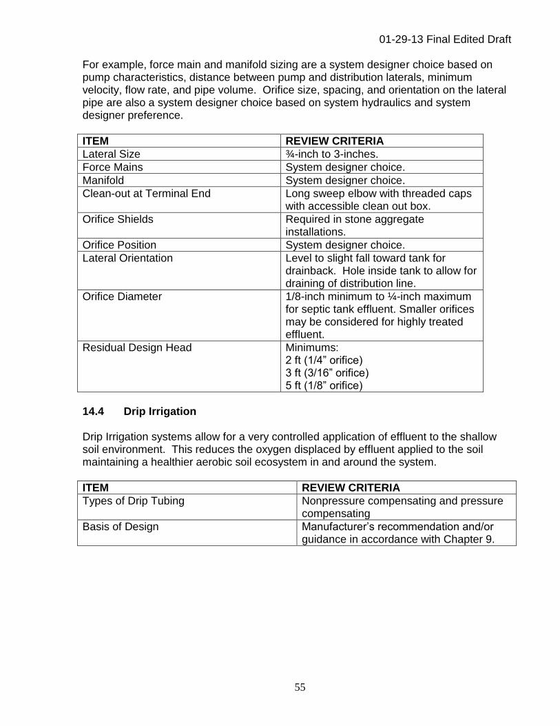
01-29-13 Final Edited Draft
55
For example, force main and manifold sizing are a system designer choice based on pump characteristics, distance between pump and distribution laterals, minimum velocity, flow rate, and pipe volume. Orifice size, spacing, and orientation on the lateral pipe are also a system designer choice based on system hydraulics and system designer preference.
ITEM REVIEW CRITERIA
Lateral Size ¾-inch to 3-inches.
Force Mains System designer choice.
Manifold System designer choice.
Clean-out at Terminal End Long sweep elbow with threaded caps with accessible clean out box.
Orifice Shields Required in stone aggregate installations.
Orifice Position System designer choice.
Lateral Orientation Level to slight fall toward tank for drainback. Hole inside tank to allow for draining of distribution line.
Orifice Diameter 1/8-inch minimum to ¼-inch maximum for septic tank effluent. Smaller orifices may be considered for highly treated effluent.
Residual Design Head Minimums: 2 ft (1/4” orifice) 3 ft (3/16” orifice) 5 ft (1/8” orifice)
14.4 Drip Irrigation Drip Irrigation systems allow for a very controlled application of effluent to the shallow soil environment. This reduces the oxygen displaced by effluent applied to the soil maintaining a healthier aerobic soil ecosystem in and around the system.
ITEM REVIEW CRITERIA
Types of Drip Tubing Nonpressure compensating and pressure compensating
Basis of Design Manufacturer’s recommendation and/or guidance in accordance with Chapter 9.
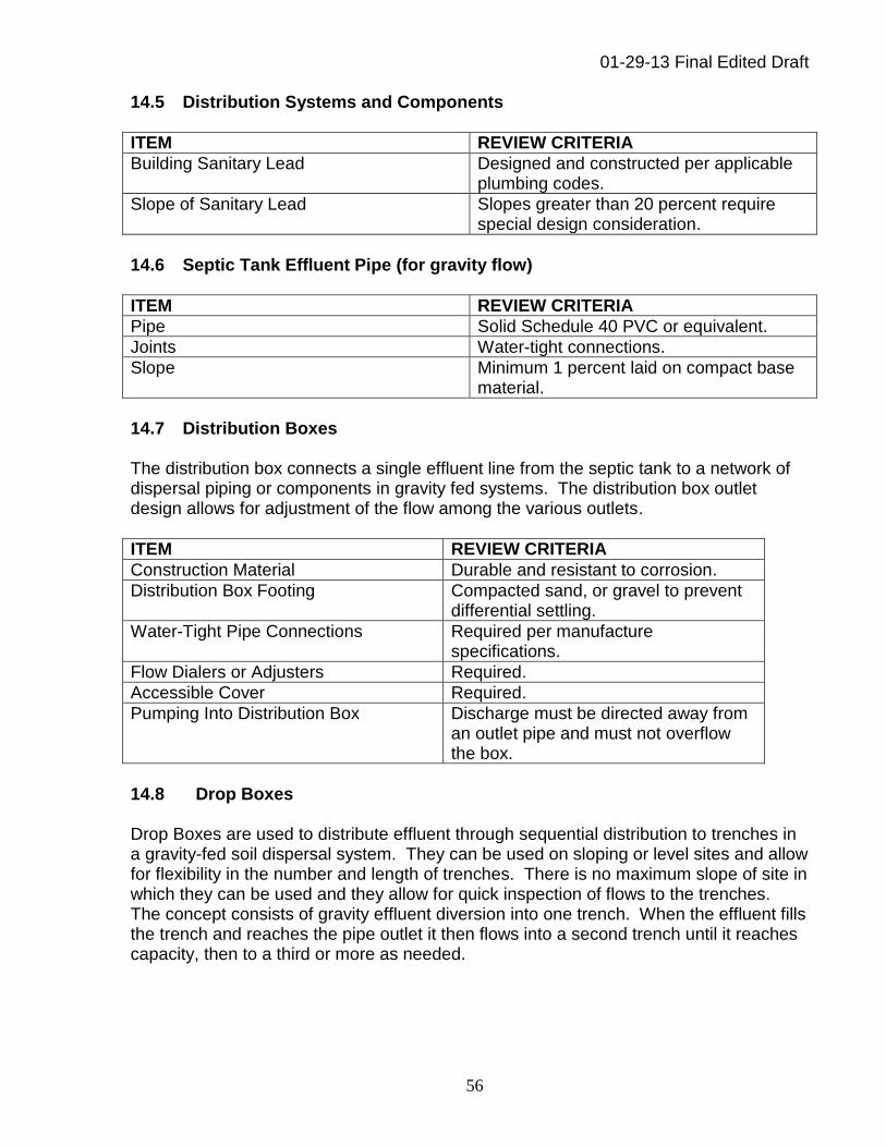
01-29-13 Final Edited Draft
56
14.5 Distribution Systems and Components
ITEM REVIEW CRITERIA
Building Sanitary Lead Designed and constructed per applicable plumbing codes.
Slope of Sanitary Lead Slopes greater than 20 percent require special design consideration.
14.6 Septic Tank Effluent Pipe (for gravity flow)
ITEM REVIEW CRITERIA
Pipe Solid Schedule 40 PVC or equivalent.
Joints Water-tight connections.
Slope Minimum 1 percent laid on compact base material.
14.7 Distribution Boxes The distribution box connects a single effluent line from the septic tank to a network of dispersal piping or components in gravity fed systems. The distribution box outlet design allows for adjustment of the flow among the various outlets.
ITEM REVIEW CRITERIA
Construction Material Durable and resistant to corrosion.
Distribution Box Footing Compacted sand, or gravel to prevent differential settling.
Water-Tight Pipe Connections Required per manufacture specifications.
Flow Dialers or Adjusters Required.
Accessible Cover Required.
Pumping Into Distribution Box Discharge must be directed away from an outlet pipe and must not overflow the box.
14.8 Drop Boxes Drop Boxes are used to distribute effluent through sequential distribution to trenches in a gravity-fed soil dispersal system. They can be used on sloping or level sites and allow for flexibility in the number and length of trenches. There is no maximum slope of site in which they can be used and they allow for quick inspection of flows to the trenches. The concept consists of gravity effluent diversion into one trench. When the effluent fills the trench and reaches the pipe outlet it then flows into a second trench until it reaches capacity, then to a third or more as needed.
01-29-13 Final Edited Draft
57
ITEM REVIEW CRITERIA
Construction Material Durable and resistant to corrosion.
Footing Compacted sand, or gravel to prevent differential settling.
Water-tight Pipe Connections Required.
Internal Flow Control Mechanism Required.
Accessible Cover Required.
Connecting Piping Non-perforated pipe.
Back fill around connecting piping Compacted native soil only – no stone allowed.
14.9 Mechanical Distribution Valves The use of distribution valves allow a system designer to break a large dispersal field into smaller zones, thus minimizing pipe size and pump size resulting energy conservation. Furthermore, the valves can help optimize treatment by allowing a zone to receive a small volume dose while the remaining zones can “rest” between dose cycles. Valves can also be utilized to provide equal distribution of effluent to trenches located on slopes.
ITEM REVIEW CRITERIA
Elevation Highest point of dispersal field for proper sequencing of valve.
Valve Accessibility and Freeze Protection Required - Must be accessible and placed in an insulated housing to prevent freezing.
Force Main to the Valve Should remain full to increase operational reliability of the valve.
Pump Selection Must consider frictional losses through valve.
14.10 Nonaggregate Systems Nonaggregate systems include chamber systems and man-made material (e.g. tire chips, glass, etc.). Systems of this category can offer a good design solution for a variety of applications. Specific consideration may be given to non-aggregate systems when clean stone aggregate is not available; at sites with limited equipment access; or where sensitive soils are present that will be compacted or smeared by the use of heavy equipment to carry in the materials. The state may periodically issue recommendations/advisories on the use of non-aggregate systems and be made available on the department’s website.
01-29-13 Final Edited Draft
58
ITEM REVIEW CRITERIA
Sizing Minimum bottom area square footage same as equivalent stone aggregate system.
Installations Installed per manufacturer’s specifications and in accordance with applicable. guidance (see Chapter 1)
14.11 Final Cover and Grading The total depth of the final cover should be minimized to promote aerobic conditions. A minimum of 4-inches and a maximum of 24-inches of suitable earth cover shall be placed over the soil dispersal system. Suitable earth cover means a permeable soil that will allow aeration and that will support the growth of grass. Loamy sand soils are preferred. Loam or heavier soil textures shall be prohibited. The surface must be graded such that water will not pond on the system. Vegetative cover over the soil dispersal area should be established as soon as possible after construction in order to prevent soil erosion and promote aerobic conditions within the treatment area.
01-29-13 Final Edited Draft
59
Definitions Above-Grade – means a soil dispersal system where the entire infiltrative surface is located above natural ground surface elevation. Agency – means the DEQ, a city health department, a county health department, or a district health department, whichever has jurisdiction. Alternative System – means a treatment and soil dispersal system which is not a conventional system and provides for an equivalent or better degree of protection for public health and the environment than a conventional system. Aquifer – means a subsurface water-bearing geologic material that transmits water in sufficient quantities to supply a well. At-Grade – refers to a soil dispersal system where the infiltrative surface is located at the natural ground surface elevation. Authorized LHD – a city health department, county health department, or district health department whom has been granted authority to administer these criteria by the DEQ. Bedrock – means consolidated and continuous geologic material, such as limestone, dolomite, shale, sandstone, basalt, or granite. Below-Grade – refers to a soil dispersal system where the infiltrative surface is below the natural ground surface elevation. BOD5 – means the quantitative measure of the amount of oxygen consumed by bacteria while stabilizing, digesting, or treating biodegradable organic matter in a sample under aerobic conditions over a five-day incubation period; expressed in milligrams per liter (mg/L). Certified Operator – means a municipal wastewater operator certified under Part 41, Sewerage Systems, of the NREPA, and/or an industrial/commercial wastewater operator certified under Part 31, Industrial and Commercial Waste Treatment Facilities, of the NREPA. Community On-Site Wastewater System – means a sewerage system that collects, conveys, transports, treats, or otherwise handles sanitary sewage for more than one individually owned family unit or dwelling or more than one individually owned business. Competent Professional – means an individual who can demonstrate the knowledge, skills, and abilities necessary to perform specific functions under the criteria. Competent Soil Evaluator – means an individual who can demonstrate the knowledge, skills, and abilities necessary to conduct and report soil evaluations based upon the USDA classification system pursuant to these criteria.
01-29-13 Final Edited Draft
60
Confining Layer – means geologic material which has a low hydraulic conductivity which impedes or prevents vertical groundwater movement. Confining Layers of Sufficient Areal Extent – means the presence of contiguous/continuous confining layers in an area proposed for soil dispersal sufficient to protect a drinking water aquifer. Conventional System – means an on-site wastewater treatment and soil dispersal system that contains a watertight septic tank with nonuniform distribution of effluent to subsurface soil trenches or an absorption bed. DEQ – means the Michigan Department of Environmental Quality. Direct Hydraulic Connection – means a condition where wastewater effluent is dispersed into permeable soils that provide a direct conduit to an aquifer that is used or intended to be used for drinking water purposes. Dispersal System – means a system used for the subsurface distribution of wastewater effluent to soil. Disturbed Soil – means a soil layer that has been changed from its natural condition by excavation or other activities such as soil compaction, removal, and smearing that would be expected to affect the function of the soil dispersal system. Traditional planting and tilling activities from historic agricultural practices are not considered disturbed soil. Domestic Equivalent Wastewater – means wastewater that falls outside the definition of sanitary sewage but which has similar wastewater characteristics and is amenable to on-site wastewater treatment and subsurface soil dispersal. Drains designed to lower the water table – means any tile installed to reduce the elevation of groundwater elevation inclusive of farming tiles. Enhanced Treatment – means the biological and physical/chemical treatment of filtered septic tank effluent to reduce the amount of biochemical oxygen demand (BOD5), total suspended solids (TSS) or nutrients including phosphorous and nitrogen prior to discharge to a soil dispersal system. Established 100-Year Floodplain – means the area of land adjoining surface water which will be inundated by a 100-year flood. ETV – means the Environmental Technology Verification Program instituted by the U.S. EPA to verify the performance characteristics of commercial-ready environmental technologies. Existing Water Well Records – means the available water well construction information (private residential, public, irrigation, industrial, and test wells) in the vicinity of the area being evaluated for on-site wastewater treatment and soil dispersal.

01-29-13 Final Edited Draft
61
Facility – means a structure generating wastewater that discharges to an on-site treatment and soil dispersal system. It does not refer to the definition under Act 201, Environmental Remediation, of the NREPA. FOG – means fats, oils and greases, the constituents of sewage typically originating from foodstuffs (animal fats or vegetable oils) or consisting of compounds of alcohol or glycerol with fatty acids (soaps and lotions), typically measured in milligrams per Liter (mg/L). Force Main/Transport Line – means a segment of pipe which conveys wastewater effluent from a pump reservoir to the soil dispersal piping network. Fragipan – means a loamy, brittle subsurface horizon low in porosity and content of organic matter and low to moderate in clay but high in silt or very fine sand. A fragipan appears cemented and restricts roots. When dry, it is hard or very hard and has a higher bulk density than the horizon or horizons above. When moist, it tends to rupture suddenly under pressure rather than to deform slowly. Grease Interceptor Tank – means a relatively large watertight device similar to a septic tank located outside a facility that generates commercial food service wastewater and is designed to intercept, congeal, and retain or remove fats, oils, and grease (FOGs). Groundwater – means the water in the ground that is in the zone of saturation. Groundwater Flow – means the directional movement of groundwater travelling through soil and/or rock. Groundwater Mounding – means the localized increase in the elevation of a water table resulting from the downward percolation of additional liquid toward groundwater. Groundwater Venting – means the recharging of surface water by groundwater. High Groundwater Elevation - means the uppermost part of the soil or underlying material wholly saturated with water. The term includes perched and apparent conditions that are seasonally saturated for a time period in excess of two weeks, or permanently saturated. High Strength Waste – means wastewater influent that contains amounts of fats, oils, and greases (FOG), organic material, suspended solids or nutrients that exceed typical concentrations of residential wastewater. It can also mean the wastewater contains high amounts of certain chemicals, such as disinfectants, cleaning products or pharmaceuticals. Hydraulic Loading Rate – means the volume of wastewater effluent that can be applied per unit time per unit area of infiltrative surface, e.g. gallons per day per square foot (gpd/ft2). The hydraulic loading rate varies based upon soil texture, structure and wastewater effluent strength.

01-29-13 Final Edited Draft
62
Infiltrative Surface – means the designated interface where effluent moves from distribution media or a distribution device into treatment media. Linear Loading Rate – means the quantity of effluent applied along the length of a soil dispersal component typically expressed as volume per unit length per unit time (e.g. gallons per foot per day). Native Soil/Natural Soil – means the top layer of the earth's surface, consisting of rock and mineral particles, often mixed with organic matter and unaltered by mechanical processes (excluding accepted agricultural practices). NREPA – means the Natural Resources and Environmental Protection Act, 1194 PA 451, as amended. NSF – means the National Sanitation Foundation, International. NSF Standard 40 – is a standard applicable to residential on-site wastewater treatment systems having rated capacities between 400 gallons (1,514 liters) and 1,500 gallons (5,678 liters) per day. NSF Standard 245 – is a standard applicable to residential on-site wastewater treatment systems meeting Standard 40 and which are designed to provide for nitrogen reduction. On-Site Wastewater Treatment System – means a system of components used to collect and treat sewage from one or more dwellings, buildings, or structures and discharge the resulting effluent to a soil dispersal system on property owned by the individual or entity. Operating Permit – a renewable and revocable authorization to operate and maintain an on-site wastewater treatment system issued by the DEQ pursuant to the Part 22 Rules, Part 31: Groundwater Protection, of NREPA or a local regulation adopted by an authorized local health department pursuant to Section 2441 of the Public Health Code, 1978 PA 368. Ordinary High Water Mark – means the line between upland and bottomland that persists through successive changes in water level, below which the presence and action of the water is so common or recurrent that the character of the land is marked distinctly from the upland and is apparent in the soil itself, the configuration of the surface of the soil, and the vegetation. On an inland lake that has a level established by law, it means the high established area. Where water returns to its natural level as a result of the permanent removal or abandonment of a dam, it is the natural ordinary high-water mark. Organic Loading – means biodegradable fraction of chemical oxygen demand (biochemical oxygen demand, biodegradable fats, oils and greases (FOG), and volatile solids) delivered to a treatment component in a specified time interval expressed as mass per time or area; e.g., pounds per day or pounds per cubic foot per day (pretreatment); pounds per square foot per day (infiltrative surface or pretreatment).

01-29-13 Final Edited Draft
63
Outlet Baffle – means the pipe tee or wall segment at or near the outlet pipe of a tank designed to collect flow from the clear zone, isolate scum from the outlet pipe, and allow ventilation.
Permanent Reference Point – means a reference point that once identified is used as a point of reference for one or more components of an installed on-site wastewater treatment system and one which expected to be present throughout the life of the component(s). Permeability – means the ability of a porous medium such as soil to transmit fluids
(liquids or gases).
Pressure Distribution – means a system of small diameter pipes intended to equally distribute effluent throughout a soil dispersal system. A subsurface drip system may also be used wherever a pressure distribution system is called for. Private Practice – means conduct of activities by a competent professional whom is not an employee of the agency. Professional Engineer – means a professional engineer who is licensed under Article 20 of the Occupational Code, Act 299 of the Public Acts of 1980, being R 399.2001 to R 339.2014 of the Michigan Compiled Laws and whom is not an employee of the DEQ. Public Sanitary Sewer System – means a sewerage system as defined in section 4101 of the NREPA, being R 324.4101 of the Michigan Compiled Laws. Public sewerage systems are generally those that collect and treat sanitary sewage generated by two or more dwellings or structures not under the same ownership.
Qualified Maintenance Provider – means a person who performs maintenance of an on-site wastewater treatment system and possesses adequate skills and knowledge regarding system components obtained through a combination of experience and training. For proprietary treatment components the qualified maintenance provider has received specific training administered by the proprietary equipment manufacturer. Redoximorphic Feature – spots or blotches of contrasting colors, such as, but not limited to, gray or brown or gray and brown colors in close proximity, which results from the reduction and oxidation of iron and manganese compounds in the soil after periodic saturation with water. Registered Sanitarian – means a person that is registered under Part 184, Sanitarians, of the Public Health Code, 1978 PA 368, as amended, being R 333.18401 of the Michigan Compiled Laws and whom is not an employee of the DEQ. Reliable Reference Point –is one of a permanent nature expected to be present at the time of the soil dispersal system installation and one which can be reestablished in the field.
01-29-13 Final Edited Draft
64
Reserve Area – means the area of land with demonstrated capacity for use as a final treatment and soil dispersal component upon which no permanent structure should be constructed and which is intended for replacement of the initial system. Residence Time – the amount of time necessary for wastewater to be retained in the treatment process in order to achieve the desired level of biological, chemical and/or physical treatment. Restrictive Soil Horizon – Horizon or condition in the soil profile or underlying strata that restricts movement of fluids; a restrictive layer may constitute a limiting soil/site condition; examples include fragipan, spodic horizons, massive structural grade, certain bedrock, etc. Sanitary Sewage/Sanitary Wastewater – means water and contaminants discharged from sanitary conveniences, including bathroom, kitchen, and household laundry fixtures of dwellings, office buildings, industrial plants, commercial buildings, and institutions. Commercial laundry wastes and industrial and commercial processes are not considered sanitary sewage. Soil Mottling – see redoximorphic features. Soil Texture – means the USDA classification system and refers to the coarseness or fineness of the soil relative to the proportion of sand, silt, and clay. Subsurface – means below the natural or altered ground surface elevation. Surface water – means any of the following: 1. The Great Lakes and their connecting waterways. 2. Inland lakes. 3. Rivers. 4. Streams. 5. Impoundments. 6. Perennial open drains. 7. Any other watercourses within the jurisdiction of the state as defined in section 3101
of the NREPA, being R 324.3101 of the Michigan Compiled Laws. U.S. EPA – means the United States Environmental Protection Agency Waters of the State – means groundwaters, lakes, rivers, and streams and all other watercourses and waters, including the Great Lakes, within the jurisdiction of this state.


![Assignment 9 (edited) [repaired] draft 2](https://static.fdocuments.in/doc/165x107/55d52d94bb61eb910b8b45b8/assignment-9-edited-repaired-draft-2.jpg)


![Final draft [edited version] - preventionweb.net · I | P a g e Myanmar Climate Change Strategy and Action Plan (MCCSAP) 2016–2030 Version 19 January 2017 Final draft [edited version]](https://static.fdocuments.in/doc/165x107/5d4031dc88c99377448be026/final-draft-edited-version-i-p-a-g-e-myanmar-climate-change-strategy-and.jpg)