Michelle E. Bernson The Boeing Company Commercial … · Michelle E. Bernson The Boeing Company ......
39
Michelle E. Bernson The Boeing Company Chief Engineer P.O. Box 3707 MC 07-32 Air Safety Investigation Seattle, WA 98124-2207 Commercial Airplanes 17 March 2014 66-ZB-H200-ASI-18750 Mr. Bill English Investigator In Charge National Transportation Safety Board 490 L’Enfant Plaza, SW Washington DC 20594 via e-mail: [email protected] Subject: Boeing Submission for Asiana Airlines (AAR) 777-200ER HL7742 Landing Accident at San Francisco – 6 July 2013 Reference: NTSB Tech Review Meeting on 13 February 2014 Dear Mr. English: As requested during the reference technical review, please find the attached Boeing submission on the subject accident. Per your request we are sending this electronic version to your attention for distribution within the NTSB. We would like to thank the NTSB for giving us the opportunity to make this submission. If you have any questions, please don’t hesitate to contact us. Best regards, Michelle E. Bernson Chief Engineer Air Safety Investigation Enclosure: Boeing Submission to the NTSB for the subject accident Best regards, Michelle E Bernson
Transcript of Michelle E. Bernson The Boeing Company Commercial … · Michelle E. Bernson The Boeing Company ......
Michelle E. Bernson The Boeing CompanyChief Engineer P.O. Box 3707 MC 07-32Air Safety Investigation Seattle, WA 98124-2207Commercial Airplanes
17 March 201466-ZB-H200-ASI-18750
Mr. Bill EnglishInvestigator In ChargeNational Transportation Safety Board490 L’Enfant Plaza, SWWashington DC 20594via e-mail: [email protected]
Subject: Boeing Submission for Asiana Airlines (AAR) 777-200ER HL7742 Landing Accident at San Francisco – 6 July 2013
Reference: NTSB Tech Review Meeting on 13 February 2014
Dear Mr. English:
As requested during the reference technical review, please find the attached Boeing submission on the subject accident. Per your request we are sending this electronic version to your attention for distribution within the NTSB.
We would like to thank the NTSB for giving us the opportunity to make this submission. If you have any questions, please don’t hesitate to contact us.
Best regards,
Michelle E. BernsonChief EngineerAir Safety Investigation
Enclosure: Boeing Submission to the NTSB for the subject accident
Best regards,
Michelle E Bernson
Submission to the
National Transportation Safety Board
for the
Asiana 777-200ER – HL7742 Landing Accident at San Francisco
6 July 2013
The Boeing Company 17 March 2014
Asiana 777-200ER HL7742 Submission Page 1 of 24
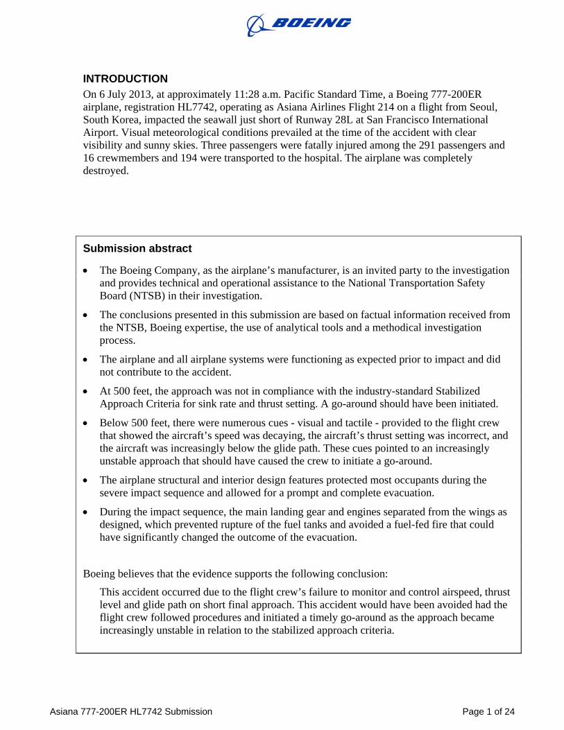
INTRODUCTION On 6 July 2013, at approximately 11:28 a.m. Pacific Standard Time, a Boeing 777-200ER airplane, registration HL7742, operating as Asiana Airlines Flight 214 on a flight from Seoul, South Korea, impacted the seawall just short of Runway 28L at San Francisco International Airport. Visual meteorological conditions prevailed at the time of the accident with clear visibility and sunny skies. Three passengers were fatally injured among the 291 passengers and 16 crewmembers and 194 were transported to the hospital. The airplane was completely destroyed.
Submission abstract
• The Boeing Company, as the airplane’s manufacturer, is an invited party to the investigation and provides technical and operational assistance to the National Transportation Safety Board (NTSB) in their investigation.
• The conclusions presented in this submission are based on factual information received from the NTSB, Boeing expertise, the use of analytical tools and a methodical investigation process.
• The airplane and all airplane systems were functioning as expected prior to impact and did not contribute to the accident.
• At 500 feet, the approach was not in compliance with the industry-standard Stabilized Approach Criteria for sink rate and thrust setting. A go-around should have been initiated.
• Below 500 feet, there were numerous cues - visual and tactile - provided to the flight crew that showed the aircraft’s speed was decaying, the aircraft’s thrust setting was incorrect, and the aircraft was increasingly below the glide path. These cues pointed to an increasingly unstable approach that should have caused the crew to initiate a go-around.
• The airplane structural and interior design features protected most occupants during the severe impact sequence and allowed for a prompt and complete evacuation.
• During the impact sequence, the main landing gear and engines separated from the wings as designed, which prevented rupture of the fuel tanks and avoided a fuel-fed fire that could have significantly changed the outcome of the evacuation.
Boeing believes that the evidence supports the following conclusion:
This accident occurred due to the flight crew’s failure to monitor and control airspeed, thrust level and glide path on short final approach. This accident would have been avoided had the flight crew followed procedures and initiated a timely go-around as the approach became increasingly unstable in relation to the stabilized approach criteria.
Asiana 777-200ER HL7742 Submission Page 2 of 24
BOEING ASSISTANCE WITH THIS INVESTIGATION The NTSB is conducting the investigation into this Asiana 777-200ER landing accident. Assisting the NTSB in their investigation are the Federal Aviation Administration (FAA), Asiana, Boeing and other designated parties.
As the manufacturer of the 777-200ER airplane, Boeing’s specific role in this investigation has been to provide technical information regarding the airplane design, manufacture and operation to assist the NTSB.
Furthermore, the NTSB requested that all parties submit proposed findings to be drawn from the factual information established during the course of the investigation. Boeing has responded to the NTSB request with this document, which:
• Provides an assessment of the factual information and other pertinent data.
• Identifies knowledge gained from the investigation.
• Identifies conclusions and recommendations supported by the knowledge gained from the investigation.
BOEING ASSESSMENT The Boeing assessment of the accident is based upon the facts as documented in the NTSB’s factual reports. These reports are observations of the airplane and accident site, post-accident examination of airplane systems and components, flight data recorder (FDR) data, the cockpit voice recorder (CVR) transcript, and flight crew interview data.
Asiana 777-200ER HL7742 Submission Page 3 of 24
WEATHER No significant weather was reported at the time of the accident. METARS indicated that the ambient air temperature was 65 degrees F, dew point was 50 degrees F with clear skies and greater than 10 miles visibility. The CVR contained a discussion by the crew about various landmarks seen and identified during the approach. The reported winds were from 210 degrees at 7 knots. The actual winds, calculated from FDR data, confirmed a small, quartering tailwind at the time of impact with a tailwind of 8 knots and a crosswind from the left of 5 knots. This is well within the normal capability of the 777 airplane. Therefore, weather was not a factor in this accident.
THE AIRPORT The accident occurred at San Francisco International Airport (SFO). SFO has two pairs of intersecting runways and is at an elevation of 13 feet Mean Sea Level (MSL). Asiana 214 was attempting to land on Runway 28L, which is 11,381 feet long and 200 feet wide.
ILS Guidance SFO Runway 28L is normally equipped with an Instrument Landing System (ILS) and a Precision Approach Path Indicator (PAPI) visual landing system. Recent construction work had been completed on runway 28L, which included displacing the runway threshold 300 feet further down the runway. When the threshold was displaced, it necessitated moving the ILS glideslope antenna and PAPI lights to match the new threshold location. This phase of the construction did not affect the ILS Localizer antenna, which remained operational. At the time of the accident, the displaced threshold, the relocated PAPI and ILS Localizer were active and in use, but the relocated ILS glideslope had not yet been activated on Runway 28L. A Notice to Airmen (NOTAM) correctly indicated that the ILS glideslope was out of service at the time of the accident. The flight1 crew of Asiana 214 received, and was aware of, the NOTAM that the ILS glideslope on Runway 28L at SFO was not operational.
PAPI Guidance An FAA Flight Inspection checked and confirmed the PAPI calibration was within requirements on July 2, 2013, four days before the accident.2 During the post-impact breakup, the airplane fuselage destroyed three of the four PAPI lights located 1448 feet beyond the displaced threshold on the left side of the runway. As such, it was not possible to confirm the accuracy and calibration of the PAPI lights after the accident. Neither the accident crew nor the flights that landed before it reported any issues with the PAPI lights. Therefore, the PAPI lights were illuminated and accurately calibrated at the time of the accident.
VERTICAL GUIDANCE DISPLAYED IN THE FLIGHT DECK During the approach, vertical guidance was also displayed in the flight deck via the Vertical Path Indicator (VPI) on the navigation display.3 The VPI indicates where the airplane is in relation to a virtual glide path that is calculated by the flight management computer. The center white line on the scale represents the airplane and the magenta diamond represents the calculated glide path. The full scale white lines represent ±400 feet above or below the airplane. If the center white line is above the magenta diamond , the airplane is above the glide path, as shown in the depiction to the right. 1 NTSB Operations Group Chairman’s Factual Report, dated 15 Nov 2013, page 9 2 NTSB Aircraft Performance Group Crash Site Factual Report, dated 6 Dec 2013, page 13 3 Boeing 777 Flight Crew Operations Manual (FCOM), page 11.31.25, NTSB Operations Group Chairman’s Factual Report, dated 15 Nov 2013, page 25
Asiana 777-200ER HL7742 Submission Page 4 of 24
FLIGHT CREW Three Captains and one First Officer were assigned to Asiana Flight 214. Of those four, one Captain and one First Officer were assigned to be cruise relief pilots. During the descent and approach, the cruise relief Captain was seated in the aircraft’s passenger cabin. The remaining three pilots were in the flight deck during the accident landing as described below.
Left Seat - Trainee Captain - Pilot Flying The pilot in the left seat was the Pilot Flying (PF) on the accident flight. He was a Trainee Captain who was completing his Operational Experience in the B777 as part of his transition training to become a B777 Captain. After more than five years as an A320 Captain, on 25 March 2013, the Trainee Captain began transition training to become a Captain on the B777. During his time as an A320 Captain he also served as an A320 ground school instructor, A320 simulator instructor and A320 operating experience instructor pilot.
Prior to the accident flight, the Trainee Captain had completed eight flight legs and 33:31 hours of the 20 flight legs and 60 hours required to complete the transition to 777 Captain. His most recent training flight prior to the accident was on July 4, 2013, two days before the accident. The instructor pilot on that previous flight was not sure if the Trainee Captain was making normal progress. The instructor stated that the Trainee Captain was not well organized or prepared, that he conducted inadequate briefings, and that he deviated from multiple standard operating procedures. The instructor also explained that the Trainee Captain had allowed the descent path to become low at an altitude of 200 to 100 feet and his descent rate had been high on short final.4
The trainee captain stated in an interview he found flying the approach to SFO very stressful. He stated it was very difficult to perform a visual approach with a heavy airplane. Asked whether he was concerned about his ability to perform the visual approach, he said “very concerned, yea.”5
Right Seat - Instructor Captain - Pilot Monitoring - Instructor Pilot - Pilot-In-Command The pilot in the right seat was an Instructor Captain for the transitioning Trainee Captain in the left seat. He had three distinct responsibilities on the accident flight: (1) he was the Pilot Monitoring (PM); (2) he was the Instructor Pilot (IP) for the Trainee Captain; and (3) he was Pilot-In-Command (PIC). He had been a B777 Captain since January 16, 2008, and became qualified as a B777 Instructor Pilot on June 12, 2013. The accident flight was his first time acting as an instructor conducting operating experience.
Observer Seat – Relief First Officer The relief First Officer served as an Observer in the middle observer seat during the approach and landing. He was hired by Asiana on December 12, 2007, flying as First Officer on the A320, and then as a First Officer on the B777 since March 3, 2012.6
Table 1 - Flight Crew Summary Trainee Captain Instructor Captain First Officer
Seat during accident landing Left Seat Right Seat Observer Seat Responsibility on accident landing PF PM, IP, PIC Observer
Total pilot flying time 9,684 hours 12,307 hours 4,557 hours Total Pilot-In-Command time 3,729 hours 9,045 hours 1,445 hours
Total 777 flying time 33 hours 3,208 hours 715 hours
4 NTSB Operations Group Chairman’s Factual Report, dated 15 Nov 2013, page 12 5 NTSB Operations Group Chairman’s Factual Report, dated 15 Nov 2013, page 9 6 NTSB Operations Group Chairman’s Factual Report, dated 15 Nov 2013, page 17
Asiana 777-200ER HL7742 Submission Page 5 of 24
SEQUENCE OF EVENTS Below is a chronological analysis of the accident approach based on the FDR data and the CVR transcript.7 Each event below is referenced by time to impact, airplane altitude, and distance to the runway threshold. Relevant FDR/CVR data points are provided followed by a discussion of the significant data points. For ease of reference, CVR transcript excerpts are color coded: Trainee Captain/PF (green), Instructor Captain/PM (blue), Relief First Officer/OBS (pink), and EGPWS (red). Boeing FDR plots with CVR statements overlaid plots are provided in Appendix 1, in support of this discussion.
Time to Impact Altitude Distance to Threshold Reference
-90:00 n/a n/a n/a
Discussion: The trainee captain stated in an interview that he returned to the cockpit one hour and 30 minutes before the flight’s estimated time of arrival. According to the relief FO, he and the relief captain gave some tips to the trainee captain, including the likelihood of getting “shortcut” vectoring and the possibility of being held at high altitude for longer than normal during the approach.8
Time to Impact Altitude Distance to Threshold Reference
-15:15 ~11,000 feet n/a n/a
CVR/FDR: PM: {FO @, monitoring well please in the back.} (CVR 11:12:33.7) Obs: {yes sir.} (CVR 11:12:39.6)
PM: {let us know immediately if anything strange shows. . .} (CVR 11:12:40.3)
Discussion: About 15 minutes before impact, the PM instructed the Observer to monitor and to speak up if he sees anything. This is normal and expected CRM practice for the PIC to brief and empower an observer to be involved in the flight.
Time to Impact Altitude Distance to Threshold Reference
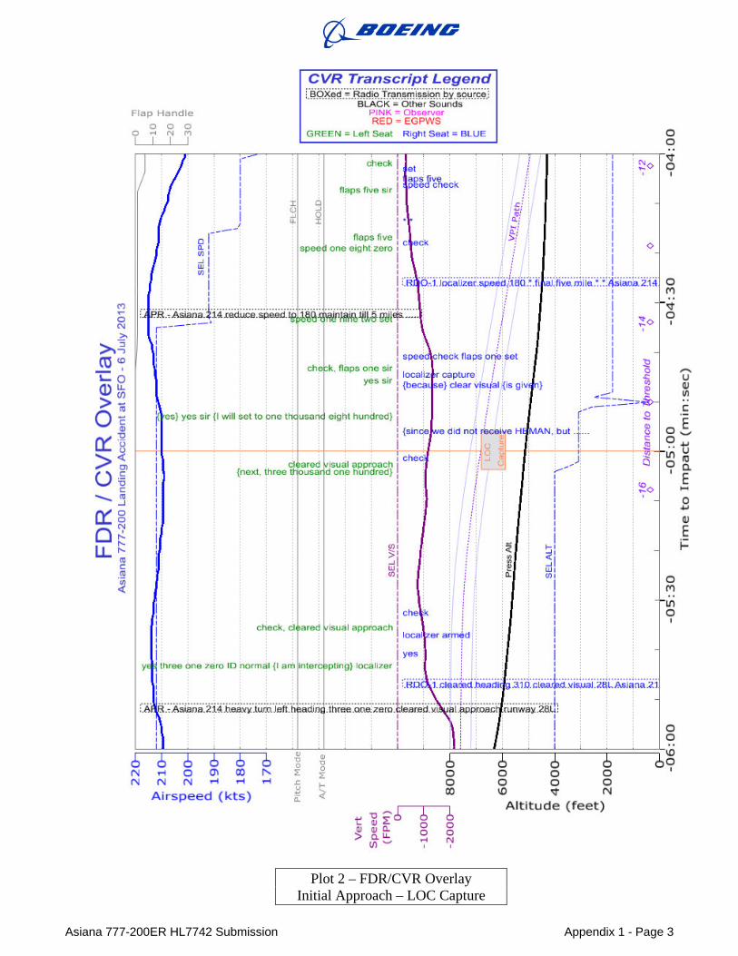
-4:45 4,800 feet 14.7 nautical miles Appendix 1, Plots 1-2
CVR/FDR: FDR: Localizer (LOC) capture PM: Localizer capture. (CVR 11:23:05.2)
Discussion: The CVR Transcript shows that the PM acknowledged LOC capture. The airplane is established on the extended runway centerline, with autopilot and autothrottle engaged in Flight Level Change (FLCH SPD) and HOLD modes, respectively. The airplane was above the equivalent 3 degree glideslope, but descending at 1400 feet/minute (FPM). However, the airspeed had increased above the Mode Control Panel (MCP) Selected Speed which caused the autopilot to decrease the rate of descent.
7 NTSB CVR Group Chairman’s Factual Report, dated 11 Dec 2013 8 NTSB Operations Group Chairman’s Factual Report, dated 15 Nov 2013, page 5
Asiana 777-200ER HL7742 Submission Page 6 of 24
Time to Impact Altitude Distance to Threshold Reference
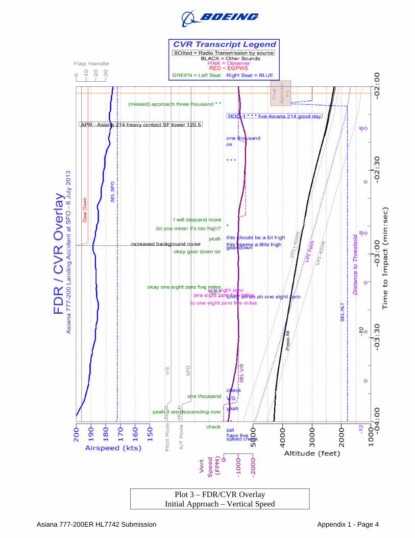
-3:53 4,250 feet 11.5 nautical miles Appendix 1, Plot 3
CVR/FDR: PM: {* *.} (CVR 11:23:49.5) PF: {yeah, I am descending now.} (CVR 11:23:53.2) PM: yeah. (CVR 11:23:54.4)
FDR: autopilot to V/S mode (1,000 feet/minute) PF: one thousand. (CVR 11:23:58.8) PM: V/S (CVR 11:23:58.0)
PM: Check. (CVR 11:24:00.9) …
PM: {this seems a little high.} (CVR 11:24:53.0) PF: {yeah} (CVR 11:24:55.2)
PM: {this should be a bit high} (CVR 11:24:55.6)
PF: {do you mean it’s too high?} (CVR 11:24:58 9}
PM: {*} (CVR 11.24:59.6)
PF: {I will descend more} (CVR 11:25:02.0)
FDR: V/S to 1,500 feet/minute … [for approximately 26 seconds] FDR: V/S to 1,000 feet/minute PM: {one thousand} (CVR 11:25:31.2)
Discussion: At about 4,250 feet the flight crew perceived that the plane was high. They engaged the autopilot Vertical Speed (V/S) mode and the plane began to descend at 1,000 feet/minute, which was the selected V/S on the MCP. The rate of descent was insufficient to put the aircraft on the glidepath. The PM raised the issue of being high again, and the crew increased the V/S to 1,500 feet/minute. However, the V/S remained at 1,500 feet/minute for only 26 seconds, after which it was set back to 1,000 feet/minute. The PM called out the change back to 1,000 feet/minute.
Analysis: The flight crew perceived that the plane was high but the actions taken were insufficient to resolve the high on glidepath situation. The high on glidepath situation would have been improved had a greater descent rate been briefed and used.
Time to Impact Altitude Distance to Threshold Reference
-2:08 2,300 feet 5.5 nautical miles Plot 3
CVR/FDR: FDR: MCP Sel Alt is set to 3000 feet. PF: (missed) approach three thousand * *. (CVR 11:25:43.4) FDR: airplane passes the Final Approach Fix (5.2 nautical miles)
Discussion: At about 2,300 feet, the missed approach altitude was set on the MCP, which is an appropriate and expected action. Shortly after setting the missed approach altitude, the aircraft reached the Final Approach Fix (FAF). At the FAF the aircraft was more than 400 feet above the glidepath. The autopilot and autothrottle remained engaged in V/S and SPD modes, respectively.

Asiana 777-200ER HL7742 Submission Page 7 of 24
Time to Impact Altitude Distance to Threshold Reference
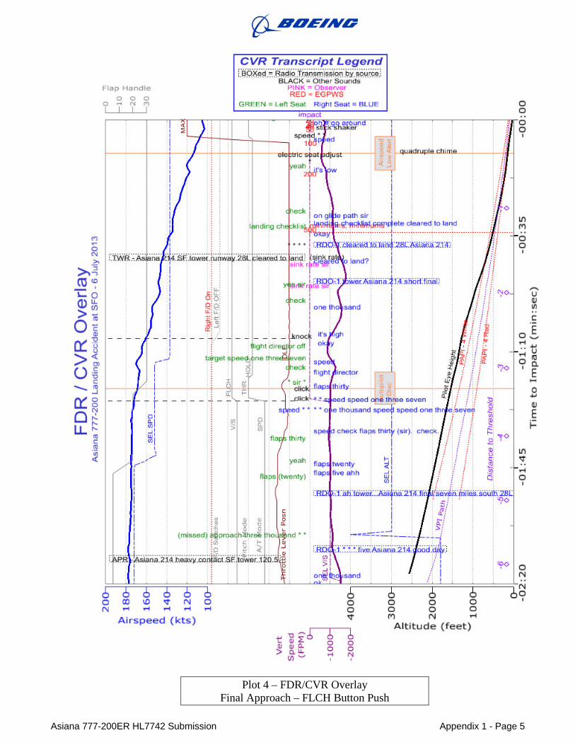
-1:25 1,600 feet 3.5 nautical miles Appendix 1, Plot 4
CVR/FDR: CVR: [sound of click] (CVR 11:26:24.6) FDR: autopilot changes to FLCH SPD, autothrottle to THR mode CVR: [sound of click] (CVR 11:26:27.6) FDR: autopilot is disconnected and flap handle is moved to 30 PM: flaps thirty. (CVR 11:26:28.3) PF: * sir *. (CVR 11:26:29.5) FDR: thrust levers are retarded to the idle stop, FDR: autothrottle changes to HOLD mode PM: flight director. (CVR 11:26:32.5)
Discussion: At about 1,600 feet the FDR data shows that the crew selected the autopilot’s FLCH SPD mode. This action commanded the autopilot to climb, since the 3000 feet missed approach altitude had been set on the MCP. The selection of a FLCH SPD climb at this point was an action contrary to the crew’s intent to land, the briefed approach, and Boeing’s recommendations. In a post-accident interview the PF stated he considered pressing the FLCH pushbutton to obtain a higher descent rate but he could not recall what he did for sure.9 The CVR recorded sound of click at the same time the FDR shows the FLCH SPD mode activated, which confirms that the button was pushed.
To correct this error and cancel the climb, the crew disconnected the autopilot and manually retarded the throttles to the idle stop. One push of the autopilot disconnect button disconnects the autopilot with an accompanying autopilot disconnect warning wailer. Two successive pushes of the button disconnects the autopilot and suppresses the aural warning. No disconnect warning was heard on the CVR, indicating that the crew disconnected the autopilot by pushing the disconnect button twice. The FDR also shows the autothrottle commanding the throttles to advance to accomplish the climb, but shortly afterwards, the throttle levers retard to idle. This indicates a manual override of the autothrottle by the crew which told the autothrottle that the pilot was taking control of thrust and caused the autothrottle to transition to HOLD mode. As with all mode changes, this mode change was displayed on the Flight Mode Annunciator (FMA) and highlighted for 10 seconds with a green box.
Analysis: At this point, both flight directors were on and were providing guidance for a climb to 3000 feet, but the autothrottle had been put in HOLD by the action of the PF, which prevented the autothrottle from adding thrust to accomplish the commanded climb. The crew was flying manually, was descending and was not following the flight director guidance to climb. Therefore, the crew was manually flying something different than what they had commanded the autoflight system to accomplish. The flight crew had overridden and was ignoring the autoflight modes they had chosen.
9 NTSB Operations Group Chairman’s Factual Report, dated 15 Nov 2013, page 6
Asiana 777-200ER HL7742 Submission Page 8 of 24
During this sequence, the PF made an unintelligible statement “* sir *.” The PM, who had just moved the flap handle to 30, acknowledged with “flight director,” which is the proper callout for this AFDS mode change. In his first interview, the PM stated that “…around 1,500 feet, the PF said ‘manual flight’ and disconnected the autopilot. He confirmed the disconnect on the FMA (flight mode annunciator) and called ‘FD (flight director) off.’ ”10 This does not agree with the CVR transcript.
During the PM’s third post-accident interview, he was “… asked whether he noticed the autothrottle transition to HOLD mode, he said no.”11
During his post-accident interview, the PF acknowledged that engaging FLCH at this point would be “very dangerous” because the missed approach altitude had already been set and therefore activating FLCH would cause the aircraft to climb rather than continuing the approach.12
Neither the use of FLCH nor a climb after the FAF was part of the crew’s briefed landing.13 Additionally, selection of FLCH at this point was contrary to Boeing’s guidance that “…the use of FLCH is not recommended after the FAF.”14 Therefore, the FLCH button was erroneously pushed by the crew at about 1,600 feet, causing the airplane to attempt to climb.
10 NTSB Operations Group Factual Report-Attachment 1- Interview Summaries, page 10 11 NTSB Operations Group Chairman’s Factual Report, Exhibit 02-B, page 20 12 NTSB Operations Group Chairman’s Factual Report, Exhibit 02-B, pages 26 13 NTSB CVR Group Chairman’s Factual Report, dated 11 Dec 2013, page 12-8 14 Boeing FCTM , page 5.26
Asiana 777-200ER HL7742 Submission Page 9 of 24
Time to Impact Altitude Distance to Threshold Reference
-1:05 1,250 feet 2.6 nautical miles Appendix 1, Plot 4
CVR/FDR: PF: flight director off. (CVR 11:26:40.4)
PM: okay. (CVR 11:26:41.3) CVR: [sound of knock] (CVR 11:26:43.4) FDR: Left FD goes to Off, right FD stays on PM: {it's high.} (CVR 11:26:44.0)
Discussion: At about 1,250 feet the left flight director switch was turned off, but the right switch remained on. Turning one of the switches off causes the flight director commands to disappear from the PFD on the same side as the switch that was turned off, but otherwise has no effect on the autopilot and autothrottle modes. Turning both switches off at the same time clears the Autopilot Flight Director System (AFDS) modes, which would have caused the autothrottle to transition to SPD mode.15 In his post-accident interview, the PM stated that he “turned the left side [flight director] off and the right side off then on.”16 The FDR does not corroborate this statement. Instead, the FDR data show only the left flight director is turned off, but the right flight director stays on. Additionally, the CVR recording of “[sound of knock]” is timed correctly and is consistent with just one flight director switch being moved, instead of multiple “knock” sounds that should have been heard if both switches were turned off and then one was turned back on. As a result, the flight director guidance and autothrottle remained in the modes previously commanded by the crew: FLCH SPD and HOLD respectively.
The Boeing FCTM does not provide specific recommendations as to whether flight director should be used during a visual approach.17 However, the Boeing FCTM specifically states: “Ensure the proper flight director modes are selected for the desired maneuver. If the flight director commands are not to be followed, the flight director should be turned off”.18
Analysis: During the approach, both flight director switches were not cycled to OFF. This step, which is included in the Boeing Flight Crew Training Manual (FCTM) guidance for a non-ILS instrument approach, is intended to eliminate unwanted flight director guidance for the PF.19 In this case, this step was an opportunity to modify the commanded FLCH SPD and HOLD modes. Had both flight director switches been cycled to OFF, the autothrottle would have reset to the SPD mode and would have resumed control of airspeed.
15 Transcript - Public Hearing Full, page 48, lines 12-23 16 NTSB Operations Group Chairman’s Factual Report, Attachment 1, pages 8, 11 17 Boeing FCTM, Visual Approach, page 5.59 - 5.61 18 Boeing FCTM, Manual Flight, page 1.34 19 Boeing FCTM, Final Approach using V/S or FPA, page 5.45
Time to Impact
-0:51
CVRIFDR: Obs: PF: PM: Obs:
Altitude
900 feet
sink rate sir. yes sir.
r[J-aDEING
Distance to Threshold
1.9 nautical miles
[on radio] tower Asian a two one four short final. sink rate sir.
Snapshot of Backdrive Animation at 800 feet:
Tme ~ -47.8
Reference
Appendix 1, Plot 4
(CVR 11:26:58.6)
(CVR 11:26:59.1)
(CVR 11:26:59.5)
(CVR 11:27:05.1)
AAA 214
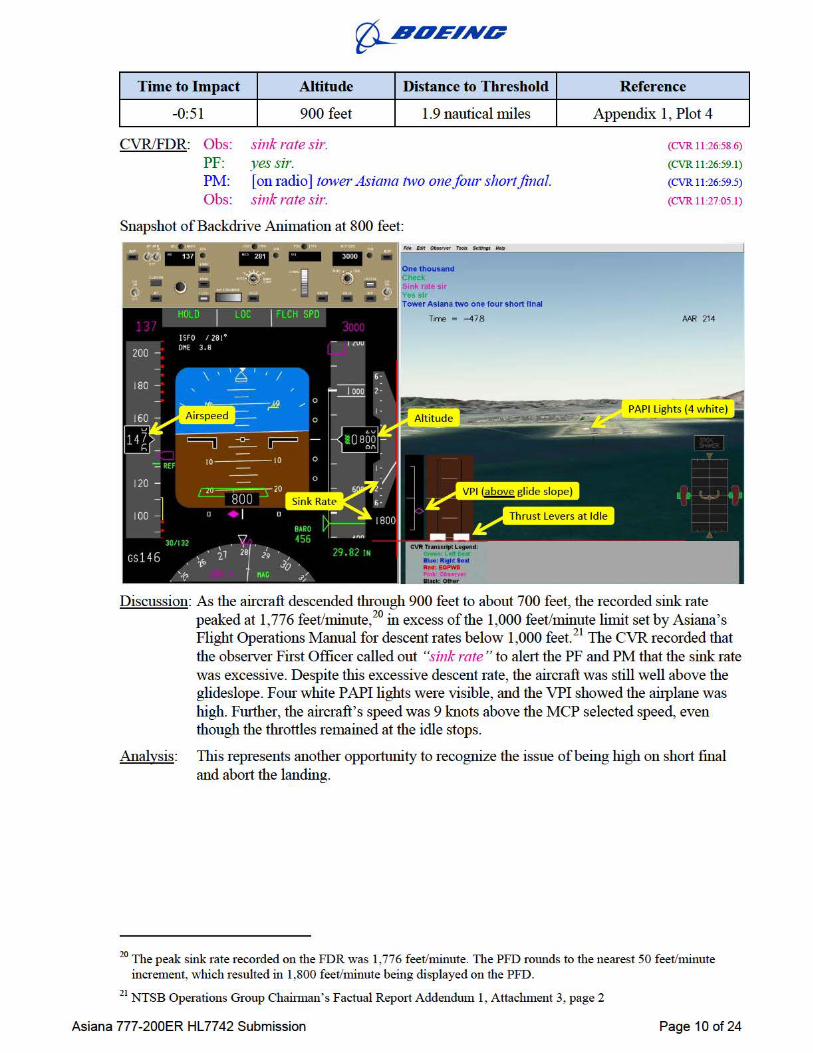
Discussion: As the aircraft descended through 900 feet to about 700 feet, th e recorded sink rate peaked at 1, 77 6 feet/minute, 20 in excess of the 1, 000 feet/minute limit set by Asiana' s Flight Operations Manual for descent rates below 1,000 feet. 21 The CVR recorded that the obse1ver First Officer called out "sink rate " to ale1t the PF and PM that the sink rate was excessive. Despite this excessive descent rate, the aircraft was still well above the glideslope. Four white PAPI lights were visible, and the VPI showed the aiiplane was high. Fmther, the aircraft's speed was 9 knots above the MCP selected speed, even though the tluottles remained at the idle stops.
Analysis: Tins represents another oppmtmlity to recognize the issue of being high on shmt final and abmt the landing.
20 The peak sink rate recorded on the FDR was 1,776 feet/minute. The PFD rmmds to the nearest 50 feet/minute increment, which resulted in 1,800 feet/minute being displayed on the PFD.
21 NTSB Operations Group Chainnan's Factual RepmtAddendwn 1, Attachment 3, page 2
Asiana 777-200ER HL7742 Submission Page 10 of 24
Time to Impact
-0:34
CVRIFDR: CVR: PF: CVR:
r[J-aDEING
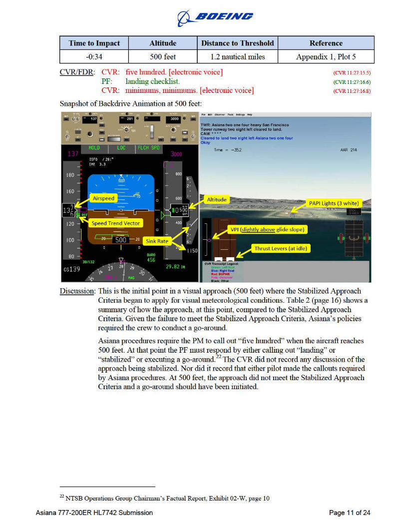
Altitude Distance to Threshold
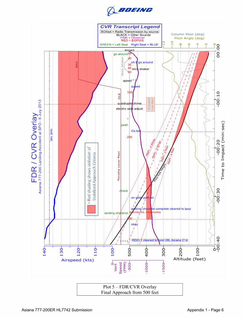
500 feet 1.2 nautical miles
five hundred. [electronic voice] landing checklist. m.inimums, m.inimunlS. [electronic voice]
Snapshot ofBackdrive Animation at 500 feet:
t o land two efght left Asl•a two one four
Time = -:352
Reference
Appendix 1, Plot 5
(CVR 11:27:15.5)
(CVR 11:27:16.6)
(CVR 11:27:16.8)
APfl 214
Discussion: Tills is the initial point in a visual approach (500 feet) where the Stabilized Approach Criteria began to apply for visual meteorological conditions. Table 2 (page 16) shows a summaty of how the approach, at this point, compru·ed to the Stabilized Approach Criteria. Given the failure to meet the Stabilized Approach Criteria, Asiat1a's policies required the crew to conduct a go-ru·ound.
Asiana procedures require the PM to call out "five hlmdred" when the aircraft reaches 500 feet. At that point the PF must respond by either calling out "landing" or "stabilized" or executing a go-ru·ound. 22 The CVR did not record any discussion of the approach being stabilized. Nor did it record that either pilot made the callouts required by Asiana procedures. At 500 feet, the approach did not meet the Stabilized Approach Criteria and a go-around should have been initiated.
22 NTSB Operations Group Chainnan's Factual Repmt, Exhibit 02-W, page 10
Asiana 777-200ER HL7742 Submission Page 11 of 24
Time to Impact
-0:27
CVRIFDR: PM: PM: PF: FDR:
r[J-aDEING
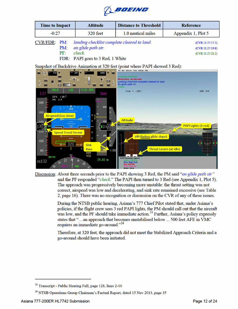
Altitude Distance to Threshold
320 feet 1.0 nautical miles
landing checklist complete cleared to land. on glide path sir. check. P API goes to 3 Red, 1 White
Reference
Appendix 1, Plot 5
(CVR 11:27:17.5)
(CVR 11:27:19.8)
(CVR 11:27:212)
Discussion: About three seconds prior to the PAPI showing 3 Red, the PM said "on glide path sir" and the PF responded "check." The PAPI then tumed to 3 Red (see Appendix 1, Plot 5). The approach was progressively becoming more unstable: the thmst setting was not conect, airspeed was low and decelerating, and sink rate remained excessive (see Table 2, page 16). There was no recognition or discussion on the CVR of any of these issues.
During the NTSB public hearing, Asiana's 777 Chief Pilot stated that, lmder Asiana's policies, if the flight crew sees 3 red P API lights, the PM should call out that the aircraft was low, and the PF should take immediate action.23 Further, Asiana's policy expressly states that" ... an approach that becomes unstabilised below ... 500 feet AFE in VMC requires an immediate go-around."24
Therefore, at 320 feet, the approach did not meet the Stabilized Approach Criteria and a go-around should have been initiated.
23 Transcript - Public Hearing Full, page 128, lines 2-10 24 NTSB Operations Group Chainnan's Factual Repmt, dated 15 Nov 2013, page 35
Asiana 777-200ER HL7742 Submission Page 12 of 24
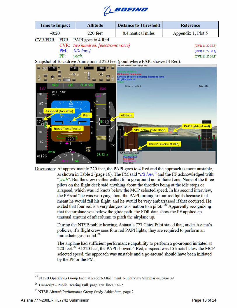
Time to Impact Altitude
-0:20 220 feet
CVRIFDR: FDR: CVR: PM: PF:
r[J-aDEING
Distance to Threshold
0.4 nautical miles
Reference
Appendix 1, Plot 5
(CVR 11:27:323)
(CVR 11:27:33.6)
(CVR 11:27:34.8)
Discussion: At approximately 220 feet, the PAPI goes to 4 Red and the approach is more 1mstable, as shown in Table 2 (page 16). The PM said "it's low, " and the PF acknowledged with "yeah". But the crew neither called for a go-armmd nor initiated one. None of the three pilots on the flight deck said anything about the throttles being at the idle stops or airspeed, which was 15 knots below the MCP selected speed. In his second intetview, the PF said "he was wonying about the P API nnning to fom red lights because that meant he would fail his flight, and he would be vety emban assed if that occuned. He added that fom red is a ve1y dangerous sit11ation to a pilot."25 Apparently recognizing that the airplane was below the glide path, the FDR data show the PF applied an unusual ammmt of aft cohnnn to pitch the airplane up.
Dming the NTSB public hearing, Asiana's 777 ChiefPilot stated that, 1mder Asiana's policies, if a flight crew sees fom red P API lights, they are required to perfmm an immediate go-armmd. 26
The airplane had sufficient peifotmance capability to perfmm a go-armmd initiated at 220 feet. 27 At 220 feet, the P API showed 4 Red, airspeed was 15 knots below the M CP selected speed, the approach was unstable and a go-around should have been initiated by the PF or the PM.
25 . 1 1 . . NTSB OperatiOns Group Factua Repmt-Attac unent 1- Interview Sununanes, page 39 26 Transcript - Public Hearing Full, page 128, lines 23-25 27 NTSB Aircraft Perfonnance Group Study Addendum, page 2
Asiana 777-200ER HL7742 Submission Page 13 of 24
Asiana 777-200ER HL7742 Submission Page 14 of 24
Time to Impact Altitude Distance to Threshold Reference
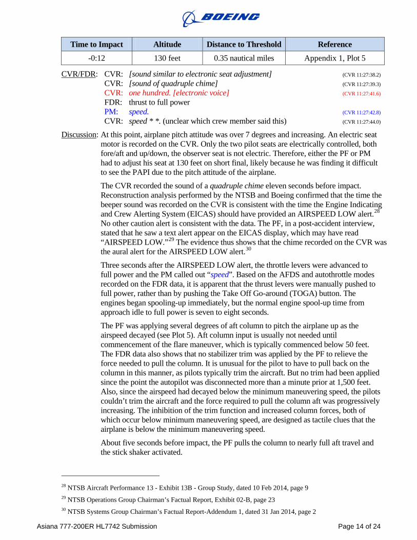
-0:12 130 feet 0.35 nautical miles Appendix 1, Plot 5
CVR/FDR: CVR: [sound similar to electronic seat adjustment] (CVR 11:27:38.2) CVR: [sound of quadruple chime] (CVR 11:27:39.3) CVR: one hundred. [electronic voice] (CVR 11:27:41.6) FDR: thrust to full power PM: speed. (CVR 11:27:42.8) CVR: speed * *. (unclear which crew member said this) (CVR 11:27:44.0)
Discussion: At this point, airplane pitch attitude was over 7 degrees and increasing. An electric seat motor is recorded on the CVR. Only the two pilot seats are electrically controlled, both fore/aft and up/down, the observer seat is not electric. Therefore, either the PF or PM had to adjust his seat at 130 feet on short final, likely because he was finding it difficult to see the PAPI due to the pitch attitude of the airplane.
The CVR recorded the sound of a quadruple chime eleven seconds before impact. Reconstruction analysis performed by the NTSB and Boeing confirmed that the time the beeper sound was recorded on the CVR is consistent with the time the Engine Indicating and Crew Alerting System (EICAS) should have provided an AIRSPEED LOW alert.28 No other caution alert is consistent with the data. The PF, in a post-accident interview, stated that he saw a text alert appear on the EICAS display, which may have read “AIRSPEED LOW.”29 The evidence thus shows that the chime recorded on the CVR was the aural alert for the AIRSPEED LOW alert.30
Three seconds after the AIRSPEED LOW alert, the throttle levers were advanced to full power and the PM called out “speed”. Based on the AFDS and autothrottle modes recorded on the FDR data, it is apparent that the thrust levers were manually pushed to full power, rather than by pushing the Take Off Go-around (TOGA) button. The engines began spooling-up immediately, but the normal engine spool-up time from approach idle to full power is seven to eight seconds.
The PF was applying several degrees of aft column to pitch the airplane up as the airspeed decayed (see Plot 5). Aft column input is usually not needed until commencement of the flare maneuver, which is typically commenced below 50 feet. The FDR data also shows that no stabilizer trim was applied by the PF to relieve the force needed to pull the column. It is unusual for the pilot to have to pull back on the column in this manner, as pilots typically trim the aircraft. But no trim had been applied since the point the autopilot was disconnected more than a minute prior at 1,500 feet. Also, since the airspeed had decayed below the minimum maneuvering speed, the pilots couldn’t trim the aircraft and the force required to pull the column aft was progressively increasing. The inhibition of the trim function and increased column forces, both of which occur below minimum maneuvering speed, are designed as tactile clues that the airplane is below the minimum maneuvering speed.
About five seconds before impact, the PF pulls the column to nearly full aft travel and the stick shaker activated.
28 NTSB Aircraft Performance 13 - Exhibit 13B - Group Study, dated 10 Feb 2014, page 9 29 NTSB Operations Group Chairman’s Factual Report, Exhibit 02-B, page 23 30 NTSB Systems Group Chairman’s Factual Report-Addendum 1, dated 31 Jan 2014, page 2
r[J-aDEING
Time to Impact Altitude Distance to Threshold
0:00 0 feet ---
CVRIFDR: FDR: Impact based on recorded acceleration parameters CVR: [sound similar to impact]
Reference
Appendix 1, Plot 5
(CVR 11:27:50.3)
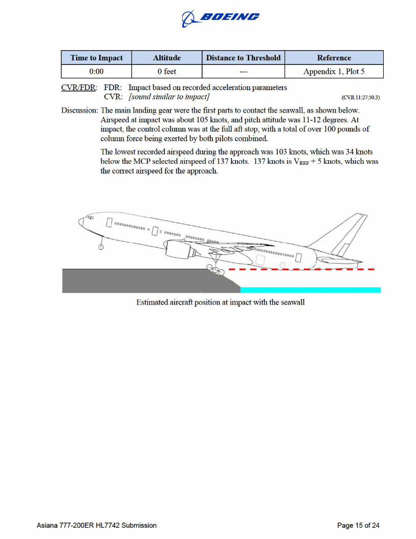
Discussion: The main landing gear were the first palis to contact the seawall, as shown below. Airspeed at impact was about 105 knots, and pitch attitude was 11-12 degrees. At impact, the control column was at the full aft stop, with a total of over 100 pounds of column force being exetted by both pilots combined.
The lowest recorded airspeed during the approach was 103 knots, which was 34 knots below the MCP selected airspeed of 137 knots. 137 knots is VREF + 5 knots, which was the conect airspeed for the approach.
Estimated aircraft position at impact with the seawall
Asiana 777-200ER HL7742 Submission Page 15 of 24
Asiana 777-200ER HL7742 Submission Page 16 of 24
STABILIZED APPROACH CRITERIA The Boeing Flight Crew Training Manual (FCTM) contains recommended Stabilized Approach Criteria based on criteria developed by the Flight Safety Foundation. These are industry accepted recommendations. The basic stabilized approach recommendations by Boeing are identical to those found in Asiana’s manuals. Both Boeing and Asiana have seven criteria:
1. The airplane must be on the correct flight path
2. Only small changes in heading and pitch are required to maintain the correct flight path
3. Airspeed must be within +10 knots or -5 knots of the target airspeed
4. The aircraft must be in the correct landing configuration
5. Sink rate should not exceed 1,000 feet/minute unless a special briefing is conducted
6. The thrust setting should be appropriate
7. All briefings and checklists should be complete
Boeing’s FCTM further states: “All approaches should be stabilized by … 500 feet AFE in visual meteorological conditions.”31 Asiana’s policy on stabilized approaches is identical: “All approaches should be stabilized by 500 feet above airport elevation in VMC.”32
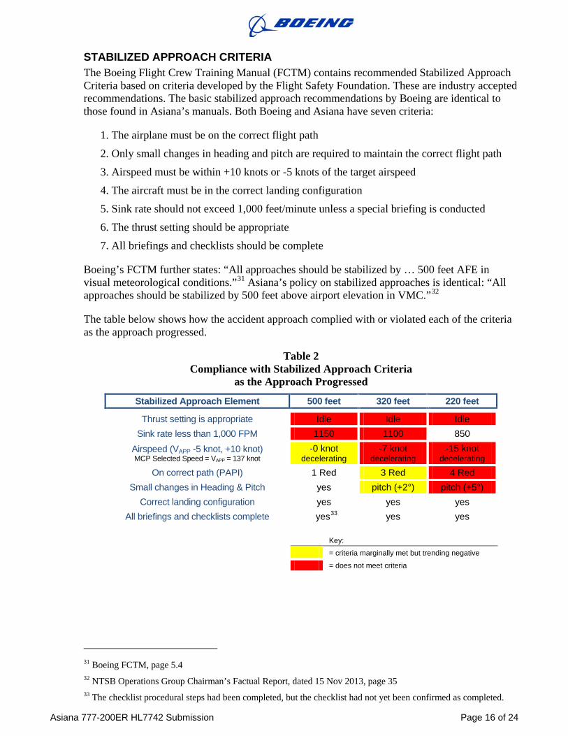
The table below shows how the accident approach complied with or violated each of the criteria as the approach progressed.
Table 2 Compliance with Stabilized Approach Criteria
as the Approach Progressed
Stabilized Approach Element 500 feet 320 feet 220 feet
Thrust setting is appropriate Idle Idle Idle Sink rate less than 1,000 FPM 1150 1100 850
Airspeed (VAPP -5 knot, +10 knot) MCP Selected Speed = VAPP = 137 knot
-0 knot decelerating
-7 knot decelerating
-15 knot decelerating
On correct path (PAPI) 1 Red 3 Red 4 Red Small changes in Heading & Pitch yes pitch (+2°) pitch (+5°)
Correct landing configuration yes yes yes All briefings and checklists complete yes33 yes yes
Key:
= criteria marginally met but trending negative
= does not meet criteria
31 Boeing FCTM, page 5.4 32 NTSB Operations Group Chairman’s Factual Report, dated 15 Nov 2013, page 35 33 The checklist procedural steps had been completed, but the checklist had not yet been confirmed as completed.
Asiana 777-200ER HL7742 Submission Page 17 of 24
ASIANA’S GO-AROUND POLICY Asiana’s policy requires a go-around if, at or below 500 feet on a visual approach, any of the stabilized approach criteria are not met: “An approach that becomes unstabilized below...500 feet AFE in VMC requires an immediate go-around.”34 The investigation data shows that the approach never complied with the stabilized approach criteria at or below 500 feet.
During the NTSB public hearing, Asiana’s 777 Chief Pilot stated that, under Asiana’s policies, if a flight crew sees 3 red PAPI lights, the PM should call out that the aircraft was low, and the PF should take immediate action.35 The investigation data show that 3 red PAPI lights were visible 27 seconds before impact. No callout was made, and the PF did not take any action to effectively remedy the situation. Twenty-seven seconds is more than enough time to recognize the issue and initiate a successful go-around.
Also, during the NTSB public hearing, Asiana’s 777 Chief Pilot stated that, under Asiana’s policies, if a flight crew sees four red PAPI lights, they are required to perform an immediate go-around.36 The investigation data shows that 4 red PAPI lights were visible for at least 20 seconds before impact. Again, this is more than enough time to recognize the issue and initiate a successful go-around.
Below 500 feet, there were numerous cues - visual and tactile - provided to the flight crew that showed the aircraft’s speed was decaying, the aircraft’s thrust setting was incorrect, and the aircraft was increasingly below the glide path. These cues pointed to an increasingly unstable approach that should also have caused the crew to initiate a go-around.
WHO CAN INITIATE A GO-AROUND Asiana’s go-around policy states that the PF may initiate a go-around regardless of whether the PF is the captain or a copilot. But during a post-accident interview, the Trainee Captain (PF) stated that only the IP had the authority to decide to go-around.37
This confusion regarding who was responsible for calling for a go-around may have delayed initiation of a go-around.
34 NTSB Operations Group Chairman’s Factual Report, dated 15 Nov 2013, page 36 35 Transcript - Public Hearing Full, page 128, lines 2-10 36 Transcript - Public Hearing Full, page 128, lines 23-25 37 NTSB Operations Group Chairman’s Factual Report, dated 15 Nov 2013, page 36-37
Asiana 777-200ER HL7742 Submission Page 18 of 24
AIRPLANE PERFORMANCE The simulation results documented by the NTSB Airplane Performance Group’s study of the approach show that the airplane “had adequate performance capability to accomplish a go-around initiated no later than 11 to 12 seconds prior to ground impact (depending on technique), assuming a minimum aft fuselage clearance during the maneuver of 30 feet above ground level (AGL). For reference purposes, the accident flight crew initiated a go-around by advancing the throttles about 7 seconds prior to ground impact.”38 The airplane did not stall.
LOW AIRSPEED ALERT The AIRSPEED LOW alert currently used on Boeing airplanes was developed after an in-service event in 1994 on a 747-400. The 747 experienced pitot probe icing in cruise after the pitot heater failed. This resulted in the throttles slowly retarding toward idle as the autothrottle attempted to hold airspeed. The airspeed decay went unnoticed until the stick shaker activated. The crew recovered the airplane but several thousand feet of altitude were lost during the recovery.39 Boeing examined the event and took action to prevent it from happening again. In addition to system fixes on the 747-400, a low airspeed alert was added to all Boeing models. The low airspeed alert was not part of the original 777 certification in 1995 but was added to the 777 in 1997.
It is now basic on all newly delivered Boeing models. The alert was implemented as an EICAS Caution-level alert on Boeing twin aisle airplanes (767-400, 747-400, 747-8, 777 and 787).40 When the AIRSPEED LOW alert is triggered, an amber box illuminates around current airspeed on the PFD, both Master Caution lights illuminate, an aural beeper (quadruple chime) is issued and amber text message “AIRSPEED LOW” is displayed on EICAS.
On all Boeing production models, the AIRSPEED LOW alert will trigger when the airspeed decreases 30 percent into the amber band. The 30 percent point was intentionally chosen because it is high enough to provided adequate margin to stick shaker but low enough to prevent nuisance alerts.
On the accident approach, the AIRSPEED LOW alert triggered 11 seconds prior to impact, when airspeed was about 114 knots. At that point, radio altitude was 120 feet, which was significantly below the VPI glide path and the PAPI visual path. This accident combined two separate issues: low airspeed and low altitude on short final approach. The AIRSPEED LOW alert provided a timely caution of decreasing airspeed; and the PAPI lights, vertical path indicator and altitude displays provided ample notice of low altitude.
38 NTSB Aircraft Performance Group Study Addendum, page 2 39 Transcript - Public Hearing Full, page 42, line 5 40 The 737-NG models are non-EICAS airplanes. The Airspeed Low alert on the 737-NG at initial delivery in 1997
consisted of a flashing amber box around the current airspeed on the PFD. A voice alert aural was added in 2010 to augment the flashing amber box. An EICAS text message was not an option since the 737 does not have an EICAS system.
Asiana 777-200ER HL7742 Submission Page 19 of 24
AIRPLANE SYSTEMS The NTSB Systems Group removed several components from the wreckage for data download and laboratory examination, including: Mode Control Panel (MCP), Proximity Sensor Electronics Unit (PSEU), Airplane Information Management System (AIMS) cards containing the autothrottle function, throttle levers and autothrottle servos, and Enhanced Ground Proximity Warning System (EGPWS). A more complete description of the results of the examination and testing of these components is documented by the Systems Group Chairman’s Factual Report and Addendum. None of the evidence gathered on-scene or examinations of the removed components revealed a failure of any airplane system that contributed to the accident.
The MCP includes the button used to engage the FLCH autopilot pitch mode and the two Flight Director switches. The Flight Director switches and FLCH button were tested and found to operate normally, even after the multiple severe impacts of the accident sequence and while being subjected to vibration.41 At about 1,600 feet the FDR data shows that the crew selected the autopilot’s FLCH mode. The CVR recorded sound of click at the same time the FDR shows the FLCH mode activated. In a post-accident interview the PF said he considered pressing the FLCH button to obtain a higher descent rate, but he could not remember if he hit the button or not.42 This post-accident testing combined with the FDR data and CVR data confirms that the button was pushed by one of the flight crew at 1,600 feet.
The PSEU, EGPWS and AIMS cards were downloaded and tested and found to be operating normally. An Enhanced Ground Proximity Warning System (EGPWS) was installed and operational on the accident airplane. The expected EGPWS automated altitude callouts were recorded on the CVR during final approach, as shown in the CVR transcript.43 The EGPWS did not issue any alarms prior to impact with the seawall. Analysis of the Asiana 214 flight profile verified that none of the installed EGPWS alarm thresholds would have been penetrated.44 Therefore, it was confirmed that the EGPWS did not, and was not expected to, issue any alarms.
During the post-accident testing of the autothrottle and throttle lever assemblies, an anomaly was found in a sensor. But after reviewing the FDR data and redundant system architecture it was determined that, if even if it was present during the accident flight, this anomalous sensor value had no effect on the autothrottle operation. Additional review of ACARS data from the accident airplane in the flights preceding the accident flight showed no indication that the anomaly was present prior to the accident.
Examination of the FDR data revealed that the airplane was responding normally to crew inputs prior to impact with the seawall. All airplane systems were found to be functioning properly, including the flight controls, autoflight, autothrottle and high lift systems. In addition, no mention of airplane problems was made during interviews with the flight crew45.
Therefore, the airplane and all airplane systems were functioning as expected prior to impact and did not contribute to the accident.
41 NTSB Systems Group Chairman’s Factual Report, dated 21 Nov 2013, pages 21-22 42 NTSB Operations Group Chairman’s Factual Report, dated 15 Nov 2013, page 7 43 NSTB Cockpit Voice Recorder Group Chairman’s Factual Report, dated 11 Dec 13, pages 36-38 44 NTSB Docket Systems 9 - EGPWS Warning Analysis Provided by Honeywell, dated 20 Nov 2013 45 NTSB Operations Group Chairman’s Factual Report, dated 15 Nov 2013
Asiana 777-200ER HL7742 Submission Page 20 of 24
SURVIVAL FACTORS As described at the NTSB Investigative Hearing, the main landing gear and aft fuselage struck the seawall at about 105 knots. The impact caused the attachments for both main landing gear to fuse (shear off) as designed, which allowed the main landing gear to separate without compromising the wing or fuel tank structure. Main landing gear separation was immediately followed by the tail breaking off at the aft pressure bulkhead. This resulted in the airplane sliding along the runway while resting on the engines and aft fuselage.46 During the runway slide, the airplane lifted partially into the air, spun approximately 330 degrees and impacted the ground a second time before coming to rest off of the left side of the runway. Examination of the wreckage showed that the structural design and certification loads had been exceeded during the first and/or second impact.47 Investigative testing has further shown that during the impact sequence the 6 Gs downward and 3 Gs side (inboard) structural and interior design and certification loads were more than doubled in the downward direction and more than quadrupled in the inboard direction.48 The airplane structural and interior design features protected occupants during the severe impact sequence and allowed for a prompt and complete evacuation.
The impact caused the attachments for both main landing gear to fuse (break off) as designed, which allowed the main landing gear to separate without compromising the wing or fuel tank structure. Main landing gear separation was immediate.
Fuel Tank Integrity Examination of the attachment points for the main landing gear showed a clean separation, as designed, due to impact with the seawall. During the runway slide and second impact, the engines separated cleanly from their attach points on the wing spar, also as designed.49 The left engine separated just prior to the 330 degree rotation, and the right engine separated during the second impact after the rotation. Examination of the center and wing fuel tanks showed no evidence of rupture.50 During the impact sequence, the main landing gear and engines separated from the wings as designed, which prevented rupture of the fuel tanks and avoided a fuel-fed fire that could have significantly changed the outcome of the evacuation.
Minor fuel spillage did occur due to impact damage to outboard wing fuel tank access doors51, and from fuel feeder lines to the engines after the engines separated until the fuel pumps lost power shortly after engine separation. These minor fuel spills did not contribute to the post-crash fire.
46 IIC Opening Presentation at the Public Hearing, Slides 12-14 47 NTSB Structures Group Chairman’s Factual Report, dated 22 November 2013 48 NTSB Survival Factors Group Chairman’s Factual Report Addendum #1 – Attachment 1, Slide/raft Testing
Report from MGA Research Corporation, page 3 49 NTSB Structures Group Chairman’s Factual Report, dated 22 November 2013, pages 10-12 50 NTSB Structures Group Chairman’s Factual Report Addendum 1, dated 5 February 2014, pages 3-5 51 NTSB Structures Group Chairman’s Factual Report Addendum 1, dated 5 February 2014, pages 3-4
Asiana 777-200ER HL7742 Submission Page 21 of 24
Post-Crash Fire The post-crash fire initiated outside the main fuselage at the right engine. Examination of video footage of the first responders and evacuation sequence showed that smoke from this fire was not evident in the cabin until about 12 minutes after the airplane came to rest. The fire was slowed by the fire-resistant materials installed in the airplane interior, which were tested post-crash and shown to still pass all applicable certification requirements even after high heat exposure. While smoke was present in the cabin during the latter part of the evacuation, the post-crash fire was not a factor during the evacuation.
Escape Slides Two escape slides deployed inside the cabin during the second impact in the crash sequence.52
Investigative testing demonstrated that the loads required to reproduce the internal escape slide failures that result in deployment were more than double in the downward direction and more than quadruple in the inboard direction the loads the escape slides are required to be designed for and tested to.53 Examination of the fuselage structural components in the wreckage showed evidence of failures resulting from overstress, which indicates excessive loading of the escape slides occurred during the crash sequence.54 The two escape slides deployed inside the passenger cabin as a result of excessive impact loads during the crash sequence.
Seats The passenger seats were designed and certified to protect occupants under loading of at least 16 Gs horizontally and 14 Gs vertically and performed as designed during the multiple impact sequence. Eighty-three percent of passengers and crew were uninjured or received only minor injuries55 despite the excessive impact loads. The majority of severely injured passengers were seated in the aft of the aircraft56 where the structure supporting the seats was heavily damaged by the seawall impact and the floor beams were found to be displaced upward.57 Despite the multiple, excessive impact loads experienced during the crash sequence that severely deformed and damaged the airplane fuselage, the cabin interior remained largely intact, providing clear aisles for egress.
52 NTSB Structures Group Chairman’s Factual Report, dated November 22, 2013, pages 13-14 53 NTSB Survival Factors Group Chairman’s Factual Report Addendum #1 – Attachment 1,
Slide/raft Testing Report from MGA Research Corporation, page 3 54 NTSB Structures Group Chairman’s Factual Report, dated November 22, 2013, pages 4-9 55 NTSB Survival Factors Group Chairman’s Addendum #2, dated 11 February 2014, page 5, Table 1 56 NTSB Survival Factors Group Chairman’s Addendum #2, dated 11 February 2014, pages 8-9 57 NTSB Structures Group Chairman’s Factual Report, dated 22 November 2013, pages 8-9
Asiana 777-200ER HL7742 Submission Page 22 of 24
Occupants Found Outside the Airplane Six occupants were found outside of the fuselage by first responders. First responder accounts state that three flight attendants and two passengers were found near the runway threshold.58 Multiple first responders stated that one passenger was found forward of the left wing. Post-crash video confirms that none of these six occupants was carried out of the fuselage prior to the arrival of first responders. Therefore, these six occupants departed the airplane during the crash sequence.
The investigation determined that four flight attendants had been seated in the aft galley area during the landing. Three of the four flight attendants were separated from the airplane while still buckled in their jump seats (L4, R4 and M4B).59 Damage from the seawall impact caused the tail to separate from the airplane resulting in aft galley and aft lavatory structures departing the airplane. The flight attendant seats remained attached to the aft galley and aft lavatory structure that separated from the airplane. All three of these flight attendants received injuries listed as “serious.”60
The three fatalities were assigned to seats 41B, 41E and 42A. A traveling companion seated in 41G confirmed that the passenger assigned to seat 41B was actually seated in 41D at the time of the landing. The companion also confirmed that, prior to impact, the passenger in 41E was not wearing a seatbelt, and the passenger in 41D was covered by a blanket, so seat belt status was not witnessed.61 The passenger seated in 41E was found on the ground forward of the left wing.62 The passenger seated in 41D was found fatally injured on the runway near the threshold and near the three flight attendants who departed the airplane.63 The passenger seated in 42A died six days after the accident. The injuries sustained by the passenger in 42A are consistent with the injuries sustained by the other two passengers who departed the airplane during the crash sequence, and it is likely this passenger was the second “critically injured” passenger found by the first responders near the runway threshold. The seatbelts in the seats occupied by the fatally injured passengers during the landing (41D, 41E, 42A) were all found unbuckled and were otherwise not damaged.64 Additionally, the seats remained in the last two seat rows of the airplane and were in the area where the most significant structural damage was sustained to the aircraft fuselage and cabin.65 Therefore, the three fatally injured passengers separated from the airplane during the crash sequence because they were likely not wearing seatbelts.
We at the Boeing Company express our deepest condolences to the families who lost loved ones in this accident. Our thoughts are also with those injured and we wish them a speedy recovery.
58 NTSB Survival Factors– Attachment 9 – Emergency Response Interview Summaries, page 78 59 NTSB Survival Factors Group Chairman’s Factual Report, page11, 21-22 60 NTSB Survival Factors Addendum #2 – Attachment 1 – Injury Chart, pages 21-24 61 NTSB Survival Factors– Attachment 4 – Passenger Interview Summaries, page 2 62 The passenger from seat 41E was fatally injured by either the crash or by a fire truck. The cause of this fatality is
not addressed in this submission. 63 NTSB Survival Factors– Attachment 9 – Emergency Response Interview Summaries, page 78 64 NTSB Survival Factors Group Chairman’s Factual Report, page 37 65 Transcript - Public Hearing Full, page 294, line 25
Asiana 777-200ER HL7742 Submission Page 23 of 24
KNOWLEDGE GAINED DURING THE INVESTIGATION (Findings) The following knowledge gained is pertinent to drawing conclusions:
Impact with Seawall • Weather was not a factor in this accident.
• The flight crew received and were aware of the NOTAM that the ILS glideslope on Runway 28L at SFO was not operational.
• The PAPI lights were illuminated and accurately calibrated at the time of the accident.
• The FLCH button was erroneously pushed by the crew at about 1,600 feet, causing the airplane to attempt to climb. From this point forward, the flight crew overrode or ignored the autoflight modes they had selected.
• During the approach, both flight director switches were not cycled to OFF. Had both flight director switches been cycled to OFF, the autothrottle would have reset to the SPD mode and would have resumed control of airspeed.
• At 500 feet, the approach was not in compliance with the industry-standard Stabilized Approach Criteria for sink rate and thrust setting. A go-around should have been initiated.
• Below 500 feet, there were numerous cues - visual and tactile - provided to the flight crew that showed the aircraft’s speed was decaying, the aircraft’s thrust setting was incorrect, and the aircraft was increasingly below the glide path. These cues pointed to an increasingly unstable approach, which should also have caused the crew to initiate a go-around.
• The AIRSPEED LOW alert provided a timely caution of decreasing airspeed; and the PAPI lights, vertical path indicator and altitude displays provided ample notice of low altitude.
• The lowest recorded airspeed during the approach was 103 knots, which was 34 knots below the selected and appropriate airspeed of 137 knots.
• The airplane and all airplane systems were functioning as expected prior to impact and did not contribute to the accident.
• The EGPWS did not, and was not expected to, issue any alarms.
Survival Factors • The airplane structural and interior design features protected most occupants during the severe
impact sequence and allowed for a prompt and complete evacuation.
• During the impact sequence, the main landing gear and engines separated from the wings as designed, which prevented rupture of the fuel tanks and avoided a fuel-fed fire that could have significantly changed the outcome of the evacuation.
• While smoke was present in the cabin during the latter part of the evacuation, the post-crash fire was not a factor during the evacuation.
• Two escape slides deployed inside the passenger cabin as a result of excessive impact loads during the crash sequence.
• The three fatally injured passengers separated from the airplane during the crash sequence, likely because they were not wearing seatbelts.
Asiana 777-200ER HL7742 Submission Page 24 of 24
CONCLUSIONS Boeing believes that the evidence supports the following conclusion with respect to the Asiana Airlines Flight 214 accident:
This accident occurred due to the flight crew’s failure to monitor and control airspeed, thrust level and glide path on short final approach. This accident would have been avoided had the flight crew followed procedures and initiated a timely go-around as the approach became increasingly unstable in relation to the stabilized approach criteria.
RECOMMENDATIONS Boeing has no recommendations at this time.
Asiana 777-200ER HL7742 Submission Appendix 1 - Page 1
Appendix 1
Boeing FDR/FVR Overlay Plots
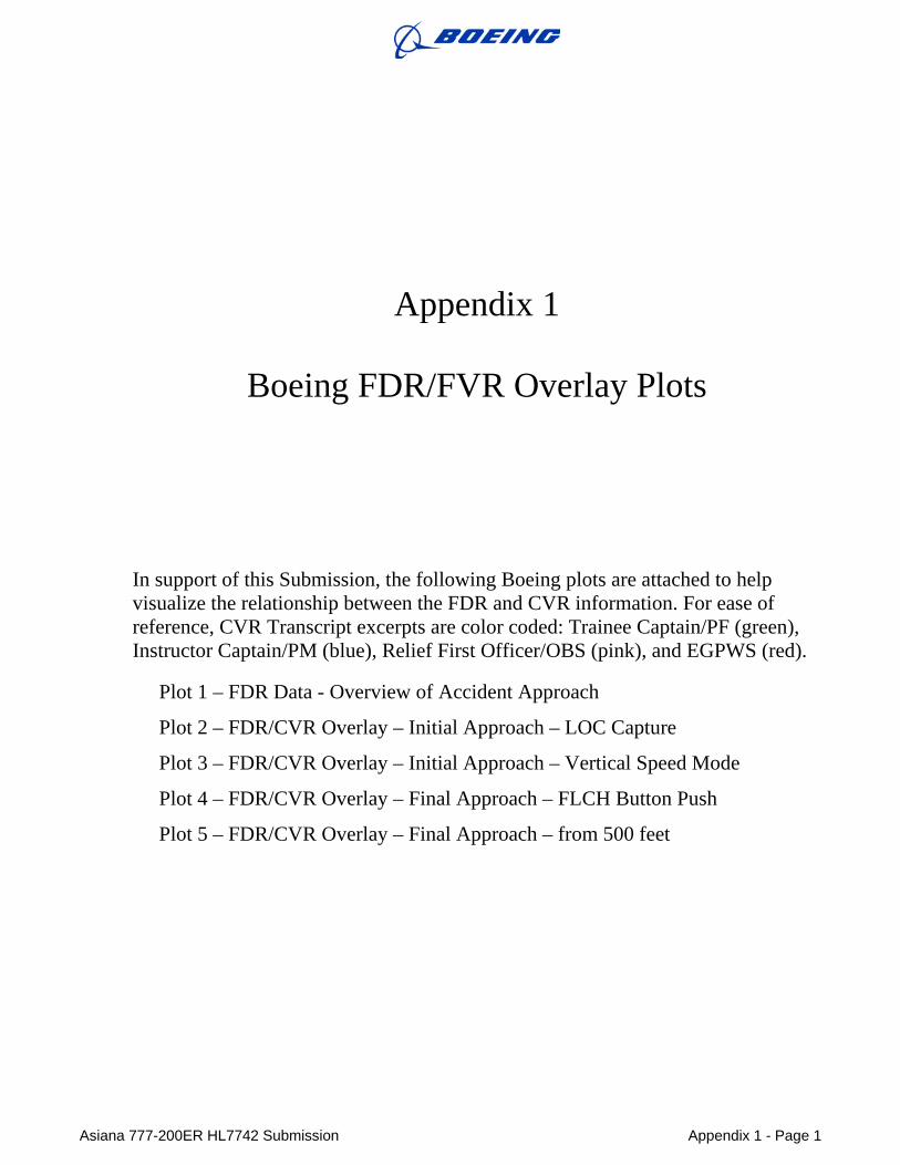
In support of this Submission, the following Boeing plots are attached to help visualize the relationship between the FDR and CVR information. For ease of reference, CVR Transcript excerpts are color coded: Trainee Captain/PF (green), Instructor Captain/PM (blue), Relief First Officer/OBS (pink), and EGPWS (red).
Plot 1 – FDR Data - Overview of Accident Approach
Plot 2 – FDR/CVR Overlay – Initial Approach – LOC Capture
Plot 3 – FDR/CVR Overlay – Initial Approach – Vertical Speed Mode
Plot 4 – FDR/CVR Overlay – Final Approach – FLCH Button Push
Plot 5 – FDR/CVR Overlay – Final Approach – from 500 feet

Asiana 777-200ER H
L7742 Submission
Appendix 1 - Page 2
Plot 1 - FDR
Data
Overview
of Accident A
pproach
Vert
Speed
22
~ 20 (A "'0 ro ro a.
,..... 1'
~ .......,
12
-~:03 -200J 800
T Mode
T hrottl e Le ve r Posn
-1 I I
FOR Data Overview Asiana 777-200 Landing Accident at SFO - 6 July 2013
----, I '-- -.
L ______ §~LS£P------~~._~-~1~cs~~~..-.-~~
600 . - ;· r··········-........ . •••••••. "',Qt.,..
)> rt ;::; 400 c a. ~
·······k~1 <~oo ~ ~h
'I .qo OF(
-iD' ro rt '-'
- 06:00 -05 :00 - 04:00 -03:00 -02: 00 Time to Impact (min :sec)
-01:00
10 ~ ~0 "Tl
20 ~ Q.
30 iii
00 :00
r: ~ ~ ~
Asiana 777-200ER HL7742 Submission Appendix 1 - Page 3
Plot 2 – FDR/CVR Overlay
Initial Approach – LOC Capture
Flap Handle
0 0 0 0 ""' N 1'1 I I I I
CVR Transcript Legend r:~ Q.·~f;!~--~-."R~~!"9.·.r.~~-~~rrit~f~~---~:y:~9.~.~9il
BLACK "' Other Sounds PINK= Observer RED=EGPWS
GREEN = Left Seat Right Seat= BLUE 0 0
ro--~--r----r---rll;-~~--~.---~--~--,dh-e_c_k-rTe_t_,--~----~--~~.:.~~~,-.---,---~--~~--o-.9
flaps five sir 3~Ji'f~eck : d I ~ o.;
J ~ oa. 1,-- - flaps five c eck :::..:f (/)
1 one eight zero
...JI w(J), : ' i c· ·o~fje>C:auiar:S"P:e:eafiaa!.:t1 ···:iiv.e::miia:~:~:4SiaM:ii!i ~
0
r· P..if~·.ASian_'·~-ii:h~GedW:e."Siieeti."~~~- -- ----~~-eiiiJs.·::::. · · !A 9 r-- I . -v
I
I I I
heck flaps orr set
locallz r capture i e) clear vis~al { is giv
'"' u ll1 (/)
c es} y~s sir {I will Set to Me ttl
e did not ~ve H o.S
6 N N
I I I
I I I
I three one zero ID normal {I f'lm 'interc
6 cs 6 6 Ill Ill '0 '0 0 ...-1 0 0'1 (() t-- l: 0
l: N N M M T"i r:. 1-u
Airspeed (kts) '"' ~ ii.
"0 ...... 6 t QJ~ QJ QJil. > a.u.
(/) ......
chec .
:
/
b 6 0 0 0 0 .... N
I I
\0
0 f-r-------.-------r----';;;-..+-11) t
a 0 ro
6 0 0
v N
,a. E
0 M
II)
0 I
0 0 ..
6~ I
0 +-1
Q)
E i=
Al t itude ( feet)
Asiana 777-200ER HL7742 Submission Appendix 1 - Page 4
Plot 3 – FDR/CVR Overlay
Initial Approach – Vertical Speed
Flap Handle
0 0 0 0 .., N "1
I I I I
I
I I I
I • I .
CVR Transcript Legend r:~9.·~~~::~:."R~i!!9. .. t!i~~rrit~f~"ri·.~~:~9.~X9i~
BLACK .. Other Sounds PINK = Observer RED = EGPWS
GRCEN = Left Seat Right Seat= BLUE
housand • •
. ,.a:;AS~B· ··:f14:itea.Vii:coi:iiact:sF. iO:wer::t2cf5J
0 a. (/)
..J w (/)
.. :::: .. ....... : ...... , ...... jncrease.d.ba
yea
6 6 6 cs 6 6 0 C7\ co " ~ 11'1 N .-I .-1 .-I .-I .-1
Airspeed (kt s) .t:. u ... ii:
I will d scend more
mean ', 's too high?
yeah DJ.Jnd.nf lse okay g ar down sir
I I
I I I
I I I
~J
this hould be a bit high
bhJ~ 88W~ a little high :it: J: .... ~ 8 /~ .... ~~ f
.I P f ive ~~ight z o / :
Me e1. .te"'\?jflll ~%'h ah one eight .• :~(o o one eight ~ero fi e m 1les
Ill check 6 '0 set 0 flagsJv~ 0 z
1-sp e c ~
Ill ~
6 6 6 0 0 0 0 0 0 "it M N
t 1J ..... 6 C!) 6 Q)~ 0 0 Q) Q)Q. 0 0 > a.u. ~ N Vl'-' I I
Altitude ( fee t)
0
0 M
N 0
-u Cll VI ..
3::1 CI)>O 1:
0 o.S ..t:::
~ "" ~ ~ q, 0 c: .!!! c5
0 Mt) o ro 10..
E 0
~0 .
0
0 M
M 0
I
0 0
~ 6g ' 0 I
0 .-I
""" 0 +J
Cll E i=
Asiana 777-200ER HL7742 Submission Appendix 1 - Page 5
Plot 4 – FDR/CVR Overlay
Final Approach – FLCH Button Push
Flap Handle
0 0 0 0 .., N "1
I I I I
6 6 6 0 co 1.0 N ""' 1""1
cs 6 v N 1""1 '"" Airs peed ( kts)
6 0 1""1
CVR Transcript Legend r:~9.-~~~::~:."R~i!!9. .. t!i~~rrit~f~"ri·.~~:~9.~X9i~
BLACK .. Other Sounds PINK= Observer RED = EGPWS
GRCEN = Left Seat Right Seat= BLUE
l yeah
fl ps (twenty)
t 1J ..... 6 Q)~
Q) Q)Q. > a.u.
Vl'-'
6 0 0 v
C!) 6 0 0 0 0 ~ N
I I
6 6 6 0 0 0 0 0 0 M N .-4
Altitude (feet)
0 0
~ 0 ~ 0
I
-u Cll VI
1:
o.S ""' '""t) o ro 10..
E
Ln v
""' 0 I
0 N
6~ I
0 +J
Cll E i=
Asiana 777-200ER HL7742 Submission Appendix 1 - Page 6
Plot 5 – FDR/CVR OverlayFinal Approach from 500 feet
6 v .-1
t I
I t I
I t I
I IO IQ. Ill) I ...I lw
1/)
(5 6 (5 M N .-1 .-1 .-1 .-1
Air speed (kts)
rfJ--BDEING
CVR Transcript Legend r:~o.-~!i$!:~·:R~~-f9.·.r.~~-~-~m!~.~i9.i:i:.~Y:[email protected]
BLACK = Other Sounds PINK :: Observer RED = EGPWS
GREEN = Left Seat Right Seat = BLUE 1'\1 .... I
Column Posn {deg) P1tch Angle {deg)
0 .... f t(l v I I I
·········
N I
· .. :·~
:::
o o I a ..
0 0
0 ..... 0 0
-u v VI
c:
o.S N.u .. u Oro Oa.
I E
0 M
0 0
I
0 ,jJ
v E i=
····························································1 ...
I j
. . ·, :·.Rno.::f·i;laaca<i"Ji> .
6 6 (!) 0 0 0 .-1 IJ'l v
6t u.-..(!) (!; Ql I: o 0 Ql Ql Q. Ill 0 > Q. U. I .... (/) ........
6 0 Ill ....
I
6 (5 0 0 N ...,.
Altitude (fe et)
···.
Asiana 777-200ER HL7742 Submission Appendix 2 - Page 1
Appendix 2
777 Flight Deck Description
The following additional information is provided in support of this Submission. The discussion below provides information relative to issues that have arisen or been discussed during the course of the investigation. Each section contains a description of the item, followed by a discussion on how the item applies to the accident data. This Appendix contains the following:
• 777 FLIGHT DECK DESIGN APPROACH o Backdriven and Interlinked Controls o Airspeed Cues
• AUTOMATION PHILOSOPHY
• AUTOTHROTTLE MODES and OPERATION
o Autothrottle Hold Mode o Automatic Autothrottle Engage Feature
Demonstration to FAA in 1995 during 777 Certification Trainee Captain’s Transition Training
• CENTRALIZED CREW ALERTING (EICAS)
Asiana 777-200ER HL7742 Submission Appendix 2 - Page 2
777 FLIGHT DECK DESIGN APPROACH In designing the 777 flight deck, Boeing employed a human-centered design approach that envisioned the crew as an integral element of the aircraft with final authority over its operation.66
As part of this approach, Boeing drew on the knowledge and experience of a wide range of outside experts, including pilots from customer airlines, representatives from pilots’ unions, regulators, and human factors experts from industry, academia and government.67 Outside experts were involved in every stage of the 777 flight deck’s design and development, from the initial engineering design meetings to simulator and flight testing.68 Input received from these experts was combined with the knowledge and experience that Boeing engineers, human factors experts and test pilots have developed over decades of designing aircraft. The design evolved from the 757/767 flight deck design to incorporate new technologies, new operational requirements, and lessons learned from millions of hours of in-service experience.
Backdriven And Interlinked Controls To support the pilot’s ability to monitor the aircraft during automated or manual flight, Boeing provides visual and tactile cues through interlinked, large displacement, backdriven controls. “Interlinked” means that as one of the pilots moves the control column, control wheel or rudder pedals during manual flight, the column, wheel and pedals in front of the other pilot also move in unison, which allows the pilot monitoring to feel what the pilot flying is doing. Large displacement describes the large range of motion of the control column and control wheel, which allows the pilot monitoring to be fully aware of the flying pilot’s control inputs. “Backdriven” means that all the controls move when the autopilot or autothrottle is controlling the airplane. This allows the pilots and the observers to monitor and follow the control inputs of the autopilot or autothrottle.69 As the autothrottle positions the throttles, an audible motoring noise is heard. This design approach allows both pilots and the observers to easily and continuously remain in the loop.
During the accident approach, the PF stated that he had his hand on the throttle levers and therefore should have felt that the autothrottle was not moving the throttle levers to control speed. All three pilots could have seen that the throttle levers were at idle stops, which is not the correct thrust setting for approach.70
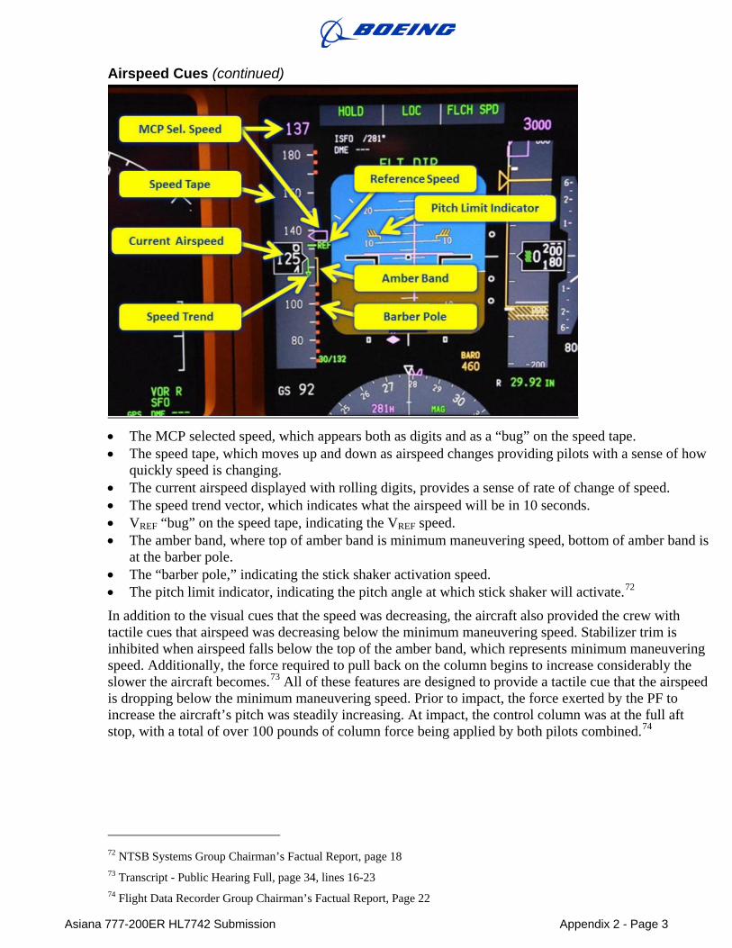
Airspeed Cues Critical flight parameters like airspeed, altitude, attitude and heading were located on the primary flight display, which is in the pilots’ primary field of view. The accident aircraft provided numerous visual cues to the crew that their airspeed was decreasing below the target speed for landing. As shown in the picture of the PFD below,71 these cues included:
66 Transcript - Public Hearing Full, page 167 lines 4-5; Human Performance Group Chairman’s Factual Report, Exhibit 14-D, Page 3 67 Transcript - Public Hearing Full, Page 29, lines 9-20; Page 171, lines 13-22; Pages 64-65, lines13 -2; pages 167-68, lines 3-2 68 Transcript - Public Hearing Full, Pages 64-65, lines13 -2 69 NTSB Human Performance Group Chairman’s Factual Report, Exhibit 14-D, Page 12 70 NTSB Operations Group Chairman’s Factual Report, Exhibit 02-B, page 14, 20, 39 71 Human Performance Group Chairman’s Factual Report, Exhibit 14-D, Page 8
Asiana 777-200ER HL7742 Submission Appendix 2 - Page 3
Airspeed Cues (continued)
• The MCP selected speed, which appears both as digits and as a “bug” on the speed tape. • The speed tape, which moves up and down as airspeed changes providing pilots with a sense of how
quickly speed is changing. • The current airspeed displayed with rolling digits, provides a sense of rate of change of speed. • The speed trend vector, which indicates what the airspeed will be in 10 seconds. • VREF “bug” on the speed tape, indicating the VREF speed. • The amber band, where top of amber band is minimum maneuvering speed, bottom of amber band is
at the barber pole. • The “barber pole,” indicating the stick shaker activation speed. • The pitch limit indicator, indicating the pitch angle at which stick shaker will activate.72 In addition to the visual cues that the speed was decreasing, the aircraft also provided the crew with tactile cues that airspeed was decreasing below the minimum maneuvering speed. Stabilizer trim is inhibited when airspeed falls below the top of the amber band, which represents minimum maneuvering speed. Additionally, the force required to pull back on the column begins to increase considerably the slower the aircraft becomes.73 All of these features are designed to provide a tactile cue that the airspeed is dropping below the minimum maneuvering speed. Prior to impact, the force exerted by the PF to increase the aircraft’s pitch was steadily increasing. At impact, the control column was at the full aft stop, with a total of over 100 pounds of column force being applied by both pilots combined.74
72 NTSB Systems Group Chairman’s Factual Report, page 18 73 Transcript - Public Hearing Full, page 34, lines 16-23 74 Flight Data Recorder Group Chairman’s Factual Report, Page 22
Asiana 777-200ER HL7742 Submission Appendix 2 - Page 4
AUTOMATION PHILOSOPHY One high level Boeing design philosophy is that the pilot always has the final authority over any automation system utilized for flight. This philosophy requires the flight crew to monitor the automation and intervene in the case where an automated system does not perform as expected. As such, there are clear indicators built into the autoflight system that make it easy for the crew to always be aware of their situation. Selected autopilot and autothrottle modes are indicated on the MCP via lighted buttons, and the active modes are clearly displayed to both flight crew members via the FMA located on the same Primary Flight Display panel where altitude, airspeed and airplane attitude are indicated. Additionally, backdriven controls show the pilots how the autoflight system is flying the airplane. If either pilot is uncomfortable with the automatic operation, he or she can either override the controls or disconnect some or all of the autoflight system. In either case, the autoflight system is designed to gracefully cede control to the pilots.
AUTOTHROTTLE MODES and OPERATION The autothrottle can be set by the crew to automatically control thrust. With both in use, the AFDS and Autothrottle work together to accomplish the commanded task. When a MCP pitch mode selection is made, the AFDS first engages its mode, and then the Autothrottle engages in a mode that correctly pairs with the AFDS pitch mode.
For example, when the active AFDS pitch mode is altitude hold (ALT), in which the AFDS maintains a selected altitude, or V/S, in which the AFDS maintains a selected vertical speed, the autothrottle will pair in the SPD mode. In these configurations, airspeed is controlled by the autothrottle, and the AFDS uses pitch commands to control altitude or vertical speed, respectively. These are examples of “speed-on-throttle” modes. It is important to note that the only time the autothrottle controls airspeed is when the active autothrottle mode is speed (SPD). If any other autothrottle mode is active, the autothrottle is not controlling airspeed.
Alternatively, when the active AFDS pitch mode is FLCH SPD or VNAV SPD, airspeed is not controlled by the autothrottle, but instead is controlled by the AFDS pitch command. These are ‘speed-on-elevator’ modes, where the AFDS is controlling airspeed using pitch commands. In these modes, the autothrottle simply increases or decreases thrust to achieve a certain climb or descent rate.
If the crew has activated the flight director but is not following its guidance, the normal or expected autoflight performance will have been overridden. For example, if the crew is using the flight directors in FLCH SPD mode to accomplish a descent, the flight director will command a nose-down descent to maintain airspeed and the autothrottle will either be in THR or HOLD. If the crew were to manually level off and not follow the flight director commands, the crew has overridden the autoflight system and it will no longer be controlling airspeed. It is the responsibility of the pilot to maintain the required airspeed in this situation because the pilot has overridden the autoflight system. Further, the Boeing FCTM recommends that if the flight director commands are not being followed, they should be turned off.75
Even in a situation where the flight director guidance is being followed, the entire crew always has the responsibility to monitor course, path, and airspeed, and to intervene if the autoflight system is not performing as expected.
75 Boeing FCTM, page 1.34
Asiana 777-200ER HL7742 Submission Appendix 2 - Page 5
Autothrottle Hold Mode When using Flight Level Change (FLCH SPD), the autothrottle, if armed, will enter the thrust mode (THR) and adjust thrust to a level that will achieve the commanded change in altitude over about a two minute period, if possible. The pilot can alter this two minute period by manually changing thrust, without having to disconnect the autothrottle. For example, if a FLCH SPD climb is commanded the airplane will begin to climb. The pilot can increase thrust to achieve the climb faster (in less than 2 minutes), or decrease thrust to achieve the climb more slowly (in more than 2 minutes). When this manual override occurs, the Autothrottle goes into HOLD mode, which acknowledges that the throttles are being controlled by the pilot. This mode change is annunciated on the FMAs and surrounded by a green box for 10 seconds to emphasize it.
The HOLD mode in FLCH SPD is used in other situations as well, but any time HOLD is annunciated on the primary flight displays, the autothrottle servos are unpowered and the autothrottle is not controlling thrust or airspeed. As stated in Boeing’s manuals, when the HOLD mode is engaged, “the thrust lever autothrottle servos are inhibited. The pilot can set thrust levers manually.” Boeing manuals further explain that “… the autothrottle system does not reposition thrust levers while in HOLD mode.”76
The HOLD mode is not unique or new on the 777; it has been used successfully by thousands of pilots since 1982 in 757, 767, 747-400, 777 and 787 model aircraft.77 In total, aircraft equipped with an autoflight system that uses these same FLCH SPD and HOLD modes have performed 55.6 million successful landings, which equates to more than three landings a minute, every minute of every day for the last 32 years.
HOLD mode is only used in conjunction with AFDS speed-on-elevator modes (e.g. FLCH SPD, Vertical Navigation Speed [VNAV SPD]). When the autothrottle is in SPD mode, the pilot can still manually override the throttles, but the autothrottle will remain in SPD (i.e. will not go into HOLD) and will again move the throttle levers after the pilot releases them.
Automatic Autothrottle Engage Feature The automatic autothrottle engage feature, sometimes referred to as the autothrottle “wake-up” feature, activates the autothrottle if certain conditions are met. It has the same function as if the crew presses the autothrottle engage button, activating the autothrottle. This action, either pushing the autothrottle engage button or the automatic engage feature, activates the autothrottle only if the autothrottle has not already been activated by the crew. Therefore, if the autothrottle is already in a mode that was activated by crew action, such as the HOLD mode, then the automatic autothrottle engage feature has no function to perform because the autothrottle is already engaged.
During the accident approach, the autothrottle did not activate when the speed decayed because the autothrottle was already engaged and in the HOLD mode.
During the investigation, Boeing was asked why the autothrottle does not automatically transition from HOLD mode to SPD mode at some low speed to avoid a stall. To do this would
76 Boeing FCOM, page 4.20.10 77 Human Performance 14 - Exhibit 14D - Boeing Material Requested by NTSB, page 16
Asiana 777-200ER HL7742 Submission Appendix 2 - Page 6
violate the aforementioned design philosophy: the pilot is the final authority for the operation of the airplane.78 This philosophy has led Boeing to avoid designs in which the aircraft overrides the crew’s selected automation modes. If the autothrottle automatically switched from HOLD to SPD mode, it would be overriding the crew’s selection of the HOLD mode. There are some scenarios, such as when the aircraft is operating in an asymmetric thrust condition due to engine problems, in which such a change could be potentially dangerous.79
Further, having the autothrottle transition to SPD mode while the AFDS is in FLCH SPD would create a situation with two automatic systems attempting to control airspeed, which is potentially unstable. Boeing believes the current design of the autothrottle HOLD feature is entirely appropriate given the wide range of scenarios for which it was developed.
Autothrottle Automatic Engage Feature - Demonstration to FAA As Boeing’s manuals state: “…when the pitch mode is FLCH…the autothrottle will not automatically activate.”80 Boeing demonstrated this aspect of the automatic autothrottle engage feature to the FAA on a 777 certification flight in 1995. The certification flight included an FAA pilot and an FAA engineer, and specifically demonstrated that the autothrottle did not automatically engage if the autopilot was in FLCH. The Flight Test Certification Report that documented this flight states: “Per design, when the autopilot is controlling airspeed, the autothrottle automatic engage feature is disabled.” The FAA approved that report on 27 May 1996. After conducting the test and reviewing and approving the certification report, the FAA found that the system met certification standards and was safe. This was also discussed in the NTSB Hearing.81
Automatic Autothrottle Engage Feature – Trainee Captain’s Transition Training The Trainee Captain’s transition training course included specific instruction on the fact that in a Flight Level Change (FLCH SPD) descent, the 777 autothrottle may transition to HOLD mode and will not automatically activate if speed decays, including specific instruction on how this would occur in an approach to SFO. The Trainee Captain received this instruction during two ground school transition training classes (“Flight Control” and “Performance”).5 In both classes this characteristic of the autoflight system was discussed in the context of an approach to SFO.82
78 Transcript - Public Hearing Full, page 47, lines 20-23 79 Transcript - Public Hearing Full, pages 60, lines 13-16, pages 60-61, lines 22-1 80 NTSB Operations Group Chairman’s Factual Report dated 15 Nov.2013, page 28. 81 Transcript - Public Hearing Full, page 57, lines 18-23. 82 NTSB Operations Group Chairman’s Factual Report, Exhibit 02-D, pages 8-9, 16-17
Asiana 777-200ER HL7742 Submission Appendix 2 - Page 7
CENTRALIZED CREW ALERTING The Engine Indicating and Crew Alerting System (EICAS) provides the flight crew with a centralized location83 to view all alerts. EICAS alerts are grouped into three priority levels: Warning, Caution and Advisory. Warnings alert the crew to non-normal operational conditions requiring immediate crew awareness and action. They are annunciated through the Master Warning lights and a continuous aural siren, with a message displayed in red on the EICAS display, which is located on the center of main instrument panel between the two pilots. Cautions alert the crew to non-normal operational or system conditions requiring immediate crew awareness. Corrective action may be required. They are annunciated through the Master Caution lights and a beeper, with a message displayed in amber on the EICAS display. Advisories alert the crew to non-normal operational or system conditions requiring routine crew awareness. Corrective action may be required. A message is displayed in amber on the EICAS display.84 There is no aural alert associated with an Advisory message.
The EICAS design, which originated during the development of the Boeing 757 and 767 models, minimizes the number of different alerts and the distribution of alerts throughout the cockpit; minimizes pilot task saturation and confusion; provides for consistent classification of alerts relative to procedures; and provides for consistent application of color, flashing lights and aural alerts. As part of the EICAS design process Boeing conducted testing and analysis to confirm the effectiveness of various aspects of the alerts, including sound type, sound level, and sound detectability and distinguishability. The entire EICAS system was also the subject of extensive simulator testing. Alert sound detection and recognition time were measured under varied conditions of pilot workload, pre-existing alerts, normal versus failed alerting sounds, and alert category. The FAA has recognized EICAS as an effective form of alerting, certifying the design on the Boeing 747-400, 747-8, 757, 767, 777 and 787 models. Further, in 2010 the FAA revised Federal Aviation Regulation 25.1322, “Flight Crew Alerting,” to largely adopt the EICAS alerting philosophy regarding alert hierarchy and colors.85
While voice alerts are also a safe method for alerting flight crews to a low airspeed condition, the EICAS system has numerous benefits. For example, non-English speaking flight crews may have more difficulty understanding spoken English than written English. The EICAS warning remains on the screen, allowing the pilots to view and review the message, whereas voice alert is quickly gone. Further, only one voice alert is possible at a time, meaning that another voice alert may take priority, and voice alerts may disrupt other voice communications.
The EICAS design has been recognized as an effective method for alerting a flight crew to a low airspeed condition. In 2010 the FAA assigned the Aviation Rulemaking Advisory Committee the task of identifying and developing recommendations for additional requirements for low airspeed alerting in new transport category airplanes. After analyzing existing low airspeed alerting systems, the Avionics Systems Harmonization Working Group concluded that the EICAS design provides a timely alert to flight crews of a potentially adverse airspeed situation.86
83 Human Performance 14 - Exhibit 14D - Boeing Material Requested by NTSB, page 17 84 Boeing FCOM 15.20.1-2 85 14 C.F.R. § 25.1322 86 Avionics Systems Harmonization Working Group (ASHWG) Low Airspeed Alerting (LAA)
Report Phase 2, Rev A, page. 8-10