MHT Vane Motors - Eatonpub/@eaton/@hyd/documents/co… · 1 Introduction Vickers MHT vane motors...
37
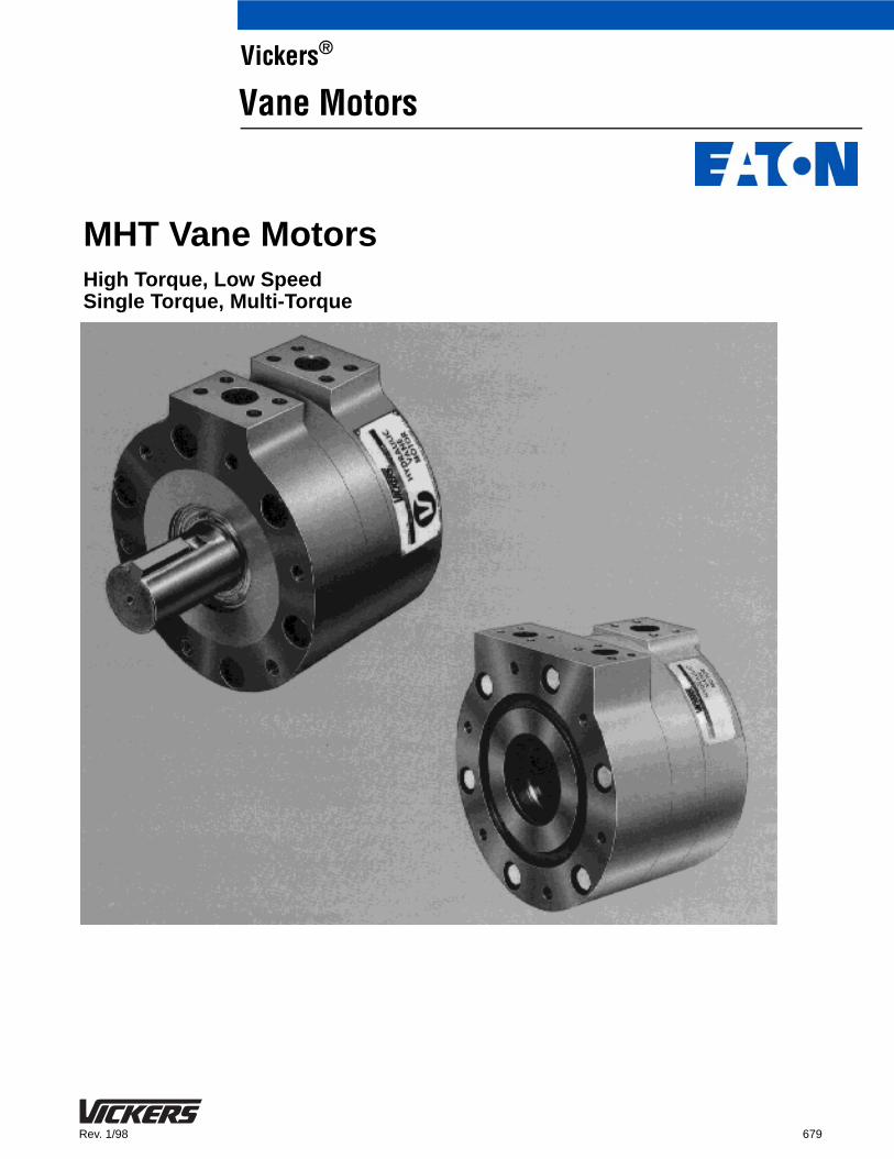
679 Rev. 1/98 MHT Vane Motors High Torque, Low Speed Single Torque, Multi-Torque Vickers ® Vane Motors
Transcript of MHT Vane Motors - Eatonpub/@eaton/@hyd/documents/co… · 1 Introduction Vickers MHT vane motors...
679Rev. 1/98
MHT Vane MotorsHigh Torque, Low SpeedSingle Torque, Multi-Torque
Vickers®
Vane Motors

Vickers, Incorporated 1994All Rights Reserved

1
Introduction
Vickers MHT vane motors are theefficient, economical answer to a widerange of power needs. Thesehigh-quality motors are the ideal choicewhen:
� the combination of high torque and low speed is required
� a high power-to-weight/size ratio is required
� hazardous conditions or other design factors make it desirable that the electrical prime power source be located some distance away from themachinery driving motor.
Applications
MHT motors can be used in a widevariety of industrial and mobileapplications, for example:
� Continuous casting machines
� Straightener drives
� Wheel rim rolling machines
� Forging manipulators
� Winding machine drives
� Sheet line accumulator systems
� Pre-plasticizer drives
� Machine tool spindle drives
� Coil winders
� Conveyors
� Feeder screws
� Rolling mill screwdown drives
� Drilling, boring machines
� Crushers
Features and Benefits
� Available in shaft-type or shaftless. Shaftless MHT motors can simplify installations, since the driven machine’s splined shaft can be drivendirectly by the motor. Shaft-to-shaft couplings are thereby eliminated.
� MHT motors provide variable power throughout their entire pressure and speed range, and perform smoothly and efficiently in either direction of rotation.
� Shaftless MHT motors permit cooling water to be run through a hollow driving shaft, for example, driving plastic injection molding and extruder screws.
� Long operating life
� Stepless, infinitely variable speed control.
� Quick shaft reversing by reversing fluid flow.
Standard Motors
Vickers standard MHT motors are idealfor rotary power apllications requiringhigh torque at low speed. They providevariable power throughout their entirepressure and speed range, and performefficiently and smoothly in eitherdirection of rotation.
Because these motors can eliminate theneed for gear boxes or other externalspeed reducing devices, they offer theadded advantage of compactness.
Multi-Torque Series
The Vickers multi-torque MHT motor issimilar to the standard MHT motor inapplication and performance benefits,with one major difference – the design ofthe multi-torque motor permits choosinga number of different speed and torquecombinations for any given flow andpressure.
For example, under conditions wheremaximum torque is not required, topmotor speed can be achieved using thepartial torque circuit shown. Conversely,maximum torque could also be achievedat less than maximum motor speed,using the full torque circuit shown.
This versatility permits substantialsavings in pump size and costs formany applications without sacrificingnecessary torque or speedcharacteristics.
� MHT multi-torque motors offer the ability to change the torque-to-speed ratios without requiring gear shifting mechanisms.
1
Contents
Ratings 2. . . . . . . . . . . . . . . . . . . . . . . . . . . . . . . . . . . . . . . . . . . . . . . . . . . . . . . . . . . . . . . . . . . . . . . . . . . . . . . . . . . . . . . . . . . . . . . . . . . . . . .
Single Torque, Single Displacement Models 2. . . . . . . . . . . . . . . . . . . . . . . . . . . . . . . . . . . . . . . . . . . . . . . . . . . . . . . . . . . . . . . . . . . . .
Multi-Torque, Multi-Displacement Models 3. . . . . . . . . . . . . . . . . . . . . . . . . . . . . . . . . . . . . . . . . . . . . . . . . . . . . . . . . . . . . . . . . . . . . . .
Model Code 4. . . . . . . . . . . . . . . . . . . . . . . . . . . . . . . . . . . . . . . . . . . . . . . . . . . . . . . . . . . . . . . . . . . . . . . . . . . . . . . . . . . . . . . . . . . . . . . . . . .
Installation Data 5. . . . . . . . . . . . . . . . . . . . . . . . . . . . . . . . . . . . . . . . . . . . . . . . . . . . . . . . . . . . . . . . . . . . . . . . . . . . . . . . . . . . . . . . . . . . . . .
Mounting Information 5. . . . . . . . . . . . . . . . . . . . . . . . . . . . . . . . . . . . . . . . . . . . . . . . . . . . . . . . . . . . . . . . . . . . . . . . . . . . . . . . . . . . . . . .
Circuit 6. . . . . . . . . . . . . . . . . . . . . . . . . . . . . . . . . . . . . . . . . . . . . . . . . . . . . . . . . . . . . . . . . . . . . . . . . . . . . . . . . . . . . . . . . . . . . . . . . . . . .
Shaft Information 7. . . . . . . . . . . . . . . . . . . . . . . . . . . . . . . . . . . . . . . . . . . . . . . . . . . . . . . . . . . . . . . . . . . . . . . . . . . . . . . . . . . . . . . . . . . .
Application Data 8. . . . . . . . . . . . . . . . . . . . . . . . . . . . . . . . . . . . . . . . . . . . . . . . . . . . . . . . . . . . . . . . . . . . . . . . . . . . . . . . . . . . . . . . . . . . . .
Start-up Procedure 8. . . . . . . . . . . . . . . . . . . . . . . . . . . . . . . . . . . . . . . . . . . . . . . . . . . . . . . . . . . . . . . . . . . . . . . . . . . . . . . . . . . . . . . . . .
Functional Symbols 8. . . . . . . . . . . . . . . . . . . . . . . . . . . . . . . . . . . . . . . . . . . . . . . . . . . . . . . . . . . . . . . . . . . . . . . . . . . . . . . . . . . . . . . . . .
Rotation 9. . . . . . . . . . . . . . . . . . . . . . . . . . . . . . . . . . . . . . . . . . . . . . . . . . . . . . . . . . . . . . . . . . . . . . . . . . . . . . . . . . . . . . . . . . . . . . . . . . .
Bearing Capacity 9. . . . . . . . . . . . . . . . . . . . . . . . . . . . . . . . . . . . . . . . . . . . . . . . . . . . . . . . . . . . . . . . . . . . . . . . . . . . . . . . . . . . . . . . . . . .
Inertia of Rotating Group 9. . . . . . . . . . . . . . . . . . . . . . . . . . . . . . . . . . . . . . . . . . . . . . . . . . . . . . . . . . . . . . . . . . . . . . . . . . . . . . . . . . . . .
Performance Data 11. . . . . . . . . . . . . . . . . . . . . . . . . . . . . . . . . . . . . . . . . . . . . . . . . . . . . . . . . . . . . . . . . . . . . . . . . . . . . . . . . . . . . . . . . . . .
MHT32 11. . . . . . . . . . . . . . . . . . . . . . . . . . . . . . . . . . . . . . . . . . . . . . . . . . . . . . . . . . . . . . . . . . . . . . . . . . . . . . . . . . . . . . . . . . . . . . . . . . .
MHT50 11. . . . . . . . . . . . . . . . . . . . . . . . . . . . . . . . . . . . . . . . . . . . . . . . . . . . . . . . . . . . . . . . . . . . . . . . . . . . . . . . . . . . . . . . . . . . . . . . . . .
MHT70 and MHT90 12. . . . . . . . . . . . . . . . . . . . . . . . . . . . . . . . . . . . . . . . . . . . . . . . . . . . . . . . . . . . . . . . . . . . . . . . . . . . . . . . . . . . . . . .
MHT130 and MHT150 12. . . . . . . . . . . . . . . . . . . . . . . . . . . . . . . . . . . . . . . . . . . . . . . . . . . . . . . . . . . . . . . . . . . . . . . . . . . . . . . . . . . . . .
MHT150 13. . . . . . . . . . . . . . . . . . . . . . . . . . . . . . . . . . . . . . . . . . . . . . . . . . . . . . . . . . . . . . . . . . . . . . . . . . . . . . . . . . . . . . . . . . . . . . . . . .
MHT250 14. . . . . . . . . . . . . . . . . . . . . . . . . . . . . . . . . . . . . . . . . . . . . . . . . . . . . . . . . . . . . . . . . . . . . . . . . . . . . . . . . . . . . . . . . . . . . . . . . .
MHT500 15. . . . . . . . . . . . . . . . . . . . . . . . . . . . . . . . . . . . . . . . . . . . . . . . . . . . . . . . . . . . . . . . . . . . . . . . . . . . . . . . . . . . . . . . . . . . . . . . . .
MHT750 16. . . . . . . . . . . . . . . . . . . . . . . . . . . . . . . . . . . . . . . . . . . . . . . . . . . . . . . . . . . . . . . . . . . . . . . . . . . . . . . . . . . . . . . . . . . . . . . . . .
MHT1000 16. . . . . . . . . . . . . . . . . . . . . . . . . . . . . . . . . . . . . . . . . . . . . . . . . . . . . . . . . . . . . . . . . . . . . . . . . . . . . . . . . . . . . . . . . . . . . . . . .
MHT90/45/45 17. . . . . . . . . . . . . . . . . . . . . . . . . . . . . . . . . . . . . . . . . . . . . . . . . . . . . . . . . . . . . . . . . . . . . . . . . . . . . . . . . . . . . . . . . . . . . .
MHT380/190/190 18. . . . . . . . . . . . . . . . . . . . . . . . . . . . . . . . . . . . . . . . . . . . . . . . . . . . . . . . . . . . . . . . . . . . . . . . . . . . . . . . . . . . . . . . . . .
MHT440/250/190 18. . . . . . . . . . . . . . . . . . . . . . . . . . . . . . . . . . . . . . . . . . . . . . . . . . . . . . . . . . . . . . . . . . . . . . . . . . . . . . . . . . . . . . . . . . .
MHT500/250/250 19. . . . . . . . . . . . . . . . . . . . . . . . . . . . . . . . . . . . . . . . . . . . . . . . . . . . . . . . . . . . . . . . . . . . . . . . . . . . . . . . . . . . . . . . . . .
Installation Dimensions – Single Torque Models
MHT 32 20. . . . . . . . . . . . . . . . . . . . . . . . . . . . . . . . . . . . . . . . . . . . . . . . . . . . . . . . . . . . . . . . . . . . . . . . . . . . . . . . . . . . . . . . . . . . . . . . . . .
MHT 50 21. . . . . . . . . . . . . . . . . . . . . . . . . . . . . . . . . . . . . . . . . . . . . . . . . . . . . . . . . . . . . . . . . . . . . . . . . . . . . . . . . . . . . . . . . . . . . . . . . . .
MHT 70 & MHT 90 22. . . . . . . . . . . . . . . . . . . . . . . . . . . . . . . . . . . . . . . . . . . . . . . . . . . . . . . . . . . . . . . . . . . . . . . . . . . . . . . . . . . . . . . . .
MHT 130 & MHT 150 23. . . . . . . . . . . . . . . . . . . . . . . . . . . . . . . . . . . . . . . . . . . . . . . . . . . . . . . . . . . . . . . . . . . . . . . . . . . . . . . . . . . . . . .
MHT 190 & MHT 220 & MHT 250 24. . . . . . . . . . . . . . . . . . . . . . . . . . . . . . . . . . . . . . . . . . . . . . . . . . . . . . . . . . . . . . . . . . . . . . . . . . . . .
MHT 380 & MHT 440 & MHT 500 25. . . . . . . . . . . . . . . . . . . . . . . . . . . . . . . . . . . . . . . . . . . . . . . . . . . . . . . . . . . . . . . . . . . . . . . . . . . . .
MHT 750 26. . . . . . . . . . . . . . . . . . . . . . . . . . . . . . . . . . . . . . . . . . . . . . . . . . . . . . . . . . . . . . . . . . . . . . . . . . . . . . . . . . . . . . . . . . . . . . . . . .
MHT 1000 27. . . . . . . . . . . . . . . . . . . . . . . . . . . . . . . . . . . . . . . . . . . . . . . . . . . . . . . . . . . . . . . . . . . . . . . . . . . . . . . . . . . . . . . . . . . . . . . . .
Installation Dimensions – Multi-Torque Models
MHT 70/35/35 & MHT 90/45/45 28. . . . . . . . . . . . . . . . . . . . . . . . . . . . . . . . . . . . . . . . . . . . . . . . . . . . . . . . . . . . . . . . . . . . . . . . . . . . . .
MHT 130/75/75 & MHT 150/75/75 29. . . . . . . . . . . . . . . . . . . . . . . . . . . . . . . . . . . . . . . . . . . . . . . . . . . . . . . . . . . . . . . . . . . . . . . . . . . .
MHT 250/125/125 & 250/125/95 & 190/95/95 30. . . . . . . . . . . . . . . . . . . . . . . . . . . . . . . . . . . . . . . . . . . . . . . . . . . . . . . . . . . . . . . . . .
MHT 380/190/190 & 440/250/190 & 500/250/250 31. . . . . . . . . . . . . . . . . . . . . . . . . . . . . . . . . . . . . . . . . . . . . . . . . . . . . . . . . . . . . . .
MHT 750/375/375 32. . . . . . . . . . . . . . . . . . . . . . . . . . . . . . . . . . . . . . . . . . . . . . . . . . . . . . . . . . . . . . . . . . . . . . . . . . . . . . . . . . . . . . . . . .
MHT 1000/500/500 33. . . . . . . . . . . . . . . . . . . . . . . . . . . . . . . . . . . . . . . . . . . . . . . . . . . . . . . . . . . . . . . . . . . . . . . . . . . . . . . . . . . . . . . . .
Fluid Information 34. . . . . . . . . . . . . . . . . . . . . . . . . . . . . . . . . . . . . . . . . . . . . . . . . . . . . . . . . . . . . . . . . . . . . . . . . . . . . . . . . . . . . . . . . . . . .
2
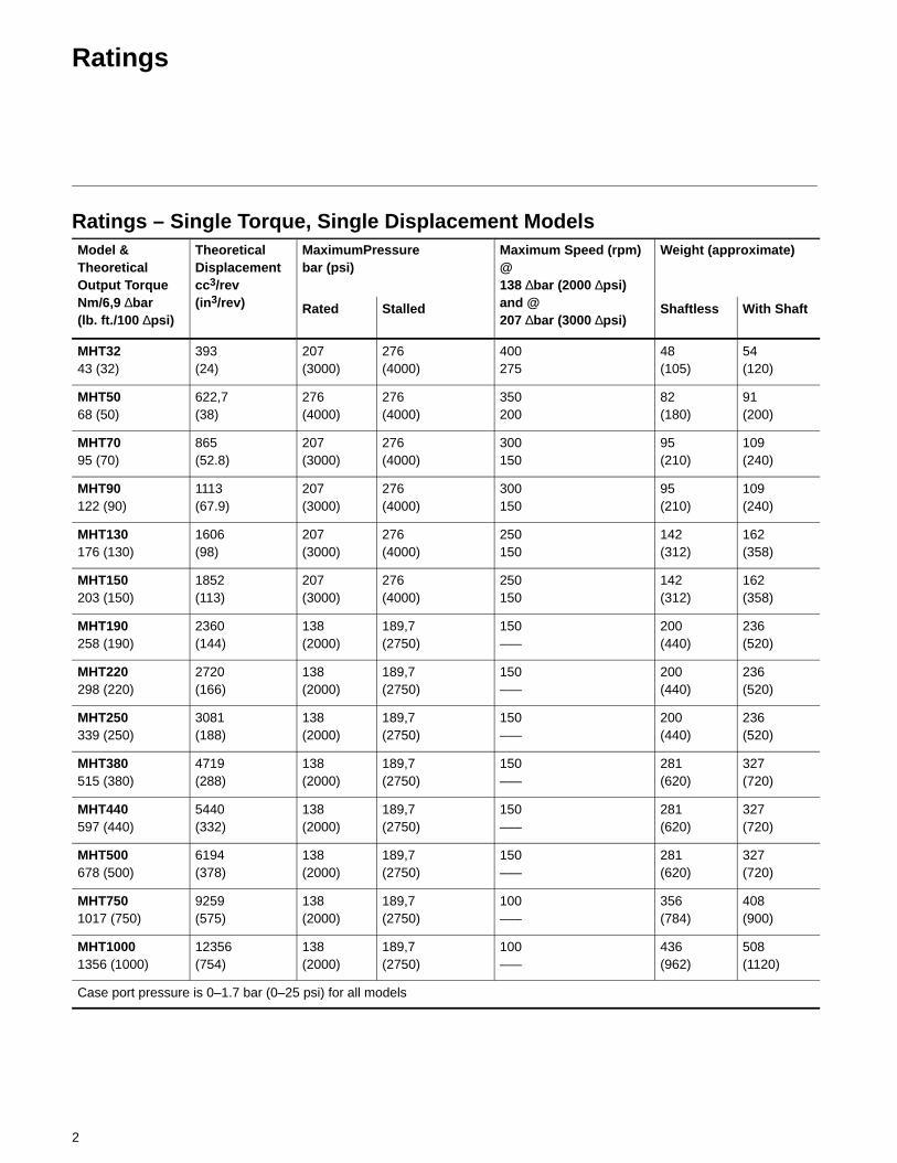
Ratings
Ratings – Single Torque, Single Displacement ModelsModel &TheoreticalOutput Torque
TheoreticalDisplacementcc3/rev
3
MaximumPressurebar (psi)
Maximum Speed (rpm)@138 ∆bar (2000 ∆psi)
Weight (approximate)
p qNm/6,9 ∆bar(lb. ft./100 ∆psi)
(in3/rev) Rated Stalled
( p )and @207 ∆bar (3000 ∆psi)
Shaftless With Shaft
MHT3243 (32)
393(24)
207(3000)
276(4000)
400275
48(105)
54(120)
MHT5068 (50)
622,7(38)
276(4000)
276(4000)
350200
82(180)
91(200)
MHT7095 (70)
865(52.8)
207(3000)
276(4000)
300150
95(210)
109(240)
MHT90122 (90)
1113(67.9)
207(3000)
276(4000)
300150
95(210)
109(240)
MHT130176 (130)
1606(98)
207(3000)
276(4000)
250150
142(312)
162(358)
MHT150203 (150)
1852(113)
207(3000)
276(4000)
250150
142(312)
162(358)
MHT190258 (190)
2360(144)
138(2000)
189,7(2750)
150–––
200(440)
236(520)
MHT220298 (220)
2720(166)
138(2000)
189,7(2750)
150–––
200(440)
236(520)
MHT250339 (250)
3081(188)
138(2000)
189,7(2750)
150–––
200(440)
236(520)
MHT380515 (380)
4719(288)
138(2000)
189,7(2750)
150–––
281(620)
327(720)
MHT440597 (440)
5440(332)
138(2000)
189,7(2750)
150–––
281(620)
327(720)
MHT500678 (500)
6194(378)
138(2000)
189,7(2750)
150–––
281(620)
327(720)
MHT7501017 (750)
9259(575)
138(2000)
189,7(2750)
100–––
356(784)
408(900)
MHT10001356 (1000)
12356(754)
138(2000)
189,7(2750)
100–––
436(962)
508(1120)
Case port pressure is 0–1.7 bar (0–25 psi) for all models

3
Ratings – Multi-Torque, Multi-Displacement ModelsModel &TheoreticalOutput Torque
Theoretical Displacementcc3/rev(in3/rev)
MaximumPressurebar (psi)
Maximum Speed(rpm) @138 ∆bar (2000 ∆psi)
Weight (approximate)
p qNm/6,9 ∆bar(lb. ft./100 ∆psi)
( )
Rated Stalled
( p )and @207 ∆bar (3000 ∆psi)
Shaftless With Shaft
MHT–70/35/3595/48/48(70/35/35)
865,4 & 432,7(52.8 & 26.4)
207(3000)
276(4000)
300150
95(210)
109(240)
MHT–90/45/45122/61/61(90/45/45)
1112,9 & 556,4(67.9 & 33.9)
207(3000)
276(4000)
300150
95(210)
109(240)
MHT–130/75/55176/102/75(130/75/55)
1605 & 1128(98, 56,5 & 41.5)
207(3000)
276(4000)
250150
142(312)
162(358)
MHT–150/75/75203/102/102(150/75/75)
1850,7 & 925,4(113 & 56.5)
207(3000)
276(4000)
250150
142(312)
162(358)
MHT–190/95/95258/129/129(190/95/95)
1179,2 & 2358,5(72 & 144)
138(2000)
190(2750)
200–––
204(450)
240(530)
MHT–220/125/95298/170/129(220/125/95)
2718,7 & 1539,5 & 1179,2(166 & 94 & 72)
138(2000)
190(2750)
200–––
204(450)
240(530)
MHT–250/125/125339/170/170(250/125/125)
3079,1 & 1539,5(188 & 94)
138(2000)
190(2750)
200–––
204(450)
240(530)
MHT–380/190/190515/258/258(380/190/190)
4716,9 & 2358, 5(287 & 143,5)
138(2000)
190(2750)
200–––
286(630)
311(730)
MHT–440/250/1901056/339/258(440/250/190)
5437,5 & 3079,1 & 2358,5(332 & 188.5 & 145.5)
138(2000)
190(2750)
200–––
286(630)
311(730)
MHT–500/250/250678/339/339(500/250/250)
6158,2 & 3079,1(376 & 188)
138(2000)
190(2750)
150–––
286(630)
311(730)
MHT–750/375/3751017/508/508(750/375/375)
9253,6 & 4635(565 & 283)
138(2000)
190(2750)
100–––
360(794)
412(910)
MHT–1000/500/5001356/678/678(1000/500/500)
12356 & 6178(754 & 377)
138(2000)
190(2750)
100–––
440(972)
512(1130)

4
Model Code
1
2
Special Seals
Omit if not requiredF3 – Seals for use with mineral oil andfire resistant fluids
Model Series
MHT – High torque, low speed,vane motor
3 4 Shaft type
R1 – Standard solid typeN1 – No shaft
Design Number
Subject to change
Special Feature
Denoted special motor supplied with onebearing and no shaft (omit when notapplicable). Install bearing on either side
S27 – Quiet version for MHT 130/150
5
6
Theoretical Output Torqueper 100 psi differentialNm (lb. ft.)
Standard series32 – 43 (32)50 – 68 (50)70 – 95 (70)90 – 122 (90)130 – 176 (130)150 – 203 (150)190 – 258 (190)220 – 298 (220)250 – 339 (250)380 – 515 (380)440 – 597 (440)500 – 678 (500) 750 – 1017 (750)1000 – 1356 (1000)
3 41 2 5 6
1
2
Special Seals
Omit if not requiredF3 – Special seals for use with mineraloil or fire resistant fluids
Model Series
MHT – High torque, low speed,vane motor
Theoretical Output Torqueper 100 psi differentialNm (lb. ft.)
1000/500/500 – 1356/678/678(1000/500/500)
750/375/375 –1017/508/508(750/375/375)
500/250/250 –678/339/339(500/250/250)
440/250/190 –678/339/258(5000/250/190)
3
4 Shaft type
R1 – Standard solid typeN1 – No shaft
Design Number
Subject to change
Special Feature
Denotes special motor.
S20 – Quiet version forMHT 130/220/380
S27 – Quiet version for MHT 130/150
S30 – Quiet version for MHT500/750/1000
5
6
Theoretical Output Torque(continued)
380/190/190 –515/258/258(380/190/190)
250/125/125 –339/170/170(250/125/125)
220/125/95298/170/129(220/125/95)
190/95/95258/129/129(190/95/95)
150/75/75203/102/102(150/75/75)
130/75/55176/102/75(130/75/55)
90/45/45122/61/61(90/45/45)
70/35/3595/48/4870/35/35
Standard Series Model Code
Multi-torque Series Model Code

5
Installation Data
Mounting InformationThis information points outareas of the motor where specificinformation is referenced. Refer to therespective “Installation Dimensions.”
� The motor housing will accept no axial loading except at the following diameter bolt circles.
MHT Model Bolt circlemm (inch)
32 203,2 (8.00)
50 250,8 (9.875)
709070/35/3590/45/45
266,7 (10.50)
130150130/75/75150/75/75
298,5 (11.75)
1902202503804405007501000190/95/95220/125/95250/125/125380/190/190440/250/190500/250/250750/375/375690/375/3151000/500/500
342,9 (13.50)
� Mounting surface must be flat within 0.025 (0.001 in.) and perpendicular tothe axis within 0.025 (0.001) TIR.
� The splined rotor will not accept any shaft translation, (sliding axially through spline).
� If the shaft must absorb axial forces, preloading will be required to prevent any translation. Consult your Vickers representative.
� If the application requires the mounting face to be sealed, an area has been provided for use with the following O-rings:
MHTModel
Vickerspartnumber
I.D. O-ringmm(inch)
32 154112 158,34(6.234)
50 192412 196,9(7.75)
709070/35/3590/45/45
154120 215,9(8.50)
130150130/75/75150/75/75
199829 234,95(9.25)
1902202503804405007501000190/95/95220/125/95250/125/125380/190/190440/250/190500/250/250750/375/375690/375/3151000/500/500
199838 279,4(11.00)
� Motors may be supplied with the threads drilled out of the mounting surface body for through mounting with standard studs or screws, if required. Torque as shown in the following table:Thru studs are not included. –S13 threads drilled from shaft end body; –S18 from head end body.
MHTModel
Torque Nm (lb. ft.)
32 122 ± 6(90 ± 5)
50
709070/35/3590/45/45
169 ± 6(125 ± 5)
130150130/75/75150/75/75
(125 ± 5)
1902202503804405007501000190/95/95220/125/95250/125/125380/190/190440/250/190500/250/250750/375/375690/375/3151000/500/500
203 ± 20(150 ± 15)

6
� Conventional mounting is with six bolts through back of mounting plate, maximum length into motor and torque. Refer to the following table:
MHTmodel
Maximumlengthintomotormm(inch)
TorqueNm(lb. ft.)
32 44,45(1.75)
81–95,(60–70)
50 44,45(1.75)
81–95,(60–70)
709070/35/3590/45/45
31,75(1.25)
81–95,(60–70)
7090
44,45(1.75)
81–95,(60–70)
130150130/75/75150/75/75
38,1(1.50)
81–95,(60–70)
1902202503804405007501000190/95/95220/125/95250/125/125380/190/190440/250/190500/250/250750/375/375690/375/3151000/500/500
38,1(1.50)
81–95,(60–70)
� Motor mounting orientation is unrestricted as to port location and mounting face. The shaft may protrude from either body.
� Pilot must be a non-binding slip fit and must not exceed 5,84 mm (0.230) inch maximum into motor.
Suggested shaft seal size is accordingto the following table:
MHTmodel
Shaft seal sizemm (inch)
50 64,26 (2.53)
70/35/3590/45/45
69,85 (2.75)
130150130/75/75150/75/75
79,5 (3.13)
1902202503804405007501000190/95/95220/125/95250/125/125380/190/190440/250/190500/250/250750/375/375690/375/3151000/500/500
104,78 (4.125)
Circuit� Circuit design should protect the
motor from pressure surges and cavitation.
CAUTION: CASE FLOW SHOULD BEUNRESTRICTED AND CHECKED TOENSURE 1,89 lpm (0.05 USgpm)MINIMUM.
Case flow may be increased by applyingback pressure to the motor return port.Operating the motor at a minimumpressure of 35 bar (500 psi) applied atthe inlet port will provide the requiredcase flow.
Thermal shocks in excess of 10� C(50�F) are not recommended. When themotor is cold or the oil is hot, start andstop motor until temperatures are equal.
Intermittent (15 minutes or less)unloaded running is permitted after aproper start and warm-up to 400 rpm,provided the minimum case flow isminimum case flow is maintained.
7
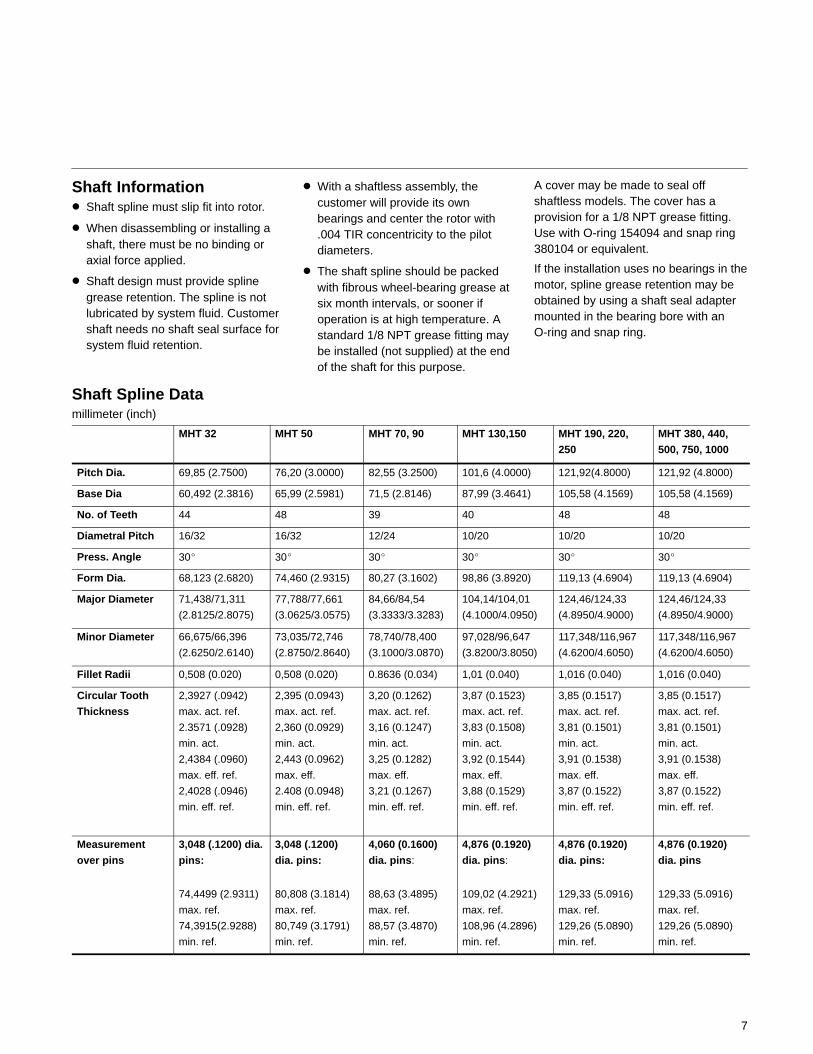
Shaft Information� Shaft spline must slip fit into rotor.
� When disassembling or installing a shaft, there must be no binding or axial force applied.
� Shaft design must provide spline grease retention. The spline is not lubricated by system fluid. Customer shaft needs no shaft seal surface for system fluid retention.
� With a shaftless assembly, the customer will provide its own bearings and center the rotor with .004 TIR concentricity to the pilot diameters.
� The shaft spline should be packed with fibrous wheel-bearing grease at six month intervals, or sooner if operation is at high temperature. A standard 1/8 NPT grease fitting may be installed (not supplied) at the end of the shaft for this purpose.
A cover may be made to seal offshaftless models. The cover has aprovision for a 1/8 NPT grease fitting.Use with O-ring 154094 and snap ring380104 or equivalent.
If the installation uses no bearings in themotor, spline grease retention may beobtained by using a shaft seal adaptermounted in the bearing bore with anO-ring and snap ring.
Shaft Spline Datamillimeter (inch)
MHT 32 MHT 50 MHT 70, 90 MHT 130,150 MHT 190, 220,
250
MHT 380, 440,
500, 750, 1000
Pitch Dia. 69,85 (2.7500) 76,20 (3.0000) 82,55 (3.2500) 101,6 (4.0000) 121,92(4.8000) 121,92 (4.8000)
Base Dia 60,492 (2.3816) 65,99 (2.5981) 71,5 (2.8146) 87,99 (3.4641) 105,58 (4.1569) 105,58 (4.1569)
No. of Teeth 44 48 39 40 48 48
Diametral Pitch 16/32 16/32 12/24 10/20 10/20 10/20
Press. Angle 30� 30� 30� 30� 30� 30�
Form Dia. 68,123 (2.6820) 74,460 (2.9315) 80,27 (3.1602) 98,86 (3.8920) 119,13 (4.6904) 119,13 (4.6904)
Major Diameter 71,438/71,311
(2.8125/2.8075)
77,788/77,661
(3.0625/3.0575)
84,66/84,54
(3.3333/3.3283)
104,14/104,01
(4.1000/4.0950)
124,46/124,33
(4.8950/4.9000)
124,46/124,33
(4.8950/4.9000)
Minor Diameter 66,675/66,396
(2.6250/2.6140)
73,035/72,746
(2.8750/2.8640)
78,740/78,400
(3.1000/3.0870)
97,028/96,647
(3.8200/3.8050)
117,348/116,967
(4.6200/4.6050)
117,348/116,967
(4.6200/4.6050)
Fillet Radii 0,508 (0.020) 0,508 (0.020) 0.8636 (0.034) 1,01 (0.040) 1,016 (0.040) 1,016 (0.040)
Circular Tooth
Thickness
2,3927 (.0942)
max. act. ref.
2.3571 (.0928)
min. act.
2,4384 (.0960)
max. eff. ref.
2,4028 (.0946)
min. eff. ref.
2,395 (0.0943)
max. act. ref.
2,360 (0.0929)
min. act.
2,443 (0.0962)
max. eff.
2.408 (0.0948)
min. eff. ref.
3,20 (0.1262)
max. act. ref.
3,16 (0.1247)
min. act.
3,25 (0.1282)
max. eff.
3,21 (0.1267)
min. eff. ref.
3,87 (0.1523)
max. act. ref.
3,83 (0.1508)
min. act.
3,92 (0.1544)
max. eff.
3,88 (0.1529)
min. eff. ref.
3,85 (0.1517)
max. act. ref.
3,81 (0.1501)
min. act.
3,91 (0.1538)
max. eff.
3,87 (0.1522)
min. eff. ref.
3,85 (0.1517)
max. act. ref.
3,81 (0.1501)
min. act.
3,91 (0.1538)
max. eff.
3,87 (0.1522)
min. eff. ref.
Measurement
over pins
3,048 (.1200) dia.
pins:
74,4499 (2.9311)
max. ref.
74,3915(2.9288)
min. ref.
3,048 (.1200)
dia. pins:
80,808 (3.1814)
max. ref.
80,749 (3.1791)
min. ref.
4,060 (0.1600)
dia. pins:
88,63 (3.4895)
max. ref.
88,57 (3.4870)
min. ref.
4,876 (0.1920)
dia. pins:
109,02 (4.2921)
max. ref.
108,96 (4.2896)
min. ref.
4,876 (0.1920)
dia. pins:
129,33 (5.0916)
max. ref.
129,26 (5.0890)
min. ref.
4,876 (0.1920)
dia. pins
129,33 (5.0916)
max. ref.
129,26 (5.0890)
min. ref.

8
Application Data
Start-Up Procedure
CAUTION: Failure to follow properstart-up procedures may damage themotor and system. Avoid dry shocksand thermal starts to prevent damageto the system or motor.
When an MHT motor is initially started,caution should be taken to ensurecomplete internal lubrication.Thefollowing will help ensure proper internallubrication at start-up.
� Fill the unit with oil.
� Start split rise motors in fulldisplacement.
� Set the speed control at 10 rpm or less.
� Jog the motor.
� Check for and maintain case drainflow while operating motor.
� Increase speed in low increments withload 35–69 bar (500–1000 psi)preferred.
� Warm the hydraulic system and themotor simultaneously.
Functional SymbolsStandard Motor
Multi-torque motorsMotor Installation possibilities for full and partial displacement and bothdirections of rotation
Full Displacement
One Rotation
Partial Displacement
Opposite Rotation
Full Displacement Partial Displacement
CAUTION: AVOID CIRCUITS WHERE ANY CONDITIONS COULD CAUSEINTENSIFIED PRESSURE. MULTI-DISPLACEMENT MOTORS CANEXPERIENCED INTENSIFIED PRESSURES UNDER SOME CIRCUITCONDITIONS SUCH THAT PRESSURES WILL EXCEED THE MOTOR,PIPING, OR VALVE RATING. SEE EXAMPLE BELOW.
Port B
Port A2
Port A1Blocked
No Load
Intensified pressure inexcess of “B” pressure

9
Bearing CapacityModel Bearing Capacity
N (lbf) AFBMA 33 1/3 rpm500 hours, B–10 life
Bearing CapacityN (lbf) @ 50 rpm15000 hours average life
MHT 32 22552 (5070) 10787 (2425)
MHT 50 23486 (5280) 11231 (2525)
MHT 7029180 (6560)
13967 (3140)
MHT 9029180 (6560)
17526 (3940)
MHT 13036631 (8235)
MHT 15036631 (8235)
MHT 190
MHT 220
MHT 25026689 (6000)
MHT 38055691 (12520)
26689 (6000)
MHT 44055691 (12520)
MHT 500
MHT 750
MHT 1000
Inertia of Rotating Group (approximate)Model Without Shaft With Shaft
Nm2 (lb.-in2) Nm-sec2 (lb.-in-sec2) Nm2 (lb.-in2) kg-cm2-sec2 (lb.-in-sec2)
MHT 32 5,7 (50) 1.47 (13) 6,8 (60) 1,81 (16)
MHT 50 16,4 (145) 4.29 (38) 18,3 (162) 4,75 (42)
MHT 7029 6 (262) 7 68 (68) 32 3 (286) 8 36 (74)
MHT 9029,6 (262) 7.68 (68) 32,3 (286) 8,36 (74)
RotationMHT–32Fluid to Port B gives clockwise rotationviewed from port A end, and fluid toport a gives counter-clockwiserotation.
All othersFluid to Port A gives clockwiserotation, and fluid to port B givescounter-clockwise rotation.

10
MHT 13053 9 (477) 0 14 (1 24) 32 3 (548) 0 16 (1 42)
MHT 15053,9 (477) 0,14 (1.24) 32,3 (548) 0,16 (1.42)
MHT 190
MHT 220 106,2 (940) 0,28 (2.43) 124,3 (1100) 0,32 (2.85)
MHT 250
MHT 380
MHT 440 212,4 (1880) 0,55 (4.86) 239,2 (2117) 0,62 (5.47)
MHT 500
MHT 750 318,6 (2820) 0,82 (7.29) 352,2 (3117) 0,91 (8.06)
MHT 1000 424,8 (3760) 1,10 (9.72) 464,9 (4115) 1,2 (10.65)

11
Performance DataTypical performance in 10W oil at 49�C (120�F) and 137 bar (2000 psi)
MHT32
MHT50
25 50 75 100 125 150 175 200 225 250 275 300 325 350 375 4000
38 (10)
76 (20)
114 (30)
151 (40)
189 (50)
227 (60)
00
135 (100)
271 (200)
406 (300)
542 (400)
678 (500)
813 (600)
Output Torque
Inlet Flow
0
38 (10)
76 (20)
114 (30)
151 (40)
189 (50)
227 (60)
Speed (rpm)
Speed (rpm)
265 (70)
0
271 (200)
542 (400)
813 (600)
1085 (800)
1356 (1000)
1627 (1200)
1898 (1400)207 bar (3000 psi)
Torque
138 bar (2000 psi)
Flow In
Case Flow
138 bar (2000 psi)
69 bar (1000 psi)
100 200 300 375
Inle
t F
low
(l/m
in (
US
gp
m)
Torq
ue
Nm
(F
t, L
bs.
)
Inle
t F
low
(l/m
in (
US
gp
m)
Torq
ue
Nm
(F
t, L
bs.
)

12
Typical performance in 10W oil at 49�C (120�F) and 137 bar (2000 psi)
MHT70 &MHT90
0
38 (10)
76 (20)
116 (30)
151 (40)
189 (50)
227 (60)
265 (70)
303 (80)
341 (90)
379 (100)
100 200 300
271 (200)
542 (400)
814 (600)
1085 (800)
1356 (1000)
1627 (1200)
1898 (1400)
2169 (1600)
2441 (1800)
2712 (2000)
MHT 90 output torque
MHT 70 output torque
MHT 90 MHT 70
Case Flow
0
8 (2)
Speed (rpm)
Torq
ue
Nm
(lb
. ft.
)
MHT130& MHT150
76 (20)
151 (40)
227 (60)
303 (80)
379 (100)
20 60 100 140 180 240 260
Inle
t F
low
lpm
(U
Sg
pm
)
TORQUE
INPUT FLOW
CASE FLOW678 (500)
1356 (1000)
2034 (1500)
2711 (2000)
3390 (2500)
4067 (3000)
Speed (rpm)
Torq
ue
Nm
(lb
. ft.
)
379 (120)
Inle
t F
low
lpm
(U
Sg
pm
)
220
13
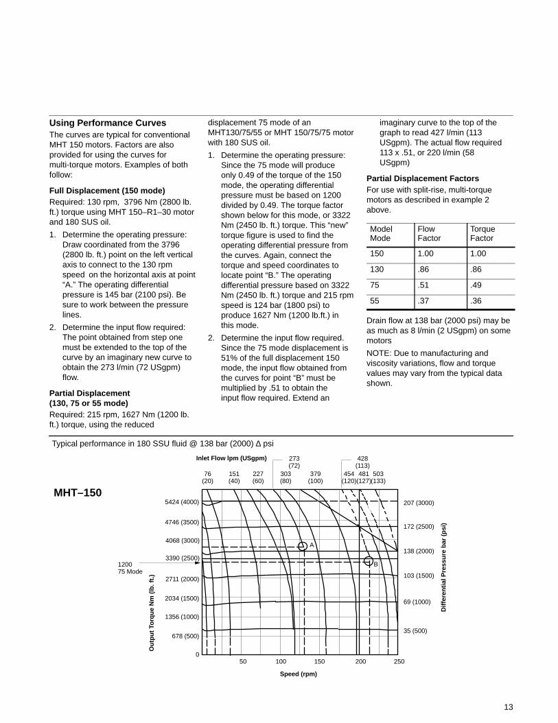
Using Performance CurvesThe curves are typical for conventionalMHT 150 motors. Factors are alsoprovided for using the curves formulti-torque motors. Examples of bothfollow:
Full Displacement (150 mode)Required: 130 rpm, 3796 Nm (2800 lb.ft.) torque using MHT 150–R1–30 motorand 180 SUS oil.
1. Determine the operating pressure:Draw coordinated from the 3796(2800 lb. ft.) point on the left vertical axis to connect to the 130 rpm speed on the horizontal axis at point“A.” The operating differential pressure is 145 bar (2100 psi). Be sure to work between the pressure lines.
2. Determine the input flow required:The point obtained from step one must be extended to the top of the curve by an imaginary new curve to obtain the 273 l/min (72 USgpm) flow.
Partial Displacement (130, 75 or 55 mode)Required: 215 rpm, 1627 Nm (1200 lb.ft.) torque, using the reduced
displacement 75 mode of anMHT130/75/55 or MHT 150/75/75 motorwith 180 SUS oil.
1. Determine the operating pressure:Since the 75 mode will produce only 0.49 of the torque of the 150mode, the operating differential pressure must be based on 1200divided by 0.49. The torque factor shown below for this mode, or 3322Nm (2450 lb. ft.) torque. This “new” torque figure is used to find the operating differential pressure from the curves. Again, connect the torque and speed coordinates to locate point “B.” The operating differential pressure based on 3322 Nm (2450 lb. ft.) torque and 215 rpmspeed is 124 bar (1800 psi) to produce 1627 Nm (1200 lb.ft.) inthis mode.
2. Determine the input flow required. Since the 75 mode displacement is 51% of the full displacement 150 mode, the input flow obtained from the curves for point “B” must be multiplied by .51 to obtain the input flow required. Extend an
imaginary curve to the top of the graph to read 427 l/min (113 USgpm). The actual flow required 113 x .51, or 220 l/min (58USgpm)
Partial Displacement FactorsFor use with split-rise, multi-torquemotors as described in example 2above.
ModelMode
FlowFactor
TorqueFactor
150 1.00 1.00
130 .86 .86
75 .51 .49
55 .37 .36
Drain flow at 138 bar (2000 psi) may beas much as 8 l/min (2 USgpm) on somemotors
NOTE: Due to manufacturing andviscosity variations, flow and torquevalues may vary from the typical datashown.
Typical performance in 180 SSU fluid @ 138 bar (2000) ∆ psi
0
1356 (1000)
2034 (1500)
2711 (2000)
4746 (3500)
5424 (4000)
50 100 150 200
35 (500)
69 (1000)
103 (1500)
138 (2000)
Inlet Flow lpm (USgpm)
76(20)
151(40)
227(60)
303(80)
379(100)
454(120)
481(127)
503(133)
Dif
fere
nti
al P
ress
ure
bar
(p
si)
Ou
tpu
t To
rqu
e N
m (
lb. f
t.)
Speed (rpm)
MHT–150
120075 Mode
273(72)
678 (500)
250
172 (2500)
3390 (2500)
4068 (3000)
428(113)
A
B
207 (3000)
14
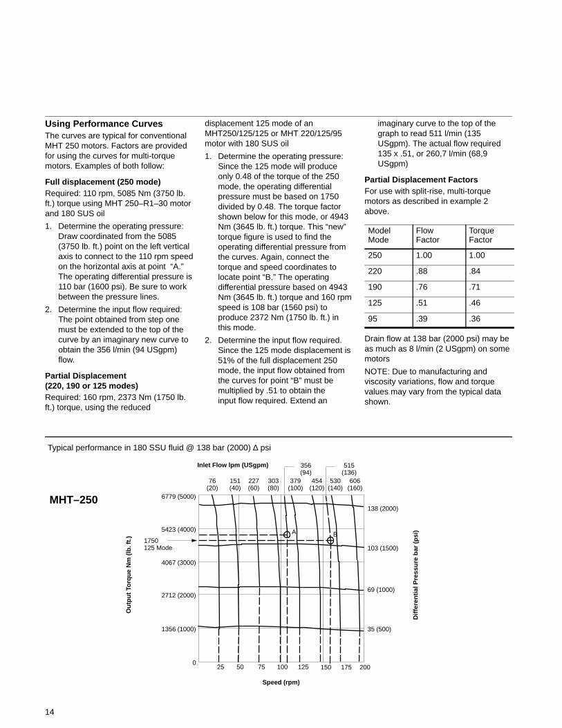
Using Performance CurvesThe curves are typical for conventionalMHT 250 motors. Factors are providedfor using the curves for multi-torquemotors. Examples of both follow:
Full displacement (250 mode)Required: 110 rpm, 5085 Nm (3750 lb.ft.) torque using MHT 250–R1–30 motorand 180 SUS oil
1. Determine the operating pressure:Draw coordinated from the 5085(3750 lb. ft.) point on the left vertical axis to connect to the 110 rpm speedon the horizontal axis at point “A.” The operating differential pressure is110 bar (1600 psi). Be sure to work between the pressure lines.
2. Determine the input flow required:The point obtained from step one must be extended to the top of the curve by an imaginary new curve to obtain the 356 l/min (94 USgpm) flow.
Partial Displacement(220, 190 or 125 modes)Required: 160 rpm, 2373 Nm (1750 lb.ft.) torque, using the reduced
displacement 125 mode of anMHT250/125/125 or MHT 220/125/95motor with 180 SUS oil
1. Determine the operating pressure:Since the 125 mode will produce only 0.48 of the torque of the 250mode, the operating differential pressure must be based on 1750 divided by 0.48. The torque factor shown below for this mode, or 4943Nm (3645 lb. ft.) torque. This “new” torque figure is used to find the operating differential pressure from the curves. Again, connect the torque and speed coordinates to locate point “B.” The operating differential pressure based on 4943 Nm (3645 lb. ft.) torque and 160 rpmspeed is 108 bar (1560 psi) to produce 2372 Nm (1750 lb. ft.) in this mode.
2. Determine the input flow required. Since the 125 mode displacement is 51% of the full displacement 250 mode, the input flow obtained from the curves for point “B” must be multiplied by .51 to obtain the input flow required. Extend an
imaginary curve to the top of the graph to read 511 l/min (135 USgpm). The actual flow required 135 x .51, or 260,7 l/min (68,9 USgpm)
Partial Displacement FactorsFor use with split-rise, multi-torquemotors as described in example 2above.
ModelMode
FlowFactor
TorqueFactor
250 1.00 1.00
220 .88 .84
190 .76 .71
125 .51 .46
95 .39 .36
Drain flow at 138 bar (2000 psi) may beas much as 8 l/min (2 USgpm) on somemotors
NOTE: Due to manufacturing andviscosity variations, flow and torquevalues may vary from the typical datashown.
Typical performance in 180 SSU fluid @ 138 bar (2000) ∆ psi
0
1356 (1000)
2712 (2000)
4067 (3000)
5423 (4000)
6779 (5000)
25 50 75 100 125 150 175 200
35 (500)
69 (1000)
103 (1500)
138 (2000)
Inlet Flow lpm (USgpm)
76(20)
151(40)
227(60)
303(80)
379(100)
454(120)
530(140)
606(160)
Dif
fere
nti
al P
ress
ure
bar
(p
si)
Ou
tpu
t To
rqu
e N
m (
lb. f
t.)
Speed (rpm)
MHT–250
1750125 Mode
BA
356(94)
515(136)

15
Using Performance CurvesThe curves are typical for conventionalMHT 500 motors. Factors are providedfor using the curves for multi-torquemotors. Examples of both follow:
Full displacement (500 mode)Required: 90 rpm, 9830 Nm (7250 lb. ft.)torque using MHT 500–R1–30 motorand 180 SUS oil
1. Determine the operating pressure:Draw coordinated from the 9830 (7250 lb. ft.) point on the left vertical axis to connect to the 90 rpm speed on the horizontal axis at point “A.” The operating differential pressure is108 bar (1565 psi). Be sure to work between the pressure lines.
2. Determine the input flow required:The point obtained from step one must be extended to the top of the curve by an imaginary new curve to obtain the 582 l/min (154 USgpm) flow.
Partial Displacement (250 or 190 modes)Required: 150 rpm, 3000 lb. ft. torque,using the reduced displacement 250
mode of an MHT 500/250/250 motorwith 180 SUS oil
1. Determine the operating pressure:Since the 250 mode will produce only 0.48 of the torque of the 500 mode, the operating differential pressure must be based on 3000 divided by 0.48. The torque factor shown below for this mode, or 8475 Nm (6250 lb. ft.) torque. This “new” torque figure is used to find the operating differential pressure from the curves. Again, connect the torque and speed coordinates to locate point “B.” The operating differential pressure based on 8475 Nm (6250 lb. ft.) torque and 150 rpmspeed is 97 bar (1400 psi) to produce 4068 Nm (3000 Lb. Ft.) in this mode.
2. Determine the input flow required:Since the 250 mode displacement is 48% of the full displacement 500 mode, the input flow obtained from the curves for point “B” must be multiplied by .48 to obtain the gpm input flow required. Extend an
imaginary curve to the top of the graph to read 973 l/min (257 USgpm). The actual flow required is 257 x .48, or 469 l/min (124 USgpm).
Partial Displacement FactorsFor use with split-rise, multi-torquemotors as described in example 2above.
ModelModel
FlowFactor
TorqueFactor
440 .88 .84
380 .76 .71
250 .48 .46
190 .36 .36
Drain flow at 138 bar (2000 psi) may beas much as 8 l/min (2 USgpm) on somemotors
NOTE: Due to manufacturing andviscosity variations, flow and torquevalues may vary from the typical datashown.
1356 (1000)
2711 (2000)
4067 (3000)
5423 (4000)
6779 (5000)
8135 (6000)
9491 (7000)9830 (7250)
10847 (8000)
12202 (9000)
13558 (10000)
20 40 60 80 100 120 140 160 180 200
35 (500)
69 (1000)
103 (1500)
138 (2000)
Dif
fere
nti
al P
ress
ure
bar
(p
si)
Ou
tpu
t to
rqu
e N
m (
Ft.
Lb
s.)
Speed (rpm)
76(20)
227(60)
379(100)
530(140)
681(180)
833(220)
984(260)
1136(300)
Inlet Flow l/min (Usgpm)
583(154)
973(257)
MHT500
Typical performance in 180 SSU fluid @ 138 bar (2000) ∆ psi
3000250 mode
A 108 bar (1565 psi)
B 97 bar (1400 psi)

16
Typical performance in 180 SSU fluidInlet pressure 103 �bar (1500 �psi)Inlet temperature 49 �C (120�F)
MHT–1000
MHT750
Tota
l Flo
w l/
min
(U
Sg
pm
)%
Eff
icie
ncy
0
4 (1.0)
8 (2.0)
11 (3.0)
15,0 (4.0)
Cas
e F
low
l/m
in (
US
gp
m)
Total Flow
Case Flow
151 (40)
31 (80)
454 (120)
606 (160)
757 (200)
909 (240)
1060 (280)
60
70
80
90
100
Torque EfficiencyVolumetric Efficiency
Overall Efficiency
2711 (2000)
5423 (4000)
8135 (6000)
10847 (8000)13558 (10000)
Torq
ue
Nm
(L
b. F
t.)
20 30 40 50 60 70 80 90 100110
Speed (rpm)
Torque
10 20 30 40 50 60 70 75
151 (40)
303 (80)
454 (120)
606 (160)
757 (200)
908 (240)
1060 (280)
40
5060
708090
100
10847 (8000)12202 (9000)13558 (10000)
Speed (rpm)
Tota
l Flo
w l/
min
(U
Sg
pm
)%
Eff
icie
ncy
0
120
Torq
ue
Nm
(L
b. F
t.)
17
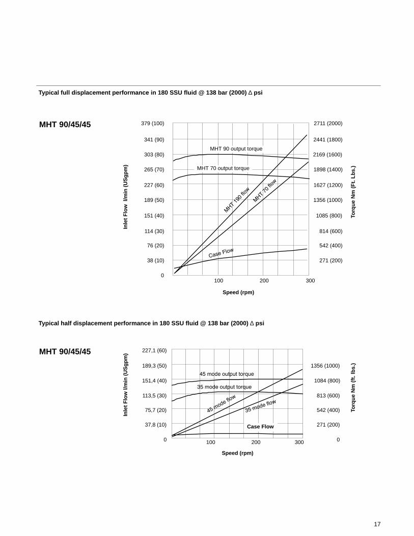
Typical full displacement performance in 180 SSU fluid @ 138 bar (2000) ∆ psi
0
38 (10)
76 (20)
114 (30)
151 (40)
189 (50)
227 (60)
265 (70)
303 (80)
341 (90)
379 (100)In
let
Flo
w l
/min
(U
Sg
pm
)
Speed (rpm)
100 200 300
271 (200)
542 (400)
814 (600)
1085 (800)
1356 (1000)
1627 (1200)
1898 (1400)
2169 (1600)
2441 (1800)
2711 (2000)
Torq
ue
Nm
(F
t. L
bs.
)
MHT 90 output torque
MHT 70 output torque
MHT 90/45/45
Typical half displacement performance in 180 SSU fluid @ 138 bar (2000) ∆ psi
0
37,8 (10)
75,7 (20)
113,5 (30)
151,4 (40)
189,3 (50)
227,1 (60)
100 200 300 0
271 (200)
542 (400)
813 (600)
1084 (800)
1356 (1000)
Inle
t F
low
l/m
in (
US
gp
m)
Torq
ue
Nm
(ft
. lb
s.)
Speed (rpm)
Case Flow
MHT 90/45/45
18
Typical half displacement performance in 180 SSU fluid @ 138 bar (2000) ∆ psi
20 40 60 80 100 120 140 160
77 (20)151 (40)227 (60)303 (80)
379 (100)454 (120)530 (140)606 (160)681 (180)757 (200)833 (220)909 (240)
405060708090
100
Cas
e F
low
– l/
min
(U
Sg
pm
)To
rqu
e N
m (
lb. f
t.)
Speed (rpm)
4 (1)8 (2)11 (3)15 (4)
Tota
l Flo
w –
l/m
in (
US
gp
m)
% E
ffic
ien
cy
175
86 (64)90 (66)92 (68)
Torque EfficiencyVolumetric Efficiency
Overall Efficiency
Total Flow
Case Flow
MHT 380/190/190
MHT 440/250/190
20 40 60 80 100 120 140 150
77 (20)
151 (40)227 (60)
303 (80)379 (100)
454 (120)
50
6070
8090
100
% E
ffic
ien
cy
103 (76)
106 (76)
108 (80)
111 (82)
Speed (rpm)
Tota
l Flo
w –
l/m
in (
US
gp
m)
Cas
e F
low
l/m
in (
US
gp
m)
Cas
e F
low
l/m
in (
US
gp
m)
0
4 (1)
8 (2)
11 (3)
19
Typical half displacement performance in 180 SSU fluid @ 138 bar (2000) ∆ psi
TORQUE
250 MODE
190 MODE
TORQUE
INPUT FLOW
CASE FLOW
0
95 (25)
189 (50)
284 (75)
379 (100)
473 (125)
568 (150)
662 (175)
4 (1.0)
8 (2.0)
11 (3.0)
3390 (2500)
4068 (3000)
4745 (3500)
5423 (4000)
6101 (4500)
Inle
t F
low
– G
PM
Torq
ue
– N
m (
lb. F
t.)
MHT 500/250/250
Cas
e F
low
100
Speed (rpm)
200

20
MHT 32
.4375–20–UNF–2B straight thd.Case drain connections.Do not restrict case flow. Onlyone case drain required.Others plugged
76,2(3.00) dia.clearancethru bothbodies
95,00/95,02(3.7401/3.7409)Dia. counterbore,both bodies
113,82/113,56(4.481/4.471)
24,33(0.958)
Ref
53,9(2.12)
54,4(2.1)Typ.
12,7(0.50)
40,41/40,16 (1.591/1.581)
33,02(1.300)
113,67/113,54 (4.475/4.470)
1/8” NPT pipe tap forgrease fitting
59,99/60,002.3616/2.3622ID Bearing diameter
95,0/94,98(3.7402/3.7396) O.D.Bearing Diameter
250,7(9.87)
162,56(6.40)
88,9(3.47)Nom.
87,63(3.45)
37,33(1.47)
57,099 (2.247)
58,7 (2.312)
29,46(1.16)
Alternate thru mounting bolts – 6 places.500–13 UNC–2A thd.
0.4375–1A–UNC–2B4 holes, 2 placesfor std 4-bolt flange for1.25 O.D. dia. tubing
Port B connection SAE 1.25 dia. nominal
30,17(1.188)
14,99(0.59)
64,26 (2.53) Both bodies
.500–13 UNC–2B mounting holes (ref) 6 places equally spaced, located as shown ,on 203mm (8.00 in.) dia. B.C.
CAUTION: DEPTH OF MOUNTING SCREWSNOT TO EXCEED 31,75 (1.25) IN BODY.
15° 15°
62,9/62,6(2.477/2.467)
239,78/237,49(9.44/9.35)cast dia.
12,72/12,70(.501/.500) sq. keyx 57,15 (2.25) long
.500–13 UNC–2A6 screws – 4.50 longequally spaced on 203,2 (8.00) dia. b.c.
155,5 (6.12) dia.x 0,38 (0.015)deep both faces
254,0(10.0)
133,35(5.25)
162,56 (6.40) Ref
18,00(.7087)Bearing
26,29(1.035)
typ.
71,83(2.828)
98,14(3.864)
26,29(1.035)
typ
71,83(2.828)
82,52/82,58(3.249/3.251)
Dia.
Installation DimensionsMillimeters (inches)
SAE 1.25 nom. dia.Port A connection
Pilot dia. use94,95–94,89(3.738–3.736) dia. male pilot, 2,5 (0.100) max. pilot depth

21
MHT 50
54,10 (2.13)
149,86(5.90) 28,96/26,92 (1.14/1.06)
12,7/16,51 (.50/.65)
82,55 (3.25) dia. shaft clearance
99,9998/100,02(3.9370/3.9380)cbore & pilot dia.
40,9 (1.61)
70,86/68,83 (2.79/2.71)
136,9/134,87 (5.39/5.31)
.5625–18 UNF–2BSAE internal straight thd.connection2 places
295,14 (11.62)
88,9(3.5)
149,15(5.872)
99,99/100,02(3.9370/3.9380O.D. Bearing
40,89 (1.61)
0.125–27 NPT for grease fitting
15° 15°
304,3/299,21(11.98/11.78)
158,756.25(bothsides)
288,54/283,9(11.36/11.18)
diameter castingdimensions
187,45(7.38)diameter reliefboth bodies
250,83(9.875)
b.c. relief
88,9(3.50)
121,13(4.769)
typ.
88,67(3.491)
typ.
32,46(1.278)
typ.
121,13(4.769)
typ.
88,67(3.491)
typ32,46(1.278)
typ.
0.625–11 UNC-2Bmounting holes
CAUTION: DEPTH OFMOUNTING SCREWSSHALL NOT EXCEED44,4 (1.75) INTO BODY
307,34/299,72(12.1/11.8)
207,26/204,22(8.16/8.04)
123,19(4.85)
28,45(1.12)
63,5 (2.5) lg. key
58,72(2.312)
29,46(1.16)
.4375–14 UNC–2B4 flange mounting holes2 places, 1.13 deep
30,18(1.188)
14,9 (0.59)
Port A forstandardSAE 1.25diameter4 bolt flange
Port B forstandardSAE 1.25diameter4 bolt flange
65,00/64,99(2.5591/2.5585)I.D. Bearing 63,45/63,42
(2.498/2.497)70,56/70,3 (2.778/2.768)
15,88/15,9 (.625/.626)
Alternate thrumounting stud
18,00/17,87 (.7087/.7037) Bearing Width
B
A
0.79 (0.031) deep x261,6 (10.30) dia.Body undercut
8.64/6,1 (0.34/0.24)max. penetrationof mating pilot 5,84 (0.230)
20,57(0.810)
2,79(0.110)
0,762(0.030)R
Detail A
see Detail A
Installation DimensionsMillimeters (inches)

22
MHT 70 and 90
69,85 (2.750) typ.
35,05 (1.38) typ.
Port connection BStandard 4-bolt 1.50dia. SAE flange
.5000–13–UNC–2B 4 flange mounting holes – 2 places
CAUTION: DEPTH OFSCREWS NOT TO EXCEED19,05 mm (0.75 in.)
Port connection AStd. 4-bolt 1.50 dia.SAE flange
28,45(1.12)100,33/95.25 (3.95/3.75)
327,66/319,53(12.90/12.58)
Alternate thru mounting studsTorque to 169 � 7 Nm (125 � 5 lb.ft.).625–11 UNC–2A Thd.
302,5–308.10(11.91–12.13 Diacasting dimensions
266,7(10.50) dia B.C. ref.
205,74(8.10) dia. casting relief
308,61/313,69(12.15/12.35)
0.625–11 UNC–2A thd6 screws, 6.00 longequally spaced, locatedas shown
0.625–11 UNC–2A thd6 screws, 6.00 longequally spaced, locatedas shown.Torque mountingscrews to 81–95 Nm(60–70 lb. ft.) oiled.
CAUTION: DEPTH OFMOUNTING SCREWSSHALL NOT EXCEED44,4 (1.75) INTO BODY
128,8(5.071)
94,28(3.712)
34,52 (1.359)
70,56/70,30(2.778/2.768)
158,75 (6.25)
34,52(1.359)
128.8 (5.071)
94,28(3.712)
15° 15°
73,66(2.90)
165,61 (6.52)
73,66 (2.90)
.5625–18 UNF–2B straight thd.drain connections.Connect so that drain line is unrestricted.Only one case drain required. Others maybe plugged
164,72(6.485)
69.984/69,999(2.7553/2.7559)
I.D. Bearing
56,13(2.21)
0.125–27 NPTfor grease fitting
52,32(2.06)
317,5(12,5)
109,99/109,98(4.3309/4.3301)
Bearing O.D.
19,99/19,87(.7874/.7824)bearing width
Shaft spline(see “ShaftSpline Data” inthis catalog.
15,78 (.62) Radius
29,21/31,24 (1.15/1.23)
109,99/110,04(4.3307/4.3322)counterbore andpilot diameterboth bodies
44,45 (1.75)136,9(5.39)44,45
(1.75)
12,70/16,51 (.50/.65)88,9(3.50)dia.shaft clearanceboth bodies
109,99/109,98(4.3309/4.3301)
see detail “A”
22,73(.895)
2,79(.110)
5,84(.230) 5,84
(0.23)
Detail “A”
43,4/45,5(1.71/1.79)typ.
88,9 (3.50) min. straight
35,7(1.406)
17,78 (0.70)
136,9 (5.39)
63,5(2.5)
63,45/63,42 (2.498/2.497)
70,56/70,30 (2.778/2.768)
86,3 (3.40)
8.95/8.83(227,33/224,28)
15,88 (0.625) sq x 63,5 (2.50) long
95,25 (3.75 Both Bodies
Installation DimensionsMillimeters (inches)

23
MHT 130 and MHT 150
105,51(4.154) 144,14
(5.765)
38,63 (1.521)
144,15 (5.675)
105,51 (4.154)
38,63 (1.521)
187,5(7.38)
346,71/352,30(13.65/13.87)
298,5(11,75)b.c. ref
345,18/340,61(13,59/13,41)
dia. casting dim.
120,65(4.75)
225,45/225,52(8.876/8.879)pilot dia.
25,4(1.00)
1.687 (42.85)
77.78 (3.062) typ.
360,7/366,7(14.20/14.44)
252.5/255,5(9.94/10.06)
154,31/155,32(6.075/6.115)
112/106,9 (4.41/4.21)
50,5/48,5 (1.99/1.91)
15� 15�
81,53/83,56 (3.21/3.29) typ
170,43/172,46 (6.71/6.79)
104,65(4.12) dia shaft clearanceboth bodies
194,31/195,32 (7.650/7.690)18,29(0.79)
.5625–18UNF–2B SAEstraight thd.Drain connection2 places
125,001/125,039(4.9213/4.9228)c bore & pilotdia. both bodiesRotor spline
355,6(14.00)
194,056(7.640)
66,04(2.60)
61,97(2.44)
125,001/124,976(4.9213/4.9203)bearing O.D.
79,985/80,000(3.1490/3.1496)bearing I.D. 22,00/21,87 (.8661/.8611) bearing width
.500–13 UNC -2B25.4 (1.00) deep8 flange mtg. holes.
19,05/19,08 (.750/.751)
84,63/84,38 (3.332/3.322)
76,15/76,12 (2.998/2.997)
SAE 2.00 dia. 4-bolt flange.
125,00/124,98 (4.9214/4.9204)84,07 (3.31)
.625–11 UNC-2A stdassembly screws165 (6.5) long.6 places equallyspaced.
.625–11 UNC-2Bmtg holes. 6 placesequally spaced.38,1 (1.50) maxdepth. Torque to81–95 Nm(60–70 lb. ft.) oiled
Both Bodies
101,35(3.990)
38,9 (1.53) typ.
24,89(0.980)
2,79 (0.110)
7,62 (0.30)Detail “A”
5,97/3,43(0.235/0.135)
3,05(0.120)
10,00/9,80(0.394/0.386)
20�
0,76 (0.030)
see Detail A
Installation DimensionsMillimeters (inches)
Port A
Port B
24
MHT 190, MHT 220, MHT 250
15� 15�
B
A
98,73/94,48 (3.887/3.877)
88,85/88,90 (3.498/3.500)
88,9(3.500)
44,45(1.75)
22,23/22,25(0.876/0.875)
50,8 (2.00) typ
25,4 (1.00) typ
.500 UNC–2B 1.25 deep 4-flangemounting holes 2 places for std. SAE63,5 (2.50) depth
56,64/54,61 (2.23/2.15)
56,64/54,61(2.23/2.15)
182,63(7.19)
398,01/392,94(15.67/15.47)casting dim
342,9(13.5)b.c. relief
263,58/263,47(10.377/10.373)dia. typical
401,57406,91(15.81/16.02)
165,58(6.519)
449,83/446,28(17.71/17.57)
295,40/291,85(11.63/11.49)
156,21/152,40 (6.15/6.00)
165,58(6.519)
121.21(4.772)
44,37(1.747)
107,95 (4.25)
206,25(8.12)
Both Bodies
44,37(1.747)
117,35(4.62)
225,3(8.87)
127,0(5.0)dia. shaft clearanceboth bodies
.8750–14 UNF 2B SAE internal straight thd.(drain connection)2 places
221,82/220,80 (8.733/8.693)
37,08/35,05 (1.46/1.38)
21,45 (1.12)
160,034/159,999(6.3007/6.2992)cbore & pilot diametersboth bodies
203,45/201,42 (8.01/7.93)
92,20/90,17 (3.63/3.55)
220,80/220,29(8.693/8.673)
77,72 (3.06)
71,37 (2.81)
440,69/437,13(17.35/17.21)
104,98105,001(4.1331/4.1339)
bearing I.D.
159,99/159,97(6.2992/6.2982)
25,99/25,87 (1.0236/1.0186)
71,37 (2.81)
28,83(1.135)
2,79(0.110)
7,62(0.30)
Detail “A”
8.63/6,10(0.34/0.24)
3,05(0.120)
10,00/9,80(0.394/0.386)
20�
0,76(0.030)
see Detail A
Installation DimensionsMillimeters (inches)
25
MHT 380, MHT 440, MHT 500
15� 15�
112,80/112,55 (4.441/4.431)
101,55/101,52 (3.998/3.997)
398,01/392,94(15.67/15.47)casting dim
342,9(13.5)b.c. relief
401,57406,91(15.81/16.02)
typ
165,58(6.519)typ
165,5 (6.519) typ
121.2 (4.772) typ
44,37 (1.747) typ
206,25(8.12)
typ
Both Bodies
44,37(1.747)
typ
117,35(4.62)
284,73//286,26(11.21/11.27)
399,29/394,46(15.72/15.53)
559,56/560,58(22.23/22.07)
56,64/54,61 (2.23/2.15)
103,12 (4.06)
146,81 (5.78)
127,0 (5.0) key length
50,8 (2.0)
25,4 (1.0)
44,45 (1.75)
88,9 (3.50)
Ports A and B forstandard SAE2.50 dia4-bolt flange
0.500–13 UNC–2B1.25 deep, 4-flangemounting holes, 2places.
B
A
263,58/263,47(10.377/10.373)dia. typical
25,43/25.40 (1.001/1.000)
77,72 (3.06) 71,37 (2.81)
556,51/552,96 (21.91/21.77)
104,98105,001(4.1331/4.1339)
bearing I.D.
159,99/159,97(6.2992/6.2982)
25,99/25,87 (1.0236/1.0186) Bearing Width
215,64/213,11 (8.49/8.39)
.8750–14–UNF–2BSAE Internal straight thread2 places (drain connection)
12,7(0.5)dia shaftclearanceboth bodies
325,37/323,60(12.81/12.74)37,08/35,05
(1.46/1.38)
19,05 (0.75) typ
92,2/90,17(3.63/3.55)
159,99/159,97(6.2992/6.2982)c’bore & pilot dia.
grease fitting
323,7/323,22(12.745/12.725)
180,85(7.12)
25,4(1.00)
28,8(1.135)
7.87(0.31)
Detail “A”
2,79(0.110)
8,63/6,10(0.34/0.24)
see Detail A
Installation DimensionsMillimeters (inches)

26
MHT 750
15� 15�
112,80/112,55(4.441/4.431)
101,55/101,52(3.998/3.997)
diameter398,01/392,94(15.67/15.47)casting dim
342,9(13.5)b.c. relief
401,57406,91(15.81/16.02)
165,58(6.519)
165,58 (6.519)
121.21 (4.772)
44,37 (1.747)
206,25(8.12)
Both Bodies
44,37(1.747)
117,35(4.62)
389,89/387,35(15.35/15.25)
502,4/497,33(19,78/19,58)
668,02/663,45(26.30/26.12)
56,64/54,61 (2.23/2.15)
103,12(4.06)
146,81(5.78)
127,0(5.0)
key length
319,53/315,47 (12.58/12.42)
.8750–14–UNF–2BSAE Internal straight thread2 places (drain connection)
12,7(0.5)dia shaftclearanceboth bodies
428,75/426,46(16.88/16.79)37,08/35,05
(1.46/1.38)
19,05(0.75)typ
92,2/90,17(3.63/3.55)
50,8 (2.0)
25,4 (1.0)44,45(1.75)
88,9 (3.50)
Ports A and B forstandard SAE2.50 dia4-bolt flange
0.500–13 UNC–2B1.25 deep, 4-flangemounting holes, 2places.
B
A
263,58/263,47(10.377/10.373)dia. typical
159,99/159,97(6.2992/6.2982)
grease fitting
25,43/25.40(1.001/1.000)
165,35/168,91 (6.51/6.65)
103,12(4.06)
25,99/25,87 (1.0236/1.0186)
104,47/104,49(4.1131/4.1139)bearing insidedia.
159,99159,97(6.2992/6.2982)bearing outsidedia.
77,7(3.06)typ.
25,4 (1.00)
284,0(11.18)
426,6 (16.76)
659,1/655,6 (25.95/25.81)
71,37 (2.81)
28,8(1.135)
7.87(0.31)
Detail “A”
2,79(0.110)
8,63/6,10(0.34/0.24)
0.060(1.52)
see Detail A
Installation DimensionsMillimeters (inches)

27
MHT 1000
12,7(0.5)dia shaftclearanceboth bodies
15� 15�
112,80/112,55 (4.441/4.431)
101,55/101,52(3.998/3.997)
diameter
398,01/392,94(15.67/15.47)casting dim
342,9(13.5)b.c. relief
401,57406,91(15.81/16.02)
165,58(6.519)
165,58(6.519)
121.21(4.772)
44,37(1.747)
206,25(8.12)
Both Bodies
44,37(1.747)
117,35(4.62)
493,52/489,97(19.43/19.29)
607,06/599,44(23.9/23.6)
771,40/766,32(30.37/30.17)
56,64/54,61(2.23/2.15)
103,12(4.06)
146,81(5.78)
127,0(5.0)
key length
423,42/417,83(16.67/16.45)
.8750–14–UNF–2BSAE Internal straight thread2 places (drain connection)
532,13/529,34(20.95/20.84)37,08/35,05
(1.46/1.38)
19,05(0.75)typ
92,2/90,17(3.63/3.55)
50,8(2.0)
25,4 (1.0)
44,45( 1.75)
88,9(3.50)
Ports A and B forstandard SAE2.50 dia4-bolt flange
0.500–13 UNC–2B1.25 deep, 4-flangemounting holes, 2places.
B
A
263,58/263,47(10.377/10.373)dia. typical
159,99/160,03(6.2992/6.3007)
grease fittings
25,43/25.40 (1.001/1.000)
165,35/168,91(6.51/6.65)
see detail A
103,12(4.06)
103,12(4.06)
30.01/29.87(762,25/758,70)
529,48(20,846)
386,84(15.23)
25,4(1.00)
77,72 (3.06) typ.71,37 (2.81)
104,98/105,00(4.1331/4.1339)Bearing I.D.
104,98/105,00(6.2992/6.2982)Bearing O.D.
50,8(2.00)
28,8(1.135)
7.87(0.31)
Detail “A”
2,79(0.110)
8,63/6,10(0.34/0.24)
0.060(1.52)
Installation DimensionsMillimeters (inches)

28
MHT 70/35/35 and MHT 90/45/45
302,5–308.10(11.91–12.13) Diacasting dimensions
266,7(10.50) dia B.C. ref.
205,74(8.10) dia. casting relief
311,2(12.25)
0.625–11 UNC–2A thd6 screws, 6.00 longequally spaced, locatedas shown
0.625–11 UNC–2A thd6 screws, 6.00 longequally spaced, locatedas shown.Torque mountingscrews to 81–95 Nm(60–70 lb. ft.) oiled.
CAUTION: DEPTH OFMOUNTING SCREWSSHALL NOT EXCEED44,4 (1.75) INTO BODY
128,8(5.071)
94,28(3.712)
34,52(1.359)
159,5/158,0(6.28/6.22)
34,52(1.359)
128.8 (5.071)
94,28 (3.712)
15° 15°
73,66(2.90)
.5625–18 UNF–2B straight thd.drainconnections.Connect so that drain line is unre-stricted. Only one case drain required.Others may be plugged.
164,72(6.485)
69,98/69.99(2.7553/2.7559)
I.D. Bearing
56,13 (2.21)
0.125–27 NPTfor grease fitting
52,32(2.06)
317,5(12,5)
109,99/109,98(4.3307/4.3301)
19,99/19,87(.7874/.7824)bearing width
15,75(.62) Radius
109,99/110,04(4.3307/4.3322)counterbore andpilot diameterboth bodies
44,45 (1.75)
166,037/165,321(6.5369/6.5087)
44,45(1.75)
12,70/16,51 (.50/.65)
see detail “A”
22,73(.895)
2,79(.110)
5,84(.230) 5,84
(0.23)
Detail “A”
69,85(2.750)
35,05(1.38)
35,7(1.406)
17,8 (.70)
57,7(2.27)
30,18(1.188)
14,99(0.59)
58,73(2.312)
29,5(1.16)
2.535 (64,38) 2.535 (64,38)
17,17/16,15(.676/.636)
63,5 (2.5)
41,15(1.62)
181,36(7.14)
227,33/224,28(8.95/8.83)
323,85(12.75)Nom.
Port B 38,1 (1.5) dia. for std. SAE 4-bolt flange
Port A1 31,75(1.25) dia forstdSAE 4-boltflange
Port A2 31,75(1.25) dia for stdSAE 4-bolt flange
Both Bodies
152,2(5.99)
266,7(10,5)
diameter
Installation DimensionsMillimeters (inches)

29
MHT 130/75/55 and MHT 150/75/75
105,51(4.154) 144,14
(5.765)
38,63(1.521)
144,15(5.675)
105,51(4.154)
38,63(1.521)
187,5(7.38)
346,71/352,30(13.65/13.87)
298,5(11,75)b.c. ref
345,18/340,61(13,59/13,41)
dia. casting dim.
225,45/225,52(8.876/8.879)pilot dia.
1.687 (42.85)
77.78 (3.062)
360,7/366,7(14.2/14.44)
252.5/255,5(9.94/10.06)
160,25/161,26(6.309/6.349)
112/106,9(4.41/4.21)
41,86/43,89(1.648/1.728)
15� 15�
81,53/83,56 (3.21/3.29) typ.
170,43/172,46 (6.71/6.79)
104,65(4.12) dia shaft clearanceboth bodies
194,346/194,325(7.6908/7.6506)
18,29(0.79)
.5625–18UNF–2B SAEstraight thd.Drain connection2 places
125,001/125,039(4.9213/4.9228)c bore & pilot dia. both bodies
355,6 (14.00)
194,056(7.640)
66,04(2.60)
61,97(2.44)
125,001/124,976(4.9213/4.9203)bearing O.D.
79,985/80,000(3.1490/3.1496)bearing I.D.
22,00/21,87 (.8661/.8611) bearing width
.500–13 UNC -2B25.4 (1.00) deep8 flange mounting holes.
19,05/19,08 (.750/.751)
84,63/84,38 (3.332/3.322)
76,15/76,12 (2.998/2.997)
Port B std. SAE 2.00 dia. 4-bolt flange.
38,86 (1.53) typ
21,33 (0.84)
72,14(2.840)
72,14(2.840)
35,7 (1.406)
17,78 (0.70)
Port A1 and A2Std SAE 1.50 dia. 4-bolt flange
250,95(9.88)
Both Bodies
204,93/203,91(8.068/8.028)
25,4 (1.00)
A2 A1B
1.75 R
101,35(3.990)Min straight dia.
24,89(0.980)
2,79(0.110)
7,62(0.30)
5,97/3,43(0.235/0.135)
20�
0,76(0.030)
0,762(0.030)
R
Detail A
Installation DimensionsMillimeters (inches)
64,0/63,0(2.520/2.480)

30
MHT 190/95/95, MHT 220/125/95, MHT 250/125/125
15� 15�
98,73/94,48 (3.887/3.877)
88,85/88,90 (3.498/3.500)
398,01/392,94(15.67/15.47)casting dim
342,9(13.5)b.c. relief
263,58/263,47(10.377/10.373)dia. typical
401,57406,91(15.81/16.02)
165,58(6.519)
127,0(5.0)dia. shaft clearanceboth bodies
.8750–14 UNF 2B SAE internal straight thd.(drain connection)2 places
221,82/220,80 (8.733/8.693)
37,08/35,05 (1.46/1.38)
21,45 (1.12)
160,034/159,999(6.3007/6.2992)cbore & pilot diametersboth bodies
203,45/201,42 (8.01/7.93)
92,20/90,17 (3.63/3.55)
220,80/220,29(8.693/8.673)
77,72 (3.06)
71,37 (2.81)
440,69/437,13(17.35/17.21)
104,98105,001(4.1331/4.1339)
bearing I.D.
165,58 (6.519)
121.21 (4.772)
44,37 (1.747)
206,25(8.12)
Both Bodies
44,37(1.747)
159,99/159,97(6.2992/6.2982)
25,99/25,87 (1.0236/1.0186)
71,37 (2.81)
82,30 (3.240) 82,30 (3.240)
35,05 (1.38) typical
171,5 (6.75)
67,6/65,5(2.66/2.58)
56,6/54,6 (2.23/2.15)
17,8 (0.7)
35,7 (1.406)
Port A2 Port B
Port A1
.5000–13–2B1.06 deep8 flange mounting holes
11,18(0.44)
266,7269,75(10.50/10.62)
69,85 (2.750)28,8 (1.135)
7.87(0.31) x 10.3 dia. bodyu’cut
Detail “A”
2,79 (0.110)
8,63/6,10(0.34/0.24)
0.060(1.52)
Installation DimensionsMillimeters (inches)

31
MHT 380/190/190, MHT 440/250/190, MHT 500/250/250
15� 15�
112,80/112,55(4.441/4.431)
101,55/101,52(3.998/3.997)
398,01/392,94(15.67/15.47)casting dim
342,9(13.5)b.c. relief
401,57406,91(15.81/16.02)
165,58(6.519)
77,72 (3.06) 71,37 (2.81)
556,51/552,96(21.91/21.77)
104,98105,001(4.1331/4.1339)
bearing I.D.
165,58(6.519)
121.21(4.772)
44,37(1.747)
206,25(8.12)
Both Bodies
44,37(1.747)
159,99/159,97(6.2992/6.2982)
25,99/25,87(1.0236/1.0186)Bearing Width
215,64/213,11(8.49/8.39)
.8750–14–UNF–2BSAE Internal straight thread2 places (drain connection)
12,7(0.5)dia shaftclearanceboth bodies
325,37/323,60(12.81/12.74)
37,08/35,05(1.46/1.38)
19,05(0.75)typ
92,2/90,17(3.63/3.55)
B
263,58/263,47(10.377/10.373)pilot dia. typical
159,99/159,97(6.2992/6.2982)c’bore & pilot dia.
grease fitting
25,43/25.40(1.001/1.000)
82,30(3.240)82,30 (3.240)
2.23/2.15(56,64/54,61)
11,18(0.44)
67,56/65,53(2.66/2.58)
323,7/323,22(12.745/12.725)
180,85(7.12)
25,4(1.00)
44,37(1.7847)
225,3(8.87)
266,7/269,7(10.50/10.62)
121.21(4.772)
44,45(1.75)
88,9(3.50)
50,8 (2.00)
25,4 (1.00)
35,7(1.406)typ.17,78
(0.70)
127(5.00)key length
273,6/275,59(10.77/10.85)
564,6/560,6(22.23/22.07)
399,0/394,5(15.71/15.53)
56,6/54,61(2.23/2.15)
A2 A1
27,9(1.10)
28,83(1.135)
2,79(0.110)
3,81(0.15)
Detail “A”
8.63/6,10(0.34/0.24)max penetration of matingpilot
20�
0,76(0.030)
225,3(8.87)dia ref
263,58/263,47(10.377/10.373)dia ref
Installation DimensionsMillimeters (inches)

32
MHT 750/375/375
112,80/112,55(4.441/4.431)
101,55/101,52(3.998/3.997)
diameter
25,43/25.40(1.001/1.000)
82,30(3.240)
82,30(3.240)
378,9/376,4(14.92/14.82)
56,64/54,61(2.23/2.15)
67,56/65,53(2.66/2.58)
28,45(1.12)
35,7(1.406)
typ 17,78(0.70)
typ
69,85(2.750)
typ
35,05(1.38)
typ
11,17(0.44)
.500–13 UNC-2B1.06 deep, 8flange mtg. holes
Port A2Port A1 and A2 StdSAE 1.500 dia.4-bolt flange
15� 15�
398,01/392,94(15.67/15.47)casting dim
342,9(13.5)b.c. relief
401,57406,91(15.81/16.02)
165,58(6.519)
165,58(6.519)
121.21(4.772)
44,37(1.747)
206,25(8.12)
Both Bodies
44,37(1.747)
263,58/263,47(10.377/10.373)dia. typical
266,7/269,74(10,50/10,62)
319,53/315,47(12.58/12.42)
.8750–14–UNF–2BSAE Internal straight thread2 places (drain connection)
12,7(0.5)dia shaftclearanceboth bodies
428,75/426,46(16.88/16.79)
37,08/35,05(1.46/1.38)
19,05(0.75)typ
92,2/90,17(3.63/3.55)
159,99/159,97(6.2992/6.2982)
grease fitting
25,99/25,87(1.0236/1.0186)
104,47/104,49(4.1131/4.1139)bearing insidedia.
159,99159,97(6.2992/6.2982)bearing outsidedia.
77,7(3.06)typ.
25,4(1.00)
284,0(11.18)
426,6(16.76)
659,1/655,6(25.95/25.81)
71,37(2.81)
B
28,8(1.135)
7.87(0.31) x 10.3 dia.body u’cut
Detail “A”
2,79(0.110)
8,63/6,10(0.34/0.24)
0.060(1.52)
see Detail A
Installation DimensionsMillimeters (inches)

33
MHT 1000/500/500
15� 15�
112,80/112,55 (4.441/4.431)
101,55/101,52(3.998/3.997)
diameter
398,01/392,94(15.67/15.47)casting dim
342,9(13.5)b.c. relief
401,57406,91(15.81/16.02)
165,58(6.519)
165,58 (6.519)121.21 (4.772)
44,37 (1.747)
206,25(8.12)
Both Bodies
44,37(1.747)
117,35(4.62)
263,58/263,47 (10.377/10.373) dia. typical
25,43/25.40(1.001/1.000)
1,524(0.060)radius
28,83 (1.135)
20�
3.81 (.15) single port body7.62 (.30) two port body
2,79 (0.110)
.787(.031)deep cut
Detail A
8,64/6.10(0.34/0.24)max penetration ofmating pilot 5.84(0.23)
82,30 (3.240)82,30 (3.240)
69,85 (2.750)
35,05 (1.38)56,64/54,61 (2.23/2.15)
482,36/479,30(18,99/18.87)
35,7(1.406)
17,78(0.70)
Port B
A1A2
NOTE: All other dimensionssame as MHT 1000.
12,7(0.5)dia shaftclearanceboth bodies
423,42/417,83(16.67/16.45)
.8750–14–UNF–2BSAE Internal straight thread2 places (drain connection)
532,13/529,34(20.95/20.84)
37,08/35,05(1.46/1.38)
19,05(0.75)typ.
92,2/90,17(3.63/3.55)
159,99/160,03(6.2992/6.3007)
grease fittings
see Detail A
762,25/758,70(30.01/29.87)
529,48(20,846)
386,84(15.23)
25,4(1.00)
77,72 (3.06) typ.71,31 (2.81)
104,98/105,00(4.1331/4.1339)Bearing I.D.
104,98/105,00(6.2992/6.2982)Bearing O.D.
Installation DimensionsMillimeters (inches)

679 Rev. 1/98 Printed in U.S.A.
Fluid Information
Fluid CleanlinessProper fluid condition is essential forlong and satisfactory life of hydrauliccomponents and systems. Hydraulicfluid must have the correct balance ofcleanliness, materials, and additives forprotection against wear of components,elevated viscosity, and inclusion of air.
Essential information on the correctmethods for treating hydraulic fluid isincluded in Vickers publication 561“Vickers Guide to SystemicContamination Control” available fromyour local Vickers distributor or by
contacting Vickers, Incorporated.Recommendations on filtration and theselection of products to control fluidcondition are included in 561.
Recommended cleanliness levels,using petroleum oil under commonconditions, are based on the highestfluid pressure levels in the system andare coded in the chart below. Fluidsother than petroleum, severe servicecycles, or temperature extremes arecause for adjustment of thesecleanliness codes. See Vickerspublication 561 for exact details.
Vickers products, as any components,will operate with apparent satisfaction influids with higher cleanliness codes thanthose described. Other manufacturerswill often recommend levels abovethose specified. Experience has shown,however, that life of any hydrauliccomponent is shortened in fluids withhigher cleanliness codes than thoselisted below. These codes have beenproven to provide a long, trouble-freeservice life for the products shown,regardless of the manufacturer.
System Pressure Levelbar (psi)
Product <70 (<1000) 70-210 (1000-3000) 210+ (3000+)
Vane Pumps – FIxed 20/18/15 19/17/14 18/16/13
Vane Pumps – Variable 18/16/14 17/15/13
Piston Pumps – Fixed 19/17/15 18/16/14 17/15/13
Piston Pumps – Variable 18/16/14 17/15/13 16/14/12
Directional Valves 20/18/15 20/18/15 19/17/14
Pressure/Flow Control Valves 19/17/14 19/17/14 19/17/14
CMX Valves 18/16/14 18/16/14 17/15/13
Servo Valves 16/14/11 16/14/11 15/13/10
Proportional Valves 17/15/12 17/15/12 15/13/11
Cylinders 20/18/15 20/18/15 20/18/15
Vane Motors 20/18/15 19/17/14 18/16/13
Axial Piston Motors 19/17/14 18/16/13 17/15/12
Radial Piston Motors 20/18/14 19/17/13 18/16/13
Fluids and SealsFlourocarbon seals are standard andare suitable for use with phosphateester type fluids or their blends, waterglycol, water-in-oil emulsion fluids andpetroleum oil.
Eaton Hydraulics, Incorporated14615 Lone Oak RoadEden Prairie, MN
553344-2287Phone:(888) 258-0222Fax: (952) 974-7722