MHP650 Series - XP Power · MHP650 Series • Medical Safety Approvals • End Fan, Top Fan &...
18
MHP650 Series • Medical Safety Approvals • End Fan, Top Fan & ‘ U’Channel Mechanical Options • -20 ºC to +70 ºC Operation • 5 V Standby • AC OK, Remote On/Off and Active Current Share • Load Dependant Variable Fan Speed • Screw Terminals • 3 Year Warranty The MHP650 AC-DC power supply provides upto 650 W of output power in three mechanical packages to provide installation flexibility in a range of medical applications. The unit comprises of a main output with voltages from 12-48 VDC and two peripheral outputs providing a 12 VDC fan supply and a 5 VDC standby supply which can be utilitsed with the signals and control features of the unit to provide detection of loss of AC input and remote on/off control. Multiple units can used in parallel via the current share facility, providing higher power solutions. Inherently low earth leakage current, and conducted EMC compliance to Class B also simplify higher power system design. Packaged in a compact 8” (203 mm) x 4” (102 mm) x 2.6” (65 mm) and carrying IEC60601 family safety approvals, the MHP650 has a load dependant variable speed fan, is fully protected with overtemperature shutdown and provides full power from -20 ºC to 50 ºC and 50% power at +70 ºC.
Transcript of MHP650 Series - XP Power · MHP650 Series • Medical Safety Approvals • End Fan, Top Fan &...

MHP650 Series
• Medical Safety Approvals
• End Fan, Top Fan & ‘U’Channel Mechanical Options
• -20 ºC to +70 ºC Operation
• 5 V Standby
• AC OK, Remote On/Off and Active Current Share
• Load Dependant Variable Fan Speed
• Screw Terminals
• 3 Year Warranty
The MHP650 AC-DC power supply provides upto 650 W of output power in three mechanical packages to provide installationflexibility in a range of medical applications.
The unit comprises of a main output with voltages from 12-48 VDC and two peripheral outputs providing a 12 VDC fan supply and a5 VDC standby supply which can be utilitsed with the signals and control features of the unit to provide detection of loss of AC inputand remote on/off control.
Multiple units can used in parallel via the current share facility, providing higher power solutions. Inherently low earth leakage current,and conducted EMC compliance to Class B also simplify higher power system design.
Packaged in a compact 8” (203 mm) x 4” (102 mm) x 2.6” (65 mm) and carrying IEC60601 family safety approvals, the MHP650 hasa load dependant variable speed fan, is fully protected with overtemperature shutdown and provides full power from -20 ºC to 50 ºCand 50% power at +70 ºC.

Figure 1
2
xppower.com
Input Characteristics
Input Derating Curve
Characteristic Minimum Typical Maximum Units Notes & ConditionsInput Voltage - Operating 85 115/230 264 VAC Derate output power < 90 VAC. See fig. 1.Input Frequency 47 50/60 63 HzPower Factor >0.9 EN61000-3-2 class A compliantInput Current - No Load 0.15/0.3 A 115/230 VACInput Current - Full Load 6.5/3.2 A 115/230 VACInrush Current 40 A 230 VAC cold start, 25 °CEarth Leakage Current 90/175 250 µA 115/230 VAC/50 Hz (Typ.), 264 VAC/60 Hz (Max.)Input Protection T16 A / 250 V internal fuse in both line and neutral
Models and Ratings
End Fan Models (-EF)
Output Voltage V1Max OutputCurrent V1
Fan Supply V2 Standby Supply V3 Max Output Power Model Number
12 V 50.0 A Not Available 5 V / 0.2 A 607 W MHP650PS12-EF15 V 40.0 A Not Available 5 V / 0.2 A 607 W MHP650PS15-EF24 V 27.0 A Not Available 5 V / 0.2 A 657 W MHP650PS24-EF28 V 23.0 A Not Available 5 V / 0.2 A 651 W MHP650PS28-EF36 V 18.0 A Not Available 5 V / 0.2 A 657 W MHP650PS36-EF48 V 13.5 A Not Available 5 V / 0.2 A 657 W MHP650PS48-EF
Top Fan Models (-TF)
Output Voltage V1Max OutputCurrent V1
Fan Supply V2 Standby Supply V3 Max Output Power Model Number
12 V 50.0 A Not Available 5 V / 0.2 A 607 W MHP650PS12-TF15 V 40.0 A Not Available 5 V / 0.2 A 607 W MHP650PS15-TF24 V 27.0 A Not Available 5 V / 0.2 A 657 W MHP650PS24-TF28 V 23.0 A Not Available 5 V / 0.2 A 651 W MHP650PS28-TF36 V 18.0 A Not Available 5 V / 0.2 A 657 W MHP650PS36-TF48 V 13.5 A Not Available 5 V / 0.2 A 657 W MHP650PS48-TF
U Channel Models
Output Voltage V1Max OutputCurrent V1
Fan Supply V2 Standby Supply V3 Max Output Power(1) Model Number
12 V 50.0 A 12 V / 0.5 A 5 V / 0.2 A 601 W MHP650PS1215 V 40.0 A 12 V / 0.5 A 5 V / 0.2 A 601 W MHP650PS1524 V 27.0 A 12 V / 0.5 A 5 V / 0.2 A 651 W MHP650PS2428 V 23.0 A 12 V / 0.5 A 5 V / 0.2 A 655 W MHP650PS2836 V 18.0 A 12 V / 0.5 A 5 V / 0.2 A 651 W MHP650PS3648 V 13.5 A 12 V / 0.5 A 5 V / 0.2 A 651 W MHP650PS48
1. U Channel models require a minimum of 5.5 ms airflow from the system for cooling
9085 264
Input Voltage (VAC)
40
50
80
60
70
90
100
Out
put
Pow
er (%
)

xppower.com
3
Output Characteristics
Characteristic Minimum Typical Maximum Units Notes & ConditionsOutput Voltage - V1 12 48 VDC See Models and Ratings tableInitial Set Accuracy ±1 (V1) , ±5 (V3) % 50% load, 115/230 VACOutput Voltage Adjustment ±10 % V1 only. See mechanical details.Minimum Load 0 AStart Up Delay 0.5 s 230 VAC full loadHold Up Time 20 msDrift ±0.2 % After 20 min warm upLine Regulation ±0.5 % 90-264 VACLoad Regulation ±1 (V1) , ±5 (V3) % 0-100% load.
Transient Response - V1 4 % Recovery within 1% in less than 500 µs for a 50-75% and 75-50% load step
Ripple & Noise 1 % pk-pk V1: 20 MHz bandwidthOvervoltage Protection 115 140 % Vnom DC. Output 1 only, recycle input to resetOverload Protection 110 145 % I nom Output 1 only, auto reset. See fig 2.Short Circuit Protection Auto Recovery, hiccup modeTemperature Coefficient 0.02 %/˚COvertemperature Protection °C Protects unit from overtemperature. Auto reset.
Output Overload Characteristic
Figure 2Typical V1 Overload Characteristic (MHP650PS12 shown)
Unit entershiccup mode
xppower.com
Xxxxxxxxxx
4
General Specifications
Efficiency vs Load
Characteristic Minimum Typical Maximum Units Notes & ConditionsEfficiency 84 % See fig 3 & 4Isolation: Input to Output
Input to GroundOutput to Ground
4000 VAC1500 VAC500 VDC
Switching Frequency 70/200 kHz PFC converter / Main converterPower Density 8.2 W/in3
Mean Time Between Failure 260 kHrs MIL-HDBK-217F at 25 °C GB
Weight 2.8 (1.25) lb (kg) See mechanical details
Signals & Control
MHP650PS12Figure 3
Characteristic Notes & Conditions
Signals & Control
Remote Sense Compensates for 0.5 V total voltage drop
AC OK / Power FailOpen collector referenced to negative sense, transistor normally off when AC is good (see fig. 5 & 8)AC OK: Provides ≥ 5 ms warning of loss of output from AC failure
Remote On/Off (Inhibit/Enable) Uncommited isolated optocoupler diode, powered diode inhibits both V1 & V2 (fan supply) (see fig.6 & 9)
Current Share
When more than one unit (with the same output voltage) is used in parallel to increase output current, thecurrent share pins 5/6 of one unit should be connected to pins 5/6 of the other unit(s). This will force thecurrent to share between the outputs. Similarly pins 2/4 of each unit should also be connected as a groundreference. Units share current within 10% of each other at full load. See fig 7.
Standby Supply V3 Isolated 5 V/0.2 A supply, always present when AC supplied.
MHP650PS48Figure 4

xppower.com
5
Figure 5
Figure 6
AC OK/Power Fail
Remote On/Off (Inhibit)
Signals & Control
Signals - Parallel Load & Current Share Connection Example
- +
- + - + - +
V1 Output V1 Output V1 Output
- Sense
- Sen
se+ Sense
+ Sen
se
- S
ense
+ S
ense
CurrentShare
CurrentShare
MHP650PSXX (1) MHP650PSXX (2) MHP650PSXX (3)
Load
Figure 7
AC OK Collector Pin 3
AC OK Emitter Pin 2 (-sense)
POWER SUPPLY
Transistor On (<0.8 V): AC NOT OKTransistor Off (>4.5 V): AC OK
J3 Logic Connector
330R
5 V Standby Return Pin 10
5 V Standby Pin 9
Max 12 V 20 mA
sistor On (<0.8 V): NOT OKsistor Off (>4.5 V):
OK
INHIBIT HI INHIBIT LOW
Inhibit Hi Pin 7
POWER SUPPLY
100 R
800 R
2-5 mA
Chassis J3 Logic Connector
Signal High: Power Supply OFF Low or Floating: Power Supply ON
Signal High: Power Supply ON Low or Floating: Power Supply OFF
Inhibit LoPin 8
5 V Standby Pin 9
5 V Standby Return Pin 10
Inhibit HiPin 7
POWER SUPPLY
100 R
Chassis J3 Logic Connector
Inhibit LoPin 8
5 V Standby Pin 9
5 V Standby Return Pin 10
800 R
2-5 mA

xppower.com
6
AC OK Collector Pin 3
AC OK Emitter Pin 2
Power Supply (1)
J2 Connector
330R
5 V Standby Return Pin 10
5 V Standby Pin 9
OK Emitter Pin 2
Power Supply (2)
J2 Connector
AC OK Emitter Pin 2
Power Supply (3)
J2 Connector
Transistor On (<0.8 V): AC OR DC OKTransistor Off (>4.5 V): AC OR DC NOT OK
AC OK Collector Pin 3
OK Collector Pin 3Figure 8
Parallel AC OK Connection
Parallel Remote Inhibit Connection
Figure 9
PSU 1 PSU 2 PSU 8
Pin 7
Pin 8
Pin 7
Pin 8
Pin 7
Pin 8
Please see figure 6.

xppower.com
7
Environmental
Temperature Derating Curve
Fan Speed Control
Characteristic Minimum Typical Maximum Units Notes & Conditions
Operating Temperature -20 +70 °CDerate linearly from +50 °C at 2.5%/°C to 50% at 70 °C. See fig 10.
Low Temperature Start Up -40 °CSome specification parameters maybe exceeded untilafter 20 minutes warm up period.
Storage Temperature -40 +85 °C
CoolingIntegral variable speed fan load dependant. See fig 11.
Humidity 5 95 %RH Non-condensingOperating Altitude 3000 m
Shock3 x 30 g/11 ms shocks in both +ve & -ve directions along the 3 orthogonal axis, total 18 shocks.
Vibration Single axis 10-500 Hz at 2 g x 10 sweeps
Electromagnetic Compatibility - Immunity
Phenomenon Standard Test Level Criteria Notes & Conditions
Harmonic Current EN61000-3-2 Class AESD EN61000-4-2 3 ARadiated EN61000-4-3 3 AEFT EN61000-4-4 3 ASurges EN61000-4-5 Installation class 3 AConducted EN61000-4-6 3 AMagnetic EN61000-4-8 3 A
Dips and Interruptions
EN61000-4-11Dip: 30% 10 ms ADip: 60% 100 ms BDip: 100% 5000 ms B
EN60601-1-2
Dip: 30% 500 ms A
Dip: 60% 100 ms A 115 VAC input requires 50% loadderating otherwise criteria B
Dip: 100% 10 ms ADip: 100% 5000 ms B
Figure 10
Figure 11
40
30
10
0
20
50
-20
Out
put
Pow
er (%
)
60
70
80
90
100
0 +20 +40 +50 +60 +70
Ambient Temperature (ºC)
0
50
0
Fan
Sp
eed
(%)
100
25 50 75 100
Output Power (%)

xppower.com
8
Electromagnetic Compatibility - Emissions
Phenomenon Standard Test Level Criteria Notes & Conditions
Conducted EN55022 / EN55011 Level BRadiated EN55022 / EN55011 Level AVoltage Fluctuations EN61000-3-3
Safety Agency Approvals
Safety Agency Safety Standard Category
CB Report Certificate #US/17354/UL, IEC60601-1 Ed 3 Including Risk Management MedicalUL UL File # E146893, ANSI/AAMI ES 60601-1:2005 & CSA C22.2 No. 60601-1:08 MedicalTUV TUV Certificate # B11 09 57396 110, EN60601-1:2006 MedicalCE LVD
Equipment Protection Class Safety Standard Notes & Conditions
Class I IEC60601-1 Ed 3 See safety agency conditions ofacceptibility for details
Mechanical Details - End Fan (Suffix -EF)
Vo+
Vo-
Standard Terminal Block, M4 Screw, 6 Pins, 9.5 mm Centertorque 10.62 lbs-in (1.2 Nm)
Standard Terminal Block, M3.5 Screw 3
Pins 9.5 mm Centertorque 10.62 lbs-in (1.2 Nm)
9.18 (233.2)
N
E
L
2.50 (63.5)
V1 Adjustment
Output On, LED
1.95(49.5)
2.49(63.3)
AIRFLOW Pin 1
Pin 9
Pin 2
Pin 10
J3: Logic Connector
0.87(22.2)
2.86 (72.6)
6.53 (165.8)
8.00 (203.2)
4.00(101.6)CL
2 x M3 THD both side faces0.15 (3.8) max screw penetration
max torque 4.0-5.0 lbs-in (0.45-0.57 Nm)
4 x M3 THD 0.15 (3.8) max screw penetration
max torque 4.0-5.0 lbs-in (0.45-0.57 Nm)
Notes:1. Dimensions shown in inches (mm). 2. Weight: 2.8 lb (1.25 kg).
3. J2 Mating plug: JST part no. PHDR-10VS, contact: 26-22 AWG JST part no.SPHD-001T-P0.5.
J2 Logic Connector(JST B10B-PHDSS)
Pin Function1 + Sense2 - Sense3 AC OK/Power Fail4 - Sense5 Current Share6 Current Share7 + Inhibit8 - Inhibit9 +5 V Standby (V3)10 5 V Standby Return (V3)
Means of Protection Category
Primary to Secondary 2 x MOPP (Means of Patient Protection)IEC60601-1 Ed 3
Primary to Earth 1 x MOPP (Means of Patient Protection)

xppower.com
Xxxxxxxxxx
9
Mechanical DetailsMechanical Details - Top Fan (Suffix -TF)
Notes:1. Dimensions shown in inches (mm). 2. Weight: 2.6 lb (1.2 kg).
3. J2 Mating plug: JST part no. PHDR-10VS, contact: 26-22 AWG JST part no.SPHD-001T-P0.5.
Standard Terminal Block, M4 Screw, 6 Pins, 9.5 mm Centertorque 10.62 lbs-in (1.2 Nm)
Standard Terminal Block, M3.5 Screw 3, Pins 9.5 mm Centertorque 10.62 lbs-in (1.2 Nm)
Vo+
Vo-
N
E
8.00 (203.2)
L
2.58 (65.5)
2.50 (63.5)
1.95(49.5)
0.87(22.2)6.53 (165.8)
2.86 (72.6)
4.00(101.6)
Pin 1
pin 9
Pin 2
Pin 10
J3: Logic Connector
V1 Adjustment
Output On, LED
AIR
FLOW
2 x M3 THD both side faces0.15 (3.8) max screw penetration
max torque 4.0-5.0 lbs-in (0.45-0.57 Nm)
4 x M3 THD 0.15 (3.8) max screw penetration
max torque 4.0-5.0 lbs-in (0.45-0.57 Nm)
J2 Logic Connector(JST B10B-PHDSS)
Pin Function1 + Sense2 - Sense3 AC OK/Power Fail4 - Sense5 Current Share6 Current Share7 + Inhibit8 - Inhibit9 +5 V Standby (V3)10 5 V Standby Return (V3)

xppower.com
Xxxxxxxxxx
1021-Feb-17
Mechanical Details - U Channel (No Suffix)
Notes:1. Dimensions shown in inches (mm). 2. Weight: 2.4 lb (1.1 kg).3. Requires system airflow, see thermal considerations.
4. J1 Mating plug: JST part no. PHR-2, contact: JST part no.SPH-002T-P0.5S.
5. J2 Mating plug: JST part no. PHDR-10VS, contact: 26-22AWG JST part no. SPHD-001T-P0.5.
Vo+
Vo-
8.00 (203.2)
N
E
L
System AirflowRequired
2.46 (62.5)
2.86(72.6)
4.00(101.6)
CL
1.95(49.5)
V1 Adjustment
Output On, LED
Standard Terminal BlockM3.5 Screw 3 Pins 9.5 mm Center
torque 10.62 lbs-in (1.2 Nm)
Standard Terminal Block, M4 Screw 6 Pins 9.5 mm Centertorque 10.62 lbs-in (1.2 Nm)
Pin 1
J1: Fan Connector
6.53 (165.80)
0.87(22.2)
Pin 1
Pin 9
Pin 2
Pin 10
J3: Logic Connector
2 x M3 THD both side faces0.15 (3.8) max screw penetration
max torque 4.0-5.0 lbs-in (0.45-0.57 Nm)
4 x M3 THD 0.15 (3.8) max screw penetration
max torque 4.0-5.0 lbs-in (0.45-0.57 Nm)
J2 Logic Connector(JST B10B-PHDSS)
Pin Function1 + Sense2 - Sense3 AC OK/Power Fail4 - Sense5 Current Share6 Current Share7 + Inhibit8 - Inhibit9 +5 V Standby (V3)10 5 V Standby Return (V3)
J1 Fan Connector(JST B2B-PH-KL (LF) (SN)Pin Function1 +V2 -V
Thermal Considerations (U Channel)
In order to ensure reliable operation in the end use application therecommended component temperatures listed should not be exceeded.Higher temperatures up to the maximum stated can be used butproduct lifetime may be reduced.
Temperature Measurements (Ambient ≤50 ºC)
Component RecommendedTemperature ºC
MaximumTemperature ºC
C55 Capacitor 70 105T302 Transformer 90 120C314 Capacitor 70 105D311 Diode 100 120
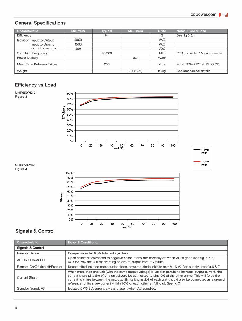
MHP1000 Series
• 1200 W High Line Output Power
• Rugged Industrial Construction
• Variable Speed Fan for Noise Reduction
• -40 °C to +70 °C Operation
• 5 V Standby
• AC OK, Remote On/Off and Active Current Share
• Screw Terminals
• 3 Year Warranty
The MHP1000 AC-DC power supply provides upto 1200 W of output power in a compact rugged mechanical package, suitable for a
range of medical applications.
The unit comprises of a main output with voltages from 12-48 VDC and a 5 VDC standby supply which can be utilitsed with the
signals and control features of the unit to provide detection of loss of AC input and remote on/off control.
Multiple units can be used in parallel via the current share facility, providing higher power solutions. Inherently low earth leakage
current, and conducted EMC compliance to Class B also simplify higher power system design.
Packaged in a compact 9.5” (241 mm) x 5.9” (150 mm) x 2.4” (61 mm) and carrying IEC60601 family safety approvals, the MHP1000
has a load dependant variable speed fan is fully protected with overtemperature shutdown and provides -40 ºC start up with full
power from -20 ºC to 50 ºC and 50% power at +70 ºC.

Figure 1
2
xppower.com
Input Characteristics
Input Derating Curve
Characteristic Minimum Typical Maximum Units Notes & ConditionsInput Voltage - Operating 85 115/230 264 VAC Derate output power < 90 VAC. See fig. 1.Input Frequency 47 50/60 63 Hz
Power Factor >0.9 EN61000-3-2 class A compliant
Input Current - No Load 0.35/0.5 A 115/230 VACInput Current - Full Load(1000 W) 10.9/5.3 A 115/230 VAC
Inrush Current 60 A 230 VAC cold start, 25 ºCEarth Leakage Current 75/140 250 µA 115/230 VAC/50 Hz (Typ.), 264 VAC/60 Hz (Max.)Input Protection T20 A/250 V internal fuse in both lines
Models and Ratings
Output Voltage V1Max Output Current V1
Standby Supply V2Max Output Power
Model Number<180 VAC >180 VAC <180 VAC >180 VAC
12 V 83.0 A 5 V / 1.0 A 1001 W MHP1000PS1215 V 67.0 A 5 V / 1.0 A 1010 W MHP1000PS1524 V 42.0 A 50.0 A 5 V / 1.0 A 1013 W 1200 W MHP1000PS2428 V 36.0 A 43.0 A 5 V / 1.0 A 1013 W 1200 W MHP1000PS2836 V 28.0 A 34.0 A 5 V / 1.0 A 1013 W 1200 W MHP1000PS3648 V 21.0 A 25.0 A 5 V / 1.0 A 1013 W 1200 W MHP1000PS48
9085 264
Input Voltage (VAC)
40
50
80
60
70
90
100
Out
put
Pow
er (%
)

xppower.com
3
Output Characteristics
Characteristic Minimum Typical Maximum Units Notes & ConditionsOutput Voltage - V1 12 48 VDC See Models and Ratings tableInitial Set Accuracy ±1 (V1) , ±5 (V2) % 50% load, 115/230 VACOutput Voltage Adjustment ±10 % V1 only. See mechanical details.Minimum Load 0 AStart Up Delay 0.5 s 230 VAC full loadHold Up Time 20 msDrift ±0.2 % After 20 min warm upLine Regulation ±0.5 % 90-264 VACLoad Regulation ±1 (V1) , ±5 (V2) % 0-100% load.
Transient Response - V1 4 % Recovery within 1% in less than 500 µs for a 50-75% and 75-50% load step
Ripple & Noise 1 % pk-pk V1: 20 MHz bandwidthOvervoltage Protection 115 145 % Vnom DC. Output 1 only, recycle input to resetOverload Protection 110 140 % I nom Output 1 only, auto reset. See fig 2.Short Circuit Protection Auto Recovery, hiccup modeTemperature Coefficient 0.02 %/˚COvertemperature Protection °C Protects unit from overtemperature. Auto reset.
Output Overload Characteristic
Figure 2Typical V1 Overload Characteristic (MHP1000PS12 shown)
024
68101214
0 5 10 15 20 25 30 35Output Current (A)
Out
put V
olta
ge (V
)
Unit entershiccup mode

xppower.com
Xxxxxxxxxx
4
General Specifications
Efficiency vs Load
Characteristic Minimum Typical Maximum Units Notes & ConditionsEfficiency 84 % See fig 3 & 4Isolation: Input to Output
Input to GroundOutput to Ground
4000 VAC1500 VAC500 VDC
Switching Frequency 70/200/130 kHz PFC converter / Main converter / StandbyPower Density 8.9 W/in3
Mean Time Between Failure 260 kHrs MIL-HDBK-217F at 25 ºC GB
Weight 2.1 (940) lb (g) See mechanical details
Signals & Control
MHP1000PS12Figure 3
Characteristic Notes & Conditions
Signals & Control
Remote Sense Compensates for 0.5 V total voltage drop
AC OK / Power FailOpen collector referenced to negative sense, transistor normally off when AC is good (see fig. 5 & 8)AC OK: Provides ≥ 5 ms warning of loss of output from AC failure
Remote On/Off (Inhibit/Enable) Uncommited isolated optocoupler diode, powered diode inhibits both V1 & V2 (fan supply) (see fig.6 & 9)
Current Share
When more than one unit (with the same output voltage) is used in parallel to increase output current, thecurrent share pins 5/6 of one unit should be connected to pins 5/6 of the other unit(s). This will force thecurrent to share between the outputs. Similarly pins 2/4 of each unit should also be connected as a groundreference. Units share current within 10% of each other at full load. See fig 7.
Standby Supply V2 Isolated 5 V/1.0 A supply, always present when AC supplied.
MHP1000PS48Figure 4

xppower.com
5
Figure 5
Figure 6
AC OK/Power Fail
Remote On/Off (Inhibit)
Signals & Control
AC OK Collector Pin 3
AC OK Emitter Pin 2 (-sense)
POWER SUPPLY
Transistor On (<0.8 V): AC NOT OKTransistor Off (>4.5 V): AC OK
J2 Logic Connector
330R
5 V Standby Return Pin 10
5 V Standby Pin 9
Max 12 V 20 mA
V):
V):
INHIBIT HI INHIBIT LOW
Inhibit Hi Pin 7
POWER SUPPLY
100 R
800 R
2-5 mA
Chassis J3 Logic Connector
Signal High: Power Supply OFF Low or Floating: Power Supply ON
Signal High: Power Supply ON Low or Floating: Power Supply OFF
Inhibit LoPin 8
5 V Standby Pin 9
5 V Standby Return Pin 10
Inhibit HiPin 7
POWER SUPPLY
100 R
Chassis J3 Logic Connector
Inhibit LoPin 8
5 V Standby Pin 9
5 V Standby Return Pin 10
800 R
2-5 mA
Signals - Parallel Load & Current Share Connection Example
- +
- + - + - +
V1 Output V1 Output V1 Output
- Sense
- Sen
se+ Sense
+ Sen
se
- S
ense
+ S
ense
CurrentShare
CurrentShare
MHP1000PSXX (1) MHP1000PSXX (2) MHP1000PSXX (3)
Load
Figure 7

xppower.com
6
AC OK Collector Pin 3
AC OK Emitter Pin 2
Power Supply 1
J3 Connector
330R
5 V Standby Return Pin 10
5 V Standby Pin 9
OK Emitter Pin 2
Power Supply 2
J3 Connector
AC OK Emitter Pin 2
Power Supply 3
J3 Connector
Transistor On (<0.8 V): AC NOT OKTransistor Off (>4.5 V): AC OK
AC OK Collector Pin 3
OK Collector Pin 3Figure 8
Parallel AC OK Connection
Parallel Remote Inhibit Connection
Figure 9
PSU 1 PSU 2 PSU 8
Pin 7
Pin 8
Pin 7
Pin 8
Pin 7
Pin 8
Please see figure 6.

xppower.com
Xxxxxxxxxx
7
Environmental
Temperature Derating Curve
Fan Speed Control
Characteristic Minimum Typical Maximum Units Notes & Conditions
Operating Temperature -20 +70 °C Derate linearly from +50 ºC at 2.5%/ºC to 50% at 70 ºC. See fig 10.
Low Temperature Start Up -40 °CSome specification parameters maybeexceeded until after 20 minutes warm upperiod.
Storage Temperature -40 +85 °C
Cooling 2 x integral variable speed fans load dependant. See fig 11.
Humidity 5 95 %RH Non-condensingOperating Altitude 3000 m
Shock3 x 30 g/11 ms shocks in both +ve & -ve directions along the 3 orthogonal axis, total 18 shocks.
Vibration Single axis 10-500 Hz at 2 g x 10 sweeps
Electromagnetic Compatibility - Immunity
Phenomenon Standard Test Level Criteria Notes & ConditionsLow Voltage PSU EMC EN61204-3 High severity level as belowHarmonic Current EN61000-3-2 Class AESD EN61000-4-2 3 ARadiated EN61000-4-3 3 AEFT EN61000-4-4 3 ASurges EN61000-4-5 Installation class 3 AConducted EN61000-4-6 3 A
Dips and Interruptions EN60601-1-2
Dip: 30% 25 AC Cycles ADip: 60% 5 AC Cycles A 230 VAC 100% load, 100 VAC 50% loadDip: 100% 0.5 AC Cyles AInt: >95% 5000 ms B
Figure 10
Figure 11
40
30
10
0
20
50
-20
Out
put
Pow
er (%
)
60
70
80
90
100
0 +20 +40 +50 +60 +70
Ambient Temperature (ºC)
0
50
0
Fan
Sp
eed
(%)
100
25 50 75 100
Output Power (%)

21-Feb-17
xppower.com
8
Electromagnetic Compatibility - Emissions Phenomenon Standard Test Level Criteria Notes & ConditionsConducted EN55011/22 Class BRadiated EN55011/22 Class AVoltage Fluctuations EN61000-3-3
Safety Agency Approvals
Safety Agency Safety Standard Category
CB Report Certificate #US/18260/UL, IEC60601-1 Ed 3 Including Risk Management MedicalUL UL File # E146893, ANSI/AAMI ES 60601-1:2005 & CSA C22.2 No. 60601-1:08 MedicalTUV TUV EN60601-1:2006 Medical
Equipment Protection Class Safety Standard Notes & Conditions
Class I IEC60601-1 Ed 3 See safety agency conditions ofacceptability for details
Mechanical Details
CL4.50
(114.3)
1.20 (30.5)
Pin 2 Pin 1
Pin 10 Pin 9
Detail A J3: Logic Connector
9.41 (238.9)
B B
B B
B B
4 x M4-0.7 THD both side faces0.15 (3.8) max screw penetrationmax torque 10.62 lbs-in (1.2 Nm)
4 x M4-0.7 THD both side faces0.15 (3.8) max screw penetrationmax torque 10.62 lbs-in (1.2 Nm)
Airflow
1.33 (33.8)
6.70 (170.2)
VO+
VO-
L
N
A
9.48 (240.9)
5.90(149.8)
2.91(73.9)
1.20 (30.5)
1.47(37.4)
9.55 (242.64)
2.40 (61.0)
V1 Adjustment
Output On, LED
Standard Terminal Block, M4 Screw3 Pins 0.37 (9.5) centerTorque 10.62 lbs-in (1.2 Nm)
Standard Terminal Block, M6 Screw, 4 Pins 0.62 (16.0) centerTorque 26.0 lbs-in (2.94 Nm)
Notes:1. Dimensions shown in inches (mm). 2. Weight: 2.8 lb (1.25 kg).
3. J3 Mating plug: JST part no. PHDR-10VS, contact: 26-22 AWG JST part no.SPHD-001T-P0.5.
J3 Logic Connector(JST B10B-PHDSS)
Pin Function1 + Sense2 - Sense3 AC OK/Power Fail4 - Sense5 Current Share6 Current Share7 + Inhibit8 - Inhibit9 +5 V Standby10 -5 V Standby
Means of Protection Category
Primary to Secondary 2 x MOPP (Means of Patient Protection)IEC60601-1 Ed 3
Primary to Earth 1 x MOPP (Means of Patient Protection)