MGS Speed Reducers and Gearmotors - … de serv e... · 40.150 End Cap 50.010 Output Shaft 50.070...
24
...new solutions MGS Speed Reducers and Gearmotors "S" Series Maintenance Manual ® DIST. AUTORIZADO MEX (55) 53 63 23 31 QRO (442) 1 95 72 60 MTY (81) 83 54 10 18 [email protected]
Transcript of MGS Speed Reducers and Gearmotors - … de serv e... · 40.150 End Cap 50.010 Output Shaft 50.070...
...new solutions
MGS Speed Reducersand Gearmotors
"S" SeriesMaintenanceManual
®
DIST. AUTORIZADOMEX (55) 53 63 23 31QRO (442) 1 95 72 60
MTY (81) 83 54 10 [email protected]

"S" Series – Right Angle Helical/Worm MGS ReducerInstallation Instructions
Thank you for purchasing a STOBER drive. In order toobtain long life and trouble-free operation from yourMGS speed reducer, it is essential that the installationand operating procedures outlined in this manual befollowed.This manual includes directions for mounting and start-up of the MGS unit, as well as lubrication and mainte-nance instructions. Failure to follow these instructionswill void the drive's warranty.The torque required by the application must not exceedthe reducer torque capacity shown on the nameplate.For safety purposes a safety coupling should beinstalled between the reducer and the driven load.Otherwise, overload may cause damage to the interiorparts of the reducer which may result in breaking thereducer housing. As a result, persons could be injuredby flying parts or splashing hot gear oil.If you have questions about the installation, operation ormaintenance of your MGS unit, please contact yourlocal STOBER distributor for assistance.
WARNING: Safety is the most important considerationwhen operating any type of drive. Through properapplication, safe handling methods, and wearingappropriate clothing, you can prevent accidents andinjury to yourself and fellow workers.The shafts of MGS speed reducers and gearmotorsrotate at very high speeds and can cut off or severelyinjure hands, fingers, and arms. Use appropriate guardsfor shafts and other rotating parts at all times. Follow alldirections in the service instruction manual. Obey allfederal, state and local safety regulations when operat-ing the drive.• Always be sure electrical power is off while making
electrical connections and during installation andmaintenance of the unit.
• Keep clothing, hands, and tools away from ventilationopenings on motors and from all rotating parts duringoperation.
• Lift drive with a double rope sling or other properlifting equipment of adequate strength. Make sure
load is secured and balanced to prevent shifting whenunit is being moved. Lifting drives by hand may bedangerous and should be avoided.
• The intended use of lifting lugs is to handle the weightof the unit only. Never use a lifting lug to lift attachedassemblies.
• Never operate drive at speeds higher than thoseshown on the nameplate, or personal injury mayresult. Contact STOBER Drives Inc., if there is anychange of operating conditions from those for whichthe unit was originally sold (as stamped on thenameplate). Failure to comply could result in personalinjury and or machinery damage.
• Always follow good safety practices at all times.Each drive is tested before delivery. Before installationhowever, it is advisable to examine the unit for possibledamage which might have occurred during transit. Ifdamage is discovered, it should be immediately re-ported to the transport agent.If installation is delayed after receipt of the MGS speedreducer, the drive should be stored in a clean, dry placeuntil put into service. Long term storage requires specialprocedures. If not kept in a heated, dry area, consultSTOBER Drives, Inc. for storage instructions.
NOTE: If it is necessary to clean drive shafts, take careto protect the oil seals.
IMPORTANT: Do not use any device to hammer theunit onto the output shaft during installation since thebearing races could be damaged.
1
WARNINGCover rotatingparts with safetyguard beforeturning onpower.
®
DIST. AUTORIZADOMEX (55) 53 63 23 31QRO (442) 1 95 72 60
MTY (81) 83 54 10 [email protected]

2
"S" Series – Right Angle Helical/Worm MGS ReducerLubrication and Mounting Data
Table No. 2 S102/S402 Plug Locations
Mounting Drain Plug and Vent LocationPosition 1 2 2a 3
EL1 Vent DrainEL2 Drain VentEL3 Vent DrainEL4 Drain VentEL5 Drain VentEL6 Vent Drain
Position 2a is on the opposite side of 2.
Table No. 3 S103/S403 Plug Locations
Mounting Drain Plug and Vent LocationPosition 1 2 2a 3
EL1 Vent DrainEL2 Drain VentEL3 Vent DrainEL4 Drain VentEL5 Drain VentEL6 Vent Drain
Position 2a is on the opposite side of 2.
MAINTENANCE:With STOBER reducers very little maintenance isrequired under normal operating conditions.
In the event an oil change is needed, completely drainthe reducer and replace with a compatible 5EP ratedlubricant. Check your lubrication supplier for a compa-rable lubricant.
LUBRICATION and MOUNTING POSITION:All STOBER units are shipped filled with the requiredamount of lubrication (Mobilgear 630) unless otherwisespecified.
The mounting positions and the required amount oflubricant for each position is shown on the followingpages. In order to provide the proper lubrication quantitythe position required must be specified at the time oforder.
No unit will be shipped without the mountingposition specified by the customer.
Vertical positions such as EL3 or EL4 may requiredifferent seals, bearings, etc. so it is very importantto mount the unit in the position for which it wasassembled.
Breathers are provided on all "S" series units. Thefollowing tables show the location of drain and ventplugs for each location.
← 3← 3← 3← 3← 3↑ 2↑ 2↑ 2↑ 2↑ 2
↓ 1↓ 1↓ 1↓ 1↓ 1
← 3← 3← 3← 3← 3↑ 2↑ 2↑ 2↑ 2↑ 2
↓ 1↓ 1↓ 1↓ 1↓ 1
®
DIST. AUTORIZADOMEX (55) 53 63 23 31QRO (442) 1 95 72 60
MTY (81) 83 54 10 [email protected]

3
Position EL1 Position EL2
Position EL5Table No. 5
Quantity of Lubricant
"A" Quantity
Module ozs. liters
S102 32 .95S202 64 1.90S203 74 2.10S302 101 3.00S303 115 3.28S402 149 4.40S403 169 4.8
"V" Quantity
Module ozs. liters
S102 32 .95S202 64 1.90S203 78 2.20S302 105 3.10S303 118 3.38S402 152 4.50S403 172 4.90
Position EL6
Position EL4Position EL3
"S" Series – Right Angle Helical/Worm MGS ReducerLubrication and Mounting Data
The unit shown has the shaft on Side 4 (left) in all drawings. Mounting position is not a description of shaft side extension.
Table No. 2
Quantity of LubricantModule Quantity
ozs. liters
S102 20 .6S202 41 1.2S203 47 1.4S302 74 2.2S303 85 2.5S402 118 3.5S403 135 4.0
Table No. 1Quantity of Lubricant
Module Quantity
ozs. liters
S102 17 .50S202 34 1.00S203 41 1.20S302 53 1.55S303 61 1.85S402 88 2.60S403 108 3.20
Table No. 3
Quantity of Lubricant
Module Quantity
ozs. liters
S102 20 .6S202 41 1.2S203 47 1.4S302 74 2.2S303 85 2.5S402 108 3.2S403 122 3.6
Table No. 4
Quantity of Lubricant
Module Quantity
ozs. liters
S102 20 .6S202 41 1.2S203 47 1.4S302 74 2.2S303 85 2.5S402 108 3.2S403 122 3.6
Table No. 6
Quantity of Lubricant
Module Quantity
ozs. liters
S102 24 .7S202 54 1.6S203 61 1.8S302 81 2.4S303 91 2.7S402 118 3.5S403 128 3.8
2
64
1
5
3
2
64
15
3
2
6
4
1
5
3
26
4
15
3
2
6
41
5
3
2
6
41
53
®
DIST. AUTORIZADOMEX (55) 53 63 23 31QRO (442) 1 95 72 60
MTY (81) 83 54 10 [email protected]
Location Description Location Description Location DescriptionNo. No. No.
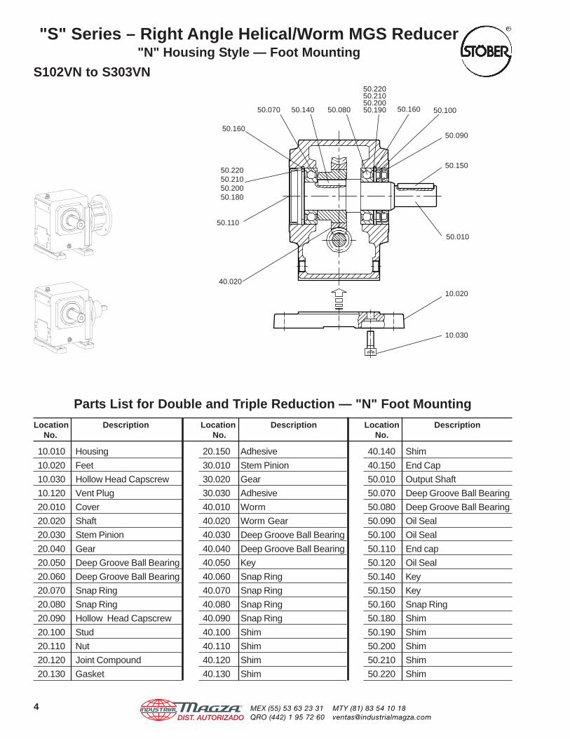
"S" Series – Right Angle Helical/Worm MGS Reducer"N" Housing Style — Foot Mounting
S102VN to S303VN
Parts List for Double and Triple Reduction — "N" Foot Mounting
10.010 Housing
10.020 Feet
10.030 Hollow Head Capscrew
10.120 Vent Plug
20.010 Cover
20.020 Shaft
20.030 Stem Pinion
20.040 Gear
20.050 Deep Groove Ball Bearing
20.060 Deep Groove Ball Bearing
20.070 Snap Ring
20.080 Snap Ring
20.090 Hollow Head Capscrew
20.100 Stud
20.110 Nut
20.120 Joint Compound
20.130 Gasket
20.150 Adhesive
30.010 Stem Pinion
30.020 Gear
30.030 Adhesive
40.010 Worm
40.020 Worm Gear
40.030 Deep Groove Ball Bearing
40.040 Deep Groove Ball Bearing
40.050 Key
40.060 Snap Ring
40.070 Snap Ring
40.080 Snap Ring
40.090 Snap Ring
40.100 Shim
40.110 Shim
40.120 Shim
40.130 Shim
40.140 Shim
40.150 End Cap
50.010 Output Shaft
50.070 Deep Groove Ball Bearing
50.080 Deep Groove Ball Bearing
50.090 Oil Seal
50.100 Oil Seal
50.110 End cap
50.120 Oil Seal
50.140 Key
50.150 Key
50.160 Snap Ring
50.180 Shim
50.190 Shim
50.200 Shim
50.210 Shim
50.220 Shim
50.110
50.22050.21050.20050.180
50.160
50.070 50.140 50.160 50.100
50.090
50.150
50.010
10.020
10.030
40.020
50.080
50.22050.21050.20050.190
4 ®
DIST. AUTORIZADOMEX (55) 53 63 23 31QRO (442) 1 95 72 60
MTY (81) 83 54 10 [email protected]

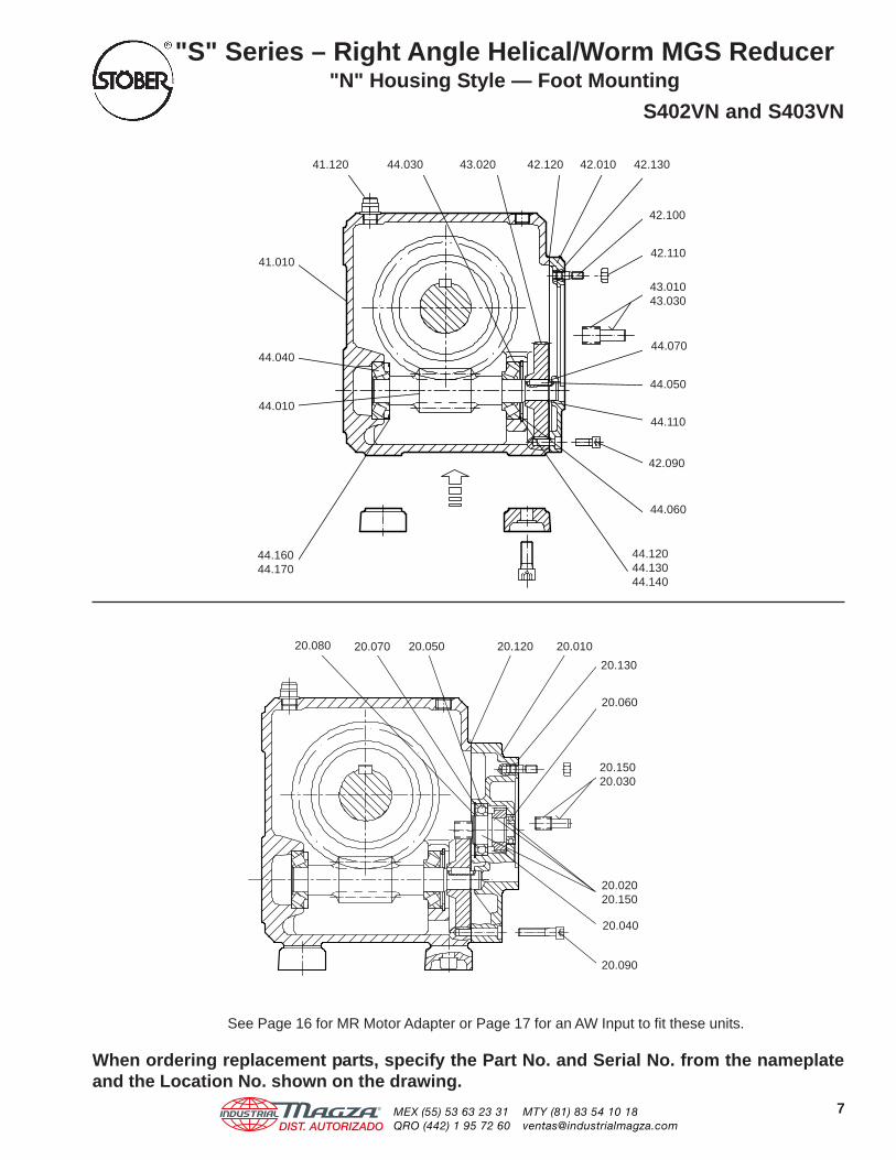
See Page 16 for MR Motor Adapter or Page 17 for an AW Input to fit these units.
When ordering replacement parts, specify the Part No. and Serial No. from the nameplateand the Location No. shown on the drawing.
"S" Series – Right Angle Helical/Worm MGS Reducer"N" Housing Style — Foot Mounting
S102VN to S303VN
20.090
40.090
40.070
40.100
40.010
40.150
40.060 40.050
30.01030.030
20.110
20.100
20.13010.120 20.01020.12030.02040.03010.010
40.040
20.15020.030
20.02020.150
20.040
20.060
20.01020.05020.12020.080 20.13020.070
40.12040.13040.14040.200
40.11040.080
20.090
5®
DIST. AUTORIZADOMEX (55) 53 63 23 31QRO (442) 1 95 72 60
MTY (81) 83 54 10 [email protected]

Location Description Location Description Location DescriptionNo. No. No.
"S" Series – Right Angle Helical/Worm MGS Reducer"N" Housing Style — Foot Mounting
S402VN and S403VN
10.030
40.020
50.110
50.160
50.010
10.020
50.070 50.140 50.080 50.160
50.22050.21050.20050.190 50.100
50.090
50.150
50.22050.21050.20050.180
Parts List for Double and Triple Reduction — "N" Foot Mounting
10.010 Housing
10.020 Feet
10.030 Hollow Head Capscrew
10.120 Vent Plug
20.010 Cover
20.020 Shaft
20.030 Stem Pinion
20.040 Gear
20.050 Deep Groove Ball Bearing
20.060 Deep Groove Ball Bearing
20.070 Snap Ring
20.080 Snap Ring
20.090 Hollow Head Capscrew
20.100 Stud
20.110 Nut
20.120 Joint Compound
20.130 Gasket
20.150 Adhesive
30.010 Stem Pinion
30.020 Gear
30.030 Adhesive
40.010 Worm
40.020 Worm Gear
40.030 Taper Roller Bearing
40.040 Taper Roller Bearing
40.050 Key
40.060 Snap Ring
40.070 Snap Ring
40.110 Shim
40.120 Shim
40.130 Shim
40.140 Shim
40.160 Nilos Ring
40.170 Lubricant
50.010 Output Shaft
50.070 Deep Groove Ball Bearing
50.080 Deep Groove Ball Bearing
50.090 Oil Seal
50.100 Oil Seal
50.110 End cap
50.120 Oil Seal
50.140 Key
50.150 Key
50.160 Snap Ring
50.180 Shim
50.190 Shim
50.200 Shim
50.210 Shim
50.220 Shim
6 ®
DIST. AUTORIZADOMEX (55) 53 63 23 31QRO (442) 1 95 72 60
MTY (81) 83 54 10 [email protected]
See Page 16 for MR Motor Adapter or Page 17 for an AW Input to fit these units.
When ordering replacement parts, specify the Part No. and Serial No. from the nameplateand the Location No. shown on the drawing.
"S" Series – Right Angle Helical/Worm MGS Reducer"N" Housing Style — Foot Mounting
S402VN and S403VN
20.01020.12020.080 20.070 20.050
20.090
20.02020.150
20.15020.030
20.130
20.040
20.060
41.120 44.030 43.020 42.010 42.130
42.100
42.110
43.01043.030
42.090
44.110
44.070
44.12044.13044.140
44.040
44.010
41.010
44.16044.170
42.120
44.050
44.060
7®
DIST. AUTORIZADOMEX (55) 53 63 23 31QRO (442) 1 95 72 60
MTY (81) 83 54 10 [email protected]

Location Description Location Description Location DescriptionNo. No. No.
"S" Series – Right Angle Helical/Worm MGS Reducer"F" Housing Style — Round Flange
S102VF to S303VF
30.020 Gear
30.030 Adhesive
40.010 Worm
40.020 Worm Gear
40.030 Deep Groove Ball Bearing
40.040 Deep Groove Ball Bearing
40.050 Key
40.060 Snap Ring
40.070 Snap Ring
40.080 Snap Ring
40.090 Snap Ring
40.100 Shim
40.110 Shim
40.120 Shim
40.130 Shim
40.140 Shim
40.150 Cap Plug
50.010 Output Shaft
50.020 Output Flange
50.070 Deep Groove Ball Bearing
50.080 Deep Groove Ball Bearing
50.090 Oil Seal
50.100 Oil Seal
50.110 Plug
50.140 Key
50.150 Key
50.160 Snap Ring
50.180 Shim
50.190 Shim
50.200 Shim
50.210 Shim
50.220 Shim
50.230 Hollow Head Capscrew
50.260 Sealant
Parts List for Double and Triple Reduction — "F" Housing Style
10.010 Housing
10.120 Vent Plug
20.010 Cover
20.020 Shaft
20.030 Stem Pinion
20.040 Gear
20.050 Deep Groove Ball Bearing
20.060 Deep Groove Ball Bearing
20.070 Snap Ring
20.080 Snap Ring
20.090 Hollow Head Capscrew
20.100 Stud
20.110 Nut
20.120 Joint Compound
20.130 Gasket
20.150 Adhesive
30.010 Stem Pinion
50.15050.090
50.070
50.110
50.160
50.010 50.20050.080 50.100 50.020
50.25050.16040.02050.140
50.22050.21050.20050.190
50.22050.21050.20050.180
8 ®
DIST. AUTORIZADOMEX (55) 53 63 23 31QRO (442) 1 95 72 60
MTY (81) 83 54 10 [email protected]
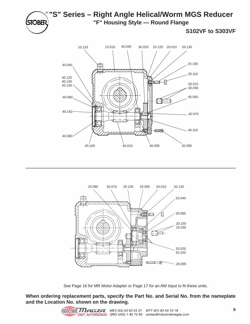
See Page 16 for MR Motor Adapter or Page 17 for an AW Input to fit these units.
When ordering replacement parts, specify the Part No. and Serial No. from the nameplateand the Location No. shown on the drawing.
"S" Series – Right Angle Helical/Worm MGS Reducer"F" Housing Style — Round Flange
S102VF to S303VF
40.050
10.120
40.060
40.150
40.100 40.010 40.090
40.080
20.090
40.110
40.070
30.01030.030
20.110
20.100
20.13020.12030.02040.03010.010
20.080
20.040
20.15020.030
20.060
20.13020.01020.05020.12020.070
20.02020.150
20.090
40.12040.13040.140
40.040
20.010
9®
DIST. AUTORIZADOMEX (55) 53 63 23 31QRO (442) 1 95 72 60
MTY (81) 83 54 10 [email protected]
Location Description Location Description Location DescriptionNo. No. No.
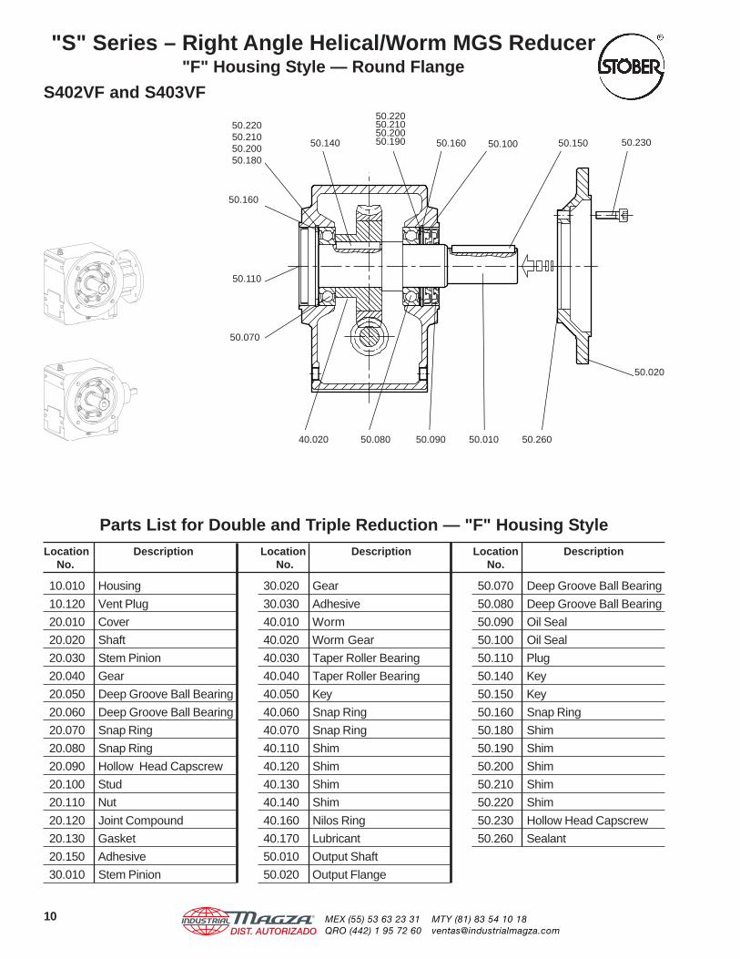
"S" Series – Right Angle Helical/Worm MGS Reducer"F" Housing Style — Round Flange
S402VF and S403VF
30.020 Gear
30.030 Adhesive
40.010 Worm
40.020 Worm Gear
40.030 Taper Roller Bearing
40.040 Taper Roller Bearing
40.050 Key
40.060 Snap Ring
40.070 Snap Ring
40.110 Shim
40.120 Shim
40.130 Shim
40.140 Shim
40.160 Nilos Ring
40.170 Lubricant
50.010 Output Shaft
50.020 Output Flange
50.070 Deep Groove Ball Bearing
50.080 Deep Groove Ball Bearing
50.090 Oil Seal
50.100 Oil Seal
50.110 Plug
50.140 Key
50.150 Key
50.160 Snap Ring
50.180 Shim
50.190 Shim
50.200 Shim
50.210 Shim
50.220 Shim
50.230 Hollow Head Capscrew
50.260 Sealant
Parts List for Double and Triple Reduction — "F" Housing Style
10.010 Housing
10.120 Vent Plug
20.010 Cover
20.020 Shaft
20.030 Stem Pinion
20.040 Gear
20.050 Deep Groove Ball Bearing
20.060 Deep Groove Ball Bearing
20.070 Snap Ring
20.080 Snap Ring
20.090 Hollow Head Capscrew
20.100 Stud
20.110 Nut
20.120 Joint Compound
20.130 Gasket
20.150 Adhesive
30.010 Stem Pinion
50.230
50.110
50.160
50.070
50.020
50.26050.01050.09050.08040.020
50.15050.10050.16050.140
50.22050.21050.20050.180
50.22050.21050.20050.190
10 ®
DIST. AUTORIZADOMEX (55) 53 63 23 31QRO (442) 1 95 72 60
MTY (81) 83 54 10 [email protected]

See Page 16 for MR Motor Adapter or Page 17 for an AW Input to fit these units.
When ordering replacement parts, specify the Part No. and Serial No. from the nameplateand the Location No. shown on the drawing.
"S" Series – Right Angle Helical/Worm MGS Reducer"F" Housing Style — Round Flange
S402VF and S403VF
20.01020.12020.080 20.070 20.050
20.090
20.02020.150
20.15020.030
20.130
20.040
20.060
10.120 40.030 30.020 20.01020.130
20.100
20.110
30.01030.030
20.090
40.110
40.07040.040
40.010
10.010
20.120
40.050
40.16040.170
40.12040.13040.140
40.060
11®
DIST. AUTORIZADOMEX (55) 53 63 23 31QRO (442) 1 95 72 60
MTY (81) 83 54 10 [email protected]

Location Description Location Description Location DescriptionNo. No. No.
"S" Series – Right Angle Helical/Worm MGS Reducer"G" Housing Style — Tapped Holes
S102AG to S303AG
Parts List for Double and Triple Reduction — "G" Tapped Holes
30.030 Adhesive
40.010 Worm
40.020 Worm Gear
40.030 Deep Groove Ball Bearing
40.040 Deep Groove Ball Bearing
40.050 Key
40.060 Snap Ring
40.070 Snap Ring
40.080 Snap Ring
40.090 Snap Ring
40.100 Shim
40.110 Shim
40.120 Shim
40.130 Shim
40.140 Shim
40.150 Cap Plug
50.010 Output Quill
50.050 Keeper Plate
50.070 Deep Groove Ball Bearing
50.080 Deep Groove Ball Bearing
50.090 Oil Seal
50.100 Oil Seal
50.110 Oil Seal
50.120 Oil Seal
50.140 Key
50.160 Snap Ring
50.170 Snap Ring
50.180 Shim
50.190 Shim
50.200 Shim
50.210 Shim
50.220 Shim
50.250 Roll Pin
50.280 Plug
10.010 Housing
10.120 Vent Plug
20.010 Cover
20.020 Shaft
20.030 Stem Pinion
20.040 Gear
20.050 Deep Groove Ball Bearing
20.060 Deep Groove Ball Bearing
20.070 Snap Ring
20.080 Snap Ring
20.090 Hollow Head Capscrew
20.100 Stud
20.110 Nut
20.120 Joint Compound
20.130 Gasket
20.150 Adhesive
30.010 Stem Pinion
30.020 Gear
50.140 50.080 50.16050.160
50.120
50.11050.090
50.280
50.050
50.250
50.01050.170
50.070
50.19050.20050.21050.220
50.22050.21050.20050.180
50.100
50.280
50.170
40.020
See Page 20 for hollow output installation instructions.
12 ®
DIST. AUTORIZADOMEX (55) 53 63 23 31QRO (442) 1 95 72 60
MTY (81) 83 54 10 [email protected]

See Page 16 for MR Motor Adapter or Page 17 for an AW Input to fit these units.
When ordering replacement parts, specify the Part No. and Serial No. from the nameplateand the Location No. shown on the drawing.
"S" Series – Right Angle Helical/Worm MGS Reducer"G" Housing Style — Tapped Holes
S102AG to S303AG
20.080
20.040
20.15020.030
20.02020.150
20.060
20.13020.01020.05020.12020.070
20.090
30.020
20.090
40.110
40.070
40.050
30.01030.030
10.120 10.010
20.100
20.110
20.13020.01020.120
40.09040.040 40.010 40.030
40.100
40.150
40.060
40.12040.13040.140
40.080
13®
DIST. AUTORIZADOMEX (55) 53 63 23 31QRO (442) 1 95 72 60
MTY (81) 83 54 10 [email protected]

Location Description Location Description Location DescriptionNo. No. No.
Parts List for Double and Triple Reduction — "G" Tapped Holes
30.030 Adhesive
40.010 Worm
40.020 Worm Gear
40.030 Taper Roller Bearing
40.040 Taper Roller Bearing
40.050 Key
40.060 Snap Ring
40.070 Snap Ring
40.110 Shim
40.120 Shim
40.130 Shim
40.140 Shim
40.160 Nilos Ring
40.170 Lubricant
50.010 Output Quill
50.050 Keeper Plate
50.070 Deep Groove Ball Bearing
50.080 Deep Groove Ball Bearing
50.090 Oil Seal
50.100 Oil Seal
50.110 Oil Seal
50.120 Oil Seal
50.140 Key
50.160 Snap Ring
50.170 Snap Ring
50.180 Shim
50.190 Shim
50.200 Shim
50.210 Shim
50.220 Shim
50.250 Roll Pin
50.280 Plug
10.010 Housing
10.120 Vent Plug
20.010 Cover
20.020 Shaft
20.030 Stem Pinion
20.040 Gear
20.050 Deep Groove Ball Bearing
20.060 Deep Groove Ball Bearing
20.070 Snap Ring
20.080 Snap Ring
20.090 Hollow Head Capscrew
20.100 Stud
20.110 Nut
20.120 Joint Compound
20.130 Gasket
20.150 Adhesive
30.010 Stem Pinion
30.020 Gear
50.160 50.070
"S" Series – Right Angle Helical/Worm MGS Reducer"G" Housing Style — Tapped Holes
S402AG and S403AG
50.140 40.020
50.19050.20050.21050.220
50.280
50.090
50.100
50.08050.160
50.01050.170
50.280
50.110
50.120
50.170
50.22050.21050.20050.180
5.250
50.050
See Page 20 for hollow output installation instructions.
14 ®
DIST. AUTORIZADOMEX (55) 53 63 23 31QRO (442) 1 95 72 60
MTY (81) 83 54 10 [email protected]

See Page 16 for MR Motor Adapter or Page 17 for an AW Input to fit these units.
When ordering replacement parts, specify the Part No. and Serial No. from the nameplateand the Location No. shown on the drawing.
"S" Series – Right Angle Helical/Worm MGS Reducer"G" Housing Style — Tapped Holes
S402AG and S403AG
20.080 20.070
20.15020.030
20.060
20.090
20.040
20.02020.150
20.130
20.01020.12020.050
10.120 10.010
40.040
40.010
30.020
30.01030.030
40.030 40.12040.13040.140
40.060
20.090
40.050
40.070
44.110
20.110
20.100
20.01020.120
20.130
40.16040.170
15®
DIST. AUTORIZADOMEX (55) 53 63 23 31QRO (442) 1 95 72 60
MTY (81) 83 54 10 [email protected]
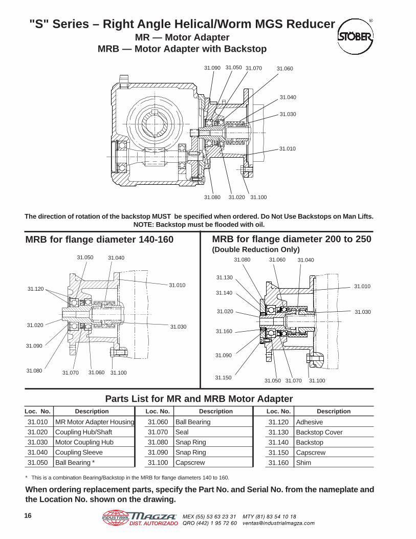
"S" Series – Right Angle Helical/Worm MGS ReducerMR — Motor Adapter
MRB — Motor Adapter with Backstop
MRB for flange diameter 140-160 MRB for flange diameter 200 to 250(Double Reduction Only)
31.080
31.090
31.020
31.120
31.04031.050
31.010
31.030
31.10031.070 31.060
Parts List for MR and MRB Motor AdapterLoc. No. Description Loc. No. Description Loc. No. Description
31.010 MR Motor Adapter Housing
31.020 Coupling Hub/Shaft
31.030 Motor Coupling Hub
31.040 Coupling Sleeve
31.050 Ball Bearing *
31.060 Ball Bearing
31.070 Seal
31.080 Snap Ring
31.090 Snap Ring
31.100 Capscrew
31.120 Adhesive
31.130 Backstop Cover
31.140 Backstop
31.150 Capscrew
31.160 Shim
* This is a combination Bearing/Backstop in the MRB for flange diameters 140 to 160.
When ordering replacement parts, specify the Part No. and Serial No. from the nameplate andthe Location No. shown on the drawing.
31.160
31.090
31.150
31.010
31.030
31.130
31.140
31.020
31.070 31.10031.050
31.04031.06031.080
16
The direction of rotation of the backstop MUST be specified when ordered. Do Not Use Backstops on Man Lifts.NOTE: Backstop must be flooded with oil.
31.060
31.040
31.030
31.010
31.10031.080
31.07031.05031.090
31.020
®
DIST. AUTORIZADOMEX (55) 53 63 23 31QRO (442) 1 95 72 60
MTY (81) 83 54 10 [email protected]

41.01041.150
41.080 41.030 41.040 41.060
41.090
41.100
41.150
41.140 41.010
41.020
41.05041.04041.03041.080
41.060
Parts List for AW and AWB Input ShaftLocation Description Location Description Location Description
No. No. No.
* This is a combination Bearing/Backstop in the AWB for flange diameters 140 to 160.
When ordering replacement parts, specify the Part No. and Serial No. from the nameplate andthe Location No. shown on the drawing.
AWB for flange diameter 200 to 250(Double Reduction Only)
AWB for flange diameter 140-160
The direction of rotation of the backstop MUST be specified when ordered. Do Not Use Backstops on Man Lifts.NOTE: Backstop must be flooded with oil.
41.050
41.020
41.010 Input Housing
41.020 Shaft
41.030 Ball Bearing *
41.040 Ball Bearing
41.050 Key
41.060 Seal
41.070 Seal
41.080 Snap Ring
41.090 Backstop Cover
41.100 Backstop
41.110 Capscrew
41.120 Shim
41.130 Key
41.140 Snap Ring
41.150 Adhesive
"S" Series — Right Angle Helical/Worm MGS ReducerAW — Input Shaft
AWB — Input Shaft with Backstop
17
41.080 41.010
41.050
41.020
41.04041.030 41.070
41.060
®
DIST. AUTORIZADOMEX (55) 53 63 23 31QRO (442) 1 95 72 60
MTY (81) 83 54 10 [email protected]

18
MGS ReducerMotor Adapter Installation
Step 2.Locate the Motor Coupling on the Motor Shaft
Mount the coupling with the hub projection toward the step orshoulder of the motor. The motor shaft should project through thecoupling by the "X" dimension (or the value determined using theprevious measurement).
Table No. 2 Location of Motor Coupling
Adapter "X" "X" Adapter "X" "X"Part No. mm inches Part No. mm inches
MR140/050 28 1.1 MR250/210 46 1.8MR160/050 22 .9 MR300/180 10 .4MR160/140 25 1.0 MR300/210 26 1.0MR200/050 12 .5 MR300/250 42 1.7MR200/140 12 .5 MR300/280 58 2.3MR200/180 30 1.2 MR350/320 64 2.5MR250/180 30 1.2 MR350/360 80 3.1
"X" Tolerance – +1mm / -0mm (+0.040 / -0.000 inches)
Step 3. Tighten the Setscrew
With the coupling hub located at the correct distance, tightenthe setscrew in the coupling.
Step 1. Measure the Motor Shaft
Accurate measurement of the motor shaft is vital to mounting themotor coupling correctly. The measurement must be taken fromthe face of the motor or pilot surface (see above) to the end of themotor shaft. If this dimension is the same as the NEMA standard"AH" dimension shown in Table No. 1, proceed with the motormounting in Step 2.
Table No. 1 NEMA Motor Shaft Dimensions
Motor "AH" Shaft Motor "AH" ShaftFrame Dia. Frame Dia.
56C 21/16 5/8 254/256TC 33/4 15/8
143/145TC 21/8 7/8 284/286TC 43/8 17/8
182/184TC 25/8 11/8 324/326TC 5 21/8
213/215TC 31/8 13/8 364/365TC 55/8 23/8
If the motor shaft length measurement is less than "AH", subtractthe difference ( 1) from the "X" dimension shown in Table No. 2.
If the motor shaft length measurement is greater than "AH", addthe difference ( 2) to the "X" dimension shown in Table No. 2.
56C - 145TC 182TC - 365TC
AH56C - 145TC
1
2
X
X- 1
X+ 2
AH182TC - 365TC
®
DIST. AUTORIZADOMEX (55) 53 63 23 31QRO (442) 1 95 72 60
MTY (81) 83 54 10 [email protected]

19
MGS ReducerMotor Adapter Installation
Step 5. Mount the Motor
With the coupling secure, insert the motor shaft into the motoradapter. The coupling sleeve is already installed on the matingreducer coupling hub inside the motor adapter. The sleeveshould move freely in an axial direction. (Axial displacement±.040 inches.)
With the motor in place, tighten the motor bolts.
Step 4. Secure the Motor Shaft Key
For ease of installation, secure the motor shaft key. Staking nearthe end of the keyway, on the sides of the key, or a temporaryadhesive works well.
Some motor manufacturers provide a drain hole in the mountingface of washdown motors. In some mounting positions, water orother material can enter the motor adapter and fail the bearing.
Caution: If the motor coupling is not installed correctly, the input bearing may fail due to pre-load. This will void the warranty of the reducer and possibly fail the motor.
Be sure this hole is covered during washing or when the unit is ina wet environment. The illustration shows the method that Stoberassembly personnel use to plug the hole.
®
DIST. AUTORIZADOMEX (55) 53 63 23 31QRO (442) 1 95 72 60
MTY (81) 83 54 10 [email protected]
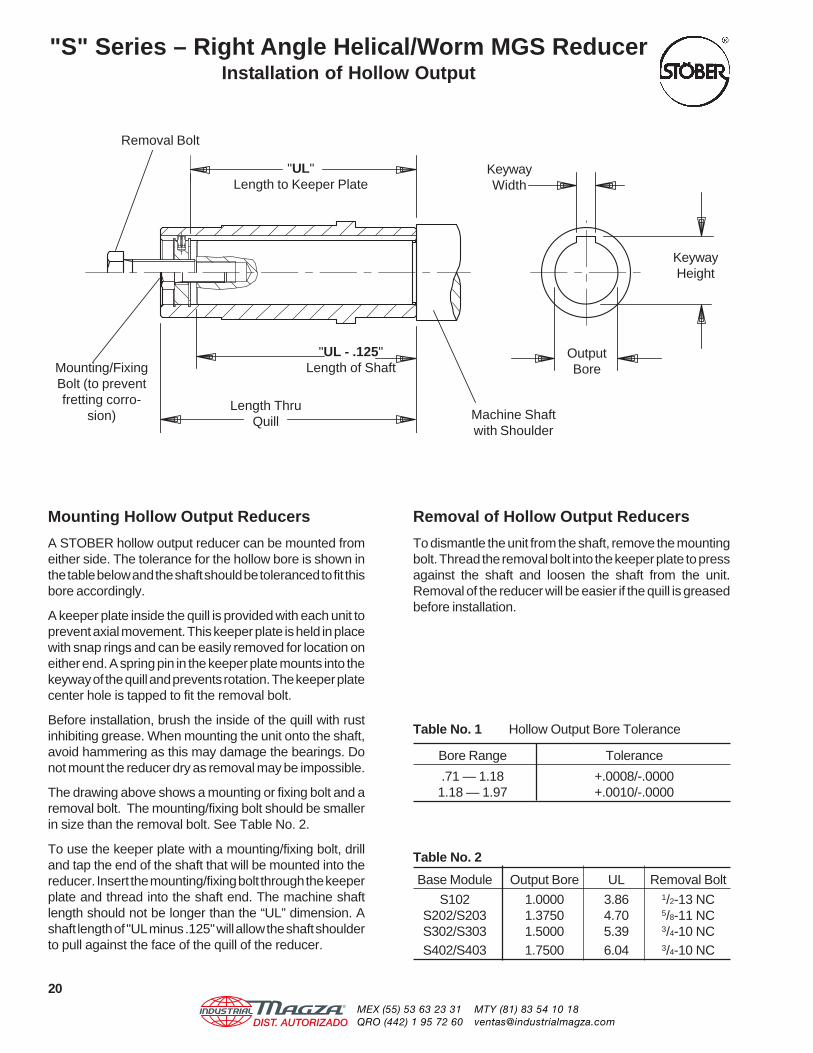
"S" Series – Right Angle Helical/Worm MGS ReducerInstallation of Hollow Output
Mounting Hollow Output Reducers
A STOBER hollow output reducer can be mounted fromeither side. The tolerance for the hollow bore is shown inthe table below and the shaft should be toleranced to fit thisbore accordingly.
A keeper plate inside the quill is provided with each unit toprevent axial movement. This keeper plate is held in placewith snap rings and can be easily removed for location oneither end. A spring pin in the keeper plate mounts into thekeyway of the quill and prevents rotation. The keeper platecenter hole is tapped to fit the removal bolt.
Before installation, brush the inside of the quill with rustinhibiting grease. When mounting the unit onto the shaft,avoid hammering as this may damage the bearings. Donot mount the reducer dry as removal may be impossible.
The drawing above shows a mounting or fixing bolt and aremoval bolt. The mounting/fixing bolt should be smallerin size than the removal bolt. See Table No. 2.
To use the keeper plate with a mounting/fixing bolt, drilland tap the end of the shaft that will be mounted into thereducer. Insert the mounting/fixing bolt through the keeperplate and thread into the shaft end. The machine shaftlength should not be longer than the “UL” dimension. Ashaft length of "UL minus .125" will allow the shaft shoulderto pull against the face of the quill of the reducer.
Removal of Hollow Output Reducers
To dismantle the unit from the shaft, remove the mountingbolt. Thread the removal bolt into the keeper plate to pressagainst the shaft and loosen the shaft from the unit.Removal of the reducer will be easier if the quill is greasedbefore installation.
Table No. 2
Base Module Output Bore UL Removal Bolt
S102 1.0000 3.86 1/2-13 NCS202/S203 1.3750 4.70 5/8-11 NCS302/S303 1.5000 5.39 3/4-10 NCS402/S403 1.7500 6.04 3/4-10 NC
Table No. 1 Hollow Output Bore Tolerance
Bore Range Tolerance
.71 — 1.18 +.0008/-.00001.18 — 1.97 +.0010/-.0000
KeywayWidth
KeywayHeight
OutputBore
"UL - .125"Length of Shaft
Length ThruQuill
Mounting/FixingBolt (to preventfretting corro-
sion)
Removal Bolt
Machine Shaftwith Shoulder
"UL"Length to Keeper Plate
20®
DIST. AUTORIZADOMEX (55) 53 63 23 31QRO (442) 1 95 72 60
MTY (81) 83 54 10 [email protected]

1. GENERAL. All orders for products supplied bySTOBER DRIVES INC. (“STOBER”) shall be subject tothese terms and conditions of sales. All transactionsshall be governed by the laws of the Commonwealth ofKentucky. No modifications hereto will be binding unlessagreed to in writing by STOBER.
2. CUSTOMER. The term “Customer,” as used herein,means the distributor, resale dealer, original equipmentmanufacturer or first end-user customer that purchasesthe STOBER products.
3. WARRANTY. STOBER products shall be free fromdefects in material and workmanship for a maximum of5-years (single shift operation or 30 months multiple shiftoperation) for ServoFit products; 3-years (single shiftoperation or 18 months multiple shift operation) for MGSproducts; 2-years (single shift operation or 12 monthsmultiple shift operation) for TD products, from the date ofshipment to the Customer. For ServoFit products, allnormal wear items, including oil seals and bearings,shall be covered for a period of 2-years (single shiftoperation or 12 months multiple shift operation). In theevent that a product proves to be defective, STOBER’ssole obligation shall be, at its option, to repair or replacethe product. The repaired or replacement product will beshipped F.O.B. STOBER’s facilities, freight prepaid bySTOBER.
No employee, agent or representative of STOBER hasthe authority to waive, alter, vary or add to the termshereof without the prior written approval of an officer ofSTOBER. It is expressly agreed that (a) this sectionconstitutes the final expression of the parties’understanding with respect to the warranty and (b) thissection is a complete and exclusive statement of theterms of the warranty.
STOBER shall have no obligation under the warranty setforth above in the event that:
(a) The Customer fails, within the warranty period tonotify STOBER in writing and provide STOBER withevidence satisfactory to STOBER of the allegeddefect within five (5) days after it becomes known tothe customer;
(b) After inspection of a product, STOBER determines,in its sole discretion, that it is not defective inmaterial or workmanship;
(c) Repair or replacement of a product is requiredthrough normal wear and tear;
(d) Any part in a product or any ingredient contained ina product requires replacement or repair throughroutine usage or normal wear and tear;
(e) A product is not maintained or used in accordancewith STOBER’s applicable operating and/ormaintenance manuals, whether by the Customer orany third party;
(f) A product has been subject to misuse,misapplication, negligence, neglect (including, butnot limited to, improper maintenance or storage),accident, catastrophe, improper installation,modification, adjustment, repair or lubrication,whether by the Customer or any third party, withoutthe prior written consent of STOBER. Misuse shallinclude, but not be limited to, deterioration in aproduct due to chemical action and wear caused bythe presence of abrasive materials;
(g) The system of connected rotating parts into whichthe product becomes incorporated is not compatiblewith the product, or it is not free from critical speedor torsional or other type of vibration within thespecified operating range, no matter how induced;or
(h) The transmitted load and imposed torsional thrustand overhung loads are not within the publishedcapacity limits for the unit sold.
Items manufactured by other parties but installed in oraffixed to STOBER’s products are not warranted bySTOBER and bear only those warranties, express orimplied, which are given by the manufacturer of suchitems, if any.
THE WARRANTY SET FORTH ABOVE IS INTENDEDSOLELY FOR THE BENEFIT OF THE Customer ANDDOES NOT APPLY TO ANY THIRD PARTY. ALLCLAIMS MUST BE MADE BY THE Customer AND MAYNOT BE MADE BY ANY THIRD PARTY. THISWARRANTY MAY NOT BE TRANSFERRED ORASSIGNED, IN WHOLE OR IN PART, BY THE CustomerFOR ANY REASON WHATSOEVER. ANY SUCHATTEMPTED TRANSFER OR ASSIGNMENT SHALLBE NULL AND VOID.
THIS WARRANTY TAKES THE PLACE OF ALL OTHERWARRANTIES, EXPRESS OR IMPLIED, WHICH AREHEREBY DISCLAIMED AND EXCLUDED BY STOBER,INCLUDING WITHOUT LIMITATION, ANY WARRANTYOF MERCHANTABILITY OR FITNESS FOR APARTICULAR PURPOSE OF USE AND ALLOBLIGATIONS OR LIABILITIES ON THE PART OFSTOBER FOR DAMAGES ARISING OUT OF OR INCONNECTION WITH THE USE, REPAIR ORPERFORMANCE OF THE PRODUCTS.
4. MODIFICATIONS. STOBER reserves the right,without notice to the Customer, to (a) change thespecifications of any product, (b) improve a product inany manner that STOBER deems necessary orappropriate and (c) discontinue the manufacture of anyproduct.
5. PURCHASE ORDERS. The Customer will submitpurchase orders for the products to STOBER in writing,whether by mail or telefax, which shall set forth, at aminimum: (a) an identification of the products ordered,(b) prices for such products, (c) quantities, (d) requesteddelivery dates and (e) shipping instructions and shippingaddresses.
6. ACCEPTANCE OF ORDERS. All purchase ordersreceived from the Customer are subject to acceptanceby STOBER in writing.
7. MODIFICATION OF ORDERS. No acceptedpurchase order shall be modified or canceled exceptupon the written agreement of STOBER and theCustomer. Mutually agreed cancellations shall be subjectto reasonable charges based upon expenses alreadyincurred by STOBER and commitments made bySTOBER. Mutually agreed change orders shall besubject to all provisions of these Terms and Conditionsof Sale.
8. PRICE INCREASES. STOBER may increase itsprices for the products by providing the original purchaserof the products with at least thirty (30) days’ prior writtennotice. Increased prices for products shall not apply topurchase orders accepted prior to the effective date ofthe price increase unless such orders provide for deliverymore than thirty (30) days after the date of acceptanceof the order.
9. PRICING AND DELIVERY TERMS. In accordancewith KRS 355.2-319(1)(b), all products are deliveredF.O.B. STOBER's warehouse facility in Maysville,Kentucky, or such other facility as STOBER maydesignate. Orders are then shipped per Customer'sshipping instructions as set forth in Customer's purchaseorder. CATALOG PRICING DOES NOT INCLUDESHIPPING, HANDLING AND TAXES. Once deliveredto a common carrier of the Customer's choosing [or ofSTOBER's choosing if Customer has failed to specify acommon carrier on or before five (5) days prior to therequested delivery date] STOBER shall have no furtherresponsibility for the products and all risk of damage,loss or delay shall pass to the Customer. A handling feeis added to freight costs by STOBER to cover the cost ofhaving to pay the carrier within seven (7) days when theterms with the Customer are net 30. The Customer hasthe option of shipping collect with our carrier or thecarrier of choice.
10. PAYMENT TERMS. Net 30 days. All orders will beshipped either prepaid by the Customer or C.O.D., atSTOBER’s option, unless the Customer has establisheda previously approved credit line. If STOBER approvesa credit line for the Customer, all payments shall be duewithin thirty (30) days of the date of the invoice. If anyinvoice is not paid in full within such thirty (30) day period,
then finance charges shall be assessed at the rate of oneand one-half percent (11/2%) per month (eighteen percent(18%) per year). If such rate is deemed to be usuriousat any time, it shall be reduced to the maximum ratepermitted by applicable law. STOBER may stop orwithhold shipment of products if the Customer does notfulfill its payment obligations. If STOBER is insecureabout payment for any reason, STOBER may require fullor partial payment in advance and as a condition to thecontinuation of its delivery of products.
11. SECURITY INTEREST. Unless and until theproducts are paid for in full, STOBER reserves a securityinterest in them to secure the unpaid balance of thepurchase price. The Customer hereby grants to STOBERa power of attorney, coupled with an interest, to executeand file on behalf of the Customer all necessary financingstatements and other documents required or appropriateto protect the security interest granted herein.
12. ACCEPTANCE OF PRODUCTS. The Customerwill conduct any incoming inspection tests as soon aspossible upon arrival of the products, but in no eventlater than ten (10) days after the date of receipt. Anyproducts not rejected by written notice to STOBERwithin such period shall be deemed accepted by theCustomer. STOBER shall not be liable for any additionalcosts, expenses or damages incurred by the Customer,directly or indirectly, as a result of any shortage, damageor discrepancy in a shipment.
13. LIMITATION OF REMEDIES.(a)STOBER SHALL NOT BE LIABLE FOR ANY
LOSS OR DAMAGE CAUSED BY DELAY INFURNISHING THE CUSTOMER WITHPRODUCTS.
(b)IN NO EVENT SHALL STOBER’S LIABILITYINCLUDE ANY SPECIAL, INDIRECT,INCIDENTAL OR CONSEQUENTIAL LOSSESOR DAMAGES, EVEN IF STOBER HAS BEENADVISED OF THE POSSIBILITY OF SUCHPOTENTIAL LOSS OR DAMAGE.
14. MADE-TO-ORDER PRODUCTS. STOBERreserves the right to revoke and amend any pricequotations offered to the Customer for made-to-orderproducts, provided that such price quotations have notbeen accepted by the Customer prior to the date ofrevocation or amendment.
15. DIES, TOOLS AND EQUIPMENT. Chargesincurred by the Customer for dies, tools and otherequipment shall not confer ownership or the right topossession therein by the Customer. All such dies, toolsand equipment shall remain the property of STOBER,and STOBER shall have the exclusive right to possessionthereof. STOBER shall maintain such tools andequipment in good working order.
16. REGULATORY LAWS AND STANDARDS.STOBER makes no representation that its productsconform to state or local laws, ordinances, regulations,codes or standards except as may be otherwise agreedto in writing by STOBER.
17. SIZES AND WEIGHTS. STOBER’s products aremade only in the sizes and to the specifications set forthin its catalogs and other literature. If any alteration isrequested, such altered product will be treated as amade-to-order item. STOBER assumes no responsibilityfor typographical errors which may appear in its catalogsor literature, and cannot accept alteration charges causedby such errors. Since weights shown in STOBER’scatalogs are approximate, they cannot be used indetermining freight allowances set forth in its catalogsand other literature. Freight allowances will be determinedat the time of shipment and shall be based on actualshipping weight.18. SYSTEM DESIGN. Responsibility for system designto ensure proper use and application of STOBER’sproducts within their published specifications and ratingsrests solely with the Customer. This includes, but is notlimited to, an analysis of loads created by torsionalvibrations within the entire system, regardless of howinduced.
Terms and Conditions of Sale
®
DIST. AUTORIZADOMEX (55) 53 63 23 31QRO (442) 1 95 72 60
MTY (81) 83 54 10 [email protected]
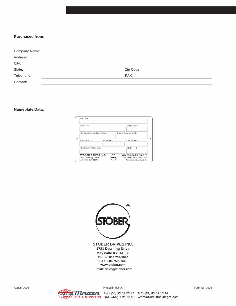
Purchased from:
Company Name:
Address:
City:
State: Zip Code
Telephone: FAX:
Contact:
Nameplate Data:
STOBER DRIVES INC.1781 Downing DriveMaysville KY 41056Phone: 606 759-5090FAX: 606 759-5045www.stober.com
E-mail: [email protected]
August 2006 Printed in U.S.A. Form No. 2003
Part No.
Serial No. Date Code
Oil Capacity in Ozs./Liters Output Torque in./lb.
Input HP/kW Input RPM Output RPM
Customer Information Ratio : 1
STOBER DRIVES INC. www.stober.com1781 Downing Drive Toll Free: 888 726-2371Maysville KY 41056 Assembled in U.S.A.
®
DIST. AUTORIZADOMEX (55) 53 63 23 31QRO (442) 1 95 72 60
MTY (81) 83 54 10 [email protected]