MGLV6120 SAIF (Q4) - CABLE CLEATS, CABLE JOINTS, CABLE TERMINATIONS, CABLE · PDF...
36
SAIF Switched and insulated fusegear For indoor/outdoor low voltage distribution up to 3200A
Transcript of MGLV6120 SAIF (Q4) - CABLE CLEATS, CABLE JOINTS, CABLE TERMINATIONS, CABLE · PDF...

SAIF Switched and insulated fusegearFor indoor/outdoor low voltage distribution up to 3200A


An introduction 4
Benefits 6
Low voltage options 8
Package substations 9
Fuse switching 10
Features and operation 12
Operation and disconnectors 14
Equipment types 16
The right fusegear for your application 18
MoD Defence Estates applications 20
Accessories 22
General technical information 25
Selection guide and mountings 30

SAIF: an introduction
Merlin Gerin SAIF offers a unique range of switchable fusegear, providing low voltage distribution for applications up to 3200A.
For indoor or outdoor use, SAIF is factory assembled in a choice of product to provide safe solutions for low voltage distribution, with the added benefit of minimum maintenance.
SAIF achieves levels of operator safety unmatched in other ranges of fusegear.Operator protection to IPXXB is maintained in all operating conditions, includingfuselink replacement when the pillar is live.
Since its launch, SAIF’s unique qualities have proved successful in marketsaround the world, being extensively used in commercial and public sector buildings and on a vast number of MoD Defence Estates.
...................................................................................................................................................................4

The market leader in fusegear, offering optimum levels of safety
SAIF provides choice of product range
SAIF is factory assembled and can be incorporated into the following configurations:
Outdoor feeder pillarOutdoor fuse cabinetIndoor fuseboard
With easy installation, high safety levels and modular technology, SAIF enables fast product delivery. The plug in feature of SAIF enables new circuits to be easily added to meet future requirements.
SAIF offers diverse solutions for low voltage distribution.
Outdoor feeder pillar
Outdoor fuse cabinet
Indoor fuseboard
................................................................................................................................................................... 5

SAIF: offers significant benefits
The innovation of SAIF brings benefits over and above traditional designs of fusegear. It has the safety and switching ability comparable to fuse switchboards manufactured to form 4, achieving optimum levels of safety and segregation.
Manufactured in one complete moulding, the SAIF fuseway offers segregation between phases
Safety levels over and above conventional designs of fusegearSAIF delivers personnel protection to IPXXB in all operating conditions. SAIF has the ability to protect the operator from contact with live parts innormal service and operating conditions.
Protection is maintained when fully shrouded fuse carriers are switched toeither ‘ON’ or ‘OFF’ positions, or completely removed from the three polefuseway. Fully shrouded fuse carriers held within a fully shrouded three polefuseway provide additional protection.
...................................................................................................................................................................6

Fault make, load break switchingSAIF achieves fault make, load break switching with the use of a portable, independent manual switching mechanism, providing through-fault capabilityup to 50kA. SAIF eliminates the need for isolation of the HV supply.
Offering easy operation, the robust switching mechanism and disconnectorsare fully interlocked to ensure correct operation and does not rely on the skill of the operator, or the speed at which the handle is turned. SAIF provides certified switching to IEC 60947-3.
Fully transferable across all fuse carriers, once the mechanism is in position, interlocks are defeated and the fuse carrier can be safely switched to the‘ON’ or ‘OFF’ position. The status of each fuse carrier is clearly indicated.
Versatility for future needsIncorporated into feeder pillar, fuse cabinets and fuseboards, SAIF offers ease of provision for future circuits, enabling additional fuseways to be simply plugged onto existing busbars to meet future needs and minimising costly downtime.
Easy installation, low maintenanceThe robust construction of SAIF withstands all weather conditions, providing high levels of performance. Simple installation and minimum maintenance is achieved by the arrangement of the cables at the base of each fuseway. This allows for pre-determined cable cores to be cut, providing easy termination.
SafetyCorrect operation is ensured at all times with interlocking between thefuseway and fusecarrier. This is achieved by preventing the fuse carrier being moved from one state to another without the means of the spring assisted switching mechanism.
DurabilityFixed and moving contacts within the SAIF fuseway, carriers and busbar are silver-plated to give extended contact life. All non-metallic components are manufactured from flame retardant materials.
Future upgradesUpgrades are easy. Plug-in features permit the addition or replacement of feeder circuits without the need for insulated tools.
Safe switching at a SAIFfeeder pillar
................................................................................................................................................................... 7

SAIF offers a range of low voltage selections for indoor and outdoor use
Direct mounting via flange to transformer; or free-standing and cable connectedBusbar systems and disconnectors up to 3200ADual busbar systems with load shedding facilities- Essential busbar up to 1600A- Non-essential up to 1000A through contactor
Choice of fuseway ratings: 400A, 630A or 800ACombined circuit breaker and fuseways incorporating- Moulded case circuit breakers up to 1600A- Air circuit breakers up to 3200A
A wide selection of metering solutions and accessoriesFacilities for safe connection of standby generators
Industry standards
SAIF meets the following industry standards and has obtained approval from the Electricity Association:
EA technical specification 37-2 issue 4Safety and switching levels comparable to switchboard built to form 4 of IEC 60439-1 Operator protection to IPXXB of IEC 60529Fault make, break switching certified to IEC 60947-316th Edition IEE regulations for switchgear forming part of an installation BS 7671: 2001Total quality assurance to ISO 9001Environmentally accredited to ISO 14001.
SAIF: low voltage options
As an assembled product
Easily accessible terminations at base of fuseway
...................................................................................................................................................................8

Package substations
One-stop… one contact… one complete package.
Merlin Gerin provides one-stop engineered packaged substations,tailored to customer requirements using products from our comprehensive range of distribution transformers, MV switchgearand LV equipment.
All of which can be managed by PowerLogic software, that allows communication, monitoring and control, giving an ‘intelligent’ package substation solution.
Substations are tailored to customer requirements using productsfrom our comprehensive range of distribution transformers, MVswitchgear and LV equipment.
Features and benefits
Simple specification
Factory assembled
Variety of MV/LV options
Flexible, tailored configurations to customer needs
Single lift arrangements
Directly mounted switchgear
Choice of arrangements of terminations
Operator protected
Minimised costs
................................................................................................................................................................... 9

The equipment consists of three phase fuseway moulding that accommodates busbar, fuse carriers and solid copper outgoing connections for cable termination
Sectionalised fuseway with type 630 BS fuse carriers ‘OFF’ (top), ‘ON’ (centre) and removed (bottom). ‘L’ section busbars at left.
SAIF: fuse switching
Illustrates when the fuse is in the‘OFF’ position interlock prevents it being inserted unless theswitching mechanism is used.
Plug-in busbar contacts.
Indication labels ensure the position of any fuse carrier can be determined at a glance.
Solid copper outgoing connectionscan accommodate cable lugs ormechanical connectors.
L1
L2
L3
...................................................................................................................................................................10

Safety features
SegregationEach fuse of the fuseway is segregated into a single pole fuse switch disconnector complete with arc chutes. Each outgoing cable termination is supplied complete with flexible PVC shroud.
Fault make/load break switchingAchieved by using the spring assisted mechanism, when fitted onto the fuseway moulding at each fuse position. This locks onto the bosses on the side walls and at the same time engages the fuse carrier drive arms. It cannot be operated until it is correctly positioned.
Cost effective low maintenance
Choice of standard fusesFuse carriers use standard distribution type gU with wedgetightening contacts IEC60269-2-1 section fuselinks.
DurabilityThe fixed and moving contacts within SAIF ways, carriers and busbar connections are silver plated for extended life and reduced maintenance.
Reduced costsThe switching mechanism can be stored with the unit, or issuedto operators for use across several SAIF units.
Future upgradesPlug-in features permit the addition or replacement of feeder circuits without the need for insulated tools.
Security
Full interlocking between the fuseway and the spring mechanism preventsany carrier being moved from ‘ON’ to ‘OFF’ position or vice versa except by use of the transferable switching mechanism.
SAIF fuse carriers Type 630BS92mm centres
Type 400BS82mm centres
................................................................................................................................................................... 11
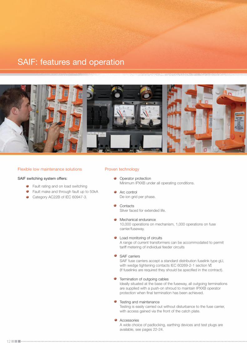
SAIF: features and operation
Proven technology
Operator protectionMinimum IPXXB under all operating conditions.
Arc controlDe-ion grid per phase.
ContactsSilver faced for extended life.
Mechanical endurance10,000 operations on mechanism, 1,000 operations on fuse carrier/fuseway.
Load monitoring of circuitsA range of current transformers can be accommodated to permit tariff metering of individual feeder circuits
SAIF carriersSAIF fuse carriers accept a standard distribution fuselink type gU, with wedge tightening contacts IEC 60269-2-1 section(If fuselinks are required they should be specified in the contract).
Termination of outgoing cablesIdeally situated at the base of the fuseway, all outgoing terminations are supplied with a push-on shroud to maintain IPXXB operator protection when final termination has been achieved.
Testing and maintenance Testing is easily carried out without disturbance to the fuse carrier, with access gained via the front of the catch plate.
AccessoriesA wide choice of padlocking, earthing devices and test plugs are available, see pages 22-24.
Flexible low maintenance solutions
SAIF switching system offers:
Fault rating and on load switching Fault make and through fault up to 50kACategory AC22B of IEC 60947-3.
...................................................................................................................................................................12

Drive cylinder
Interlock lever
A
Closedposition
Closedposition
Tilt upwards and withdraw
Fuse carrier interlock
Fuse carrier
Open position
................................................................................................................................................................... 13
Easy operation of the switching mechanism
Fuse carriers are switched using the transferable independent manual springassisted switching mechanism, operated as follows:
1 Hold mechanism top and bottom, and pull interlock lever in direction to A.
2 Move the mechanism forwards and down onto the locating bosses, drive cylinder engages the fuse carrier. The Interlocks on the fuse carrier will bereleased and position controlled by the drive cylinder.
3 Release the interlock lever to secure the mechanism, the handle can now be rotated.
4 To close circuit, rotate mechanism handle 90 degrees clockwise.
5 To open rotate anti-clockwise.
6 Reverse procedure for removal of mechanism.

SAIF: operation and disconnectors
Operating the disconnector
Fuse carriers are switched using the transferable independent manual springassisted switching mechanism, operated as follows:
1 Insert operating handle and rotate 180 degrees anti-clockwise, releasing contact pressure.
2 With the handle still in position hinge the front down to the isolated position.
3 Rotate handle 180 degrees clockwise to lock disconnector open and free handle.
4 Remove the handle.
Note: to close a disconnector use the reverse procedure to opening.
...................................................................................................................................................................14

CLOSED
CAM LO
KEY FREE
CAM FREEKEY TRAPPED
A range of current transformers can be accommodated within the disconnector.
Fully insulated designensures IPXXB operatorprotection.
Position indication labels.
Interlocks ensure correct contact pressure is obtainedbefore the operating handle can be removed.
An operating handle is provided with each unit.
SAIF disconnectors provide a point of
isolation per phase. Manufactured as
single-phase units, they are mounted as
standard in a vertical three phase and
neutral assembly. The disconnector can
contain a C.T. for transformer load
monitoring.
Protection from live conductors
Disconnectors are fully shrouded to protect the operator from live conductors. Safety is further enhanced by restricting the opening and closing of the unit by the use of a special insulated operating handle.
The disconnector and operating handle are fully interlocked to ensure theremoval of the handle only when the contact is fully closed and lockedclosed, or fully open and locked open.
Features
Type 3000 - Type 2000 - Type 1000Rated up to 3200AStandard plate tin (Suffix T) or silver-plated (Suffix S) refer to page 27 for free air ratingsFully shrouded to IPXXB, IEC 60529 Cable connected or direct through flange to transformerNeutrals are rated at 50% of phase rating - as standardHorizontal configuration available for special applicationsFor on load switching other options are available:SAIF fuseways up to 800AMoulded case circuit breakers up to 1600AAir circuit breakers up to 3200AWide selection of current transformer ratios, class and burden- refer to page 27 for further information
Test probe access
................................................................................................................................................................... 15

SAIF: equipment types
Busbars do not rely on the outgoing SAIF ways for mechanical support asthey are independently mounted and supported within the steel enclosure.
Plug-in contacts between the SAIF ways and busbar allow partly equippedunits to be added to later. Operator protection is provided when these sections are not in use, by an integral blanking plate.
Outdoor fuse cabinet with choice of fuseways
Fuse cabinets offer a choice of up to seven outgoing fuseways with anincoming disconnector, or a combination of fuseways and mccb's up to1600A.
SAIF enclosures and structural items are electrostatically treated to produce asuperior gloss finish, complying fully with all industrial standards. The strong outdoor weatherproof enclosure is IP33 ingress protected and is only flange connected to the transformer.
For easy access, fuse cabinets have removable front cross members.
Supplied as a range of products to suit LV requirements,SAIF offers easy upgrade for system needs.
SAIF is available as cabinets, pillars and boards in arange of sizes, types 2500, 1600 and 800, that determines the type and rating of disconnectors andbusbars used within any particular unit.
...................................................................................................................................................................16

Outdoor feeder pillar with circuit breaker option
Flexibility is provided by the option of circuit breakers as incoming devices.Feeder pillars can be either transformer mounted with up to 15 outgoing SAIF fuseways or free-standing with 14 outgoing fuseways and cable connected.
Feeder pillars are manufactured to IP33 ingress protection as standard with the option for IP54 through the use of door gaskets and filtered ventilation.
Indoor fuseboard with option of transformer, wall or floor mounted
Fully shrouded to provide IPXXB operator protection from live conductors, afuseboard can be either transformer, wall, or floor mounted with the option for the fuseways to accept outgoing cables from either above or below.Fuseboards offer the flexibility of choice of instrumentation, accessories and incoming/outgoing circuit requirements.
Factory assembled products are customised to suit a diverse range of LV distribution applications, indoor and outdoor.
................................................................................................................................................................... 17

New and replacement installations
There are two types of fusegear available from MerlinGerin, that provide compliance with the ‘Electricity atWork’ Regulations. These are Shielded and SAIF typeunits.
There are significant differences between the two.
Shielded
This type of equipment will provide IPXXB protection with the doors of the pillar open and all the fuse handles in place. The major drawback of Shielded equipment is the operational limitations. Although it is possible to safely check the readings of any metering etc; for an operation as simple as changingfuses the operator is exposed to live copperwork. Insertion or removal of thefuse handle is reliant on the skill and dexterity of the operator to minimise contact arcing or resist the possible force a fault condition could produce. Toavoid risk and guarantee compliance with regulation 14 of ‘Electricity atWork’, it is necessary to isolate the supply from the HV switchgear andensure no back feeds exist, prior to removal of the fuse handle.
SAIF
Superior to all other types of fusegear in that it provides IPXXB operator protection in all operating conditions, that includes fuse replacement with the pillar live. The transferable, switching mechanism provides a proven faultmake and through fault capability up to 50KA. It is fully interlocked to ensurecorrect on-load operation.
An operator opening the doors of SAIF equipment cannot accidentally touchlive metal whether the fuses are switched to the ‘ON’ or ‘OFF’ position, completely removed, or whether the disconnector is open or closed. It is notnecessary to isolate the HV supply or check for back feeding as with Shieldedpattern equipment. As SAIF is the only fusegear that can be assumed to meetregulation 14 under all circumstances, in addition to its many other benefits, itis being selected for new and replacement applications.
SAIF: the right fusegear for your application
...................................................................................................................................................................18

SAIF: choice, flexibility, protection
SAIF is increasingly being used with circuit breakers to provide greater flexibility for LV distribution.
With traditional substations, transformer overload protection is provided by themedium voltage unit on the primary side of the transformer. If the overload isone phase of the LV then the protection provided by the MV is minimal.Therefore in networks where loadings are not very predictable, this can be anunacceptable situation. An incoming circuit breaker can provide genuine overload protection and be able to switch the total LV load in a single, safeoperation, whilst the circuit breaker protects the transformer from prematureageing due to persistent overloading.
Outgoing circuit breakers offer better flexibility and protection especially where a large LV supply is required.
Merlin Gerin range of air and moulded case circuit breakers are rated from250A to 3200A when combined within the LV feeder pillar with SAIF fusewaysand disconnectors.
Pendennis Castle, Falmouth, Cornwall
A popular tourist attraction managed by English Heritage, Pendennis Castle
was built during the reign of Henry VIII. It was subsequently extended and remained in
military use until the 1950s.
A Merlin Gerin SAIF 4-way free-standing outdoor feeder pillar, rated to 800A, has updated
the castle’s electrical distribution system, as part of a project to upgrade its electrical
distribution, telecommunications and sub-distribution systems.
The feeder pillar feeds most parts of the castle, including an area called the
Half Moon Battery and its observation post, used during World War II, and the
Elizabethan East Bastion.
“Safety, quality of construction and ease of use were primary considerations in the choice
of equipment,” comments consulting engineer Alan Traynor of Hoare, Lee and Partners.
“Flexibility was also a factor in that additional circuits can be readily added to the unit in
the future, if required.”
SAIF in all climates
SAIF is a worldwide solution, extensively used on Hong Kong Island where itensures security of supply in a busy commercial centre.
Safe and reliable
Six SAIF feeder pillars have been installed in Bristol hospital, providing low voltage supplies to the hospital wards and operating theatres.
Pendennis Castle
Hong Kong
Bristol Hospital
................................................................................................................................................................... 19

SAIF: MoD Defence Estates application
General existing installations
Many MoD Defence Estates have been supplied in the past with conventionaldesigns of feeder pillars.
These are the most basic form of fusegear and expose the operator to liveconductors when the equipment doors are open.
The introduction of the ‘Electricity at Work’ Regulations place greater restrictions when working on, or near live conductors (Regulation 14).
The effect of the Regulations has meant that to avoid the risk of prosecutionin the event of an accident, the entire feeder pillar must be isolated and madedead before opening the doors.
Many MoD Defence Estates have had to replace the conventional designs offeeder pillars and choose Merlin Gerin SAIF for its optimum levels of supply.
...................................................................................................................................................................20
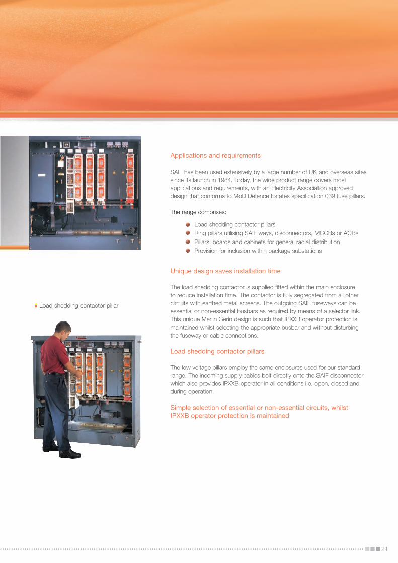
Applications and requirements
SAIF has been used extensively by a large number of UK and overseas sitessince its launch in 1984. Today, the wide product range covers most applications and requirements, with an Electricity Association approveddesign that conforms to MoD Defence Estates specification 039 fuse pillars.
The range comprises:
Load shedding contactor pillars Ring pillars utilising SAIF ways, disconnectors, MCCBs or ACBs Pillars, boards and cabinets for general radial distribution Provision for inclusion within package substations
Unique design saves installation time
The load shedding contactor is supplied fitted within the main enclosure to reduce installation time. The contactor is fully segregated from all other circuits with earthed metal screens. The outgoing SAIF fuseways can beessential or non-essential busbars as required by means of a selector link.This unique Merlin Gerin design is such that IPXXB operator protection ismaintained whilst selecting the appropriate busbar and without disturbing the fuseway or cable connections.
Load shedding contactor pillars
The low voltage pillars employ the same enclosures used for our standardrange. The incoming supply cables bolt directly onto the SAIF disconnectorwhich also provides IPXXB operator in all conditions i.e. open, closed andduring operation.
Simple selection of essential or non-essential circuits, whilst IPXXB operator protection is maintained
Load shedding contactor pillar
................................................................................................................................................................... 21

SAIF: accessories
A wide range of accessories can be integrated to customise SAIF units to meet specific cabling and operational needs
Neutrals
One neutral terminal point is provided for each SAIF way, located on the neutral busbar assembly.
Horizontal movement of the terminal provides easier crossover of the cores, facilitated by direct connection of the normal cable to the neutral busbar.Removable neutral links can be supplied.
Colour
Dark Grey shaded 632 of BS 381C is supplied as standard. Other colours are available upon request.
Cable terminations
Blank gland plates are supplied as standard unless specified otherwise and/or in the absence of cable details. Cable terminations to suit all types and sizes of cable can be provided subject to the maximum sizes given on page 26.
Various termination arrangements are available that include split mechanical cable clamps, PVC shrouds, compression glands or wiping glands. Cable endsockets are not included, but can be supplied if specified.
Cabinets, pillars and boards are supplied with flexible PVC shrouds to provideindividual shrouding and segregation for each terminal.
Bolted neutral link instead of direct cable connection to neutral busbar
Mechanical cable clamp instead ofbolt for cable lug, for 3 or 4 core cables, 70 - 300mm2
PVC cable shrouds for use withcable lugs
PVC cable shroud for use with cable clamps
...................................................................................................................................................................22

Operating equipment
Storage brackets for the transferable fuse switch mechanism and the disconnector operating handle are incorporated in all units as standard.Door trays are also available for additional storage within an enclosure.
Street lighting
Comprising of a contactor and back-up fuses contained in a segregate compartment and controlled by either a time switch or photo electric cell.
Current transformers
Incoming and outgoing current transformers (CT’s) are encapsulated in epoxyresin within moulded cases, complying with IEC60044 (pt1). Test certificates indicating ratio error and phase angle are available uponrequest for classes 1.0 and 0.5. For information on ratio, class and burden see page 27.
Internal lights
Fuse protected with manual or door operated switches.
Anti-condensation heaters
Supplied through a fuse with an option of manual or thermostatic control.
Padlocking devices
PDO: For padlocking feeder circuits with fuse carriers removed.PDI: For padlocking feeder circuits with fuse carriers in situ. It has the
advantage of retaining fuse holders when device is attached, preventing damage or loss of fuse holders when no suitable storage is available.
PDH: For padlocking horizontally mounted disconnectors. Can be fitted with disconnector open or closed.
PDV: For padlocking vertically mounted disconnectors. Can be fitted with disconnector open or closed. Padlocks not included.
PDP: For padlocking a single phase of a SAIF fuseway with carrier removed.
PDT: For padlocking all three phases of a vertical mounted disconnector in open position.
Sectionalised SAIF disconnector showing integral CT
SAIF way CT
Three phase padlocking devicePart no. PDI - fuse carriers in situ
Padlocking device Part no.PDO - fuse carriersremoved
Three phase incoming disconnector padlocking device.Part no. PDT
Padlocking device.Part no. PDP - single fuse carrierremoved
................................................................................................................................................................... 23

Test plugs
For attaching test devices such as fault make MCCB’s or other test equipment to outgoing cables and/or busbars. Supplied with a 2m cable.
Type Application
TP4 Type 400 way
TP6 Type 630 way
TP6 Type 800 way
Earthing devices
Universal earthing devices offer busbar or circuit earthing on SAIF fuseway.
Application Type Fault rating
Type 400 fuseway ED4 18.0kA 0.5secs.
Type 630 fuseway ED6 35.5kA 0.5secs.
Type 800 fuseway ED6 35.5kA 0.5secs.
Incoming earthing devices
Incoming device allows for easy installation without the need for insulated tools to earth the incoming cable cores.
Busbar rating Type
800A INC-ED-SA 800
1600A INC-ED SA 1600
This incoming earthing device can only be installed on fusegear manufactured to the DEO specification 039 fuse pillars manufactured after December 1998.
Instrument panels
Each unit is fitted with an integral instrument panel that can accommodate a variety of instruments and fittings. Where none is specified, the panel will be left empty.
SAIF: accessories
TP6 attached to type 630 fuseway
Earthing device ED6
Incoming earthing deviceINC-ED-SA
Instrument panelTo customer specification
...................................................................................................................................................................24

SAIF fuseways
Fuseway types 800 630 400
Fuse carrier type 800BS 630BS 400BS
Current rating (A) 800 630 400
Operator protection IPXXB IPXXB IPXXB
Minimum distance between centres 160 120 120of ways of the same rating (mm)
Approx. weight (kg) 10.0 9.7 8.0
Free air rating of SAIF fuseways
Type Fuse fitted Current rating (A) at ambient temperature (ºC)35º 40º 45º 50º 55º 60º 65º
800BS 800A 800 770 730 685 640 595 540
630BS 630A 630 630 625 600 570 535 490
400BS 400A 400 390 370 350 330 305 275
SAIF disconnectors
SAIF: general technical information
Details Type3000S 3000T 2000S 2000T 1000S 1000T
Rated insulation voltage (V) 690 690 690 690 690 690
Free air current rating-single phase 3752 3367 2720 2520 1595 1455IEC 60947-3 and BSEN 60947-3
Short time current withstand (kA)
Degree of protection BS 60529
Isolation distance (mm)
Weight, single pole (kg)
60 for 1.0s40.0 for 3.0s
IPXXB
19
8.7
60 for 1.0s35.5 for 3.0s
IPXXB
19
6.4
35.5 for 1.0s18.0 for 3.0s
IPXXB
19
4.0
................................................................................................................................................................... 25

General technical specification of SAIF fuseways
Details 800BS 630BS 400BS
Rated insulation voltage (V) 690 690 690
Rated operational voltage (V) 415 415 415
Rated operational current to category 800 630 400of duty AC22B of IEC 60947-3 and BSEN 60947-3
Rated operational performance in accordance with 2400 at 436V 1890 at 456V 1200 at 485VAC22B of IEC 60947-3 and BSEN 60947-3 & 0.65 p.f. & 0.65 p.f. & 0.65 p.f.Tested load make and break current (A)
Rated fused short circuit current 50 50 50Through fault and make onto faultSingle pole IEC 60947-3 and BSEN 60947-3
Rated fused short circuit current 50 50 50Three phase through fault IEC 60439 (kA)
Rated fuse short circuit making capacity with 25 25 18 solid links instead of fuses IEC 60947-3 and BSEN 60947-3
Rated fuse short time withstand current with solid 25 for 25 for 18 for links instead of fuses IEC 60947-3 0.5 seconds 0.5 seconds 0.5 seconds
Degree of protection, IEC 60529 IPXXB IPXXB IPXXB
Maximum cable to be accommodated 2 x 4C240with standard terminals (mm2) 1 x 4C300 1 x 4C300 1 x 4C300
1 x SC630
Minimum distance between centre 200 120 120of ways with same rating (mm)
Minimum distance between centre of ways 240 140 140of same rating with bolted neutral link (mm)
Isolation distance (double break) (mm) 12+12 12+12 12+12
SAIF: general technical information
...................................................................................................................................................................26

SAIF carriers
Carrier types 800BS 630BS 400BS
Current rating (A) 800 630 400
Fuse type IEC60269 IEC60269 IEC60269-2-1 SECT VI -2-1 SECT VI -2-1 SECT VI(92mm) (92mm) (82.5mm)
Fuse range 20-800 20-630 20-400
Weight (kg) 1.8 1.4 1.0
Free air rating of SAIF disconnectors
Type Current rating (A) at ambient temperature (ºC)35º 40º 45º 50º 55º 60º 65º
3000S 3752 3597 3437 3271 3098 2917 2728
3000T 3367 3224 3076 2921 2759 2588 2408
2000S 2720 2630 2530 2420 2300 2180 2030
2000T 2520 2420 2310 2200 2060 1920 1760
1000S 1595 1540 1485 1420 1340 1260 1170
1000T 1455 1400 1330 1265 1200 1125 1045
Current transformers: ratios, class and burden
Ratio---/5 Burden (VA) at accuracy classApplication Class 5.0 Class 3.0 Class 1.0 Class 0.5
Ways Disconnectors200
200 200/400250
250 250/500300
300 300/600400
400 400/800500
500 500/100600
600 600/1200800
800800/1600
10001000/2000
120016002000
1200/240024003000
Available Not available
2.5 5.0 7.5 10 15 2.5 5.0 7.5 10 15 2.5 5.0 7.5 10 15 2.5 5.0 7.5 10 15
................................................................................................................................................................... 27

Rating of SAIF equipment
Equipment Enclosure Equipment Disconnector Current rating (A) at ambient temperature (ºC)arrangement protection type
35º 40º 45º 50º 55º 60º
Pillar IP33 2400*† 3000S 3160 3037 2910 2780 2646 2508
3000T 2780 2646 2508 2365 2216 2060
1600 2000S 2100 2000 1900 1790 1650 1510
2000T 1805 1700 1600 1490 1375 1260
800 1000S 1340 1290 1240 1150 1065 970
1000T 1185 1125 1065 1000 935 860
IP54 2400* 3000S 2814 2693 2570 2444 2314 2181
3000T 2444 2314 2181 2044 1903 1756
1600 2000S 1950 1880 1780 1635 1550 1400
2000T 1730 1635 1540 1425 1300 1175
800 1000S 1220 1135 1065 1000 945 890
1000T 1065 1010 955 905 850 800
Board IPXXB 2400* 3000S 3235 3091 2943 2790 2631 2466
3000T 2871 2733 2591 2433 2290 2130
1600 2000S 2250 2130 2025 1920 1815 1715
2000T 1920 1815 1715 1616 1520 1420
800 1000S 1400 1340 1285 1215 1110 1010
1000T 1225 1165 1100 1035 975 910
Cabinet IP33 1600 2000S 2150 1975 1830 1705 1600 1510
2000T 1705 1600 1510 1425 1350 1270
800 1000S 1220 1105 1025 960 900 835
1000T 1050 985 935 880 825 770
* Ratings apply for incoming disconnector in centre only.
† Higher ratings available upon request.
SAIF: general technical information
...................................................................................................................................................................28
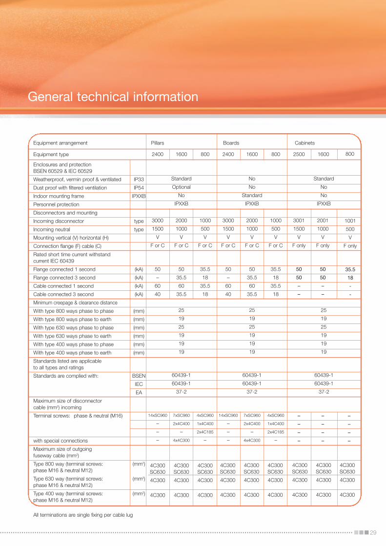
General technical information
Equipment arrangement Pillars Boards Cabinets
Equipment type
Enclosures and protection BSEN 60529 & IEC 60529
Weatherproof, vermin proof & ventilated IP33
Dust proof with filtered ventilation IP54
Indoor mounting frame IPXXB
Personnel protection
Disconnectors and mounting
Incoming disconnector type
Incoming neutral type
Mounting vertical (V) horizontal (H)
Connection flange (F) cable (C)
Rated short time current withstand current IEC 60439
Flange connected 1 second (kA)
Flange connected 3 second (kA)
Cable connected 1 second (kA)
Cable connected 3 second (kA)
Minimum creepage & clearance distance
With type 800 ways phase to phase (mm)
With type 800 ways phase to earth (mm)
With type 630 ways phase to phase (mm)
With type 630 ways phase to earth (mm)
With type 400 ways phase to phase (mm)
With type 400 ways phase to earth (mm)
Standards listed are applicable to all types and ratings
Standards are complied with: BSEN
IEC
EA
Maximum size of disconnector cable (mm2) incoming
Terminal screws: phase & neutral (M16)
with special connections
Maximum size of outgoing fuseway cable (mm2)
Type 800 way (terminal screws: (mm2)phase M16 & neutral M12)
Type 630 way (terminal screws: (mm2)phase M16 & neutral M12)
Type 400 way (terminal screws: (mm2)phase M16 & neutral M12)
All terminations are single fixing per cable lug
50
–
60
40
50
35.5
60
35.5
35.5
18
35.5
18
50
–
60
40
50
35.5
60
35.5
35.5
18
35.5
18
50
50
–
–
50
50
–
–
3000
1500
V
F or C
2000
1000
V
F or C
1000
500
V
F or C
3000
1500
V
F or C
2000
1000
V
F or C
1000
500
V
F or C
3001
1500
V
F only
2001
1000
V
F only
4C300SC630
4C300
4C300
4C300SC630
4C300
4C300
4C300SC630
4C300
4C300
14xSC960
–
–
–
7xSC960
2x4C400
–
4x4C300
4xSC960
1x4C400
2x4C185
–
14xSC960
–
–
–
7xSC960
2x4C400
–
4x4C300
4xSC960
1x4C400
2x4C185
–
–
–
–
–
–
–
–
–
60439-1
60439-1
37-2
60439-1
60439-1
37-2
60439-1
60439-1
37-2
Standard
No
No
IPXXB
No
No
Standard
IPXXB
Standard
Optional
No
IPXXB
25
19
25
19
19
19
25
19
25
19
19
19
25
19
25
19
19
19
2400 1600 800 2400 1600 800 2500 1600
1001
500
V
F only
800
35.5
18
-
-
–
–
–
–
4C300SC630
4C300
4C300
4C300SC630
4C300
4C300
4C300SC630
4C300
4C300
4C300SC630
4C300
4C300
4C300SC630
4C300
4C300
4C300SC630
4C300
4C300
................................................................................................................................................................... 29

SAIF Feeder Pillar - Standard Distribution
Dimensions (mm) Maximum number of outgoing SAIF fuseways with incoming cable connected disconnector
No of doors A B 2500A Busbar 1600A Busbar 800A Busbar
Cable Connected
1 740 710 N/A N/A N/A 1 2 32 1020 990 N/A 2 2 4 4 52 1300 1270 4 4 6 6 7 72 1580 1550 6 6 8 8 9 102 1860 1830 7 8 10 11 11 122 2140 2110 9 10 12 13 13 14
Dimensions (mm) Maximum number of outgoing SAIF fuseways with direct 'F' type flange connected disconnector
No of doors A B 2500A Busbar 1600A Busbar 800A Busbar
Flange Connected
1 740 710 4 4 4 4 4 42 1020 990 6 6 6 6 6 62 1300 1270 8 8 8 8 8 82 1580 1550 10 11 10 11 10 112 1860 1830 12 13 12 13 12 132 2140 2110 14 15 14 15 14 15
SAIF: selection guide and mountings - feeder pillars
PCC 630A Or400A outgoing
PCR & PCL 630AOr 400A outgoing
PCC 630A Or400A outgoing
PCR & PCL 630AOr 400A outgoing
PCC 630A Or400A outgoing
PCR & PCL 630A Or 400A outgoing
PCC 630A Or400A outgoing
PCR & PCL 630AOr 400A outgoing
PCC 630A Or400A outgoing
PCR & PCL 630AOr 400A outgoing
PCC 630A Or400A outgoing
PCR & PCL 630A Or 400A outgoing
SAIF Feeder Pillar to DEO specification 039 Standard Distribution - single busbar
Dimensions (mm) Maximum number of outgoing SAIF fuseways with incoming cable connected disconnector
No of doors A B 1600A Busbar 800A Busbar
Cable Connected
1 740 710 N/A N/A N/A 22 1020 990 2 3 3 42 1300 1270 4 5 5 62 1580 1550 6 7 7 82 1860 1830 8 9 9 102 2140 2110 10 11 11 12
Dimensions (mm) Maximum number of outgoing SAIF fuseways with direct ‘F’ type flange connected disconnector
No of doors A B 1600A Busbar 800A Busbar
Cable Connected
1 740 710 2 2 2 22 1020 990 4 4 4 42 1300 1270 6 6 6 62 1580 1550 8 8 8 82 1860 1830 10 10 10 10
PCC 630Aoutgoing
PCR & PCL 630A outgoing
PCC 630A outgoing
PCR & PCL 630A outgoing
PCC 630Aoutgoing
PCR & PCL 630A outgoing
PCC 630A outgoing
PCR & PCL 630A outgoing
...................................................................................................................................................................30

Cable connected
Type DetailsPCC Disconnector at bPCR Disconnector at dPCL Disconnector at a
Flange connected
Type DetailsPFC Flange at aPFR Flange at c
SAIF Load shedding feeder pillar to DEO specification 039 - essential and non essential busbars
Dimensions (mm) Maximum number of outgoing SAIF fuseways with incoming cable connected disconnector
No of doors A B 1600A Essential Busbar 800A Essential Busbar
800A or 1000A Non essential busbar 250A up to 800A Non essential busbar
Cable Connected PCL 630A outgoing PCL 630A outgoing
1 740 710 N/A N/A2 1020 990 N/A N/A2 1300 1270 2 32 1580 1550 4 52 1860 1830 6 72 2140 2110 8 9
Front ViewEnd View
cable connectedEnd View
flange connected Front
FoundationsSupplied by customer
Fabricated root(optional extra)
Fabricated root(optional extra)
................................................................................................................................................................... 31

SAIF Fuseboards - Standard Distribution
Dimensions (mm) Maximum number of outgoing SAIF fuseways with incoming cable connected disconnector
A B 2500A Busbar 1600A Busbar 800A Busbar
Cable Connected
740 710 N/A N/A N/A 1 2 31020 990 N/A 2 2 4 4 51300 1270 4 4 6 6 7 71580 1550 6 6 8 8 9 101860 1830 7 8 10 11 11 122140 2110 9 10 12 13 13 14
Dimensions (mm) Maximum number of outgoing SAIF fuseways with direct 'F' type flange connected disconnector
A B 2500A Busbar 1600A Busbar 800A Busbar
Flange Connected
740 710 4 4 4 4 4 41020 990 6 6 6 6 6 61300 1270 8 8 8 8 8 81580 1550 10 11 10 11 10 111860 1830 12 13 12 13 12 132140 2110 14 15 14 15 14 15
PCC 630A Or400A outgoing
PCR & PCL 630AOr 400A outgoing
PCC 630A Or400A outgoing
PCR & PCL 630AOr 400A outgoing
PCC 630A Or400A outgoing
PCR & PCL 630A Or 400A outgoing
SAIF: selection guide and mountings - fuseboards
PCC 630A Or400A outgoing
PCR & PCL 630AOr 400A outgoing
PCC 630A Or400A outgoing
PCR & PCL 630AOr 400A outgoing
PCC 630A Or400A outgoing
PCR & PCL 630A Or 400A outgoing
Front ViewEnd View
cable connectedEnd View
flange connected
FoundationsSupplied by customer
...................................................................................................................................................................32

SAIF: selection guide and mountings - fuse cabinets
SAIF Fuse Cabinets
2500A Busbar 1600A Busbar 800A Busbar
Type 2500 CFR 1600 CFR 1600 CFR 1600 CFR 800 CFR
Dims A 1036 1036 776 656 656Dims B 685 685 425 328 328Dims C 363 363 363 363 363Max No of 630A outgoing ways 7 7 5 4 4
Maximum610
610610610
6 Holes16 Dia
10 Holes32 Dia
‘F’ Type flange
................................................................................................................................................................... 33
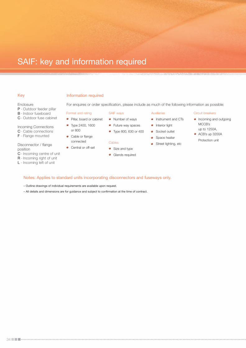
SAIF: key and information required
Key
EnclosureP - Outdoor feeder pillarB - Indoor fuseboardC - Outdoor fuse cabinet
Incoming ConnectionsC - Cable connectionsF - Flange mounted
Disconnector / flangepositionC - Incoming centre of unitR - Incoming right of unitL - Incoming left of unit
Notes: Applies to standard units incorporating disconnectors and fuseways only.
– Outline drawings of individual requirements are available upon request.
– All details and dimensions are for guidance and subject to confirmation at the time of contract.
Format and rating
Pillar, board or cabinet
Type 2400, 1600
or 800
Cable or flange
connected
Central or off-set
SAIF ways
Number of ways
Future way spaces
Type 800, 630 or 400
Cables
Size and type
Glands required
Auxiliaries
Instrument and CTs
Interior light
Socket outlet
Space heater
Street lighting, etc
Circuit breakers
Incoming and outgoing
MCCB’s
up to 1250A,
ACB’s up 3200A
Protection unit
Information required
For enquires or order specification, please include as much of the following information as possible:
...................................................................................................................................................................34

...................................................................................................................................................................

Enclosed switch disconnectors
Merlin Gerin is a world leader in the manufacture and supply of high, medium and low voltage products for the distribution, protection, control and management of electrical systems and is focused on the needs of both thecommercial and industrial sectors. The newly launched VDINetwork Solutions offer provides flexible, configurable ethernet systems for all communication needs.
Square D is a total quality organisation and its business is to put electricity to work productively and effectively, protecting people, buildings and equipment. Its low voltageelectrical distribution equipment, systems and services areused extensively in residential and commercial applications.
Telemecanique is a UK market leader and world expert inautomation and control. It provides complete solutions, withits range of components, Modicon range of high technologyprogrammable controllers (PLCs), multiple fieldbus and ethernet communication networks, HMI, motion control systems, variable speed drives and communications software. In addition, it offers power distribution through prefabricated busbar trunking.
Schneider Electric’s local supportSchneider Electric is committed to supporting its customers at every stage of a project. Our 180 sales engineers, the largestdedicated sales force in the UK electrical industry, operate from 4 customer support centres.
Our sales engineers are skilled at assessing individual requirements and combined with the expert support of our product specialists, will develop the most effective and economical answer taking relevant regulations and standards fully into account.
To access the expertise of the Schneider Electric group, please call 0870 608 8 608. Each customer support centre includesfacilities for demonstrations and training, and presentation rooms fully equipped with audio visual and video, providing excellent meeting facilities.
www.schneider-electric.co.uk
NOV 2007MGLV6120
Industrial systems and solutions showroomSchneider Electric Ltd, University of Warwick Science Park, Sir William Lyons Road, Coventry CV4 7EZ
Building systems and solutions showroomSchneider Electric Ltd, Stafford Park 5, Telford, Shropshire TF3 3BL
Energy and Infrastructure systems and solutions showroomSchneider Electric Ltd, 123 Jack Lane, Hunslet, Leeds LS10 1BS
Product showrooms
Fax 0870 608 8 6060870 608 8 608Nationwide support on one number - call the Customer Information Centre on
ScotlandSchneider Electric LtdUnit 18 Claremont Centre112a Cornwall Street SouthKinning ParkGlasgow G41 1AA
South WestSchneider Electric LtdPO Box 41Langley RoadChippenhamWiltshire SN15 1JJ
North WestSchneider Electric LtdFirst Floor Market HouseChurch StreetWilmslowCheshire SK9 1AY
Local customer support centres
member of
.co.uk