MG3700A Vector Signal Generator MX370x series …The MG3700A Vector Signal Generator features a...
32
Product Brochure MX3701xxA IQproducer MX370x series software MG3700A Vector Signal Generator
Transcript of MG3700A Vector Signal Generator MX370x series …The MG3700A Vector Signal Generator features a...
Product Brochure
MX3701xxA IQproducer
MX370x series software
MG3700A Vector Signal Generator
EQ_MX3701XIQpro_E700 12/13/06 4:05 PM Page 1

The MG3700A Vector Signal Generator features a 160-MHz high-speed ARB baseband generator, broadband vector modulation, and large-capacity ARB memory to support digital modulation signals used by most communication systems. Its excellent cost performance offers the ideal solution for generating signals used bythe new and growing field of wireless broadband technology, as well as for mobile telecommunications systemsand wireless LANs.Because the MG3700 has a built-in ARB generator, signals are output easily just by selecting the waveform pattern matching the required communication system.The following four categories of waveform patterns are supported:
• Standard waveform patterns• Waveform patterns generated by optional MX3700xxA Waveform Pattern software• Waveform patterns generated by optional MX3701xxA IQproducer software• Waveform patterns converted from data generated by common signal-generation software
Each category contains multiple waveform pattern files each with preset parameters for each system.These default waveform patterns are saved on the MG3700A hard disk for easy access, but other waveform patterns are supported using the IQproducer waveform generation software.Parameters for the waveform for the target communication system are set using a GUI to a generate a waveform pattern file for the MG3700A. After the generated waveform pattern is downloaded to the MG3700A viaLAN or CompactFlash (CF) card, the MG3700A outputs the signal just by choosing the waveform pattern file.In addition, a user-generated custom IQ sample file in ASCII format created by common EDA (Electronic DesignAutomation) software such as MATLAB, can be converted into a custom waveform pattern file for the MG3700A.
2
MX370x Series Software
Selection guide
MATLAB is a registered trademark of The Math works, Inc.CDMA2000® is a registered trademark of the Telecommunications Industry Association (TIA-USA).∗ 1: Read the MX3700xxA Waveform Pattern series catalog.∗ 2: Bluetooth and related logomarks are owned by Bluetooth SIG, Inc. and are used by Anritsu Corporation under license.
Other trademarks, etc., are the property of their respective owners.
Communication system
Mul
ti-ca
rrie
r
AR
IB S
TD
-T61
/T79
/T86
RC
R S
TD
-39
TD
-SC
DM
A
GP
S
Blu
etoo
th®
∗ 2
Mob
ile W
iMA
X(I
EE
E80
2.16
e)
WLA
NIE
EE
802.
11a/
b/g
Dig
ital B
road
cast
(DV
B-T
/H)
Dig
ital B
road
cast
(BS
/CS
/CA
TV
/ISD
B-T
)
ET
C/D
SR
C
PD
C
PH
S
Enh
ance
d-P
HS
GS
M/E
DG
E
CD
MA
2000
®
CD
MA
2000
®1x
EV
-DO
HS
DP
A/H
SU
PA
HS
DP
A(T
est
Mod
el5)
W-C
DM
A
AW
GN
Page
Preinstalled
MX370001ATD-SCDMA
MX370002APublic Radio SystemStandard accessories AWGN
Standard accessories W-CDMA
MX370101AHSDPA
MX370102ATDMA
MX370103ACDMA2000 1xEV-DO
MX370104AMulti-carrier
MX370105AMobile WiMAX
MX370106ADVB-T/H
Wav
efor
m
patte
rn∗ 1
IQpr
oduc
er
4 6 8 15 12 12 12 12 26 21 12 12 19
Multi-carrier IQproducer is software that generates the multi career signal based on waveform pattern of varioustelecommunications systems.
EQ_MX3701XIQpro_E700 12/13/06 4:05 PM Page 2

3
Memory A
Memory B
HDD 40 GB
Output signal
Waveform patterns areselected from both ARBmemories A and B foroutput by one of thefollowing methods:
A only B only A + B
Standard accessories W-CDMA IQproducer AWGN IQproducerMX370101A HSDPA/HSUPA IQproducerMX370102A TDMA IQproducerMX370103A CDMA2000 1xEV-DO IQproducer MX370104A Multi-carrier IQproducerMX370105A Mobile WiMAX IQproducerMX370106A DVB-T/H IQproducer
IQproducer is PC application software used for generating waveform pattern filesfor the MG3700A by editing parameters for the modulation signals matchingthe target communication system.The generated waveform pattern files are saved in the MG3700A once and thenloaded to the waveform memory for use.
Optional waveform patterns are saved in the MG3700A once and then loaded to waveform memory for use.
MX370001A TD-SCDMAMX370002A Public Radio System
From IQproducer
From IQproducer
TD-SCDMA
Public radio system
AWGN
WLAN
Digital Broadcast
PHS
PDC
CDMA2000 1xEV-DO
CDMA2000
GSM/EDGE
W-CDMA
ARB memory 1 GB = 256 M samples (Standard) 2 GB = 512 M samples (Option)
MG3700A Vector Signal Generator
Standard waveform patterns saved on MG3700A hard disk
Download
Install
Download
Waveform patterns transferred fromHDD to ARB memory
EQ_MX3701XIQpro_E700 12/13/06 4:05 PM Page 5

4
AWGN IQproducerStandard accessory
AWGN IQproducer
This GUI-based application software is used to generate AWGN(Additive White Gaussian Noise) waveform pattern files optimized for each communication system for the DynamicRange Test, etc.The AWGN waveform pattern file is created by setting the samebandwidth and sampling rate as the combined waveform pattern(Wanted Signal) and a multiplier of the Wanted Signal.Specifying the combined waveform pattern (Wanted Signal)from the waveform pattern for the desired communicationmethod automatically sets the Wanted Signal bandwidth andsampling rate.The resultant AWGN waveform pattern and an existing waveform pattern can be combined, which is useful for measur-ing base-station dynamic range.
<Configurable Parameters>(With Specified Wanted Signal)
AWGN BW/Wanted Signal BW ratio(With Unspecified Wanted Signal)
Wanted Signal BW,AWGN BW, Sampling Rate
Main Parameter Settings(1) Wanted Signal BW: Wanted Signal bandwidth
Setting range: 0.0010 to 120.0000 MHz
(2) AWGN BW (B)/Wanted Signal BW (A):Magnification of AWGN to Wanted SignalSetting range: 1.0, 1.5, 2.0, 2.5
(3) Sampling Rate:Setting range: 0.0200 to 160.0000 MHzBecomes same value as Wanted Signal
(4) AWGN BW (B): Bandwidth of AWGNCalculated automatically from (1) and (2) with following limitation:Limit range: 0.001 to 20.000 MHz and Sampling rate/2 max.,20.001 to 120.000 MHz and Sampling rate max.
• IQproducer Main Screen
• AWGN IQproducer Setting Screen
EQ_MX3701XIQpro_E700 12/13/06 4:05 PM Page 6

5
AWGN IQproducerStandard accessory
Because the MG3700A internal ARB memory can be partitionedin two, the Wanted Signal can be saved in one partition whilethe Interference Signal is saved in the other (Fig. A).The two signals are output after combination in the MG3700Ainternal baseband block. The signal levels can be setindependently and the C/N value can be set too (Fig. B).In addition, the frequency offset of the Wanted Signal andInterference Signal can be set on-screen (Fig. C).The built-in Combination function automatically sets the following (Fig. D):
• Set Wanted Signal in Memory A.
• Set Interference Signal in Memory B.
• Set level of Wanted Signal.
• Set Level of Interference Signal.
• Set offset frequency of Wanted Signal and Interfering Signal.
The Combination function supports full auto-setting of parametersfor the Wanted Signal, Interference Signal, Level Ratio, andFrequency Offset simply by selecting the Combination File.Each parameter can also be set separately on-screen afterauto-setting, if necessary.Combination files for W-CDMA_BS, PDC, and PHS are pre-installed on the MG3700A hard disk and the customer cancustomize these files as necessary using the bundled freetools.
WLAN Wanted Signal + AWGN
WLAN Wanted Signal + AWGN Spectrum
Automatic setting by Combination file
Memory A:Wanted signal
Memory B: AWGN/
Modulation Interference signal
Easy level ratio setting
• Wanted signal level
• Wanted signal band level
• Interference signal level
• C/N
D
A
B
Frequency offset setting
C
Memory A:Wanted signal
Memory B:AWGN
EQ_MX3701XIQpro_E700 12/13/06 4:05 PM Page 9

6
W-CDMA IQproducerStandard accessory
W-CDMA IQproducer
This GUI-based PC application software is used to createwaveform patterns for measuring W-CDMA signal parameters,such as reception sensitivity. The created waveform pattern fileis downloaded to the MG3700A and the W-CDMA basebandsignal and RF signal are output using the built-in arbitrarywaveform generation function.Changing the waveform pattern Scrambling code number andChannelization code number supports creation of waveformpatterns with parameters required for evaluating W-CDMAterminals.The MX370101A HSDPA IQproducer software (sold separately)can set all W-CDMA IQproducer parameters as well as otherparameters. (For details, see the description of MX370101AHSDPA IQproducer.)
CPU Pentium III, 1 GHz or faster
Memory ≥512 Mbytes
HDD ≥5 Gbytes
Display 1024 x 768 pixels min.
OS Windows® 2000 Professional, Windows® XP
• IQproducer™ Operating Environment
• Downlink SettingsDownlink sets parameters including Scrambling code,CPICH/P-CCPCH/PICH/DPCH power, Channelization code,DPCH_PhyCH TFCI and Timing Offset, and DPCH_TrCH Datato create the waveform pattern. (For details, see the DownlinkParameter Setting Range table described later.)Additionally, the Downlink Easy Setup function supports theReference Measurement Channel (RMC) items specified by3GPP TS25.101 and TS25.104. Parameter setting is easy justby selecting the items to create the waveform pattern.
[Easy Setup Items]RMC12.2 Kbps (RX test)RMC12.2 Kbps (Performance test)RMC64 Kbps (Performance test)RMC144 Kbps (Performance test)RMC384 Kbps (Performance test)
• Uplink SettingsUplink sets parameters including Scrambling code, UL-DPCCH/UL-DPDCH power, DPCH_PhyCH TFCI and Timing Offset, andDPCH_TrCH Data to create the waveform pattern. (For details,see the Uplink Parameter Setting Range table described later.)
LAN or Compact Flash
PCMG3700A Vector Signal Generator
(1) IQproducer
installed in PC
(2) Waveform data
created using
IQproducer
(3) Waveform data
transferred to
MG3700A
(4) Waveform data of
output signal
selected
Windows/Windows2000/WindowsXP are registered trademarks ofMicrosoft Corporation in the USA and other countries.
EQ_MX3701XIQpro_E700 12/13/06 4:06 PM Page 10

7
MX370101A HSDPA IQproducer
Display Setting rangeScrambling Code 0 to 8191
CPICH ON/OFF ON or OFFPower –40.00 to 0.00 dB, Resolution 0.01 dBON/OFF ON or OFF
P-CCPCH Power –40.00 to 0.00 dB, Resolution 0.01 dBP-SCH & S-SCH Power –40.00 to 0.00 dB, Resolution 0.01 dBON/OFF ON or OFF
PICH Power –40.00 to 0.00 dB, Resolution 0.01 dBChannelization Code 0 to 255ON/OFF ON or OFFPower –40.00 to 0.00 dB, Resolution 0.01 dB
0 to SF –1The spreading factor (SF) varies with the [Data] setting as follows:RMC 12.2 Kbps = 128
Channelization Code RMC 64 Kbps = 32RMC 144 Kbps = 16RMC 384 Kbps = 8AMR1/AMR2/AMR3 = 128ISDN = 32384 Kbps Packet = 8
Data RMC12.2 Kbps/RMC 64 Kbps/RMC 144 Kbps/RMC 384 Kbps/AMR1/AMR2/AMR3/ISDN/384 Kbps Packet
OCNS ON/OFF ON or OFFType 16 Codes
P-CCPCH Edit SFN Cycle Short or 4096TFCI 0 to 1023DPCH Edit (Phy CH)Timing Offset 0 to 149
DPCH Edit (TrCH Edit) Data PN9/PN9fix/PN15fix/16bitRepeat
• Downlink Parameter Setting Range
Optional
DPCH
Display Setting rangeScrambling Code 0 to 16777215
Power –40.00 to 0 dBUL-DPCCH, UL-DPDCH
DataRMC 12.2 Kbps/RMC 64 Kbps/RMC 144 Kbps/RMC 384 Kbps/AMR1/AMR2/AMR3/ISDN/64 Kbps Packet
DPCH Edit (Phy CH)TFCI 0 to 1023Timing Offset 0 to 149
DPCH Edit (TrCH Edit) Data PN9/PN9fix/PN15fix/16bitRepeatBeta c 0 to 15Channel GainBeta d 0 to 15
• Uplink Parameter Setting Range
• Downlink Main screen • Uplink Main screen
EQ_MX3701XIQpro_E700 12/13/06 4:06 PM Page 13

8
MX370101A HSDPA/HSUPA IQproducerOptional
HSDPA IQproducer
This optional GUI-based PC application software is used to setparameters and generate waveform patterns for 3GPP HSDPA(Uplink/Downlink) systems.The generated waveform pattern files are downloaded to theMG3700A and used to output HSDPA modulation basebandsignals and RF signals.In addition, HS-PDSCH and HS-DPCCH parameters specifiedin TS25.212 can be set. Signals can be generated in variousstates easily by changing the transmission process.And the Downlink Easy Setup function supports typical itemsand parameters, so settings can be executed just by selectingitems/parameters.
CPU Pentium III, 1 GHz or faster
Memory ≥512 Mbytes
HDD ≥5 Gbytes
Display 1024 x 768 pixels min.
OS Windows® 2000 Professional, Windows® XP
• IQproducer™ Operating Environment
• Downlink SettingsVarious downlink parameters can be set. (For details, see theDownlink Parameter Setting table described later.)The Downlink Easy Setup function supports the HSDPA FixedReference Channel (FRC) items specified in 3GPP TS25.101,and the Reference Measurement Channel (RMC) items specified in 3GPP TS25.101 and TS25.104. Parameters are setand waveform patterns are generated just by selecting items.
[Easy Setup Items]FRC: H-Set1 (QPSK), H-Set1 (16QAM), H-Set2 (QPSK),
H-Set2 (16QAM), H-Set3 (QPSK), H-Set3 (16QAM), H-Set4, H-Set5
RMC: RMC12.2 Kbps (RX test)RMC12.2 Kbps (Performance test)RMC64 Kbps (Performance test)RMC144 Kbps (Performance test)RMC384 Kbps (Performance test)
• Uplink Settings:Uplink sets parameters for UL-DPCCH/UL-DPDCH and HS-DPCCH channels and generates waveform patterns.(For details, see the Uplink Parameter Setting Range tabledescribed later).
HS-DPCCH (ACK, NACK, CQI)UL-DPCCHUL-DPDCHE-DPCCHE-DPDCH (s)
LAN or Compact Flash
PC
MX370101A
MG3700A Vector Signal Generator
(1) IQproducer
installed in PC
(2) Waveform data
generated using
IQproducer
(3) Waveform data
transfered to
MG3700A
(4) Waveform data of
output signal
selected
• Parameter save/recall:The numeric values and settings for each item can be saved in a parameter file. Input the name in the [File name] field and click the[Save] button to save the parameter file. Recall a saved parameter file by selecting it in the file list and clicking the [Open] button.
EQ_MX3701XIQpro_E700 12/13/06 4:06 PM Page 14

MX370101A HSDPA/HSUPA IQproducer
9
Display Setting range
Scrambling Code 0 to 8191
CPICH ON/OFF ON or OFF
Power –40.00 to 0.00 dB, Resolution 0.01 dB
P-CCPCH ON/OFF ON or OFF
Power –40.00 to 0.00 dB, Resolution 0.01 dB
ON/OFF ON or OFF
PICH Power –40.00 to 0.00 dB, Resolution 0.01 dB
Channelization Code 0 to 255
ON/OFF ON or OFF
Power –40.00 to 0.00 dB, Resolution 0.01 dB
0 to SF –1
The spreading factor (SF) varies with the [Data]
setting as follows:
RMC 12.2 Kbps = 128
DPCH Channelization Code RMC 64 Kbps = 32
RMC 144 Kbps = 16
RMC 384 Kbps = 8
AMR1/AMR2/AMR3 = 128
ISDN = 32
384 Kbps Packet = 8
Data RMC12.2 Kbps/RMC 64 Kbps/RMC 144 Kbps/RMC 384 Kbps/AMR1/AMR2/
AMR3/ISDN/384 Kbps Packet/User Edit TrCH
OCNS ON/OFF ON or OFF
Type 16 Codes or 6 Codes
ON/OFF ON or OFF
HS-SCCH1/2/3/4 Power –40.00 to 0.00 dB
Channelization Code 0 to 127
Data PN9/PN9fix/PN15fix/16bitRepeat/Coded
ON/OFF ON or OFF
Power –40.00 to 0.00 dBHS-PDSCH1/2/3/4 Channelization Code 0 to 127
DataPN9/PN9fix/PN15fix/16bitRepeat/HS-DSCH ([PN9] can be set only when all
four HSDPA channels are set to [OFF].)
P-CCPCH Edit SFN Cycle Short or 4096
DPCH Data PN9/PN9fix/PN15fix/16bitRepeat/TrCH
TFCI 0 to 1023
Spreading Factor 4, 8, 16, 32, 64, 128, 256, 512
BER 0.0 to 100.0% DPCH Edit (Phy CH)
Slot Format #0 to #16
Timing Offset 0 to 149
TPC Edit0000 0000 0000 0000 0000 0000 0000 0000 0000 0000 0000 0000 0000 0000 0000 to
1111 1111 1111 1111 1111 1111 1111 1111 1111 1111 1111 1111 1111 1111 1111
• Downlink Parameter Setting Range
Optional
EQ_MX3701XIQpro_E700 12/13/06 4:06 PM Page 17

MX370101A HSDPA/HSUPA IQproducerOptional
10
Display Setting range
TrCH Number 1 to 8
DTX Fix/Flex
Data PN9/PN9fix/PN15fix/16bitRepeat
TTI 10, 20, 40, 80 ms
Max. TrBk Size 0 to 5000
TrBk Size 0 to 5000
DPCH Edit (TrCH Edit) Max TrBk Set No. 0 to 64
TrBk Set No. 0 to 64
CRC 0, 8, 12, 16, 24 bit
Coder CC1/2, CC1/3, TC
RM attribute 1 to 256
BER 0.0% to 100.0%
BLER 0% to 100%
Channelization Code Offset 1 to (16 - Number of Physical Channel Code)
Number of Physical Channel Code 1 to (16 - Channelization Code Offset)
Modulation QPSK or 16QAM
HSDPA transport channelTransport Block Size Information 0 to 63
(HS-SCCH, HS-PDSCHRV Information 0 to 7
UE Identity 0 to 65535parameters)
CRC Error Insertion Correct or Fail (CRC error of all)
Number of HARQ Processes 0 to 8
Virtual IR Buffer Size 800 to 304000 (Resolution: 800)
Payload Data PN9/PN9fix/PN15fix/16bitRepeat
HARQ Process Cycle 1 to 16 (Note ranges from 1 to 6 when PN9 set for Payload
Data)
Transmitting Pattern Edit Inter-TTI Distance 1 to 8
TTI Start Offset 0 to 7
Process Setting File Used or Not used
• Downlink Main screen • Uplink Main screen
EQ_MX3701XIQpro_E700 12/13/06 4:06 PM Page 18

Display Setting rangeScrambling Code 0 to 16777215
Channel ON/OFF ON or OFFPower –40.00 to 0 dB
UL-DPCCH, UL-DPDCH Nmax-dpdch 0, 1
Data RMC 12.2 Kbps/RMC 64 Kbps/RMC 144 Kbps/RMC 384 Kbps/AMR1/AMR2/ AMR3/ISDN/64 Kbps Packet/User Edit TrCH
ON/OFF ON or OFFTiming Offset 0 to 149ACK Power –40.00 to 0 dB
HS-DPCCHNACK Power –40.00 to 0 dBCQI Power –40.00 to 0 dBACK Pattern ACK_only, NACK_only, alt_ACK_NACK_DTXCQI value 0 to 30Pattern Setting File Used or Not usedE-DPCCH ON/OFF ON or OFFE-DPDCH ON/OFF ON or OFF
E-DPCCH, E-DPDCH E-DPCCH Power –40.00 to 0 dBE-DPDCH Power –40.00 to 0 dBE-DPDCH (SF2) Power/E-DPDCH (SF4) Power
–10.00 to 10.00 dB
UL-DPDCH Data PN9/PN9fix/PN15fix/16bitRepeat/TrCHTFCI 0 to 1023Spreading Factor 4, 8, 16, 32, 64, 128, 256BER 0.0% to 100.0% (Enabled when [Data] set to [PN9])DPCH Edit (Phy CH)Slot Format #0 to #1 (Only enabled when [UL-DPDCH Data] set to [ TrCH])Timing Offset 0 to 149
TPC Edit 0000 0000 0000 0000 0000 0000 0000 0000 0000 0000 0000 0000 0000 0000 0000 to 1111 1111 1111 1111 1111 1111 1111 1111 1111 1111 1111 1111 1111 1111 1111
TrCH Number 1 to 8Data PN9/PN9fix/PN15fix/16bitRepeatTTI 10, 20, 40, 80 msMax. TrBk Size 0 to 5000TrBk Size 0 to 5000
DPCH Edit (TrCH Edit)Max TrBk Set No. 0 to 64TrBk Set No. 0 to 64CRC 0, 8, 12, 16, 24 bitCoder CC1/2, CC1/3, TCRM attribute 1 to 256BER 0.0% to 100.0% (Only enabled when [Data] set to [PN9])BLER 0% to 100% (Only enabled when [Data] set to [PN9])HARQ Process Setting File Common dialog opens when the check box is checked. HARQ Process Setting
File can be selected. E-DPDCH and E-DPCCH Data PN9, PN9fix, PN15fix, 16bit repeat, CodedE-DPCCH Edit (Phy CH) E-DPDCH Data PN9, PN9fix, PN15fix, 16bit repeat, E-DCH
HS-DSCH Configured Yes, NoE-DPDCH Channel Codes SF256, SF128, SF64, SF32, SF16, SF8, SF4, 2SF4, 2SF2, 2SF2and2SF4E-DCH TTI 2 ms, 10 ms
Information Bit Payload18 to 11484 (at E-DCH TTI = 2 ms)18 to 20000 (at E-DCH TTI = 10 ms)
E-DCH Payload Data PN9, PN9fix, PN15fix, 16bit repeatE-DPDCH and E-TFCI Information 0 to 127E-DPCCH Edit (Tr CH) RSN 0 to 3
Pattern Length Display onlyE-DCH RV Index 0 to 3CRC Error Insertion Correct, Error"Happy" Bit 0, 1
MX370101A HSDPA/HSUPA IQproducer
11
• Uplink Parameter Setting Range
Optional
EQ_MX3701XIQpro_E700 12/13/06 4:08 PM Page 21

12
MX370102A TDMA IQproducerOptional
TDMA IQproducer
This optional GUI-based PC application software is used to setthe parameters and generate waveform patterns for TDMAsystems. The generated waveform pattern files are downloadedto the MG3700A and used to generate TDMA modulation baseband and RF signals.In addition to signals supporting PDC, PHS, ARIB STD-T61/T79/T86, Enhanced-PHS, ETC and DSRC systems, signals forother systems can also be generated.
CPU Pentium III, 1 GHz or faster
Memory ≥512 Mbytes
HDD ≥5 Gbytes
Display 1024 x 768 pixels min.
OS Windows® 2000 Professional, Windows® XP
• IQproducer™ Operating Environment
LAN or Compact Flash
PC
(1) IQproducer
installed in PC
(2) Waveform data
generated using
IQproducer
(3) Waveform data
transfered to
MG3700A
(4) Waveform data of
output signal
selected
MG3700A Vector Signal Generator
MX370102A
• Main Screen • Parameter Setting Items List
Setting Parameter Setting Sheet
Burst Continuous No Format
Modulation
Frame —
Slot —
Field —
Data — —
Filter
Pattern Name
Calculation
EQ_MX3701XIQpro_E700 12/13/06 4:08 PM Page 22

(1st/2nd) Modulation Type Number of Bits in 1st Field Number of Bits in 24th FieldBPSK, DBPSK, PI/2DBPSK, ASK, FSK Integer between 0 and 16 Integer between 1 and 16QPSK, DQPSK, PI/4DQPSK Multiples of 2 between 0 and 32 Multiples of 2 between 2 and 328PSK, D8PSK Multiples of 3 between 0 and 48 Multiples of 3 between 3 and 4816QAM Multiples of 4 between 0 and 64 Multiples of 4 between 4 and 6432QAM Multiples of 5 between 0 and 80 Multiples of 5 between 5 and 8064QAM Multiples of 6 between 0 and 96 Multiples of 6 between 6 and 96256QAM Multiples of 8 between 0 and 128 Multiples of 8 between 8 and 128
Items Display Outline Setting rangeBPSK, DBPSK, PI/2DBPSK, QPSK, DQPSK, PI/4DQPSK, 8PSK∗ ,
Modulation Type D8PSK∗ , 16QAM∗ , 32QAM∗ , 64QAM∗ , 256QAM∗ , ASK, FSK (1st Modulation Type)
1st Modulation Type(∗ Decimal numbers for each symbol point are changed by selecting a user file for IQ mapping.)
Modulation Type2nd Modulation Type
BPSK, DBPSK, PI/2DBPSK, QPSK, DQPSK, PI/4DQPSK, 8PSK, (2nd Modulation Type) D8PSK, 16QAM, 32QAM, 64QAM, 256QAMSymbol Rate Symbol Rate 1 ksps to 80 Msps (can be set in the 1 sps units)Over Sampling Over Sampling Rate 2, 3, 4, 8, 16, 32
20 kHz to 160 MHz (The value of symbol rate x oversampling
Sampling Rate Sampling Raterate is set automatically. However, when the Manchester codesetting enabled, the value of symbol rate x oversampling rate x 2 is set automatically.)Enable/disable automatic setting in accordance with GSM
GSM GSM Setting (Enabled when 8PSK or FSK set as modulation type) Modulation Index Modulation Index 0.00 to 1.00 (for ASK), 0.20 to 10.00 (for FSK)
The Manchester code is selected when this checkbox is selected, Manchester Code Manchester Code and NRZ is selected when this checkbox is cleared. NRZ is
always selected for modulation types other than ASK.Number of Frames Frame number 1 to 4088, Auto
Frame Number of Slots Slot numbers in one frame 1 to 20per Frame
1, 24 field Guard fieldSet the number of bits listed in the separate table according to Modulation Type.
2, 23 field Ramp fieldSet the number of bits listed in the separate table according to
Slot (Burst) Modulation Type.3 to 22 field Fixed (Fixed data) field Set integer from 0 to 128.3 to 22 field Data (PN9, PN15) field Set integer from 0 to 1024.
4 to 22 fieldCRC (Cyclic Redundancy Check character) field
0, 8, 12, 16, 24, 32
1 to 24 field Fixed (Fixed data) field Set integer from 0 to 128.
Slot (Continuous) 1 to 24 field Data (PN9, PN15) field Set integer from 0 to 1024.
2 to 24 fieldCRC (Cyclic Redundancy Check character) field
0, 8, 12, 16, 24, 32
Fixed Sets hexadecimal fixed data 0 to maximum value of number of bits setField
CRCSets CRC calculation 1 to number of bits in field on left to CRC
(Burst/ field as integer (except Guard and Ramp fields)Continuous) Data Field Selects continuous pattern PN9, PN15, 16-bit Pattern, ALL0, ALL1, UserFile∗∗
Input any hexadecimal number for 16-bit Pattern.Data (No Format) Data Selects continuous pattern PN9, PN15, 16-bit Pattern, ALL0, ALL1, UserFile∗∗
Filter Filter type Root Nyquist, Nyquist, Gaussian, IdealLowpass, NoneRoll Off/BT Roll off rate/BT product 0.10 to 1.00 (When Nyquist/Root Nyquist/Gaussian is set.)
FilterFs/2, Fs/3, Fs/4, Fs/8, Fs/16, Fs/32 (This item is displayed and
Passband Passband of filter can be set only when IdealLowpass is set as the filter type. The setting range varies with the oversampling rate.)
RMSRMS value of waveform pattern data
651 to 4104
Pattern NamePattern Name Waveform pattern file name Within 20 charactersComment Comment Within 38 characters
Calculation Starts waveform pattern data generation after setting parameters.
MX370102A TDMA IQproducer
13
• Guard Field Setting Range
• Parameter Setting Items List
Optional
Modulation
∗∗ When “UserFile” is set, the binary sequences before it is modulated can be read from the text file. Up to 9,600,000 bits can be loaded.
EQ_MX3701XIQpro_E700 12/13/06 4:09 PM Page 25

MX370102A TDMA IQproducer
14
Optional
• Ramp Field Setting Range
(1st/2nd) Modulation Type Number of Bits
BPSK, DBPSK, PI/2DBPSK,
ASK, FSKInteger number between 1 and 16
QPSK, DQPSK, PI/4DQPSK Multiples of 2 between 2 and 32
8PSK, D8PSK Multiples of 3 between 3 and 48
16QAM Multiples of 4 between 4 and 64
32QAM Multiples of 5 between 5 and 80
64QAM Multiples of 6 between 6 and 96
256QAM Multiples of 8 between 8 and 128
• Parameter Save/Recall
• Graph Display:This function displays the generated waveform as a CCDF orFFT graph on the PC screen. It is useful for checking/reviewing waveforms before transfer to the MG3700A.
CCDF (Complimentary Cumulative Distribution Function) GraphUp to 8 types of generated waveform can be read and displayed as CCDF graphs.
CCDF Graph Screen
FFT Graph Screen
FFT (Fast Fourier Transform) GraphUp to 4 types of generated waveform patterns can be read andthe transformed results displayed as FFT graphs.
The numeric values and settings for each item can be saved ina parameter file. Input the name in the [File name] field andclick the [Save] button to save the parameter file. Recall asaved parameter file by selecting it in the file list and clickingthe [Open] button.
EQ_MX3701XIQpro_E700 12/13/06 4:09 PM Page 26

15
MX370103A CDMA2000 1xEV-DO IQproducerOptional
CDMA2000 1xEV-DO IQproducer
This optional GUI-based PC application software is used to setparameters and generate waveform pattern files forCDMA2000 1xEV-DO systems (1xEV-DO forward and 1xEV-DO Reverse).The generated waveform pattern files are downloaded to theMG3700A and used to output CDMA2000 1xEV-DO modulationbaseband signals and RF signals.Forward generates multi-carrier signals for up to nine carriersand Idle and Active mixed signals.Reverse generates multi-user signals with freely adjustablefrequency, phase, level, and delay.
CPU Pentium III, 1 GHz or faster
Memory ≥512 Mbytes
HDD ≥5 Gbytes
Display 1024 x 768 pixels min.
OS Windows® 2000 Professional, Windows® XP
• IQproducer™ Operating Environment
LAN or Compact Flash
PCMG3700A Vector Signal Generator
MX370103A
(1) IQproducer
installed in PC
(2) Waveform data
generated using
IQproducer
(3) Waveform data
transfered to
MG3700A
(4) Waveform data of
output signal
selected
• 1xEV-DO Forward Setting Screen
EQ_MX3701XIQpro_E700 12/13/06 4:09 PM Page 29

Display Setting Range
Spacing Sets frequency interval between carriers with consecutive carrier numbers from 1.20, 1.23, or 1.25 MHz.
Carrier SelectTurns on single carrier used to generate multi-carrier (or single carrier, if only one single carrier turned on with all others turned off) in single carrier generated in Carrier Edit sheet.
Target RMS Range“RMS” indicates waveform pattern RMS value. Set the maximum value to “Max” when adjusting the waveform patternRMS value.
RMS Adjustment Value Sets RMS value of multi- or single-carrier waveform pattern.
RMS AdjustConverts waveform pattern generated by clicking Composition Execute button into waveform pattern with RMS valueclose to value input in RMS Adjustment Value.
Display Setting Range
Frame Selects frame where RPC and RA channels to be edited.
Slot Selects slot where RPC and RA channels to be edited.
RA Bit RA bit of RA channel. Set 0 or 1.
CH Power Channel gain of MAC channel (relative value to pilot channel). Set from –40 to +40 dB.
RPC Bit RPC bit of RPC channel. Set 0 or 1.
ON/OFF Turns each MAC channel on/off.
Sets all channel gains of RPC and RA channels in currently-set slot collectively to ratio expressed as fraction. Normalize
The numerator of the RA channel ratio can be set from 1 to denominator –1. The denominator can be set from 2 to 99.
MX370103A CDMA2000 1xEV-DO IQproducerOptional
16
• 1xEV-DO Forward Setting Range[Carrier Edit Sheet]Set the modulation parameters for single carriers (associated with carrier numbers 1 to 9) constituting the multi-carrier on the CarrierEdit sheet.
Display Setting Range
Wave Data Length Number of frames of generated waveform pattern. Specify up to 4 frames. Specify 3 frames when generating multi-carrier.
Over Sampling Over sampling rate for waveform patterns. Set 4, 8, or 16.
Default All Restores settings of all single carriers to initial values.
Carrier Select single carrier to be edited from 1 to 9.
Carrier Parameters CopySpecify single carrier where settings for currently-set single carrier to be copied (copy destination). Set Carrier 1 to Carrier 9 or All Carrier.
Copies settings of currently-set single carrier (corresponding to carrier number displayed in Carrier) to copy destination Execute
specified by Carrier Parameters Copy. Copied settings include contents of RPC/RA CH Parameter screen.
Set data rate and transmission slot for generated single carrier from following: 38.4 Kbps (16 slots) QPSK, 76.8 Kbps (8 slots) QPSK, 153.6 Kbps (4 slots) QPSK, 307.2 Kbps (2 slots) QPSK, 614.4 Kbps (1 slot) QPSK,
Data Rate307.2 Kbps (4 slots) QPSK, 614.4 Kbps (2 slots) QPSK, 1228.8 Kbps (1 slot) QPSK, 921.6 Kbps (2 slots) 8-PSK, 1843.2 Kbps (1 slot) 8-PSK, 1228.8 Kbps (2 slots) 16QAM, 2457.6 Kbps (1 slot) 16QAM, Idle Slot
1st to 4th Frame Active (1)/Idle (0)
Set traffic channel active/idle for each slot.
Set traffic channel payload data.
TCH DataAll ‘0’: Sets payload data to all 0 s.All ‘1’: Sets payload data to all 1s.PN15: Sets payload data to discontinuous PN15 sequence. PN15 is continuous within a frame.
Offset Index Specify PN Offset Index of generated single carrier from 0 to 511.
TCH1 to TCH4 Specify MAC Index used for scrambling sequence of traffic channel and preamble Walsh cover as integer from 5 to 63.
Initial value of linear feedback shift register used to generate PN15 sequence when TCH Data set to PN15. Reg1 to Reg4 Set hexadecimal number from 0 to 7FFF. The offset can be added to the PN15 sequence of each TCH by changing
this initial value.
Restores settings of single carrier currently set on screen to initial values. (The corresponding carrier number is Carrier Default
displayed in Carrier.) The settings in the Carrier Parameters frame are restored to the initial values of the single carrier.
RPC/RA CH Parameters Opens the RPC/RA CH Parameters screen setting parameters of RPC and RA channels.
Generates waveform patterns for 9 single carriers with current settings. After clicking this button, the entire Carrier Calculate
process on the Carrier Edit sheet is completed when “Complete” is displayed on the Execution and Result screen.
• RPC/RA CH Parameters Sheet
[Multi-carrier Composition Sheet]Generates multi-carrier or single carrier waveform pattern from single carrier waveform patterns generated in Carrier Edit sheet
EQ_MX3701XIQpro_E700 12/13/06 4:09 PM Page 30

17
• 1xEV-DO Reverse Setting Range
Display Description Setting Range
Over Sampling Ratio of waveform pattern sampling rate and chip rate. 4, 8, 16
Carrier On/Off Set carrier On/Off. On when checked. On, Off
Long Code Mask Set I and Q long code masks. MQ set automatically when MI set by user. MI, MQ: 0x0 to 0x3FFFFFFFFFF
Power Set carrier power. –80.000 to 0.000 dB
Frequency Offset Set carrier frequency offset from center frequency setting of MG3700A. –5.000 to 5.000 MHz
DelaySet carrier delay. The delay is the time interval from when a frame trigger is outputfrom the rear panel of the MG3700A to when the first frame of the carrier is output.
0 chip to 32768 chip
Phase Offset Set carrier phase offset. 0.000 to 2.000 pai rad.
DRC CH On/Off Set DRC channel On/Off. "On” when checked. On, Off
DRC CH Gain Set channel gain of DRC channel by value relative to pilot channel. –80.000 to 20.000 dB
DRC Symbol Set DRC channel symbol data in hexadecimal.0000000000000000 toFFFFFFFFFFFFFFFF(HEX)
DRC CoverSymbol Set DRC cover symbol data in octal.0000000000000000 to7777777777777777 (OCT)
ACK CH On/Off Set ACK channel On/Off. “On” when checked. On, Off
ACK CH Gain Set channel gain of ACK channel by value relative to pilot channel. –80.000 to 20.000 dB
ACK CH Bit Set ACK channel bit. A (ACK), N (NACK), X (DTX)
Data CH On/Off Set Data channel On/Off. “On” when checked. On, Off
Data CH Gain Set channel gain of Data channel by value relative to pilot channel. –80.000 to 20.000 dB
Data Rate Set Data channel data rate. 9.6, 19.2, 38.4, 76.8, 153.6 Kbps
DataSet Data channel payload data. The “PN9fix” selection item specifies a discontinuous PN9 code sequence.
PN9fix, All '0', All '1'
Initial LFSRWhen PN9fix set for Data, set initial value of PN9 generation shift register in hexadecimal.
0 to 1FF (HEX)
RRI Symbol Set RRI symbol in binary. 000 to 101 (BIN)
MX370103A CDMA2000 1xEV-DO IQproducerOptional
EQ_MX3701XIQpro_E700 12/13/06 4:09 PM Page 31

MX370103A CDMA2000 1xEV-DO IQproducer
18
Optional
Parameter Save/Recall
The numeric values and settings for each item can be saved ina parameter file. Input the name in the [File name] field andclick the [Save] button to save the parameter file. Recall asaved parameter file by selecting it in the file list and clickingthe [Open] button.
Graph Display
This function displays a generated waveform as a CCDF orFFT graph on the PC screen. It is useful for checking/reviewingwaveforms before transfer to the MG3700A.
CCDF (Complimentary Cumulative Distribution Function) GraphUp to 8 types of generated waveform can be read and displayed as CCDF graphs.
FFT (Fast Fourier Transform) GraphUp to 4 types of generated waveform patterns can be read and the results displayed as FFT graphs.
CCDF Graph Screen FFT Graph Screen
EQ_MX3701XIQpro_E700 12/13/06 4:09 PM Page 28
19
MX370104A Multi-carrier IQproducerOptional
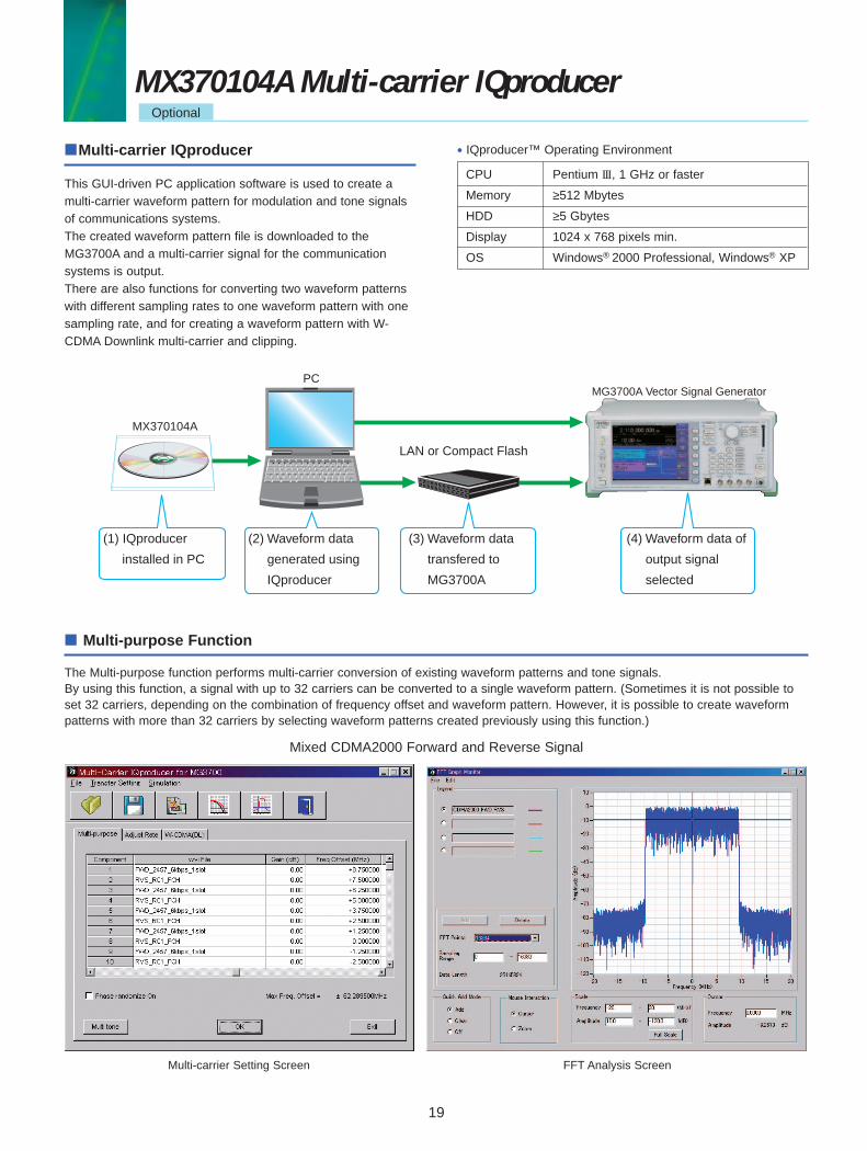
Multi-carrier IQproducer
This GUI-driven PC application software is used to create amulti-carrier waveform pattern for modulation and tone signalsof communications systems.The created waveform pattern file is downloaded to theMG3700A and a multi-carrier signal for the communication systems is output.There are also functions for converting two waveform patternswith different sampling rates to one waveform pattern with onesampling rate, and for creating a waveform pattern with W-CDMA Downlink multi-carrier and clipping.
CPU Pentium III, 1 GHz or faster
Memory ≥512 Mbytes
HDD ≥5 Gbytes
Display 1024 x 768 pixels min.
OS Windows® 2000 Professional, Windows® XP
• IQproducer™ Operating Environment
LAN or Compact Flash
PC
MX370104A
MG3700A Vector Signal Generator
(1) IQproducer
installed in PC
(2) Waveform data
generated using
IQproducer
(3) Waveform data
transfered to
MG3700A
(4) Waveform data of
output signal
selected
Mixed CDMA2000 Forward and Reverse Signal
Multi-carrier Setting Screen FFT Analysis Screen
Multi-purpose Function
The Multi-purpose function performs multi-carrier conversion of existing waveform patterns and tone signals.By using this function, a signal with up to 32 carriers can be converted to a single waveform pattern. (Sometimes it is not possible toset 32 carriers, depending on the combination of frequency offset and waveform pattern. However, it is possible to create waveformpatterns with more than 32 carriers by selecting waveform patterns created previously using this function.)
EQ_MX3701XIQpro_E700 12/13/06 4:09 PM Page 27
20
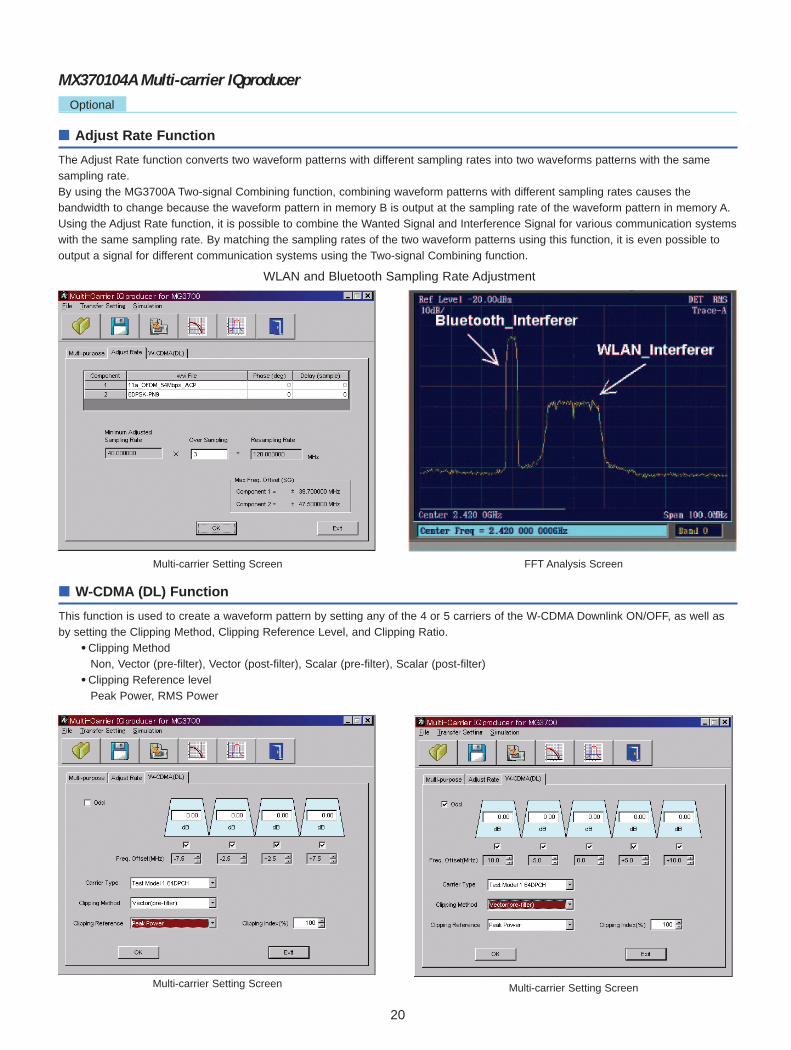
Adjust Rate Function
The Adjust Rate function converts two waveform patterns with different sampling rates into two waveforms patterns with the samesampling rate.By using the MG3700A Two-signal Combining function, combining waveform patterns with different sampling rates causes the bandwidth to change because the waveform pattern in memory B is output at the sampling rate of the waveform pattern in memory A.Using the Adjust Rate function, it is possible to combine the Wanted Signal and Interference Signal for various communication systemswith the same sampling rate. By matching the sampling rates of the two waveform patterns using this function, it is even possible tooutput a signal for different communication systems using the Two-signal Combining function.
Multi-carrier Setting Screen FFT Analysis Screen
Multi-carrier Setting Screen Multi-carrier Setting Screen
WLAN and Bluetooth Sampling Rate Adjustment
W-CDMA (DL) Function
This function is used to create a waveform pattern by setting any of the 4 or 5 carriers of the W-CDMA Downlink ON/OFF, as well asby setting the Clipping Method, Clipping Reference Level, and Clipping Ratio.
• Clipping MethodNon, Vector (pre-filter), Vector (post-filter), Scalar (pre-filter), Scalar (post-filter)
• Clipping Reference levelPeak Power, RMS Power
MX370104A Multi-carrier IQproducerOptional
EQ_MX3701XIQpro_E700 12/13/06 4:09 PM Page 24

21
MX370105A Mobile WiMAX IQproducerOptional
Mobile WiMAX IQproducer
This GUI-driven PC application software is used to setparameters and generate waveform patterns based on theIEEE802.16e-2005 WirelessMAN-OFDMA MAC/PHY standard.Generated waveform pattern files are downloaded to theMG3700A and used to output WirelessMAN OFDMAmodulation baseband signals and RF signals.Some parameters of the DL/UL-MAP and DCD/UCD, etc., MACmanagement messages can be set.The generated waveform pattern can be used for part∗ of theIEEE802.16e tests (8.4.13 Receiver Requirement).∗ Excludes function tests (Handover, etc.) not done using only signal
generator.
CPU Pentium III, 1 GHz or faster
Memory ≥512 Mbytes
HDD ≥5 Gbytes
Display 1024 x 768 pixels min.
OS Windows® 2000 Professional, Windows® XP
• IQproducer™ Operating Environment
LAN or Compact Flash
PCMG3700A Vector Signal Generator
MX370105A
(1) IQproducer
installed in PC
(2) Waveform data
generated using
IQproducer
(3) Waveform data
transfered to
MG3700A
(4) Waveform data of
output signal
selected
Recommended OptionsMG3700A-021 ARB Memory Upgrade 512 M SampleThe IEEE802.16e Receiver Requirement has an item forchecking whether specifications are met by adding anInterference Signal to the Wanted Signal. This check requirestwo signals but by using the Two-signal Combine function, oneMG3700A unit can output both the Wanted and Interferencesignals. In addition, if the memory is increased, severalwaveform patterns for different communication methods can besaved in memory for instant recall when required.
MG3700A-031 High-Speed BER Test FunctionThe IEEE802.16e Receiver Requirement has a BERmeasurement test that uses a Fixed pattern. The optionalMG3700A-031 High-Speed BER test function∗ supports BERmeasurement using a Fixed pattern.∗ The standard BER function does not support Fixed-pattern measurement.
Parameter Save/RecallThe numeric values and settings for each item can be saved ina parameter file. Input the name in the [File name] field andclick the [Save] button to save the parameter file. Recall asaved parameter file by selecting it in the file list and clickingthe [Open] button.
Graph DisplayThis function displays a generated waveform as a CCDF orFFT graph on the PC screen. It is useful for checking/reviewingwaveforms before transfer to the MG3700A.CCDF (Complimentary Cumulative Distribution Function) GraphUp to 8 types of generated waveform can be read and displayedas CCDF graphs.FFT (Fast Fourier Transform) GraphUp to 4 types of generated waveform patterns can be read andthe transformed results displayed as FFT graphs.
EQ_MX3701XIQpro_E700 12/13/06 4:09 PM Page 23
22
MX370105A Mobile WiMAX IQproducerOptional
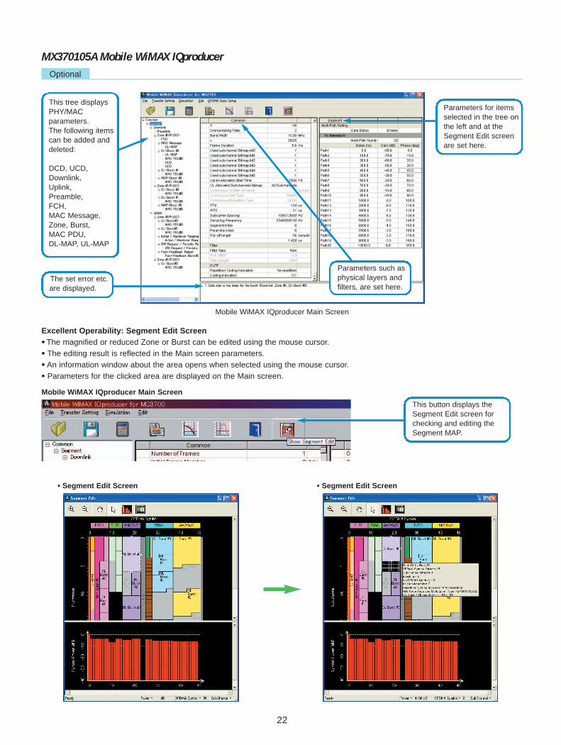
Mobile WiMAX IQproducer Main Screen
Mobile WiMAX IQproducer Main Screen
• Segment Edit Screen • Segment Edit Screen
Excellent Operability: Segment Edit Screen• The magnified or reduced Zone or Burst can be edited using the mouse cursor.
• The editing result is reflected in the Main screen parameters.
• An information window about the area opens when selected using the mouse cursor.
• Parameters for the clicked area are displayed on the Main screen.
This tree displaysPHY/MAC parameters.The following itemscan be added anddeleted:
DCD, UCD,Downlink,Uplink,Preamble,FCH,MAC Message,Zone, Burst,MAC PDU,DL-MAP, UL-MAP
The set error etc.are displayed.
Parameters such asphysical layers andfilters, are set here.
Parameters for itemsselected in the tree onthe left and at theSegment Edit screenare set here.
This button displays theSegment Edit screen forchecking and editing theSegment MAP.
EQ_MX3701XIQpro_E700 12/13/06 4:08 PM Page 20

23
MX370105A Mobile WiMAX IQproducerOptional
Tree Items Setting RangeFrame Duration =Continuous
Common Number of Tx Antennas 1, 2Number of Frames∗ 1 1 to maximum number of Frames saved in MG3700A ARB memory Can not be set.Initial Frame Number 000000 to FFFFFF (hex) Can not be set.FFT size 128, 512, 1024, 2048G (CP Time Ratio) 1/4, 1/8, 1/16, 1/32Oversampling Ratio 2, 4, 8
Bandwidth1.25, 1.50, 1.75, 2.50, 3.00, 3.50, 5.00, 6.00, 7.00, 8.75, 10.00, 12.00, 14.00, 15.00, 17.50, 20.00, 24.00, 28.00 MHz
n (Sampling Factor) 8/7, 28/25Frame Duration 2.0, 2.5, 4.0, 5.0, 8.0, 10.0, 12.5, 20.0 ms, ContinuousUsed Subchannel Bitmap bit0 to bit5∗ 1 1, 0
Uplink Allocation Start Time∗ 1 0 to Frame EndPS Can not be set.Uplink Allocation Subchannels Bitmaps
All Subchannels
Continuous OFDMA 2 to maximum number of OFDMA Symbols saved in MG3700A ARB memory Symbols∗ 1 (2-symbol steps)
Can be set.
Continuous Data Type 16 bit repeat, PN9fix, PN15fix, S_QPSK, S_16QAM, S_64QAM, User File Can be set.Continuous Data Type Repeat Data
0000 to FFFF (hex): When Continuous Data Type = 16 bit repeat Can be set.
Continuous Data Type User File
User File is selected: When Continuous Data Type = User File Can be set.
Continuous Modulation Type QPSK, 16QAM, 64QAM: Can be set when Frame Duration = Continuous Can be set.TTG Display only: Gap interval between Downlink and Uplink displayedRTG Display only: Gap interval between Uplink and Frame End displayedSubcarrier Spacing Display only
Sampling FrequencyDisplay only: Depends on Bandwidth, n (Sampling Factor), and Oversampling
Ratio settingsSegment Index 0, 1, 2 Can not be set.Preamble Index <Table 1> Can not be set.Roll Off Length 0 to 32FilterFilter Type Non, Gaussian, Root Nyquist, Nyquist, IdealRoll-Off/BT 0.1 to 1.0: Cannot be set when Filter Type = Non, Ideal.Filter Length 1 to 1024: Cannot be set when Filter Type = Non, Ideal. DLFPRepetition Coding Indication No repetition, 2, 4, 6 Can not be set.Coding Indication CC, CTC Can not be set.
Segment Multi-Path Setting Enable, DisableMulti-Path Number: 1 to 20
Tx Antenna0, 1 Delay: 0.0 to 10000.0 nsGain: –80.0 to 0.0 dBPhase: 0.0 to 359.9 deg
When Segment Index = 0 When Segment Index = 1 When Segment Index = 20(IDcell=0), 1(IDcell=1), 2(IDcell=2), 32(IDcell=0), 33(IDcell=1), 34(IDcell=2), 64(IDcell=0), 65(IDcell=1), 66(IDcell=2), 3(IDcell=3), 4(IDcell=4), 5(IDcell=5), 35(IDcell=3), 36(IDcell=4), 37(IDcell=5), 67(IDcell=3), 68(IDcell=4), 69(IDcell=5), 6(IDcell=6), 7(IDcell=7), 8(IDcell=8), 38(IDcell=6), 39(IDcell=7), 40(IDcell=8), 70(IDcell=6), 71(IDcell=7), 72(IDcell=8), 9(IDcell=9), 10(IDcell=10), 11(IDcell=11), 41(IDcell=9), 42(Idcell=10), 43(IDcell=11), 73(IDcell=9), 74(IDcell=10), 75(IDcell=11), 12(IDcell=12), 13(IDcell=13), 14(IDcell=14), 44(IDcell=12), 45(IDcell=13), 46(IDcell=14), 76(IDcell=12), 77(IDcell=13), 78(IDcell=14), 15(IDcell=15), 16(IDcell=16), 17(IDcell=17), 47(IDcell=15), 48(IDcell=16), 49(IDcell=17), 79(IDcell=15), 80(IDcell=16), 81(IDcell=17), 18(IDcell=18), 19(IDcell=19), 20(IDcell=20), 50(IDcell=18), 51(IDcell=19), 52(IDcell=20), 82(IDcell=18), 83(IDcell=19), 84(IDcell=20), 21(IDcell=21), 22(IDcell=22), 23(IDcell=23), 53(IDcell=21), 54(IDcell=22), 55(IDcell=23), 85(IDcell=21), 86(IDcell=22), 87(IDcell=23), 24(IDcell=24), 25(IDcell=25), 26(IDcell=26), 56(IDcell=24), 57(IDcell=25), 58(IDcell=26), 88(IDcell=24), 89(IDcell=25), 90(IDcell=26), 27(IDcell=27), 28(IDcell=28), 29(IDcell=29), 59(IDcell=27), 60(IDcell=28), 61(IDcell=29), 91(IDcell=27), 92(IDcell=28), 93(IDcell=29), 30(IDcell=30), 31(IDcell=31), 96(IDcell=0), 62(IDcell=30), 63(IDcell=31), 97(IDcell=1), 94(IDcell=30), 95(IDcell=31), 98(IDcell=2), 99(IDcell=3), 102(IDcell=6), 105(IDcell=9), 100(IDcell=4), 103(IDcell=7), 106(IDcell=10), 101(IDcell=5), 104(IDcell=8), 107(IDcell=11), 108(IDcell=12), 111(IDcell=15) 109(IDcell=13), 112(IDcell=16) 110 (IDcell=14), 113(IDcell=17)
• Parameter Setting Items
∗ 1: Read the product introduction materials for details of parameter settings.
Table 1: Preamble Index Setting Range
EQ_MX3701XIQpro_E700 12/15/06 3:59 PM Page 19

24
Tree Items Setting RangeDownlink Data Status Enable, DisablePreamble Data Status Enable, Disable
IDcell Display only: Depends on Preamble Index settingsZone 0 to 7 Data Status Enable, Disable
Permutation PUSC, PUSC (all SC), FUSC, AMC (6 x 1), AMC (3 x 2), AMC (2 x 3), AMC (1 x 6)STC/MIMO No transmit diversity, 2 Antenna MatrixA (STTD), 2 Antenna MatrixB vertical encoding
OFDMA Symbol Offset <Zone#0> 0 (Without Preamble), 1 (With Preamble)<Zone#1 to 7> 0 to 255 symbol (Without Preamble), 1 to 255 symbol (With Preamble)1 to 255 symbol [when FUSC and AMC (6 x 1)], 2 to 254 symbol [when PUSC, PUSC (all SC) and No. OFDMA Symbols AMC (3 x 2)], 3 to 255 symbol [when AMC (2 x 3)], 6 to 252 symbol [when AMC (1 x 6)]
DL-PermBase 0 to 31 (Cannot be set at Zone#0)DL-Burst Number 1 to 16PRBS_ID 0 to 3 (Cannot be set at Zone#0)
FCH Data Status Enable, DisableFCH Type 16 bit repeat, PN9fix, PN15fix, DLFP, User FileFCH Type Repeat Data 0000 to FFFF (hex): Can be set when FCH Type = 16 bit repeatFCH Type User File User File selected: Can be set when FCH Type = User FileUsed Subchannel Bitmap bit0 to 5 Display only: Set at Common.Repetition Coding Indication Display only: Set at Common.Coding Indication Display only: Set at Common.DL-MAP Length Display only: Set at DL-MAP.
MAC Massage Data Status Enable, DisableDL-MAP Data Status Enable, Disable
DL-MAP Type∗ 1 16 bit repeat, PN9fix, PN15fix, S_QPSK, S_16QAM, S_64QAM, DL-MAP, Compressed DL-MAP, User FileDL-MAP Type Repeat Data 0000 to FFFF (hex): Can be set when DL-MAP Type = 16-bit repeatDL-MAP Type User File User File selected: Can be set when DL-MAP Type = User FileDL-MAP Length∗ 1 0 to 255 slotDCD Count 0 to 255: Can be set when DL-MAP Type = DL-MAP or Compressed DL-MAP
Base Station ID 0000 0000 0000 to FFFF FFFF FFFF (hex): Can be set when DL-MAP Type = DL-MAP or Compressed DL-MAP
DL-MAP PHY Synchronization FieldFrame Duration Display only: Set at Common.Initial Frame Number Display only: Set at Common.Zone # DL-MAP IE #DIUC (Downlink Interval Usage Code) 0 to 12OFDMA Symbol Offset Display only: Set at DL-Burst.OFDMA Subchannel Offset Display only: Set at DL-Burst.Boosting Display only: Set at DL-Burst. No. OFDMA Symbol Display only: Set at DL-Burst. No. Subchannels Display only: Set at DL-Burst. Repetition Coding Indication Display only: Set at DL-Burst.Zone # STC/Zone switch IEOFDMA Symbol Offset Display only: Set at DL-Zone.Permutation Display only: Set at DL-Zone.DL Use All SC Indicator Display onlyDL-PermBase Display only: Set at DL-Zone.
DL-Burst 0 to 15 Data Status Enable, DisableOFDMA Symbol Offset∗ 1 0 to 255OFDMA Subchannel Offset 0 to 63 [without AMC (2 x 3) and AMC (1 x 6)], 0 to 255 [when AMC (2 x 3) and AMC (1 x 6)]Boosting –12, –9, –6, –3, 0, +3, +6, +9 dBNo. OFDMA Symbols 1 to 127 symbolNo. Subchannels 1 to 63Repetition Coding Indication∗ 1 No repetition, 2, 4, 6
QPSK (CC) 1/2, QPSK (CC) 3/4, 16QAM (CC) 1/2, 16QAM (CC) 3/4, 64QAM (CC) 1/2, 64QAM (CC) FEC Code Type and 2/3, 64QAM (CC) 3/4, QPSK (CTC) 1/2, QPSK (CTC) 3/4, 16QAM (CTC) 1/2, 16QAM (CTC) 3/4, Modulation Type 64QAM (CTC) 1/2, 64QAM (CTC) 2/3, 64QAM (CTC) 3/4, 64QAM (CTC) 5/6, QPSK (No Ch Coding),
16QAM (No Ch Coding) , 64QAM (No Ch Coding) DL-Burst Data Type 16 bit repeat, PN9fix, PN15fix, S_QPSK, S_16QAM, S_64QAM, MAC PDU, User FileDL-Burst Data Type Repeat Data 0000 to FFFF (hex): Can be set when DL-Burst Data Type = 16-bit repeatDL-Burst Data Type User File User File selected: Can be set when DL-Burst Data Type = User FileMAC PDU Number 0 to 32
UL-MAP Data Status Enable, DisableUL-MAP Type 16 bit repeat, PN9fix, PN15fix, S_QPSK, S_16QAM, S_64QAM, UL-MAP, Compressed UL-MAP, User FileUL-MAP Type Repeat Data 0000 to FFFF (hex): Can be set when UL-MAP Type = 16 bit repeat.UL-MAP Type User File User File selected: Can be set when UL-MAP Type = User File.UL-MAP Length∗ 1 0 to 2037 bytesUCD Count 0 to 255: Can be set when UL-MAP Type = UL-MAP or Compressed UL-MAPUplink Allocation Start Time Display only: Set at Common.
• Downlink [PHY/MAC] Parameter Setting Range
MX370105A Mobile WiMAX IQproducerOptional
EQ_MX3701XIQpro_E700 12/13/06 4:06 PM Page 16

Tree Items Setting RangeUL-MAP Zone# UL-MAP IE #
CID 0 to 65535UIUC (Uplink Interval Usage Code) 1 to 10UL-Burst Duration Display only: Set at UL-Burst.Repetition Coding Indication Display only: Set at UL-Burst.
MAC PDU Data Status Enable, Disable0 to 31 MAC PDU Length Display only
0 to 2041 byte (when CI = No CRC), 0 to 2037 byte (when CI = With CRC), Payload Data Length 0 to 2047 byte (when CI = Without Header & CRC)CID (Connection Identifier) 0 to 65535CI With CRC, No CRC, Without Header & CRCPayload Type 16 bit repeat, PN9fix, PN15fix, S_QPSK, S_16QAM, S_64QAM, User FilePayload Type Repeat Data 0000 to FFFF: Can be set when Payload Type = 16 bit repeat.Payload Type User File User File selected: Can be set when Payload Type = User File.
DCD Data Status Enable, DisableDCD Length∗ 1 Display only Configuration Change Count 0 to 255TLV encoded information for 16 bit repeat, PN9fix, PN15fix, S_QPSK, S_16QAM, S_64QAM, Overall Type User File (Discontinuous between Frames)TLV encoded information for 0000 to FFFF (hex): Overall Type Repeat Data Can be set when TLV encoded information for overall Type = 16-bit repeatTLV encoded information for User File selected: Overall Type User File Can be set when TLV encoded information for overall Type = User FileTLV encoded information for Overall Length 0 to 2037 bytesZone # DL-Burst Profile DL-Burst Profile Length Display only DIUC 0 to 12
TLV Encoded Information Type 16 bit repeat, PN9fix, PN15fix, S_QPSK, S_16QAM, S_64QAM, User File (Discontinuous between Frames)
TLV Encoded Information Type Repeat Data 0000 to FFFF (hex): Can be set when TLV encoded information Type = 16-bit repeat
TLV Encoded Information Type User File User File selected: Can be set when TLV encoded information Type = User FileTLV Encoded Information Length 0 to 254 bytes
UCD Data Status Enable, DisableUCD Length∗ 1 Display only Configuration Change Count 0 to 255Ranging Backoff Start 0 to 255Ranging Backoff End 0 to 255Request Backoff Start 0 to 255Request Backoff End 0 to 255TLV Encoded Information for 16 bit repeat, PN9fix, PN15fix, S_QPSK, S_16QAM, S_64QAM, Overall Type User File (Discontinuous between Frames)TLV Encoded Information for 0000 to FFFF (hex): Overall Type Repeat Data Can be set when TLV encoded information for overall Type = 16-bit repeatTLV Encoded Information for User File selected: Overall Type User File Can be set when TLV encoded information for overall Type = User FileTLV Encoded Information for Overall Length∗ 1 0 to 2037 bytes
Zone # UL-Burst Profile #UL-Burst Profile Length Display only UIUC 1 to 10
TLV Encoded Information Type 16 bit repeat, PN9fix, PN15fix, S_QPSK, S_16QAM, S_64QAM, User File (Discontinuous between Frames)
TLV Encoded Information Type Repeat Data 0000 to FFFF: Can be set when TLV encoded information Type = 16-bit repeat
TLV Encoded Information Type User File User File selected: Can be set when TLV encoded information Type = User FileTLV Encoded Information Length 0 to 254 bytes
MAP-Burst Data Status Enable, DisableOFDMA Symbol Offset 0 to 255OFDMA Subchannel Offset 0 to Number of Subchannel in ZoneLength 1 to 255 slotRepetition Coding Indication No Repetition, 2, 4, 6
QPSK (CC) 1/2, QPSK (CC) 3/4, 16QAM (CC) 1/2, 16QAM (CC) 3/4, 64QAM (CC) 1/2, FEC Code Type and 64QAM (CC) 2/3, 64QAM (CC) 3/4, QPSK (CTC) 1/2, QPSK (CTC) 3/4, 16QAM (CTC) 1/2, Modulation Type 16QAM (CTC) 3/4, 64QAM (CTC) 1/2, 64QAM (CTC) 2/3, 64QAM (CTC) 3/4, 64QAM (CTC)
5/6, QPSK (No Ch Coding) , 16QAM (No Ch Coding) , 64QAM (No Ch Coding)MAP-Burst Data Type 16 bit repeat, PN9fix, PN15fix, S_QPSK, S_16QAM, S_64QAM, MAC PDU, User FileMAP-Burst Data Type Repeat Data 0000 to FFFF: Can be set when MAP-Burst Data Type = 16 bit repeat.MAP-Burst Data Type User File User File selected: Can be set when MAP-Burst Data Type = User File.MAC PDU Number 0 to 32: Can be set when MAP-Burst Data Type = MAC PDU.
25
MX370105A Mobile WiMAX IQproducerOptional
∗ 1: Read the product introduction materials for details of parameter settings.
EQ_MX3701XIQpro_E700 12/13/06 4:06 PM Page 15

26
Tree Items Setting RangeUplink Data Status Enable, DisableZone 0 to 7 Data Status Enable, Disable
Permutation PUSC, PUSC (w/o SC rotation), AMC (6 x 1), AMC (3 x 2), AMC (2 x 3), AMC (1 x 6)STC/MIMO Display onlyOFDMA Symbol Offset 0 to 255 symbol (at Zone#0: 0)No. OFDMA Symbols 1 to 255 symbolUL-PermBase 0 to 69UL-Burst Number 1 to 16
UL-Burst 0 to 15 Data Status Enable, DisableODFMA Symbol Offset Zone OFDMA Symbol Offset to “Zone OFDMA Symbol Offset + Zone No. OFDMA Symbol”OFDMA Subchannel Offset 0 to Zone Subchannel-1
UL Burst Duration 1 to 1023 [when AMC (6 x 1)], 2 to 2046 [when AMC (3 x 2)], 3 to 3069 [when PUSC, PUSC (w/o SC rotation) and AMC (2 x 3)], 6 to 6138 [when AMC (1 x 6)]
Burst Power Offset –10.00 to 10.00 dBRepetition Coding Indication∗ 1 No repetition, 2, 4, 6
QPSK (CC) 1/2, QPSK (CC) 3/4, 16QAM (CC) 1/2, 16QAM (CC) 3/4, 64QAM (CC) 1/2, FEC Code Type and 64QAM (CC) 2/3, 64QAM (CC) 3/4, QPSK (CTC) 1/2, QPSK (CTC) 3/4, 16QAM (CTC) 1/2, Modulation Type 16QAM (CTC) 3/4, 64QAM (CTC) 1/2, 64QAM (CTC) 2/3, 64QAM (CTC) 3/4, 64QAM (CTC) 5/6,
QPSK (No Ch Coding) , 16QAM (No Ch Coding) , 64QAM (No Ch Coding) UL-Burst Data Type 16 bit repeat, PN9fix, PN15fix, S_QPSK, S_16QAM, S_64QAM, MAC PDU, User FileUL-Burst Data Type Repeat Data 0000 to FFFF: Can be set when UL-Burst Data Type = 16 bit repeatUL-Burst Data Type User File User File selected: Can be set when UL-Burst Data Type = User File
MAC PDU 0 to 31 <Refer to MAC PDU of Downlink. >Initial/Handover Data Status Enable, DisableRanging Region OFDMA Symbol Offset “OFDMA Symbol Offset at Zone” to 255 symbol
OFDMA Subchannel Offset 0 to 126 [when PUSC and PUSC (w/o SC rotation).], 0 to 120 [without PUSC and PUSC (w/o SC rotation)]
No. OFDMA Symbols 1 to 127 [when AMC (6 x 1)], 2 to 126 [when AMC (3 x 2)], 3 to 126 [when PUSC, PUSC (w/o SC rotation) and AMC (2 x 3)], 6 to 126 [when AMC (1 x 6)]
No. Subchannels 6 to 126 [when PUSC and PUSC (w/o SC rotation)], 8 to 120 [without PUSC and PUSC (w/o SC rotation)]Initial/Handover Ranging Symbols 2, 4Initial/Handover Ranging Burst Number 1 to 16Ranging Region Combination Non, CombineBW Request/Periodic Ranging Offset 0 to “No.OFDMA Symbols at Initial/Handover Ranging Region”BW Request/Periodic Ranging Symbols 1, 3BW Request/Periodic Ranging Burst Number 0 to 16
Initial/Handover Data Status Enable, DisableRanging Burst OFDMA Symbol Offset 0 to 254
OFDMA Subchannel Offset 0 to 126 [when PUSC and PUSC (w/o SC rotation)], 0 to 120 [without PUSC and PUSC (w/o SC rotation)]No. OFDMA Symbols Display only No. Subchannels Display only Ranging Power Offset –10.00 to 10.00 dBRanging Code Number 0 to 255
BW Request/ Data Status Enable, Disable Periodic OFDMA Symbol Offset “OFDMA Symbol Offset at Zone” to 255 symbolRanging Region OFDMA Subchannel Offset 0 to 126 [when PUSC and PUSC (w/o SC rotation)], 0 to 120 [without PUSC and PUSC (w/o SC rotation)]
No. OFDMA Symbols 1 to 127 [when AMC (6 x 1)], 2 to 126 [when AMC (3 x 2)], 3 to 126 [when PUSC, PUSC (w/o SC rotation) and AMC (2 x 3)], 6 to 126 [when AMC (1 x 6)]
No. Subchannels 6 to 126 [when PUSC and PUSC (w/o SC rotation)], 8 to 120 [without PUSC and PUSC (w/o SC rotation)]BW Request/Periodic Ranging Symbols 1, 3BW Request/Periodic Ranging Burst Number 1 to 16
BW Request/ Data Status Enable, DisablePeriodic OFDMA Symbol Offset 0 to 255Ranging Burst OFDMA Subchannel Offset 0 to 126 [when PUSC and PUSC (w/o SC rotation)], 0 to 120 [without PUSC and PUSC (w/o SC rotation)]
No. OFDMA Symbols Display only No. Subchannels Display only Ranging Power Offset –10.00 to 10.00 dBRanging Code Number 0 to 255
Fast-Feedback Data Status Enable, DisableRegion OFDMA Symbol Offset “OFDMA Symbol Offset at Zone” to 255 symbol
OFDMA Subchannel Offset 0 to 127No. OFDMA Symbols 3 to 126No. Subchannels 1 to 127Fast-Feedback Type Display only Fast-Feedback Burst Number 1 to 32
Fast-Feedback Data Status Enable, DisableBurst OFDMA Symbol Offset 0 to 255
OFDMA Subchannel Offset 0 to 127No. OFDMA Symbols Display only No. Subchannels Display only Ranging Power Offset –10.00 to 10.00 dBPayload 000000 to 111111
• Uplink [PHY/MAC] Parameter Setting Range
∗ 1: Read the product introduction materials for details of parameter settings.
MX370105A Mobile WiMAX IQproducerOptional
EQ_MX3701XIQpro_E700 12/15/06 3:58 PM Page 12
27
MX370106A DVB-T/H IQproducerOptional
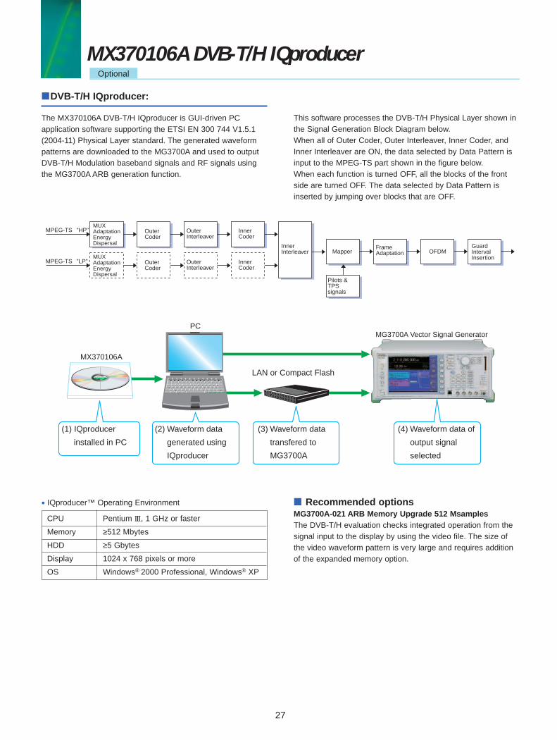
DVB-T/H IQproducer:
The MX370106A DVB-T/H IQproducer is GUI-driven PC application software supporting the ETSI EN 300 744 V1.5.1(2004-11) Physical Layer standard. The generated waveformpatterns are downloaded to the MG3700A and used to outputDVB-T/H Modulation baseband signals and RF signals usingthe MG3700A ARB generation function.
This software processes the DVB-T/H Physical Layer shown inthe Signal Generation Block Diagram below.When all of Outer Coder, Outer Interleaver, Inner Coder, andInner Interleaver are ON, the data selected by Data Pattern isinput to the MPEG-TS part shown in the figure below.When each function is turned OFF, all the blocks of the frontside are turned OFF. The data selected by Data Pattern isinserted by jumping over blocks that are OFF.
MPEG-TSMUXAdaptationEnergyDispersal
"HP"
MPEG-TS "LP"
Outer Coder
OuterInterleaver
InnerInterleaver
Inner Coder
MUXAdaptationEnergyDispersal
Outer Coder
OuterInterleaver
Inner Coder
Mapper
Pilots &TPS signals
FrameAdaptation OFDM
GuardIntervalInsertion
LAN or Compact Flash
PC
MX370106A
MG3700A Vector Signal Generator
(1) IQproducer
installed in PC
(2) Waveform data
generated using
IQproducer
(3) Waveform data
transfered to
MG3700A
(4) Waveform data of
output signal
selected
CPU Pentium III, 1 GHz or faster
Memory ≥512 Mbytes
HDD ≥5 Gbytes
Display 1024 x 768 pixels or more
OS Windows® 2000 Professional, Windows® XP
• IQproducer™ Operating Environment Recommended optionsMG3700A-021 ARB Memory Upgrade 512 MsamplesThe DVB-T/H evaluation checks integrated operation from thesignal input to the display by using the video file. The size ofthe video waveform pattern is very large and requires additionof the expanded memory option.
EQ_MX3701XIQpro_E700 12/13/06 4:06 PM Page 11

28
Physical Layer:Sets System,Transmission, Mode,Sub-carrier number,Bandwidth,Modulation Type andGuard Interval
Function:Sets• Outer Coder• Outer Interleaver• Inner Coder• Code Rate• Inner Interleaver
Data Pattern:Sets dataWhen "TS File" is selected, anarbitrary MPEG-2TS file (binarydata with remultiplexed videoand audio) is loaded to generatea waveform pattern. It is used forvideo evaluation.
DVB-H:Sets• In-depth Symbol Interleaver• Time Slicing• MPE-FEC
Filter:Multipath:
DVB-T/H IQproducer Main Screen
Parameters are set easily by selecting buttons on one screen.
DVB-T/H Measurement Image
The generated waveform pattern supports the following measurements.(1) Visual check using video pattern – General check of signal received from antenna to output at monitor(2) BER test based on ETSI TR 101 290 using module built into terminal – Receiver Sensitivity Test
All-in-One
DVB-T/H
• ISDB-T• WLAN• Bluetooth• GPS
MG3700A Vector Signal Generator
Pre-installed patterns
PC Controller
BER Test
Monitor Check When the video pattern is generated with DVB-T/H IQproducer, the customer's MPEG-2 TS file is required.
MX370106A DVB-T/H IQproducerOptional
EQ_MX3701XIQpro_E700 12/13/06 4:05 PM Page 8

29
No. Segment Items Setting Range Restriction∗ 1
1 System DVB-T, DVB-H2 Transmission Non-hierarchical, Hierarchical3 Alpha 1, 2, 4 1: When No.2 = Non-hierarchical4 Mode (Sub-carrier of OFDM) 2K, 4K, 8K "4K" cannot be set when No.1 = DVB-T.5 Bandwidth 5 MHz, 6 MHz, 7 MHz, 8 MHz "5 MHz" cannot be set when No.1 = DVB-T.6 Modulation Type QPSK, 16QAM, 64QAM "QPSK" cannot be set when No.2 = Hierarchical7 Guard Interval 1/4, 1/8, 1/16, 1/328 User Cell ID ON: 0000 to FFFF (hex), OFF "ON": When No.1 = DVB-H9 Outer Coder ON, OFF "LP" cannot be set when No.2 = Non-hierarchical.
OFF: When No.10 = OFF10 Outer Interleaver ON, OFF "LP" cannot be set when No.2 = Non-hierarchical.
ON: When No.9 = ONOFF: When No.11 = OFF
11 Inner Coder ON, OFF "LP" cannot be set when No.2 = Non-hierarchical.ON: When No.10 = ONOFF: When No.13 = OFF
12 Code Rate 1/2, 2/3, 3/4, 5/6, 7/8 "LP" cannot be set when No.2 = Non-hierarchical.Cannot be set when No.11 = OFF
13 Inner Interleaver ON, OFF ON: When No.11 = ON14 (Data) PN9, PN15, PN23, ALL0, ALL1, 0101, Null TS, TS File "LP" cannot be set when No.2 = Non-hierarchical.
When TS File is selected, the external TS file is read. The TS file is composed of several packetswith 188 bytes/packet. The first one byte of the packet becomes the Sync Byte and is set to 47(Hex).If a TS file that does not follow the format of this TS data is selected, an error is displayed when theCalculation button is clicked.When all of "Outer Coder," "Outer Interleaver," "Inner Coder," and "Inner Interleaver" are set to ON,Sync Byte is set to the data of "PN9/PN15/PN23/ALL0/ALL1/0101". At this time, the continuity of datais kept between the "last data of the packet" and the "first data of the next packet except the SyncByte." ∗ 2
15 Number of Super 1 to 384 (See next page for details.)Frames
16 In-depth Symbol ON, OFF OFF: When No.1 = DVB-TInterleaver OFF: When No.4 = 8K
OFF: When No.13 = OFF17 Time Slicing ON, OFF: OFF: No.1 = DVB-T
When Time Slicing = ON, the 49th bit of the "LP" cannot be set when No.2 = Non-hierarchical.TPS data is set to "1". When Data Pattern = TS File, Time Slicing processing is required in the selected TS file.
18 MPE-FEC ON, OFF: OFF: When No.1 = DVB-TWhen MPE-FEC = ON, the 50th bit of the TPS "LP" cannot be set when No.2 = Non-hierarchical.data is set to "1". When Data Pattern = TS File, MPE-FEC processing is required in the selected TS file.
19 (Type) None, Nyquist, Root Nyquist, Gaussian, Ideal Lowpass20 Roll Off/BT 0.100 to 1.000 Cannot be set when No.19 = None/Ideal Lowpass21 Symbol Length 1 to 1023 Cannot be set when No.19 = None/Ideal Lowpass
1: When No.19 = None1023: When No.19 = Ideal Lowpass
22 Multipath OFF, F1, P1
• Parameter Setting Items:
∗ 1: Other parameter setting conditions limited by setting range restrictions ∗ 2: Packet continuity shown in following figure
188 Byte 188 Byte
Sync ByteContinuous
DVB-H
Filter
Data Pattern
Function
PhysicalLayer
MX370106A DVB-T/H IQproducerOptional
EQ_MX3701XIQpro_E700 12/13/06 4:05 PM Page 7

30
Maximum Number of Super Frame Memory Option Mode384 2 k192 4 k96 8 k192 2 k96 4 k48 8 k
Number of Super Frame Setting
The "Number of Super Frame" setting range changes according to the "Mode" setting and "MG3700A main frame memory option" asshown in the following table.
Parameter Save/Recall
The numeric values and settings for each item can be saved ina parameter file. Input the name in the [File name] field andclick the [Save] button to save the parameter file. A saved parameter file is recalled by selecting it in the file list and clicking the [Open] button.
Graph Display
This function displays a generated waveform as a CCDF orFFT graph on the PC. It is useful for checking/reviewing waveforms before transfer to the MG3700A.
[Complimentary Cumulative Distribution Function (CCDF)graph]Up to 8 types of generated waveform can be read and displayedas CCDF graphs.
[Fast Fourier Transform (FFT) graph]Up to 4 types of generated waveform patterns can be read andthe transformed results displayed as FFT graphs.
The data selected by "Data Pattern" is anulled in the terminal of the final super frame set here. The data processing changes according to the "Size of TS File" and "Setting of Number of Super Frames" when TS File is selected at"Data Pattern". The TS File data is anulled when the "TS File data number" is greater than the "Data number equivalent to the setnumber of super frames." When the "TS File data number" is smaller than the "Data number equivalent to the set number of superframes," the same TS File data is repeated from the header.
TS File = x Byte
TS File = x Byte
Super Frame 1= y Byte
Super Frame n= y Byte
Super Frame n= y Byte
Super Frame 1= y Byte
Super Frame (n – 1)= y Byte
Data is annulled.
When x > n x y
When x < n x y
With Option 021 (ARB MemoryUpgrade 512 MSamples)
Without Option 021
MX370106A DVB-T/H IQproducerOptional
EQ_MX3701XIQpro_E700 12/13/06 4:05 PM Page 4

31
Model/Order No. Name Remarks— Main frame —
MG3700A Vector Signal Generator
— Standard accessories —
J0017F Power Cord, 2.6 m: 1 pcJ1276 LAN Straight Cable: 1 pc 10 cm, for U-link connection on rear panel
Compact Flash: 1 pc 64 MB min.J1254 Compact Flash Adapter: 1 pcZ0742 MG3700A CD-ROM: 1 pc Main frame operation manual, IQproducer operation manual, Standard
waveform operation manual, IQproducer software
— Options —
MG3700A-001 Rubidium Reference Oscillator Aging rate: +/–1 x 10–10/MonthMG3700A-002 Mechanical Attenuator Standard electronic attenuator changed to mechanical attenuatorMG3700A-011 Upper Frequency 6 GHz Extends standard frequency to 250 kHz to 6 GHzMG3700A-021 ARB Memory Upgrade 512 M Sample Extends 128 M sample/channel x 2 is to 256 M sample/channel x 2MG3700A-031 High-Speed BER Test function Extends standard BER Test functionMG3700A-101 Rubidium Reference Oscillator Retrofit Retrofit for shipped main frameMG3700A-102 Mechanical Attenuator Retrofit Retrofit for shipped main frameMG3700A-103 Electronic Attenuator Retrofit Retrofit for shipped main frameMG3700A-111 Upper Frequency 6 GHz Retrofit Retrofit for shipped main frameMG3700A-121 ARB Memory Upgrade 512 M Sample Retrofit Retrofit for shipped main frameMG3700A-131 High Speed BER Test Function Retrofit Retrofit for shipped main frame
— Maintenance service —
MG3700A-ES210 Extended Warranty Service 2 yearsMG3700A-ES310 Extended Warranty Service 3 yearsMG3700A-ES510 Extended Warranty Service 5 years
— Softwares (Waveform pattern) —
MX370001A TD-SCDMA Waveform PatternMX370002A Public Radio System Waveform Pattern RCR STD-39, ARIB STD-T61/T79/T86
— Softwares (License Key for IQproducer system) —
MX370101A HSDPA/HSUPA IQproducerMX370102A TDMA IQproducerMX370103A CDMA2000 1xEV-DO IQproducerMX370104A Multi-carrier IQproducerMX370105A Mobile WiMAX IQproducerMX370106A DVB-T/H IQproducer
— Optional accessories —
Z0777 Standard Waveform Pattern Upgrade Kit DVD 4 pcsW2495AE MG3700A Operation ManualW2496AE MG3700A IQproducer Operation ManualW2539AE MG3700A Standard Waveform Pattern Operation ManualW2533AE MX370001A TD-SCDMA Waveform Pattern Operation ManualW2503AE MX370101A HSDPA/HSUPA IQproducer Operation ManualW2504AE MX370102A TDMA IQproducer Operation ManualW2505AE MX370103A CDMA2000 1xEV-DO IQproducer
Operation ManualW2633AE MX370104A Multi-carrier IQproducer Operation ManualW2734AE MX370105A Mobile WiMAX IQproducer Operation ManualW2798AE MX370106A DVB-T/H IQproducer Operation ManualG0141 HDD ASSY Spare HDDK240B Power Divider (K connector) DC to 26.5 GHz, K-J, 50 Ω, 1 WmaxMA1612A Four-Port Junction Pad 5 MHz to 3 GHz, N-JMP752A Termination DC to 12.4 GHz, 50 Ω, N-PMA2512A Band Pass Filter For W-CDMA, pass band: 1.92 to 2.17 GHzJ0576B Coaxial Cord, 1.0 M N-P • 5D-2W • N-PJ0576D Coaxial Cord, 2.0 M N-P • 5D-2W • N-PJ0127C Coaxial Cord, 0.5 M BNC-P • RG-58A/U • BNC-PJ0127B Coaxial Cord, 2.0 M BNC-P • RG-58A/U • BNC-P
Please specify the model/order number, name, and quantity when ordering.
Ordering Information
EQ_MX3701XIQpro_E700 12/13/06 4:05 PM Page 3

Model/Order No. Name RemarksJ0127A Coaxial Cord, 1.0 M BNC-P • RG-58A/U • BNC-PJ0322A Coaxial Cord, 0.5 M SMA-P • SMA-P, DC to 18 GHz, 50 ΩJ0322B Coaxial Cord, 1.0 M SMA-P • SMA-P, DC to 18 GHz, 50 ΩJ0322C Coaxial Cord, 1.5 M SMA-P • SMA-P, DC to 18 GHz, 50 ΩJ0322D Coaxial Cord, 2.0 M SMA-P • SMA-P, DC to 18 GHz, 50 ΩJ1264 N-SMA Adapter N-P • SMA-JJ1261B Ethernet Cable (Shielded) Straight-through, 3 mJ1261D Ethernet Cable (Shielded) Crossover, 3 mJ0008 GPIB Cable, 2.0 mJ1277 IQ Output Conversion Adapter D-sub/BNCB0329C Front Cover for 1MW 4UB0331C Front Panel Handle Kit 2 pcs/setB0332 Joint Plate 4 pcs/setB0333C Rack Mount KitB0334C Hardtype Carrying Case With front cover and castersP0021 Compact Flash 128 MBP0022 Compact Flash 256 MBP0023 Compact Flash 512 MB
Trademarks• IQproducer is a registered trademark of Anritsu Corporation.• MATLAB is a registered trademark of The Math works, Inc.• CDMA2000® is a registered trademark of the Telecommunications Industry Association (TIA-USA).• Bluetooth and related logomarks are owned by Bluetooth SIG, Inc. and are used by Anritsu under license.
Other trademarks, etc., are the property of their respective owners.• Pentium® is a registered trademark of Intel Corporation in the USA and other countries.• Windows/Windows2000/WindowsXP is a registered trademark of Microsoft Corporation in the USA and other countries.• CompactFlash is a registered trademark of SanDisk Corporation in the USA and is licensed to the CFA (Compact Flash Association).• All other trademarks are the property of their respective owners.
Anritsu Corporation5-1-1 Onna, Atsugi-shi, Kanagawa, 243-8555 JapanPhone: +81-46-223-1111Fax: +81-46-296-1264
• U.S.A.Anritsu Company1155 East Collins Blvd., Richardson, TX 75081, U.S.A.Toll Free: 1-800-267-4878Phone: +1-972-644-1777Fax: +1-972-671-1877
• CanadaAnritsu Electronics Ltd.700 Silver Seven Road, Suite 120, Kanata, Ontario K2V 1C3, CanadaPhone: +1-613-591-2003 Fax: +1-613-591-1006
• Brazil Anritsu Eletrônica Ltda.Praca Amadeu Amaral, 27 - 1 Andar01327-010-Paraiso-São Paulo-BrazilPhone: +55-11-3283-2511Fax: +55-11-3288-6940
• U.K.Anritsu EMEA Ltd.200 Capability Green, Luton, Bedfordshire, LU1 3LU, U.K.Phone: +44-1582-433200 Fax: +44-1582-731303
• FranceAnritsu S.A.9 Avenue du Québec, Z.A. de Courtabœuf 91951 Les Ulis Cedex, France Phone: +33-1-60-92-15-50Fax: +33-1-64-46-10-65
• GermanyAnritsu GmbHNemetschek Haus, Konrad-Zuse-Platz 1 81829 München, Germany Phone: +49-89-442308-0 Fax: +49-89-442308-55
• ItalyAnritsu S.p.A.Via Elio Vittorini 129, 00144 Roma, ItalyPhone: +39-6-509-9711 Fax: +39-6-502-2425
• SwedenAnritsu ABBorgafjordsgatan 13, 164 40 KISTA, SwedenPhone: +46-8-534-707-00 Fax: +46-8-534-707-30
• FinlandAnritsu ABTeknobulevardi 3-5, FI-01530 VANTAA, FinlandPhone: +358-20-741-8100Fax: +358-20-741-8111
• DenmarkAnritsu A/SKirkebjerg Allé 90, DK-2605 Brøndby, DenmarkPhone: +45-72112200Fax: +45-72112210
• SpainAnritsu EMEA Ltd. Oficina de Representación en EspañaEdificio VeganovaAvda de la Vega, n˚ 1 (edf 8, pl 1, of 8)28108 ALCOBENDAS - Madrid, SpainPhone: +34-914905761Fax: +34-914905762
• United Arab EmiratesAnritsu EMEA Ltd.Dubai Liaison OfficeP O Box 500413 - Dubai Internet CityAl Thuraya Building, Tower 1, Suit 701, 7th FloorDubai, United Arab EmiratesPhone: +971-4-3670352Fax: +971-4-3688460
• SingaporeAnritsu Pte. Ltd.10, Hoe Chiang Road, #07-01/02, Keppel Towers,Singapore 089315 Phone: +65-6282-2400 Fax: +65-6282-2533
• P.R. China (Hong Kong)Anritsu Company Ltd.Suite 923, 9/F., Chinachem Golden Plaza, 77 Mody Road,Tsimshatsui East, Kowloon, Hong Kong, P.R. ChinaPhone: +852-2301-4980Fax: +852-2301-3545
• P.R. China (Beijing)Anritsu Company Ltd.Beijing Representative OfficeRoom 1515, Beijing Fortune Building, No. 5, Dong-San-Huan Bei Road, Chao-Yang District, Beijing 10004, P.R. ChinaPhone: +86-10-6590-9230Fax: +86-10-6590-9235
• KoreaAnritsu Corporation, Ltd.8F Hyunjuk Building, 832-41, Yeoksam Dong, Kangnam-ku, Seoul, 135-080, KoreaPhone: +82-2-553-6603Fax: +82-2-553-6604
• AustraliaAnritsu Pty. Ltd.Unit 21/270 Ferntree Gully Road, Notting Hill, Victoria 3168, AustraliaPhone: +61-3-9558-8177Fax: +61-3-9558-8255
• TaiwanAnritsu Company Inc.7F, No. 316, Sec. 1, Neihu Rd., Taipei 114, TaiwanPhone: +886-2-8751-1816Fax: +886-2-8751-1817
• IndiaAnritsu CorporationIndia Liaison OfficeUnit No. S-3, Second Floor, Esteem Red Cross Bhavan,No. 26, Race Course Road, Bangalore 560 001, IndiaPhone: +91-80-32944707Fax: +91-80-22356648
Specifications are subject to change without notice.
Catalog No. MX3701xxIQpro-E-A-1-(7.00) Printed in Japan 2006-12 W/CDT
061121
Printed on 70% Recycled Paper
EQ_MX3701XIQpro_E700 12/13/06 4:09 PM Page 32