mfmnmmmmLmmmFmmm UNLSIID MAY ANALYSIS N REDDY … · elements has generated considerable interest...
57
AD-A098 913 OKLAHOMA UNIV NORMAN F/6 11/4 ANALYSIS OF LAYERED COMPOSITE PLATES ACCOUNTING FOR LARGE DEFLE--ETC(U) UNLSIID MAY al .j N REDDY NOOOIR-78-C-0617 , mfmnmmmmLmmmFmmm EEEEEEmmmEEEEEE mmmmmmmmmm,
Transcript of mfmnmmmmLmmmFmmm UNLSIID MAY ANALYSIS N REDDY … · elements has generated considerable interest...

AD-A098 913 OKLAHOMA UNIV NORMAN F/6 11/4ANALYSIS OF LAYERED COMPOSITE PLATES ACCOUNTING FOR LARGE DEFLE--ETC(U)
UNLSIID MAY al .j N REDDY NOOOIR-78-C-0617, mfmnmmmmLmmmFmmm
EEEEEEmmmEEEEEEmmmmmmmmmm,

liii Ii ~ 2. 2
M( ROCP Rf (,LU 1WN ?Lt CHN


LEVELII
Department of the NavyOFFICE OF NAVAL RESEARCH
Structural Mechanics ProgramArlington, Virginia 22217
Contract NOOO14-78-C-0647-Project NR 064-609
Technical Report No. 21'
Report VPI-E-81-12
ANALYSIS OF LAYERED COMPOSITE PLATES ACCOUNTINGFOR LARGE DEFLECTIONS AND TRANSVERSE SHEAR STRAINS
by
J. N. ReddyDepartment of Engineering Science and Mechanics
Virginia Polytechnic Institute and State UniversityBlacksburg, Virginia, USA 24061
II
April 1981
Approved for public release; distribution unlimited
MAY 14 A1I41gN
A K

ANALYSIS OF LAYERED COMPOSITE PLATES ACCOUNTINGFOR LARGE DEFLECTIONS AND TRANSVERSE SHEAR STRAINS
J. N. Reddy
Department of Engineering Science and MechanicsVirginia Polytechnic Institute and State University
Blacksburg, VA 24061 USAApril, 1981
This paper is prepared forRECENT ADVANCES IN NONLINEAR COMPUTATIONAL MECHANICS
edited by E. Hinton, C. Taylor, and D. R. J. OwenPine Ridge Press, Swansea, United Kingdom
LIU

ANALYSIS OF LAYERED COMPOSITE PLATES ACCOUNTING FORLARGE DEFLECTIONS AND TRANSVERSE SHEAR STRAINS
J. N. Reddy
Department of Engineering Science and MechanicsVirginia Polytechnic Institute and State University
Blacksburg, VA 24061 USA
1. INTRODUCTION
In recent years composites, especially fiber-reinforcedlaminates, have found increasing application in manyengineering structures. This is mainly due to two desirablefeatures of fiber-reinforced composites: (i) the highstiffness-to-weight ratio, and (ii) the anisotropic materialproperty that can be tailored through variation of the fiberorientation and stacking sequence of lamina - a feature thatgives the designer an added degree of flexibility. Theincreased use of fiber-reinforced composites as structuralelements has generated considerable interest in the analysisof lamianted (anisotropic) composite plates.
Recent developments in the analysis of plates laminatedof fiber-reinforced materials indicate that the platethickness has more pronounced effect on the behavior ofcomposite plates than isotropic plates. The classical thin-plate theory (CPT) assumes that normals to the midsurfacebefore deformation remain straight and normal to themidsurface after deformation, implying that thickness sheardeformation effects are negligible. As a result, the naturalfrequencies, for example, calculated using the thin-platetheory are higher than those obtained by including thetransverse shear deformation effects. Also, the transversedeflections predicted by the thin-plate theory are lower thanthose predicted by a shear deformable theory (SOT). Due tothe low transverse shear modulus relative to the in-planeYoung's moduli, the transverse shear deformation effects areeven more pronounced in the composite plates. Thus a reliableprediction of the small deflection response characteristics ofhiqh modulus composite plates requires the use of sheardeformable theories.

2
When the transverse deflections experienced by plates arenot small in comparison with the plate thickness, theinteraction between membane stresses and the (bending andshear) curvatures of the plate must be considered. Theinteraction results in midplane stretching, which leads tononlinear terms in the equations of motion. Thus, a moreacccurate prediction of deflections, stresses, and frequenciesrequires the solution of the plate equations that account forlarge deflections and thickness shear deformation.
The present paper is concerned with a review of recentdevelopments in the finite-element analysis of layeredcomposite plates. The paper presents a shear deformabletheory that accounts for large rotations (in the von Karmansense), a finite element model of the equations, and finiteelement results (of linear and nonlinear theory) for staticbending and free vibration of rectangular plates. Thefollowing brief review, which cites the papers that haveappeared in the open literature on the linear and nonlinearbending and vibration of layered composite plates, provides abackground for the present paper.
A number of shear deformable theories for laminatedplates have been proposed to date. The first such theory forlaminated isotropic plates is due to Stavsky [1]. The theoryhas been generalized to laminated anisotropic plates by Yang,Norris, and Stavsky [2]. The Yang-Norris-Stavsky (YNS) theoryrepresents a generalization of Reissner-Mindlin plate theoryfor homogeneous, isotropic plates to arbitrarily laminatedanisotropic plates and includes shear deformation and rotatoryinertia effects. A review of various other theories, forexample, the effective stiffness theory of Sun and Whitney[3], the higher-order theory of Whitney and Sun [4], and thethree-dimensional elasticity theory of Srinivas et al. [5-7],can be found in the paper by Bert [8]. It has been shown(see, for example, [3,5,9-13]) that the YNS theory is adequatefor predicting the overall behavior such as transversedeflections and natural frequencies (first few modes) oflaminated anisotropic plates.
The first application of the YNS theory is apparently dueto Whitney and Pagano [14], who presented closed-formsolutions for symmetric and antisymmetric cross-ply and angle-ply rectangular plates under sinusoidal load distribution andfor free vibration of antisymmetric angle-ply rectangularplates. Fortier and Rosettos [15] analyzed free vibration ofthick rectangular plates of unsymmetric cross-ply constructionwhile Sinha and Rath [16] considered both vibration andbuckling for the same type of plates. Following Whitney andPagano [14], Bert and Chen [17] presented closed-form solutionfor the free vibration of simply supported rectanqular platesof antisymmetric angle-ply laminates.
A . . . . ,

3
Finite-element analysis of layered composite plates beganwith the works of Pryor and Barker [18], and Barker, Lin andDana [19], who employed an element with seven degrees offreedom (three displacements, two rotations and two shearslopes) per node to analyze thick laminated plates. Mau,Tong, and Pian [20], and Mau and Witmer [21] employed the so-called hybrid-stress finite element method to analyze thickcomposite plates. Using finite element models based on a formof Reissner's plate theory (i.e., 'mixed' formulation), Noorand Mathers [22,231 studied the effects of shear deformationand anisotropy on the response of lamiated anisotropic plates.One of the elements used by the authors (see [221) possesseseiqhty deqrees of freedom per element, and one cannot affordto use it without the luxury of having the enormouscomputational resources the authors had. Hinton [24,25]employed the so-called finite strip method to study theflexure and free vibration of layered cross-ply plates.Mawenya and Davies [26], and Panda and Natarajan [271 used thequadratic shell element of Ahmad, Irons and Zienkiewicz [28]to analyze bending of thick multilayer plates. Using twohybrid-stress elements, Spilker, Chou, and Orringer [291studied the static bending of layered composite plates. Thenumber of degrees of freedom in one of the elements isproportional to the number of layers, and therefore the corestorage and execution time requirements for the elementincrease rapidly with the number of layers in the plate.Recently, the present author developed a simple and efficientfinite element based on the YNS theory [30]. The elementcontains three displacements and two shear slopes as degreesof freedom per node. The accuracy and convergencecharacteristics of the element were investigated in [31]. Theelement has been used successfully in the thermoelasticanalysis of ordinary and bimodulus (i.e., different elasticproperties in tension and compression) layered compositeplates by the author and his colleagues [30-34].
Much of the previous research in the analysis ofcomposite plates is limited to linear problems. This may havebeen due to the complexity of the nonlinear partialdifferential equation associated with the large-deflectiontheory of composite plates. Approximate solutions to thelarge-deflection theory (in von Karman's sense) of laminatedcomposite plates were attempted by Whitney and Leissa [35],Bennett [36], Bert [37], Chandra and Raju [38,39], Zaqhlouland Kennedy [40], Chia and Prabhakara [41,42], and Noor andHartley [43]. Chandra and Raju [38,39], and Chia andPrabhakara [41,42] employed the Galerkin method to reduce thegoverning nonlinear partial differential equations to anordinary differential equation in time for the mode shape; theperturbation technique was used to solve the resultingequation. Zaghloul and Kennedy [40] used a finite-differencesuccessive iterative technique in their analysis. In all of

4
these studies, with the exception of [43], the transverseshear effects were neglected. The finite element employed byNoor and Hartley [43] includes the effect of transverse shearstrains; however, it is algebraically complex and involves alarge degree of freedom per element and thus one can precludethe use of such elements in the nonlinear analysis ofcomposite plates. Recently, the finite element developed in[30] by the author was extended to nonlinear bending ofcomposite plates [44,45].
Analysis of nonlinear vibration of single-layerorthotropic plates was considered by Ambartsumyan [46], andHassert and Nowinski [471. Nowinski [48,49] analyzedrectilinearly orthotropic plates of circular and triangularplanforms using Galerkin method. In these studies the effectof transverse shear deformation and rotatory inertia were notconsidered. Wu and Vinson [50] presented the dynamic analogueof Berger's equation of motion for an orthotropic plate,including the effect of transverse shear deformation androtatory inetia; however, the solutions were restricted toonly the transverse shear deformation. Mayberry and Bert [51]presented experimental as well as theoretical work onnonlinear vibration of laminated plates; however, thetheoretical investigation was limited to single-layerspecially orthotropic rectangular plate with all four edgesclamped, and not including the effect of transverse sheardeformation and rotatory inertia. Using an assumed mode shapeand Galerkin method, Nowinski [52] presented a generalequation for the nonlinear analysis (i.e., large deflectionand large amplitude free vibration) of orthotropic plates (seealso, Sathyamoorthy and Pandalai [53]). Prabhakara and Chia[54] presented an analytical investigation of the nonlinearvibration of a rectangular orthotropic plate with all simplysupported and all clamped edges. The effect of transverseshear and rotatory inertia on large amplitude vibration ofcomposite plates was reoorted recently by Sathyamoorthy andChia [55-57] using Galerkin method and the Runge-Kuttanumerical procedure.
Layered composite plates exhibit, in general, couplingbetween the in-plane displacements and the transversedisplacement and shear rotations. For plates having layersstacked symmetrically with respect to the mid-plane, thebending-stretching coupling terms vanish and the problembecomes relatively simpler. Wu and Vinson [58] extended theirearlier work [50] to deal with the nonlinear vibration ofsymmetrically stacked laminated composite plates. The firstnonlinear vibration analysis of unsymmetrically laminatedplates is due to Bennett [36], who considered simply supported(with immovable edges) angle-ply plates. Using the thin platetheory of layered composite plates and Galerkin method, Bert[37] investigated the nonlinear vibration of a rectangularplate arbitrarily laminated of anisotropic material. A

5
multimode (two-term) solution for nonlinear vibration ofunsymmetric all-clamped and all-simply supported angle-ply andcross-ply laminated plates was reported by Chandra and BasavaRaju [38,39,59]. Chandra [39] used a one-term Galerkinapproximation for the dynamic von Karman plate equations andthe perturbation technique for the resulting ordinary equationin time to investigate the large-amplitude vibration of across-ply plate which is simply supported at two oppositeedges and clamped at the other two edges. Prabhakara and Chia[54] presented an analytical investigation of the nonlinearfree flexural vibrations of unsymmetric cross-ply and angle-ply plates with all-clamped and all-simply supported edges.The normal and tangential boundary forces in the plane of theplate were assumed to be zero. Tn all of these studies, theeffects of shear deformation and rotatory inertia wereneqlected, and only rectangular geometries were considered.The latter restriction is a direct result of the methods ofanalysis used (i.e., Galerkin method, perturbation method andthe double series method cannot be applied to plates ofcomplicated geometries). Recently, the present author [60]investigated the nonlinear vibration of layered compositeplates using the finite element method.
2. GOVERNING EQUATIONS ([45,60])
Consider a (thick) plate of uniform thickness h,laminated of anisotropic layers with the material axes of eachlayer being arbitrarily oriented with respect to the midplaneof the plate. The midplane of the plate, denoted by P, formsthe x-y plane of the coordinate system, with the z-axisperpendicular to the midplane of the plate. In order toaccount for the midplane stretching due to large deflections,the shear deformable theory of Whitney and Pagano [14] ismodified to include large rotations (in the von Karman sense).The displacement field is assumed to be of the form,
ui(x,y,z,t) = u(x,y,t) + z x(X'y't)
u2(x,y,z,t) = v(x,y,t) + Z wy(X,y,t), (1)
u3(x,y,z,t) = w(x,y,t).
Here t is the time; u2, u2, u3 are the displacements in x, y,z directions, respectively; u, v, w are the associatedmidplane displacements; and * and *y are the slopes inthe xz and yz planes due to bending only. Assuming that theplate is moderately thick and strains are much smaller thanrotations, the nonlinear strain-displacement relations can beexpressed in the formi,
X= + 2 + Z - l + Z 1
........ +

6
3v (3W 2 oy= N 2y + Z - E2 + Z K2
Du +av +aw aw+ z(8x + 0
IF = + aw $ C4 +(2)5 x y + Y
wherein the products of x, aul/ax and 3u2/3y areneqlected. Since the constittive relations, to be givenshortly, are based on the plane-stress assumption, strain edoes not come into the equations.
Neglecting the body moments and surface shearing forces,we write the equations of motion (in the absence of surfaceand body forces) as,
Ni,x + N ,y = Putt + R~px,tt
N6 ,x + N ,y = Pv tt + Ry,tt
Q1,x + Q2,y + N(Ni,w) = Pwtt (3)
Mix + M 6,y - Q, = I~xjtt + Rutt
M 6,x + M 2,y - Q2 = I yjtt + Rv,tt
where P, R, and I are the normal, coupled normal-rotatory, androtatory inertia coefficients,
(P,R,I) h (l,z,z2)pdz 4 (l,z,z 2 )I-h/2 mfzm
p(m) beinq the material density of the m-th layer, Ni, Qi, and
Mi are the stress and moment resultants defined by
(Ni,Mi) _h/2(l,z)oi dz , (QIQ 2) = h/2 ( , CO)dz,IJ-h2 1 I -h/2 (5)
and N(.) is the nonlinear operator,
N(w,Nij) = 3 (N, aw) + 3y (N6 a)+ (N6 )+
Here oi (i = 1,2.. .6) denotes the in-plane stress components(a, = Ox, 02 = 0y, a4 = ayz' '5 = Oxz and a6 = Oxy).
Assuming the existence of one plane of elastic symmetryparallel to the plane of each layer, the constitutiveequations for the m-th layer (in the plate coordinates) aregiven by
7
01 1 )] [Qi (in
02 = [Q'] 2j1 = Lo) " ) I , 6I ()~)sj C
4 44 ° L Q4 52(m )I
Q( ) ( ma b 6 0~ 5 45 Q55 5 s
where QT) are the stiffness coefficients of the m-th layer inthe plat coordinates. Combining eqns. (5) and (6), we obtainthe plate constitutive equations,
N i A i j B i j ] 1 Q 2 1 = A 4 A 4 51 1 C 4
1i Bji Dij j ' i i = [A45 A55]f5:
(7)
The A.- (i,j = 1,2,6), and A.- (i,j = 4,5) are therespecive nplafe, bending-plane coupling, bending ortwisting, and thickness-shear stiffnesses, respectively:
Ai BiDi j ) = fZm+l()
A EZm+kikjQ(I )dz. (8)Aij =mfzm i I
Here zm denotes the distance from the mid-plane to the lowersurface of the m-th layer, and ki are the shear correctioncoefficients.
Equations (3) and (7) must be adjoined by appropriateboundary conditions of the problem. The variationalformulation of these equations indicate the followingessential and natural boundary conditions:
essential: specify, un, Us, w, no *s((9)
natural: specify, Nn, Nns, q, Mn, Mns.
wherein un and us, for example, denote the normal andtangential components of the in-plane displacement vector, U,(uv).
3. FINITE ELEMENT MODEL ([44,45,60])
The equations presented in the previous section are validfor any arbitrarily laminated composite plate. Except undercertain special conditions of geometry, boundary conditionsand stacking of layers, these equations do not admit exactsolutions (in fact, exact closed-form solutions cannot be

8
obtained without invoking small-displacement assumption; see[29]). Here we present a finite-element model associated withthe equations governing the nonlinear analysis of layeredcomposite plates. The element is an extension of the penaltyplate-bending element developed for the linear analysis oflayered composite plates by the author [28,29].
Consider a finite-element analogue, V, of the midplane ofthe plate, R. Over a typical element IRe of the mesh R atypical generalized displacement, U, is interpolated in spaceby expression of the form,
nU = i i (10)
where UI is the value of U at node i, pi is the finite-elementinterpolation function at node i and n is the number of nodesin the element. For simplicity, we use the same interpolationfor each of the generalized displacements.
The weak form of eqns. (3) and (7) over a typical element
is given by
0=Re { 6u (Pu , tt+R x,tt)+ 6u,xN i+ 6uyN6+6v(Pvtt+Rl ytt)
+ 6v xN6+6v,yN 2+6w Pw,tt)+'w, xQi+6wyQ2+ 76w aw N+ -6w 3wN +a6w aw N +6w awN
+ 64x(Ix,tt+Rutt)+6%x'xMj+,x yM6 +6 xQi
+ 6 y(Iqy,tt+Rvtt)+6 y,xM6+ Py,yM2+6 yQ2} dxdy
+ fC (6unNn+6usNns)ds+ 6wqds+m 6nMn +6sMns)dS,n q m
(11)
where Ni, Mi, and Qi are given in terms of the generalizeddisplacements by eqn. (7). The boundary terms Nn, Ns q, Mn,and M (notation used is very standard) in eqn. (l. getcanceled at interelement boundaries, and equal to thosespecified at the plate boundary.
Let u, v, w, *x, and *y be approximated over each elementby
u = UT(t), v = VT(t), w = WX(t), *x = XP(t), *y = YU(t)
(12)where U, V, etc., are given by ean. (10), and T(t), x(t), andP(t) are time dependent functions whose specific form is to

9
be determined. Substituting eqns. (10) and (12) into eqn.(11), we obtain the following element equation:
[K](A} + [M]{A} = (F} (13)
Here Al is the column vector of the nodal values of thegeneralized displacements, [K] is the matrix of stiffnesscoefficients (which depends on the qeneralized displacements),[M] is the matrix of mass coefficients, and {Fl is the columnvector containing the boundary contributions. The elements of[K] and [M] are given in Appendix B. It should be noted from[K] in the appendix that the time functions are not harmonic.That is, strictly speaking, eqn. (13) must be solved as oneof transient equation (even in the case of free vibrations).However, in the present analysis we assume, for simplicity,that
T= X = 2 = cos 2 Wt (14)
and retain only the first term of the cosine series. Thisassumption yields the standard eigenvalue problem in the caseof natural vibration:
([K] - W2[M]){A} = t0}. (15)
The solution procedure consists of a direct iteration, inwhich the global stiffness [K] is updated using the globaldisplacement (eigen function) vector Al from the previousiteration. If {A is set to zero (as was done in the presentanalysis) at the beginning of the iteration procedure, weobtain the linear solution (frequencies) of the problem at theend of the first iteration. The iteration is terminated whenthe nonlinear solution (frequencies) obtained during twoconsecutive iterations differ by some small number (say,one percent).
In the present study linear (4-node) and quadratic (8-node and 9-node) isoparametric elements are employed. Theelement stiffness matrices are of the order 20 x 20, 40 x 40,and 45 x 45 respectively.
As pointed out in [30,61], the shear deformable theorypresented herein can be derived from the classical thin platetheory by using the penalty function method to incorporate theslope-displacement relations
aw : _ex w = -y
as constraints into the variational formulation of the thinplate theory. It is well-known that reduced integration mustbe used in the numerical solution of penalty functionproblems. In other words, the shear energy terms (whichcorrespond to the penalty functional) in the element matrices
10
must be underintegrated. This means that a lxl Gauss rulemust be used in place of the standard 2x2 Gauss rule in theevaluation of the stiffness coefficients associated with theshear enerqy for the four-node element. For more details onthe reduced integration in plates, see [62,63].
6. NUMERICAL RESULTS AND DISCUSSION
The finite element presented herein was employed in thenonlinear analysis of rectangular plates. The followingmaterial properties typical of advanced fiber-reinforcedcomposites were used in the present study:
Material I: El/E 2=25, G1 2/E2=O.5, G22/E =0.2, V12=0.25
Material II: EI/E 2=40, G,2/E 2= 0.6, G2 3/E2= 0.5, v12=0.25
(16)
It is assumed that G 13 G23 and v = V. A value of 5/6was used for the shear correction coefficients, k4
2=k 52 (seeWhitney [64]). All of the computations were carried on an IBM370/158 computer in double precision.
6.1 Static Bending Results ([30,31,44,45]).
To show the effect of the reduced integration, and toillustrate the accuracy of the present element, results of thelinear analysis are presented. Numerical experiments wereconducted to investigate the effect of element type (i.e.,linear, eiqht-node quadratic, and nine-node quadratic), mesh(L2 = linear 2 by 2, Q2 = 2Q8 = 8-node quadratic 2 by 2elements in quarter plate), and reduced integration on thedeflections and stresses.
In Table 1 linear and quadratic elements are compared fordeflections and stresses of a three-layer (h, = h3 = h/4, h2 =h/2) square plate (material I) subjected to sinusoidalloading. This problem is also equivalent to a four-layer(equal thickness) cross-ply laminate. The following boundaryconditions were used (in the finite element method only theessential boundary conditions were imposed):
uo(x,O) = uo(x,b) = 0, N2(x,O) = N2(x,b) = 0
v0 (O,y) = vo(a,y) = 0, N1(O,y) = Nl(a,y) = 0
SS-1: w(x,O) = w(x,b) = w(O,y) = w(a,y) = 0 (17)
4x(x,O) = ox(x,b) = 0, M2(x,O) = M2(x,b) = 0
4y(Oy) = *y(a,y) = 0, M1(O,y) = M1(a,y) = 0

9
be determined. Substituting eqns. (10) and (12) into eqn.(11), we obtain the following element equation:
[K]{A} + [M]{A} = (F} (13)
Here {A} is the column vector of the nodal values of thegeneralized displacements, [K] is the matrix of stiffnesscoefficients (which depends on the generalized displacements),[M] is the matrix of mass coefficients, and {F) is the columnvector containing the boundary contributions. The elements of[K] and [M] are given in Appendix B. It should be noted from[K] in the appendix that the time functions are not harmonic.That is, strictly speaking, eqn. (13) must be s~'Wed as oneof transient equation (even in the case of free vibrations).However, in the present analysis we assume, for simplicity,that
T= A2 = COS 2 Wt (14)
and retain only the first term of the cosine series. Thisassumption yields the standard eigenvalue problem in the caseof natural vibration:
([K] - W2[M]){A} = {0}. (15)
The solution procedure consists of a direct iteration, inwhich the global stiffness [K] is updated using the globaldisplacement (eigen function) vector {A} from the previousiteration. If {A} is set to zero (as was done in the presentanalysis) at the beginning of the iteration procedure, weobtain the linear solution (frequencies) of the problem at theend of the first iteration. The iteration is terminated whenthe nonlinear solution (frequencies) obtained during twoconsecutive iterations differ by some small number (say,one percent).
In the present study linear (4-node) and quadratic (8-node and 9-node) isoparametric elements are employed. Theelement stiffness matrices are of the order 20 x 20, 40 x 40,and 45 x 45 respectively.
As pointed out in [30,61], the shear deformable theorypresented herein can be derived from the classical thin platetheory by using the penalty function method to incorporate theslope-displacement relations
aw = .x aw = -y
as constraints into the variational formulation of the thinplate theory. Tt is well-known that reduced integration mustbe used in the numerical solution of penalty functionproblems. In other words, the shear energy terms (whichcorrespond to the penalty functional) in the element matrices
11
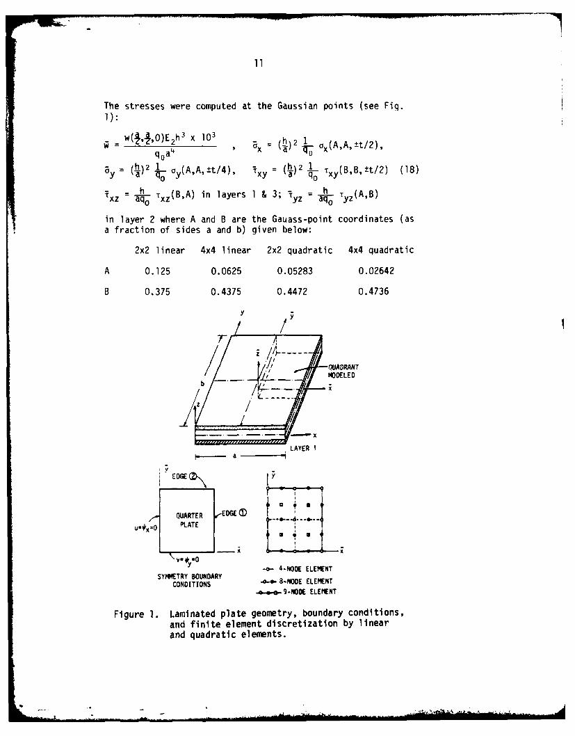
The stresses were computed at the Gaussian points (see Fig.1):
w(,OE X 103 (h)2 1 AEAO
q0a4 Bx q h x(AA't/2)
= (.) . o(A,A, ±t/4), 1 1 .) Txy(BB,±t/2) (18)y oY y a - h
Txz - Txz(B,A) in layers 1 & 3; ! aq° Tyz(A,B)
in layer 2 where A and B are the Gauass-point coordinates (asa fraction of sides a and b) given below:
2x2 linear 4x4 linear 2x2 quadratic 4x4 quadratic
A 0.125 0.0625 0.05283 0.02642
B 0375 0.4375 0.4472 0.4736
b ~ -MODELED
b!
LAYER Ia -
EDGE ..
INi
QUARTER -EDGE .
U-*x-O PLATE
V.* "0y(
-o- 4-NODE ELEMENTSYMMETRY BOUNDARY
CONDITIONS .o..- B-NODE ELEMENT--o- 9-NODE ELEMENT
Figure 1. Laminated plate geometry, boundary conditions,and finite element discretization by linearand quadratic elements.
4i. .

12
Table I Effect of reduced integration on the maximum deflec-tion and stressesofathree-ply (00/90*/0 ") squareplate subjected to sinusoidal loading (h,=h3=h/4,h2=h/2, material I).
a/h Source a Bx ay Txy Txz iyz
3-DES [11] 7.434 0.599 0.403 0.0276 0.301 0.196CFS [31] 6.627 0.496 0.359 0.0240 0.414 0.128Ref. [27] 6.299 0.532 0.307 0.0250 .. ..4Q8-R 6.627 0.495 0.359 0.0240 0.414 0.1284L-R 6.599 0.467 0.347 0.0227 0.395 0.2084L-F 6.427 0.451 0.328 0.0219 347.5 247.2
10 2Q8-R 6.615 0.484 0.351 0.0234 0.404 0.1262Q8-F 6.605 0.483 0.349 0.0234 0.404 0.1262Q9-R 6.561 0.480 0.341 0.0231 0.400 0.1262Q9-F 6.551 0.479 0.340 0.0231 0.399 0.1262Q9-FR 6.558 0.480 0.341 0.0230 0.400 0.1262L-R 6.508 0.380 0.284 0.0187 0.355 0.1072L-F 5.901 0.334 0.245 0.0163 261.6 261.43-UtS FlIU 5.173 0.543 0.308 0.0230 0.328 0.156CFS [31] 4.911 0.524 0.294 0.0219 0.434 0.108Ref. [27] 4.847 0.557 0.307 0.0231 -. ..4Q8-R 4.911 0.524 0.294 0.0219 0.434 0.1084L-R 4.863 0.494 0.278 0.0207 0.415 0.1034L-F 4.346 0.437 0.245 0.0183 115.5 115.3
20 2Q8-R 4.091 0.511 0.287 0.0214 0.424 0.1062Q8-F 4.876 0.508 0.284 0.0214 0.424 0.1062Q9-R 4.847 0.505 0.278 0.0213 0.418 0.1062Q9-F 4.827 0.502 0.275 0.0211 0.418 0.1072Q9-FR 4.847 0.505 0.278 0.0212 0.417 0.1062L-R 4.712 0.404 0.229 0.0170 0.353 0.0892L-F 3.236 0.265 0.149 0.0111 70.55 70.43-DES [1] 4.385 0.539 0./1 0.0214 0.339 0.139CFS [31] 4.337 0.535 0.269 0.0212 0.442 0.100Ref. [27] 4.363 0.566 0.284 0.0223 .. ..4Q8-R 4.336 0.535 0.269 0.0212 0.442 0.1004L-R 4.281 0.505 0.254 0.0200 0.422 0.096
100 4L-F 1.034 0.120 0.060 0.0048 9.327 9.4042Q8-R 4.319 0.521 0.262 0.0206 0.435 0.1022Q8-F 4.143 0.490 0.244 0.0199 0.430 0.1002Q9-R 4.301 0.418 0.255 0.0207 0.428 0.0992Q9-F 4.158 0.490 0.242 0.0201 0.427 0.1002Q9-FR 4.299 0.518 0.255 0.0206 0.426 0.0992L-R 4.107 0.413 0.208 0.0164 0.356 0.0822L-F 0.315 0.003 0.015 0.0012 2.173 2.192
classical thin-plate solution 4.350 0.539 0.269 0.213 0.339 0.138

13
In Table 1, R denotes reduced integration, F = fullintegration, and FR = full integration for bending terms, andreduced integration for the shear terms. The followingobservations can be made from the results of Table 1.
1. The nine-node element gives virtually the sameresults for full (3x3 Gauss rule), reduced (2x2 Gaussrule), and mixed (3x3 and 2x2 Gauss rules)integrations. However, the results attained by usingthe reduced integration are the closest of all threeintegrations to the closed-form solution [31].
2. The nine-node element and the eight-node element(with reduced integration) give almost identicalresults (contrary to the belief that the nine-nodeelement is superior to the eight-node element) forall side-to-thickness ratios.
3. Integration rule has a more profound effect on theaccuracy in the eight-node element than in the nine-node element. Full integration gives less accurateresults than the reduced integration, and the errorincreases with the side-to-thickness ratio. Thisimplies that the reduced integration is a must forthin plates, as generally recognized for all penalty-function based finite element models.
4. Full integration results in, relatively, smallererrors for quadratic elements and for refined meshesthan for linear elements and/or for coarse meshes.That is, the error between the solutions obtained by2Q8-F and 2Q8-R is smaller than those obtained by 4L-F and 4L-R, and the error between the solutionsobtained by 4L-F and 4L-R is smaller than thoseobtained by 2L-F and 2L-R.
5. Numerical convergence of the element is clear fromthe results.
It should be pointed out that the present finite-elementsolutions are not expected to agree exactly with the 3-Delasticity solution, because the element is based on the YNStheory rather than the 3-0 elasticity equations. The accuracyof the YNS theory is evident from the results. While the YNStheory seems to predict the maximum deflection very close tothat given by the 3-0 elasticity solution, the stresses,especially the transverse shear stresses, are not in goodaqreement for thick plates. The stresses predicted by the YNStheory are on the lower side of the 3-D elasticity results.
In the results to be presented, reduced inteqration wasused with linear and quadratic elements.

14
c,.0 C : C:(: LA:J s o:)CD --oCienC~ C) C:) C
0) 00D %Dr - oOO'0 0 0- ~c i-0 u 0 40
C) C)C)C CO )) 16C > c 6c. - C)J LA C C.J ( A C
0-Ic Nn ;r0 O \J' C0I0 -0 - - -CQ C~
0.; C). C) 0D ,6C 61;
CD 0
00 v) 10 .\ -m Cj~ c) l ?o:: 00 ) v- 100 O~k at U-)c
- ~ Ci CI~LA C'J-Cj ,-7. - - - -
Q) \cC'.C\IC 4=11 (\C%C C :>= C C ) 6 ('.C1.. 6 %J 6
LA 0 Icr-. (%n C O aLnc r) u-) LA ') C..J CO Iu IO t~ L AO 0qL
Ln- 0~ 0=C oC C IC )CC : )C ))C
4-)v
-0) 00a~ ~ ~ 00)3 N 0 O i CDN zrO~
to E0 C'- %Di to ko 0nC0 en (i ed n m 0N eI t tot I * C rI 0) r * tI L
C)- . * C
) CD 0
OE c - mb Mb~ m )- i ~~ n
toe 0 00 00 0L 00 0 0 'a
Z" aa c t .
00 CO- 00)0+j
4-- -o - 0) )
00 0 0, r o 0 0i- 'vE r IA (U a) di c .
00 ea o
Il" u - 0 - u - 01L- C- 4-L- u l
2 C) Cc ) ) 0) I S.to olln LC) A A 0 A I
0 ~ 0 ~ 4
15
In Table 2, the 3-D elasticity solution of Pagano [10]the closed-form solution [31] and 4Q8 and 2Q8 finite-
element results (FEM) are compared for three-layer(0*/90*/0*), equal thickness, square plate (material I). Thepresent finite-element results are in excel agreement with theclosed-form solution of the equations governing the YNStheory. The stresses in 3-D elasticity solution were reportedto be maximum at the following points:
ax = ax(J,4,±h/2) , ay = By(,,h/4) xy xy(a,bh)
rxz = 1xz(aq,0) , lyz = ivz(,b O ) (20)
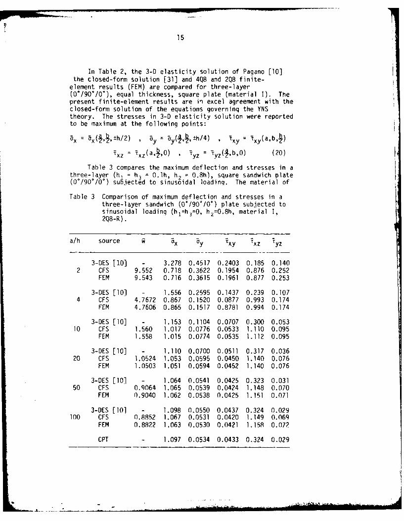
Table 3 compares the maximum deflection and stresses in athree-layer (h1 = h3 = 0.lh, h2 = 0.8h), square sandwich plate(0e/90°/0*) subjected to sinusoidal loading. The material of
Table 3 Comparison of maximum deflection and stresses in athree-layer sandwich (0°/90°/0 °) plate subjected tosinusoidal loading (hl=h3=0, h2=0.8h, material I,2Q8-R).
a/h source Q Ox ay Txy Txz Tyz
3-DES [10] - 3.278 0.4517 0.2403 0.185 0.1402 CFS 9.552 0.718 0.3622 0.1954 0.876 0.252
FEM 9.543 0.716 0.3615 0.1961 0.877 0.253
3-DES [101 - 1.556 0.2595 0.1437 0.239 0.1074 CFS 4.7672 0.867 0.1520 0.0877 0.993 0.174
FEM 4.7606 0.865 0.1517 0.8781 0.994 0.174
3-DES [10] - 1.153 0.1104 0.0707 0.300 0.05310 CFS 1.560 1.017 0.0776 0.0533 1.110 0.095
FEM 1.558 1.015 0.0774 0.0535 1.112 0.095
3-DES [10] - 1.110 0.0700 0.0511 0.317 0.03620 CFS 1.0524 1.053 0.0595 0.0450 1.140 0.076
FEM 1.0503 1.051 0.0594 0.0452 1.140 0.076
3-DES [10] - 1.064 0.0541 0.0425 0.323 0.03150 CFS 0.9064 1.065 0.0539 0.0424 1.148 0.070
FEM 0.9040 1.062 0.0538 0.0425 1.151 0.071
3-DES [101 - 1.098 0.0550 0.0437 0.324 0.029100 CFS 0.8852 1.067 0.0531 0.0420 1.149 0.069
FEM 0.8822 1.063 0.0530 0.0421 1.15P 0.072
CPT - 1.097 0.0534 0.0433 0.324 0.029
16
the face sheets (i.e., layers I and 3) is the same as materialI, and the core material is transversely isotropic withrespect to z and is characterized by the followinq properties(see Pagano [10]),
Ej/E 2 = 1.0 E3/E 2 = 12.5 (not used in YNS theory)(21)
G1 3/G 2 3 =l.5E2 , G 12 :0.4 E2 , v1 2=v1 3=v 2 3 =0.25
The finite-element results are in good agreement with theclosed-form solution; however, the YNS theory seems to predictthe stresses quite low for thick plates.
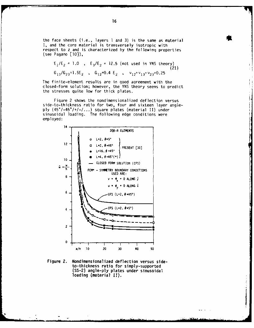
Fiqure 2 shows the nondimensionalized deflection versusside-to-thickness ratio for two, four and sixteen layer angle-ply (45°/-45°/+/-/...) square plates (material II) undersinusoidal loading. The following edge conditions wereemployed:
14 -2Q8-R ELEMENTS
o L%2. 0-5°
12 0 L2, 4 °5' PRESENT [30]
e L-16, 0 -45°
1 L%4, 9-45'(*)10_ - CLOSED FORM SOLUTION (CFS)
hW FEW - SYMMETRY BOUNDARY CONDITIONSUSED ARE:
v - 0 ALONG
u - #y 0 ALONG
6CFS (L-2,G. 45')
0 (L-2. 9.5")CFS (L-2. 0-5*)
2 1.
00
II
0. I ' I I '
a/h 10 20 30 40 50
Figure 2. Nondimensionalized deflection versus side-to-thickness ratio for simply-supported(SS-2) angle-ply plates under sinusoidalloading (material II).
I

17
uO(Oy) = uo(a,y) = 0 , N6 (0,y) = N6 (a,y) 0
Vo(x,O) = v0 (x,b) = 0 , N,(x,O) = Nb(x,b) 0
SS-2: w(x,O) = w(x,b) = w(O,y) w(a,y) = 0 (22)
x(x,O) = x(x,b) = 0 , M2(x,O) = M,(x,b) = 0
'y(OY) = 'y(a,y) = 0 , MI(O,y) = M,(a,y) = 0
Dark lines and symbols correspond, respectively, to theclosed-form solution and the finite-element solution (with thesymmetry conditions of the CFS imposed). The finite elementsolutions are in excellent agreement with the closed formsolution.
Having established the credibility of the finite elementpresented herein for the linear analysis of layered compositeplates, we now employ the element in the nonlinear analyses.
First, results are presented for single-layer isotropic squareplates under uniform loading. The essential boundaryconditions used are (BC3 and BC5 in Table 4):
simply-supported (SS-3): u=v=w=O on all edges. (22)
u=v=w=O on all edges,
clamped (CC-l): v =0 along edgesp~rallel to x-axis, (23)
*x=O along edgesparallel to y-axis.
Figures 3 and 4 show the nondimensionalized center deflection,= w/h, and nondimensionalized center stress, a = aa2/Eh2, as
a function of the load parameter, P = qna4/Eh 4 for simply-supported (SS-3) square plate, under uniformly distributedload. Figure 5 shows similar results for clamped (CC-l)square plate under uniformly distributed load. The resultsare compared with the Ritz solution of Way [65], doubleFourier-series solution of Levy [66], the finite-differencesolution of Wang [67], the Galerkin solution of Yamaki [68],and the displacement finite-element solution of Kawai andYoshimura [69]. Finite-element solutions were computed forthe five degrees of freedom (NDF = 5), and for three degreesof freedom (NDF = 3); in the latter case, the in-planedisplacements were suppressed. Since suppressing the in-planedisplacements stiffens the plate, the deflections are smallerand stresses are larqer than those obtained by including thein-plane displacements. Solutions of the other investiqatorswere read from the graphs presented in their papers. The

18 i
2.0.
1.6-
1.2-
0 o 2x2 LINEAR (N0F-3)
0.8- * 2x2 LINEAR (NDF-S5)0. t
a 2x2 QUADRATIC (NDF-3)
a 2x2 QUADRATIC (NDF5)
0.4 /- YAMAKI [68]-- LEVY [66)
WANG [67)
, -. ,, I' I ' "
P 50 100 150 200 250
q0(a/h) 4/E
Figure 3. Load-deflection curves by various investigatorsfor simply-supported (SS-3) square plate underuniformly distributed load.
12
Oa2 --- LEVY £66]Eh2 - WANG [671 .0o- *
:1 - o 2x2 LINEAR (NDF-3)
* 2x2 QUADRATIC (NOF-3)
0 W LINEAR (NDF5)•2x2 QUA ;TC (NOF-S)
P 50 100 150 200 250
4P* qo(a/h) /E
Figure 4. Nondimensionalized center stress versus theload parameter for simply supported (SS-3)square plate under uniformly distributedload.

19
2. -_ YAMAKI £68]
WAY £65] 81.6 -- KAWAI and YOSHIIJRA £691 8
1.2-8
.8 0 2x2 LINEAR (NOF - 3)O / P REENT 2x2 LINEAR (NOF 51)
/ 22 QUADRATIC (NOF 3)
4 - 2 QUADRATIC (NDF - 5)
0 l I I I
A 50 100 1SO 200 250
- q0(a/h)4 /E
(a) Load-deflection curves
Figure 5. Nondimensionalized center deflection and stressversus the load parameter for clamped (CC-l)square plate under uniformly distributed load.
*a2
- YAMAKI [68]E-WAY [651
16 -- KAWAI and YOSHIMURA £69] 0
120
o 4x4 LINEAR (NOF - 3)4 / * 4x4 LINEAR (OF - 5)
a 2x2 QUADRATIC (NOF - 3)
a 2x QUADRATIC (NOF - 5)
O oI I • l ' f ' ! " "
P 50 100 150 200 250 300
P • qo(a/h) 4/E
(b) center stress versusload parameter

20
present solutions are in good agreement with the results ofother investigators.
Table 4 Types of boundary conditions used in the presentstudy.
Notation Description of essential boundary conditions.(Type) ..........
side I side 2
BC(SS-I) v w y :0 u w = x 0
BC2(SS-2) u =W y 0 v w = x= 0
BC3(SS-3) u v = w 0 u = v = w = 0
BC4(SS-4) u V w = w 'y : 0 u : v = w = =x 0
BC5(CC-i) u v w =x 0 u = v = w =y = 0
BC6(CC-2) u v w = = y 0 u v = w : * :y : 0
BC7(CC-3) u w x :0 v = w :y 0
BC8(CC-4) w Ipx 0 W = y 0
Table 5 shows noodimensionalized center deflection Q =w A, center stress a' = oa 2/Eh2, and edge stress = cr( ,O~a2/Eh2 of aclamped fCC-2f square plate under uniformly
distributed load, qo. The boundary conditions are of typeBC6,
CC-2: u = v = w = x y = 0 alona all edges. (24)
The present solution is obtained using a 2 by 2 uniform mesh(in quarter plate) of nine-node isoparametric elements (2Q9)with (R) and without (F) reduced integration. The presentsolution for center deflection and stresses agree very closelywith the finite element solution of Pica et al. [70], and theanalytical solution of Levy [71]. The edge stress, for somereason, does not agree with the other two results.

21
(V a r- 06 c l'..,m; ;U,
Eeo
N %Dk ?,U) n0 L j
oo X , i
0o X~-100
.1) m ~ iro 0C) ,o n ~0cu- O J lflC\J* C\)
L4-' 4-)
C:(LI Ln a)M - -o o ~-%
- 0 L. L -C
%-I "Dr C14\JO-
4 0 faj cu. O l
0.0 CU .M-t% O0 y
4-' 4-.)
'0 ) .j0
L- 0.CLn CUCL
4-0)Cr-m 0)C
C1 C- C) C) ~ O C CDC0) --- 4
C (a 0) 0 00 --- ONL l n0 % n
0
0 O' r-c 00 I()n r-j D 00)m x-* -0;;0-- ;C r, 4- IC
CU, ' i 000--- Il00 0Q
0) Lf)0wE- 4 -j 4
-iC '- M"- -\ " 2M -0 0)1 ~ O0 ko m m -Lo
.3) CAfLL- ,Oowmw -. IO ~4-)OL) 0) LO ') M M In ea
0.C C 0000-- 0
O(U M0 0 ) )
I-. 0. OO. -\cr In00 -c'J0

22
Next, results of large-deflection bendinq of layeredcomposite plates are presented. First a two-layer (-0*/0 °)anqle-ply square plate (material II) under uniformlydistributed load and simply supported boundary conditions(BC2) was analyzed. Fiqure 6 shows a plot ofnondimensionalized center deflection (w /h) and stress 5Oxa 2/Elh 2) versus the orientation (0) o? the layers for theload parameter value (P = qoa4/E 1h
4) of 625. It isinteresting to note that the linear deflection and thenonlinear deflection curves do not resemble each other. Morespecifically, the linear deflection is maximum at 0 = 15°
whereas the nonlinear deflection is maximum at 6 = 45° . Theresults were obtained using a 2 by 2 mesh of nine-node elementwith reduced integration (2Q9).
4.0
w/h (LINEAR)
3.0
w/h
2.0 x.. (NONLINEAR)
0.0I I I
9- 7 ° 20' 30' 40
Figure 6. Nondimensionalized center deflection and stressversus the orientation e for twr-layer angle-plysquare plate under uniformly distributed loading(material II, a/h = 100, BC2, P= 625).
Figure 7 shows nondimensionalized deflection (obtainedusing 2Q9 mesh) versus the load parameter P for a single-layer(00) orthotropic (material II) square plate under two loadinqs(UDL and SSL) and two boundary conditions (BC2 and BC6). Thelarqe-deflection results of Chia and Prabhakara [41] cannot becompared with the finite element solution because the boundaryconditions used there involve specifying the in-plane stressresultants (NJ, N2 and N6). Figure 8 shows the load-deflection curves for four-layer cross-ply and angle-plysquare plates (material II, BC6) under uniformly distributedload. The figure also contains, in the case of the angle-plyplate, results for athick (a/h = 10) plate. For the loadpirameter value P = 3500, the thick-plate deflection is about25% higher than the thin-plate deflection; this shows that theshear deformation has significant effect on the deflections

23
2.0 SINGLE-LAYER ORTHOTROPIC
1.5
0 BC2, SSL, a/h-100
100 20 300 -- 400 50a qo(a/h)4 10/E 1
Figure 7. Load-deflection curves for single-layer (00)orthotropic (material II) plates.
computed. The difference between the thin- and thick-platedeflections increases with the load parameter.
Figure 9 shows the non-dimensionalized deflection versusthe load parameter for two-, and six-layer, anti-symmetric(0*/90*/0*/...) cross-ply rectangular plates (material II)
subjected to uniform loading. The plate is assumed to beclamped (CC-3), as described in BC7 of Table 4. The presentsolution (obtained using 2Q8 mesh) is in good agreement, forvarious aspect ratios, with the perturbation solution of Chiaand Prabhakara [41]. Due to lack of tabulated results in[41], the relative differences in the two solutions cannot bediscussed.
Figure 10 shows similar results for two-, and six-layer,angle-ply (45°/-45"/-/+...), clamped (CC-2) rectangular plates(material II) subjected to uniform loading. Again, thepresent result is in close agreement with that of Chia andPrabhakara [41]. The nondimensionalized stress, Bx, for thecross-ply and angle-ply plates discussed above is plottedagainst the load parameter in Figure 11.
. .L

Z4
The effect of the transverse shear strain on thedeflection and stresses on the load-deflection, and load-stress curves is shown in Fig. 12. Note that the deflectionfor a/h = 10 is about 30% larger than that for a/h = 100, at P= 10. That is, the deflections predicted by the classicalthin-plate theory are lower than those predicted by the sheardeformable theory.
2.
1.5-
W ,
1 .0 , (
o CROSS-PLY (a/h.100)Uo ANGLE-PLY (a/h-1O)
g ANGLE-PLY (a/h*10O)0.5- ORTHOTROPIC (a/h-1l0)
(FOUR LAYERS. BC6, UNIFORM LOAD)
100 200 300 400 5004 -
q0 (a/ h) 10/E1
Figure 8. Load-deflection curves for four-layer angle-ply (450/-450/450/-450) and cross-ply (00/900/00/900) square plates under uniform loading(material II, BC6).
6.2 Free vibrations results [30-32,44,60].
The effect of reduced integration, and the eight-nodeelement versus the nine-node element were examined for linearfrequencies of natural vibration, usinq a three-layer cross-ply (0*/90°/0°) square plate (material II, BC1). Table 6shows the nondimensionalized fundamental natural frequency asa function of side-to-thickness ratio, type of integration,and type of element. From the results obtained, it is clearthat the reduced integration or mixed (or selective)integration yields relatively better results for all ratios ofside-to-thickness ratio.
-.

25
0 C A TWO-LAYER ) (a/hu40)30. *a A S IX-LAYER
(00/90/...)20.,,o,... 0 .. :. .--/b-1.5
w/h a/h-
0 l -,/a/bb1. 5
0l h/a/b*1
I _T200 400 600 800 1,000
qo(2b/h) /E2
Figure 9. Load-deflection curves for two-layer and six-layer cross-ply (00/900/...) rectangular plates(material I, BC7) under uniform loading.
30
0 0 TWO-LAYER (a/h-40)
20 - 9 SIX-LAYER I
Fr '10 a/b-.5 l a/b-1. 5
200 400 600 800 1 ,000
P q (2b/h)4 /E2
Figure 10. Load-deflection curves for two-layer and six-layer angle-ply (450/-450/-+...) rectangularplates (material II, BC7) under uniformloading.
lbi
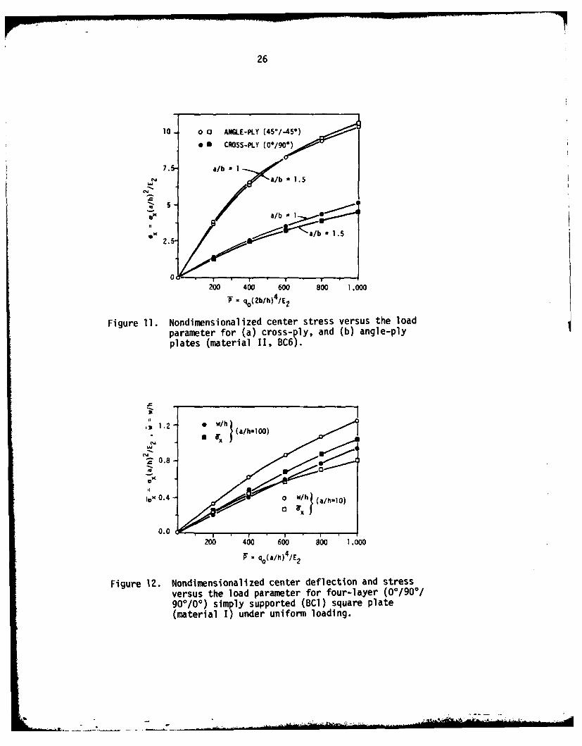
26
10- 0 0 ANGLE-PLY (45/-45*)
em11 CROSS-PLY (00/901)
7. a/b I
a/b 15
ex2 a/b - 1.5
200 400 600 800 1.000
T q 0(2b/h )4 /E2
Figure 11. Nondimensionalized center stress versus the loadparameter for (a) cross-ply, and (b) angle-plyplates (material II, BC6).
20.8-
ex
lox 0.4o / ah 0
0.0200 400 600 80o 1 .000
P=qo(a/h)4 /E2
Figure 12. Nondimensionalized center deflection and stressversus the load parameter for four-layer (00/900/90*/0*) simply supported (BCl) square plate(material 1) under uniform loading.
2.

27
-oi I -8(I: tCDko0 *
0C EOm
4-)4-
a, C)in n i CDm ml-l
CL
V) -0 -0 m c U*
L - -L L 0M n 9O
>) 0LA-(f
WO -) LO-z n0 -wM
4-) = - - -
(U)
cL 0C'4- .CC C DZ - o
ILL
( A J-'r - C) - C)J
eo C)mi CnM OD'E I
LULC Ma. 01) In A- 0
Oil 0 - - - -L - ~- - -.- 4-0
4aaU M
IC.-j
S-, COL ,6 C n'4- = -- -
0 4J-cfW (\J LA
aj o iiLnk .-C C %J 0LaO
4-C -*
LAJ 4- MC
.0tv
28
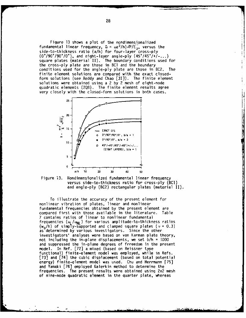
Figure 13 shows a plot of the nondimensionalizedfundamental linear frequency, I = wa2 /h)VPfE2, versus theside-to-thickness ratio (a/h) for four-layer cross-ply(0/901/900/0*), and eight-layer angle-ply (450/45*/+/-...)square plates (material II). The boundary conditions used forthe cross-ply plate are those in BC] and the boundaryconditions used for the angle-ply plate are those in BC2. Thefinite element solutions are compared with the exact closed-form solutions (see Reddy and Chao [31]). The finite elementsolutions were obtained using a 2 by 2 mesh of eight-nodequadratic elements (2Q8). The finite element results agreevery closely with the closed-form solutions in both cases.
25 K
20 -
00
I / / - EXACT CS0 o 0*/90°/90°/0c, b/a I 1
* 0°/90'/0' , b/a - 3
10 r10 :J, 45°!45°45°145/,/. ..
(EIGHT LAYERS), b/a - 1
0
a/h 10 20 30 40 50
Figure 13. Nondimenslonalized fundamental linear frequencyversus side-to-thickness ratio for cross-ply (BCI)and angle-ply (BC2) rectangular plates (material II).
To illustrate the accuracy of the present element fornonlinear vibration of plates, linear and nonlinearfundamental frequencies obtained by the present element arecompared first with those available in the literature. Table7 contains ratios of linear to nonlinear fundamentalfrequencies (w1 /wNL) for various amplitude-to-thickness ratios(w0/h) of simpTy-supported and clamped square plates (v = 0.3)as determined by various investigators. Since the otherinvestigators' analyses were based on von Karman plate theory,not including the in-plane displacements, we set b/h = 1000and suppressed the in-plane degrees of frreedom in the presentmodel. In Ref. [72] a mixed (based on Reissner typefunctional) finite-element model was employed, while in Refs.[73] and [74] the cubic displacement (based on total potentialenergy) finite-element model was used. Chu and Herrmann [75]and Yamaki [76] employed Galerkin method to determine thefrequencies. The present results were obtained using 2x2 meshof nine-node quadratic element in the quarter plate, whereas
-b .. ,

29
Table 7 Ratio of linear to nonlinear fundamentalfrequencies for various amplitude-to-thick-ness (c/h) ratios of simply-supported andclamped isotropic (v = 0.3), square plates.
frequency ratio ( _/NL)
Source 0.2 0.4 0.6 0.8 1.0[60I(2x2) 0.9818 0.9331 0.8671 0.7958 0.7271[72](4x4) 0.9818 0.9331 0.8670 0.7957 0.7270[73](4x4) 0.9818 0.9331 0.8670 0.7958 0.7271[74](5x5) 0.9821 0.9338 0.8673 0.7943 0.7233175]J 0.9809 0.9297 0.8702 0.9853 0.7131[771 0.9783 0.9210 0.8451 0.7653 0.6901
(2X2) 0.9929 0.9727 0.9419 0.9038 0.8616[72]
(4X4) 0.9930 0.9730 0.9425 0.9048 0.8631[73](4X4) 0.9930 0.9731 0.9427 0.9052 0.8637
74](5x5) 0.9930 0.9780 0.9550 0.9320 0.8960[751 0.9938 0.9750 0.9460 0.9116 0.8750[76] 0.9916 0.9716 0.9380 0.8980 07.56W
Table 8 Effect of side-to-thickness ratio (b/h) and edgeconditions on nonlinear frequencies of isotropic(v=0.3) square plates.
Boundary frequency ratio (wL/wNL)l ------Condition XLx10 s 0.2 0.4 0.6 0.8 TO-
ECIT 0.9499 0.9811 0.93080W6.-0 0.7904_709TEC2 2 0.9638 0.9818 0.9331 0.8671 0.7958 0.7271EC3 0.9499 0.9866 0.9494 0.8955 0.8333 0.7692EC4 0.9638 0.9871 0.9512 0.8990 0.8383 0.7754EC5 0.9499 0.9992 0.9927 0.9839 0.9720 0.9576ECl 2332.3 0.9804 0.9285 0.8591 0.7855 0.7155EC2 2388.0 0.9815 0.9324 0.8658 0.7942 0.7254EC3 2332.3 0.9862 0.9478 0.8925 0.8290 0.7639EC4 2388.0 0.9869 0.9506 0.8978 0.8366 0.7733EC5 2332.3 0.9992 0.9927 0.9838 0.9720 0.9576ECI 8944.1 0.9788 0.9232 0.8503 0.7745 0.7035EC2 9308.7 0.9808 0.9300 0.8620 0.7894 0.7203EC3 8944.1 0.9851 0.9440 0.8854 0.8152 0.8471EC4 9308.7 0.9864 0.9487 0.8943 0.8315 0.7669'convergence criteria, c = 10-2these aaree with those of Ref. r701, XL : ih/v'p-7

30
4x4 mesh of eight-node quadratic element was used in [72]. Itis clear that the present resutls are in excellent agreementwith the other approximate solutions.
Next the effect of boundary conditions and thickness onthe frequency ratio, wL/INL, is investigated, and the resultsare shown in Table 8. The boundary (or edqe) conditions usedin Table 8 are listed in Table 4, and are explained below:
ECl: Three (w, x )-degree of freedom model, with wspecified to e zero on the boundary (i.e., simply-supported edqes)-BC3(3DOF)
EC2: same as in BCl, except the tanqential rotations arealso specified to be zero on the boundary -BC4(3DOF)
EC3: Five (u,v,w,px,iv )-degree of freedom model with u,vand w specified o be zero on the boundary - BC3.
EC4: Five-degree of freedom model with the transversedeflection, in-plane displacements normal to theboundary, and tangential rotations are specified tobe zero at the boundary - BC2.
EC5: Five-degree of freedom model with only thetransverse deflection specified to be zero on theboundary.
As can be seen from the results, nonlinear frequenciesare more sensitive to the boundary conditions than linearfrequencies. This should he expected since the couplingbetween membrane and flexural stiffnesses is not present inthe linear theory. Restraining of the in-plane displacementsin effect stiffens the plate and conseuqently, the frequencyof vibration increases. Thus, for example, the (nonlinear)frequency of vibration of ECI (in which u and v are zeroeverywhere) is larger than that of EC3, although the linearfrequencies are identical. In EC5 in-plane displacements arenot restrained at all, and therefore thickness has nonoticeable effect on the frequency ratio; EC4 is a five-degreeof freedom version of EC2.
Figure 14 shows the plot of frequency ratio versus theamplitude-to-thickness ratio for various boundary conditionsand side-to-thickness ratio of isotropic (v = 0.3) squareplates. Since the plate stiffness is proportional to theplate thickness, and increases with edge constraints, thenonlinear frequencies are greater for thick plates than forthin plates.
Next, large-deflection free vibration of orthotropic andlayered composite plates is discussed. In Table 9, ratios oflinear to nonlinear fundamental frequencies are presented for

31
Table 9 Linear to nonlinear fundamental frequency ratio forvarious values of the amplitude-to-thickness ratiofor single-layer, and two-layer cross-ply squareplates under various boundary conditions (material:graphite-epoxy; AL = 'Lhr727)"
Boundary amplitude-to-thickness ratio (w0/h) LinearCondition 0.2 0.4 0.6 0.7 1.0 frequency
EC4(SL) i 0.9792 0.9227 0.8432 0.7555 0.6713 18.819EC4
(TL-CP)2 0.9801 0.9262 0.8510 0.7681 0.6865 16.096EC5
(TL-CP) 0.9990 0.9912 0.9805 0.9663 0.9490 11.122EC6
(TL-CP) 0.9990 0.9912 0.9806 0.9664 0.9491 11.173EC4
(SL) 0.9643 0.8736 0.7611 0.6523 0.5581 14.118EC4
(TL-CP) 0.9775 0.9174 0.8354 0.7478 0.6649 13.956EC6
(TL-CP) 0.9976 0.9907 0.9797 0.9651 0.9478 10.300
'SL = Single-layer2TL-CP = Two-Layer, Cross-Ply
0.9.
0.8 "0 clamped (b/h - 1000)
-4-claped (b/h - 5)
BC3 (b/h - 1000)
0.7- & BC1 (b/h - 1000)
BC1 (b/h - 5)
v /h 0.2 o.. 0.6 0.8 1.00
Figure 14. Ratio of linear to nonlinear fundamental frequencies(y = WL/JL) versus the amplitude-to-thickness ratio(w /h) fo isotropic (v = 0.3) square plates (in-planedeorees of freedom not included).

32
3U-
25" -. 8
kL(45'/45*)
2a. .75
5 (0/9 -
(0.. /90. 7
L !, b 12 1. 32
Figure 15. Effect of orthotropy (GlIE = 0.3846, v = 0 3)on the linear nondimensinaiized fundamehal fre-quency (A) and on the ratio (w = w 1w ) of linearto nonlinear fundamental frequencies h' squareplates (b/h = 10).
single-layer orthotropic and two-layer cross-ply square platesunder various boundary conditions. The material propertiesused are those of graphite-epoxy material (G1 =G 23 = G1f),material II, and the edge conditions EC6 are aescribed be ow:
EC6: same as EC4, except no in-plane displacements arespecified on the boundary (or same as EC5, exceptthe tangential rotations are also specified on theboundary).
Couple of observations can be made from the results presentedin Table 9. First, there is no difference in the frequenciesobtained by EC5 and EC6. In other words, specification of thetangential rotations does not alter the vibration frequenciesappreciably. As one might suspect, the frequencies obtainedby EC4 and EC5 are noticeably different; the nonlinearfundamental frequencies of EC4 are much larger than those ofEC5 and EC6. Second, there is a reduction of about 38% infrequencies from single-layer to two-layer (for the same totalthickness) plates.
Figure 15 shows the effect of orthotropy (E,/E2 for fixedG12/E2 =.0.3846, v12 = 0.3) on the linear fundamentalfrequencies and on the ratio of linear to nonlinearfrequencies of single-layer and two-layer cross-ply squareplates (b/h = 10) subjected to boundary condition EC4. While
-b

33
-1h - 1000
0-sigle-laer,
" - 10 two-laver, clamped
b/h - 1000, BC6
- 0.2 .. 0.6 0.8 1.0
I'I
(a) Cross-ply plates tO*/90*)
i ,--0- b/h 1000(BC4)
"--b/h - 10
0.6
[ I I . I I
__ 0.2 0.4 0.6 0.8 1.0h
(b) Angle-ply plates (45°/-45*)
Figure 16. Ratio of linear to nonlinear fundamental frequenciesversus amplitude to thickness ratio of single-layerand two-layer square plates (EI/E 2 = 40, G12/E2 0.5,V12 = 0.25).

34
the linear frequencies increase, the ratio of linear tononlinear frequencies decreases with increasing E,/EAlthouqh the linear fundamental frequency of the angfe-plyplate is larger than the cross-ply plate, the ratio wL/wNL issmaller for anqle-ply plate than for the cross-ply plate.This indicates that the nonlinearity is more pronounced in theangle-ply plate than in the cross-ply plate.
Lastly, Figure 16 shows plots of linear to nonlinearfrequencies versus the amplitude-to-thickness ratio for two-layer clamped (transverse deflection and the normal rotationare set to zero on the boundary-BC8) square plates ofgraphite-epoxy material; plots for thin (b/h = 1000) and thick(b/h = 10), cross-ply as well as angle-ply plates are shown inFig. 16.
7. SUMMARY AND CONCLUSIONS
A finite element based on a shear deformable theory (see[14]) and von Karman (larqe rotations) theory of layeredcomposite plates is reviewed and numerical results for staticbending and free vibrations are presented for isotropic,orthotropic, and layered composite plates of rectanqulargeometry. It is noted that the nonlinearity is lesspronounced in the layered composite plates than in theisotropic plates.
From the study it can be concluded that the four-node andnine-node isoparametric elements (with reduced integration forshear enerqy terms) give accurate results while possessinqsimplicity over traditional plate elements. As pointed outearlier (also, see [79-81]), the element can be viewed as onebased on a penalty function formulation of classical thinplate theory with the slope continuity conditions asconstraints. The penalty terms (i.e., shear energy terms) inthe stiffness matrix must be evaluated using reducedinteqration in order to avoid so-called locking (i.e., toavoid excessively stiff elements; see [82]). An extension ofthe penalty-function method to enforce the inter-element slopecontinuity needs further investigation (see Haugeneder [83]).A study of the mathematical properties (e.g., stability, errorestimates, etc.) of the plate bendinq element presented hereinis not complete (see, Ohtake, Oden, and Kikuchi [84,85] forsome preliminary results).
Although the shear deformable theory of layered compositeplates presented here yields acceptable solutions for globalresponse of the plate, locally (i.e., point-wise) the theorydoes not predict stresses accurately. The questions relatingto interlaminar stresses, edge effects, and delamination incomposites (see [86-951) can be addressed only when a higherorder, three-dimensional theory is employed (see [96-1001).The comments made above also apply to the case of laminated

35
composite shells. Thus, developments in computationalmechanics related to finite-element analysis of plates andshells in the next decade would largely concern with thedevelopment of computationally simple elements that arecapable of representing accurately physical features of thephenomena involved.
ACKNOWLEDGMENTS
The results presented in the paper were obtained duringinvestigations supported by Structures Mechanics Programs ofthe Office of Naval Research (N00014-78-C-0647), and the AirForce Office of Scientific Research (Grant AFSOR-81-0142).The support is gratefully acknowledged. It is also a pleasureto acknowledge the skillful typing of the manuscript by Mrs.Vanessa McCoy.
REERENCES
1. STAVSKY, Y. - On the Theory of SymmetricallyHeterogeneous Plates Havinq the Same Thickness Variationof the Elastic Moduli. Topics in Applied Mechanics, Ed.Abir, D., Ollendorff, F. and Reiner, M., AmericanElsevier, New York, 1965.
2. YANG, P. C., NORRIS, C. H. and STAVSKY, Y. - Elastic WavePropagation in Heterogeneous Plates. Int. J. Solids andStructures, Vol. 2, pp. 665-684, 1966.
3. SUN, C. T. and WHITNEY, J. M. - Theories for the DynamicResponse of Laminated Plates. AIAA J., Vol. 11, pp. 178-183, 1973.
4. WHITNEY, J. M. and SUN, C. T. - A Higher Order Theory forExtensional Motion of Laminated Composites. J. Sound andVibration, Vol. 30, pp. 85-97, 1973.
5. SRINIVAS, S. and RAO, A. K. - Bending, Vibration andBuckling of Simply Supported Thick OrthotropicRectangular Plates and Laminates. Int. J. Solids andStructures, Vol. 6, pp. 1463-1481, 1970.
6. SRINIVAS, S., JOGA RAO, C. V. and RAO, A. K. - An ExactAnalysis for Vibration of Simply Supported Homogeneousand Laminated Thick Rectangular Plates, J. Sound andVibration, Vol. 12, pp. 187-199, 1970.
7. HUSSAINY, S. A. and SRINIVAS, S. - Flexure of RectanqularComposite Plates. Fibre Science and Technology, Vol. 8,pp. 59-76, 1975.

36
8. BERT, C. W. - Analysis of Plates. Structural Design andAnalysis, Part I, Ed. Chamis, C. C., Academic Press, NewYork, 1974.
9. PAGANO, N. J. - Exact Solutions for Composite Laminatesin Cylindrical Bending. J. of Composite Materials, Vol.3, No. 3, pp. 398-411, 1969.
10. PAGANO, N. J. - Exact Solutions for RectangularBidirectional Composites and Sandwich Plates. J. ofComposite Materials, Vol. 4, pp. 20-34, 1970.
11. PAGANO, N. J. and HATFIELD, S. J. - Elastic Behavior ofMultilayer Bidirectional Composites. AIAA Journal, Vol.10, pp. 931-933, 1972.
12. WHITNEY, J. M. - The Effect of Transverse ShearDeformation on the Bending of Laminated Plates. J.Composite Materials, Vol. 3, No. 3, pp. 534-547, T969.
13. MAU, S. T. - A Refined Laminated Plate Theory. J. Appl.Mech., Vol. 40, pp. 606-607, 1973.
14. WHITNEY, J. M. and PAGANO, N. J. - Shear Deformation inHeterogeneous Anisotropic Plates. J. Appl. Mech., Vol.37, pp. 1031-1036, 1970.
15. FORTIER, R. C. and ROSSETTOS, J. N. - On the Vibration ofShear Deformable Curved Anisotropic Composite Plates.J. Appl. Mech., Vol. 40, pp. 299-301, 1973.
16. SINHA, P. K. and RATH, A. K. - Vibration -Ind Buckling ofCross-Ply Laminated Circular Cylindrical Panels.Aeronautical Quarterly, Vol. 26, pp. 211-218, 1975.
17. BERT, C. W. and CHEN, T. L. C. - Effect of ShearDeformation on Vibration of Antisyminetric Angle-PlyLaminated Rectangular Plates. Int. J. Solids andStructures, Vol. 14, pp. 465-473, 1978.
18. PRYOR, JR., C. W. and BARKER, R. M. - A Finite ElementAnalysis Including Transverse Shear Effects forApplications to Laminated Plates. AIAA J., Vol. 9, pp.912-917, 1971.
19. BARKER, R. M., LIN. F. T. and DANA, J. R. - Three-Dimensional Finite-Element Analysis of LaminatedComposites. National Symposium on ComputerizedStructural Analysis and Desiqn, Georqe WashinqtonUniversity, 1972.
37
20. MAU, S. T., TONG, P. and PIAN, T. H. H. Finite ElementSolutions for Laminated Thick Plates. J. CompositeMaterials, Vol. 6, pp. 304-311, 1972.
21. MAU, S. T. and WITMER, E. A. - Static, Vibration, andThermal Stress Analyses of Laminated Plates and Shells bythe Hybrid-Stress Finite Element Method with TransverseShear Deformation Effects Included. Aeroelastic andStructures Research Laboratory, Report ASRL TR 169-2,Department of Aeronautics and Astronautics, MIT,Cambridge, MA, 1972.
22. NOOR, A. K. and MATHERS, M. D. - Anisotropy and ShearDeformation in Laminated Composite Plates. AIAA J., Vol.14, pp. 282-285, 1976.
23. NOOR, A. K. and MATHERS, M. D. - Finite Element Analysisof Anisotropic Plates. Int. J. Num. Meth. Enqng., Vol.11, pp. 289-307, 1977.
24. HINTON, E. - A Note on a Thick Finite Strip Method forthe Free Vibration of Laminated Plates. Earthquake Eng.and Struct. Dynamics., Vol. 4, pp. 511-514, 1976.
25. HINTON, E. - Flexure of Composite Laminates Using theThick Finite Strip Method. Computers and Structures, Vol.7, pp. 217-220, 1977.
26. MAWENYA, A. S. and DAVIES, J. D. - Finite Element BendinAnalysis of Multilayer Plates. Int. J. Num. Meth.Engng., Vol. 8, pp. 215-225, 1974.
27. PANDA, S. C. and NATARAJAN, R. - Finite Element Analysisof Laminated Composite Plates. Int. J. Num. Meth.Engng., Vol. 14, pp. 69-79, 1979.
28. AHMAD, S., IRONS, B. M. and ZIENKIEWICZ, 0. C. - Analysisof Thick and Thin Shell Structures by Curved FiniteElements. Int. J. Num. Meth. Engng., Vol. 2, pp. 419-451, 1970.
29. SPILKER, R. L., CHOU, S. C. and ORRINGER, 0. - AlternateHybrid Stress Elements for Anslysis of MultilayerComposite Plates. J. Composite Materials, Vol. 11, pp.51-70, 1977.
30. REDDY, J. N. - A Penalty Plate-Bendinq Element for theAnalysis of Laminated Anisotropic Composite Plates. Int.J. Numer. Meth. Engng., Vol. 15, pp. 1187-1206, 1980.'

31. REDDY, J. N. and CHAO, W. C. - A Comparison of Closed-Form and Finite Element Solutions of Thick LaminatedAnisotropic Rectangular Plates. Nuclear Enqineering andDesign, Vol. 64, 1981, to appear.
32. REDDY, J. N. - Free Vibration of Antisymmetric, Angle-PlyLaminated Plates, Including Transverse Shear Deformationby the Finite Element Method. J. Sound and Vibration,Vol. 66, No. 4, pp. 565-576, 1979.
33. REDDY, J. N. and BERT, C. W. - Analyses of PlatesConstructed of Fiber-Reinforced Bimodulus Materials.Mechanics of Bimodulus Materials, Ed. Bert, C. W., AMDVol. 33, American Society of Mechanical Engineers, NewYork, pp. 29-37, 1979.
34. REDDY, J. N. and CHAO, W. C. - Finite-element Analysis ofLaminated Bimodulus Composite-Material Plates. Computersand Structures, Vol. 12, pp. 245-251, 1980.
35. WHITNEY, J. M. and LEISSA, A. W. - Analysis ofHeterogeneous Anisotropic Plates. J. AppI. Mech., Vol.36, pp. 261-266, 1969.
36. BENNETT, J. A. - Nonlinear Vibration of Simply SupportedAngle Ply Laminated Plates. AIAA J., Vol. 9, pp. 1997-2003, 1971.
37. BERT, C. W. - Nonlinear Vibration of a Rectangular PlateArbitrarily Laminated of Anisotropic Material. J. Appl.Mech., Vol. 40, pp. 452-458, 1973.
38. CHANDRA, R. and RAJU, B. B. - Large Amplitude FlexuralVibration of Cross Ply Laminated Composite Plates. FibreScience and Technology, Vol. 8, pp. 243-263, 1975.
39. CHANDRA, R. - Large Deflection Vibration of Cross-PlyLaminated Plates with Certain Edge Conditions. J. Soundand Vibration, Vol. 47, No. 4, pp. 509-514, 1976.
40. ZAGHLOUL, S. A. and KENNEDY, J. B. - Nonlinear Analysisof Unsymmetrically Laminated Plates. J. Engng. Mech.Div., ASCE, Vol. 101 (EM3), pp. 169-185, 1975.
41. CHIA, C. Y. and PRABHAKARA, M. K. - Large Deflection ofUnsymmetric Cross-Ply and Angle-Ply Plates. J. Mech.Engng. Sci., Vol. 18, No. 4, pp. 179-183, 197.
42. CHIA, C. Y. and PRABHAKARA, M. K., - A General ModeApproach to Nonlinear Flexural Vibrations of LaminatedRectangular Plates. J. Appl. Mech., Vol. 45, pp. 623-628, 1978.

39
43. NOOR, A. K. and HARTLEY, S. J. - Effect of ShearDeformation and Anisotropy on the Non-Linear Response ofComposite Plates. Developments in Composite Materials -1, Ed. Holister, G., Applied Science Publishers, Barking,Essex, England, pp. 55-65, 1977.
44. REDDY, J. N. and CHAO, W. C. - Large Deflection and LargeAmplitude Free Vibrations of Laminated Composite MaterialPlates. Computed Structures, Vol. 13, No. 2, pp. 341-347, 1981.
45. REDDY, J. N. and CHAO, W. C. - Non-Linear Bending ofThick Rectangular, Laminated Composite Plates. Int. J.Non-Linear Mechanics, 1981, to appear.
46. AMBARTSUMYAN, S. A. - Theory of Anisotropic Plates(English Translation), Technomic, Stamford, Conn., 1970.
47. HASSERT, J. E. and NOWINSKI, J. L. - Nonlinear TransverseVibration of a Flat Rectangular Orthotropic PlateSupported by Stiff Rig. Proc. of 5th InternationalSymposium on Space Technology and Science, Tokyo, pp.561-570, 1962.
48. NOWINSKI, J. L. - Nonlinear Vibrations of ElasticCircular Plates Exhibiting Rectilinear Orthotropy.Zeitschrift fur Angew Methematik and Physik, Vol. 14, pp.112-124, 1963.
49. NOWINSKI, J. L. and ISMAIL, I. A. - Large Oscillations ofan Anisotropic Triangular Plate. J. of the FranklinInstitute, Vol. 280, pp. 417-424, 1965.
50. WU, C. I. and VINSON, J. R. - On the NonlinearOscillations of Plates Composed of Composite Materials.J. of Composite Materials, Vol. 3, pp. 548-561, 1969.
51. MAYBERRY, B. L. and BERT, C. W. - ExperimentalInvestigation of Nonlinear Vibrations of LaminatedAnisotropic Panels. Shock and Vibration Bulletin, Vol.39, Part 3, pp. 191-199, 1969.
52. NOWINSKI, J. L. - Nonlinear Oscillations of AnisotropicPlates Under Large Initial Stress. Proc. of the 10thCongress of Theoretical and Applied Mechanics, Madras,India, pp. 13-30, 1965.
53. SATHYAMOORTHY, M. and PANDALAI, K. A. - NonlinearFlexural Vibrations of Orthotropic Rectanqular Plates.J. of Aeronautical Society of India, Vol. 22, pp. 264-
... .... -_,___ ,_____ nln_______u__1

40
54. PRABHAKARA, M. K. and CHIA, C. Y. - Nonlinear FlexuralVibrations of Orthotropic Rectangular Plates. J. ofSound and Vibration, Vol. 52, pp. 511-518, 1977.
55. SATHYAMOORTHY, M. and CHIA, C. Y. - Non-Linear Vibrationof Anisotropic Rectangular Plates Including Shear andRotatory Inertia. Fibre Science and Technology, Vol. 13,pp. 337-361, 1980.
56. SATHYAMOORTHY, M. and CHIA, C. Y. - Effect of TransverseShear and Rotatory Inertia on Large Amplitude Vibrationof Anisotropic Skew Plates, Part 1 - Theory. J. Appl.Mech., Vol. 47, pp. 128-132, 1980.
57. SATHYAMOORTHY, M. and CHIA, C. Y. - Effect of TransverseShear and Rotatory Inertia on Large Amplitude Vibrationof Anisotropic Skew Plates, Part 2 - Numerical Results.J. Appl. Mech., Vol. 47, pp. 133-138, 1980.
58. WU, C. I. and VINSON, J. R. - Nonlinear Oscillations ofLaminated Specially Orthotropic Plates with Clamped andSimply Supported Edges. Journal of the AcousticalSociety of America, Vol. 49, pp. 1561-1567, 1971.
59. CHANDRA, R. and BASAVA RAJU, B. - Large DeflectionVibration of Angle Ply Laminated Plates. Journal ofSound and Vibration, Vol. 40, pp. 393-408, 1975.
60. REDDY, J. N. - Nonlinear Vibration of Layered CompositePlates Including Transverse Shear and Rotatory Inertia.1981 ASME Vibration Conference, Hartford, Connecticut,September 20-23, 1981.
61. REDDY, J. N. - Simple Finite Elements with RelaxedContinuity for Nonlinear Analysis of Plates. Proc. ThirdInt. Conf. in Australia on Finite Element Methods,University of New South Wales, Sydney, July 2-6, 1979.
62. ZIENKIEWICZ, 0. C., TAYLOR, R. L. and TOO, J. M. -Reduced Integration Technique in General Analysis ofPlates and Shells. Int. J. Num. Meth. Engng., Vol. 3,pp. 575-586, 1971.
63. HUGHES, T. J. R., COHEN, M. and HAROUN, M. - Reduced andSelective Integration Techniques in the Finite ElementAnalysis of Plates. Nuclear Engineering and DesLqn, Vol.46, pp. 203-222, 1978.
64. WHITNEY, J. M. - Stress Analysis of Thick LaminatedComposite and Sandwich Plates. J. Composite Materials,Vol. 6, pp. 426-440, 1972.

41
65. WAY, S. Uniformly Loaded, Clamped, Rectangular Plateswith Large Deformation. Proc. 5th Int. Congr. Appl.Mech. (Cambridqe, Mass., 1938), John Wiley, pp. 123-238,
66. LEVY, S. - Bending of Rectangular Plates with LargeDeflections. Report No. 737, NACA, 1942.
67. WANG, C. T. - Bendinq of Rectangular Plates with LargeDeflections. Report No. 1462, NACA, 1948.
68. YAMAKI, N. - Influence of Large Amplitudes on FlexuralVibrations of Elastic Plates. ZAMM, Vol. 41, pp. 501-510, 1967.
69. KAWAI, T. and YOSHIMURA, N. - Analysis of LargeDeflection of Plates by the Finite Element Method. Int.J. Numer. Meth. Enqng., Vol. 1, pp. 123-133, 1969.
70. PICA, A., WOOD, R. 0. and HINTON, E. - Finite ElementAnalysis of Geometrically Nonlinear Plate Behavior Usinga Mindlin Formulation. Computers & Structures, Vol. 11,pp. 203-215, 1980.
71. LEVY, S. - Square Plate with Clamped Edges Under PressureProducing Large Deflections. NACA, Tech. Note 847, 1942.
72. REDDY, J. N. and STRICKLIN, J. D. - Larqe Deflection andLarge Amplitude Free Vibrations of Thin RectangularPlates Using Mixed Isoparametric Elements. Applicationsof Computer Methods in Engineering, Vol. II7d.Wellford, Jr., L. C., University of Southern California,Los Angeles, pp. 1323-1335, 1977.
73. RAO, G. V., RAJU, I. S., KANAKA RAJU, K. - A FiniteElement Formulation for Large Amplitude FlexuralVibrations of Thin Rectangular Plates. Computers &Structures, Vol. 6, pp. 163-167, 1976.
74. MEI, C. - Finite Element Displacement Method for LargeAmplitude Free Flexural Vibrations of Beams and Plates.Computers & Structures, Vol. 3, pp. 163-174, 1973.
75. CHU, H. N. and HERRMANN, G. - Influence of LargeAmplitudes on Free Flexural Vibrations of RectangularElastic Plates. J. of Applied Mechanics, Vol. 23, pp.532-540, 1956.
76. YAMAKI, N. - Influence of Large Amplitudes on FlexuralVibrations of Elastic Plates. ZAMM, Vol. 41, pp. 501-510, 1967.
42
77. WAH, T. - Large Amplitude Flexural Vibration ofRectangular Plates. Int. J. Mech. Sci., Vol. 5, pp.425-438, 1963.
78. KANAKA RAJU, K. and HINTON, E. - Nonlinear Vibrations ofThick Plates Using Mindlin Plate Elements. Int. J.Numer. Meth. Enqnq., Vol. 15, pp. 249-257, 1980.
79. WESTBROOK, D. R., CHAKRABARTI, S. and CHEUNG, Y. K. - AThree-Dimensional Finite Element Method for PlateBending. Int. J. Mech. Sci., Vol. 16, pp. 479-487, 1974.
80. WESTBROOK, D. R., CHAKRABARTI, S. and CHEUNG, Y. K. - AThree-Dimensional or Penalty Finite Element Method forPlate Bending. Int. J. Mech. Sci., Vol. 18, pp. 347-350,1976.
81. HUGHES, T. J. R., TAYLOR, R. L. and KANOKNUKULCHAI, W. -A Simple and Efficient Finite Element for Plate Bending.Int. J. Numer. Meth. Engng., Vol. 11, pp. 152g-1543,1977.
82. ZIENKIEWICZ, 0. C. and HINTON, E. - Reduced Integration,Function Smoothing and Non-Conformity in Finite ElementAnalysis. J. Franklin Inst., Vol. 302, pp. 443-461,1976.
83. HAUGENEDER, E. - A New Penalty Function Element for ThinShell Analysis. Seventeenth Annual Meeting of theSociety of Engineering Science, Georgia Institute ofTechnology, Atlanta, GA, December 15-17, 1980.
84. OHTAKE, 0., ODEN, J. T. and KIKUCHI, N. - Analysis ofCertain Unilateral Problems in von Karman Plate Theory bya Penalty Method - Part 1. A Variational Principle withPenalty. Comp. Meth. in Appl. Mech. Enqng., Vol. 24, pp.187-213, 199-0.
85. OHTAKE, 0., ODEN, J. T. and KIKUCHI, N. - Analysis ofCertain Unilateral Problems in von Karman Plate Theory bya Penalty Method - Part 2. Approximation and NumericalAnalysis. Comp. Meth. in Appl. Mech. Enng., Vol. 24,pp. 317-337, 1980.
86. HAYASHI, T. - Analytical Study of Interlaminar ShearStresses in a Laminated Composite Plate. Trans. JapanSoc. Aero. Engng. Space Sciences, Vol. 10, No. 47, p. 43,1967.
87. PAGANO, N. J. - Stress Fields in Composite Laminates.Int. J. Solids Structures, Vol. 14, pp. 385-400, 1978.
43
88. PAGANO, N. J. - Free Edge Stress Fields in CompositeLaminates. Int. J. Solids Structures, Vol. 14, pp. 401-406, 1978.
89. WANG, A. S. D. and CROSSMAN, F. W. - Some New Results onEdge Effect in Symmetric Composite Laminates. J.Composite Materials, Vol. 8, pp. 92-106, 1977.
90. SALAMON, N. J. - Interlaminar Stresses in a LayeredComposite Laminate in Bending. Fibre Science andTechnology, Vol. 11, pp. 305-317, 1978.
91. WANG, S. S. and CHOI, I. - Boundary Layer ThermalStresses in Angle-Ply Composite Laminates. ModernDevelopments in Composite Materials and Structures, Ed.Vinson, J. R., American Society of Mechanical Engineers,New York, pp. 315-341, 1979.
92. WANG, S. S. - Edge Delamination in Angle-Ply CompositeLaminates. Proc. 22nd AIAA/ASME/SAE Structures,Structural Dynamics, and Materials Conference, Atlanta,GA, pp. 473-484, 1981.
93. SPILKER, R. L. and CHOU, S. C. - Edge Effects inSymmetric Composite Laminates: Importance of Satisfyingthe Traction-Free-Edge Condition. J. CompositeMaterials, Vol. 14, pp. 2-20, 1980.
94. RAJU, I. S. and CREWS, Jr., J. H. - Interlaminar StressSingularities at a Straight Free Edge in CompositeLaminates. NASA Technical Memorandum 81876, LanqleyResearch Center, Hampton, VA, 1980.
95. RAJU, I. S., WHITCOMB, J. D. and GOREE, J. G. - A NewLook at Numerical Analyses of Free-Edge Stresses inComposite Laminates. NASA Technical Paper 1751, LanqleyResearch Center, Hampton, VA 1980.
96. WHITNEY, J. M. and SUN, C. T. - A Refined Theory forLaminated Anisotropic, Cylindrical Shells. J. Appl.Mech., Vol. , pp. 471-476, 1974.
97. LO, K. H., CHRISTENSEN, R. M. and WU, E. M. - A Higher-Order Theory of Plate Deformation, Part 1: HomogeneousPlates. J. Appl. Mech., Vol. 44, pp. 662-668, 1977.
98. LO, K. H., CHRISTENSEN, R. M. and WU, E. M. - A Higher-Order Theory of Plate Deformation, Part 2: LaminatedPlates. J. App1. Mech., Vol. 44, pp. 669-676, 1977.
99. SPILKER, R. L. - Higher Order Three-Dimensional Hybrid-Stress Elements for Thick-Plate Analyses. Int. J.Numer. Meth. Engng, Vol. 17, pp. 53-69, l981.
4J

44
100. ALTUS, E., ROTEM, A. and SHMUELI, M. - Free Edqe Effectin Anqle Ply Laminates - A New Three Dimensional FiniteDifference Solution. J. Composite Materials, Vol. 14,pp. 21-30, 1980.
APPENDIX A: NOMENCLATURE
Aij,Bij,Dij extensional, flexural-extensional andflexural stiffnesses (ij = 1,2,6).
a,b plate planform dimensions in x,ydirections, respectively
EIE 2 layer elastic :noduli in directionsalong fibers and normal to them,respectively
CnCmCq boundary segments of domain R
G12,G3,G layer in-plane and thickness shearmoduli
hhi total thickness of the plate; thicknessof i-th layer
rotatory inertia coefficient per unitmidplane area of lamina
ki shear correction coefficientsassociated with the yz and xz planes,respectively (i = 1,2)
K4 element stiffness coefficients (cf13 1,2,...,5; ij = 1,2,...,n)
L total number of layers in the plate
Mi ,Ni stress couple and stress resultant,respectively (i = 1,2,6)
MO element mass coefficients (c,81,2,...,5; i,j = 1,2,...,n)
n number of nodes per element
P laminate normal inertia coefficient perunit midplane area
Qi shear stress resultant (i = 1,2)
Qij plane-stress reduced stiffnesscoefficients (ij = 1,2,6)

45
qo intensity of transversely distributedload
R laminate rotatory-normal couplinqinertia coefficient per unit midplanearea
R; Re domain (midplane of the plate); typicalelement
R nCS 9 element matrices in FEM formulationI0 13 = 0, x,y; i,j = 1,2,. ..,n)
t time
UIU 2,U3 displacement components in x,y,zdirections, respectively
u,v in-plane displacements in x,ydirections
U,Ui, etc. typical variable and its nodal value,respectively
x,y,z position coordinates in cartesiansystem
{A} column if vector of qeneralized nodaldisplacements
strain components (i = 1,2,...,6)
em orientation of m-th layer (m =1,2,...,L)
p(m) density of m-th layer (m = 1,2,...,L)
A nondimensional fundamental frequency
Oi stress components (i = 1,2,...,6)
finite-element interpolation functions(i = 1.2,...,n)
xqey bending slope (rotation) functions
Ki plate curvatures (i = 1,2,6)
wfundamental frequency of free vibration(at = linear; wNL = nonlinear)

46
APPENDIX B: ELEMENTS OF STIFFNESS AND MASS MATRICES
stiffness matrix:
2( 1 ] 2 x 2 2K1 [ 4 pK1
T[K 21] [K22] A2[1(23] uPjK 24 ip[K 25]K]=A[ 31] 32 3 34 ~ [135]
(K TKIA[ [K1 I i[K 1 1[K3 ~ ~ 3 3335A (4
+A [K32 PAK] +iiA[K 241 42] 43 44 4
T[K] T [ A[K1 p[K ] iK 45
+2 IK43
51 52 53 54(54]T[K I T[K ] N[K I p[KK 55]
2 53
mass matrix:
P[S] [0] [0] R[S] [0]
[0] P[S] [0] [0] R[S]
[M] 1 0] [0] P[sj to] [0]
R[S] [0] [0] I[S] [0]
[0] R[S] [0] [01 ILS]
The matrix coefficients K" are given by13
[K11]1 = Aj1[Sxx] + A1 [SY + [YT) +A
[K] = A 12[Sxy]+A [51XX] + A 26SYY] + A 21Txl K
[K(13] = A,[Rxx] + A ERXY] + A([Rxy] + CRXY] T + [Rxx])ix 12 y 16x x y
+ A26[Ryy] + A 6 [Rxy] T + [RYY]) - K ~ 31]T,
[K 14] = B11[Sxx] + B 16([SXYI+[Sxy] T) + B661Syy] = [1(41]T,
[11 = B 2[Sxy]+Bl6([Sxy] + B26[Syy] + B66 1Sxy] T [K [51]T
[K(22] = A22[Sy + A 26([Sxy] T + [Sxy]) + A 66[Sxx],
y-ILL 11I
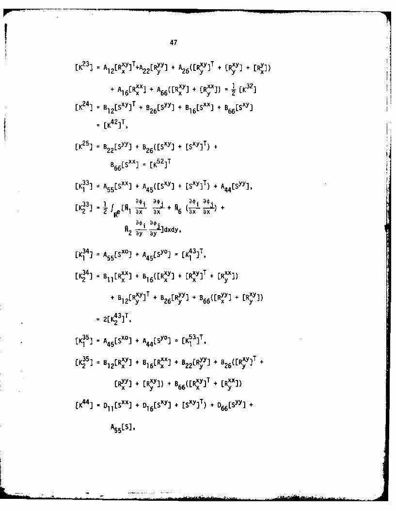
47
[K23) A A[Rxy]T+A22[R~y] + A 6 [Rj7]T + [Rxy] + [Ryx])
+'jL\ A6~x y )=-[ A Rxyl + £RXX]) 1 [K32j
[K24 1 B12[S"3 ]' + B26[Syy] + B 16[SXX] + B 66ESXY] -
I K42 IT
[K 25] B = Sy + B 26([Sxy] + [SXY] T) +
33 B66[Sxx] = K51TT
[K 1 ] = A 55[SXX] + A 45([Sxy] + [SxY]T + A4[y]
[K 33] = .~ 1 f ~ 2 -D i j+N Doi-a +2 2 1ax ax 6 ax ax)
aJl.xdy.2 ay ay
[K I I = A 55 [Sxo) + A4[yj= [
[K 34 = B11[R~x] + B 6 [Rxy) + [RXY]T + ERXX])
+ IB1 [RxY]T + B26[Ryy] + B66([Ryy] + [Rxy])
[K, I = A 45[S xO] + A 44 [Sy0) = [Ki IT
35J = [RxyJ + 816(R~x] + B Ry + B ([RxyJ T +
[Ryy) +g [RXyI1) + B,,(ERXY)T + [RXX)x yJ 66 x y
EK14) Dl1[Sxx) + D 16[SXY] + (SxY) T) + D66[Syy] +
A 55 [S),

48
[K45 D D[SXY] + D16[Sxx) + D26[Syy] + D66[SXY]T +
+ A45 [S] = [K54]T,
[K 55] D D26(LSxy] +~ [S"X" T + D 66[Sxx] + D22[Syy] +
and + A44[S].
S.. = f '. "a dxdy . C,ri = O,x,y, So S.
Rtn= 2 (a') ,a~~ dxdy. g = O~x,y,
1=All (2-w)2 + A 2 ( .2 + 2A16awaw,
2 12 ax(+WA 2 2 26 axD
A _w)2+A 2+ 2A awawN6 = 16 ax~ + 26 (-ayw) +2 66 ax ay
SECUMiTY CLASSIFICATION OF THIS PAGE (35.., Dot Enler.4_________________
REPORT DOCUMENTATION PAGE ________COPLET__GFORM
I. RVPORT NUMall 11. 337F ACCESSION NO: 3- RIECIPIENT'S CATAI-OG NUMNIER
VPI-E-81 -12 AD]- 9f A 9J3 R
FOR 'ARGE OF .AYERED OMPOSITE PLATES ACCOUNTING i-_ORNS.. DE LECTIONS'AND TRANSVERSE SHEAR Ineim rep
STY NS - . PERFORMING ~.omtOT NUM8ER_____________________________________ Tech. Report No. 21
7. AUTWOReC) S. CONTRACT ON GRANT NUM1111R(a)
( jJ. N./Reddy 7/5 N~46,1 78C 64
S. PERFORMING ORGANIZATION NAME AND ADDRESSI 4rPVXWLMTPRJCAS
Virginia Polytechnic Institute and StateARA RKNTNUES
Blackburg VA 4061NR064-609
Department of the Navy, Office of Naval Rese jMay 381Structural Mechanics Program (Code 474) '13. NUMbER OP PAGES
14. MONITORING AGENCY NAMIE & AOORESS(iI different from, Ccentomlng Office) IS. SECURITY CLASS. (of tis. r~'pa~)
Unclassified5- tSe. 04ECLASSI FICATION/ DOWNGRADINGSCHEDULE
T6. GI1STRIBUTION SiTEt MIS As enf)
This document has been approved for public release and sale; distributionunlimited
17. OISTRIOUTION STATEMENT (at the abotract eered Ing Stock 20. It different howu R~~q)
.Auri'MAN "N' report will appear as an ASME paper to be presented at the1981 ASME Vibration Conference, in Hartford, Connecticut during September 15-20, 1981. The paper will appear in its entirity in "Recent Advances in Non-linear Computational Mechanics," Hinton et al. (eds.), Pine Ridge Press, Swansea,
III. 'lRay"PRO&I eba 4Jm %"we aom"ide it noeeem Oid H eb b leeoombrangle-ply, composite materials, cross-ply, fiber-reinforced materials, finiteelement method, free vibration, laminates, large deflections, natural fre-quencies, nonlinear frequencies, plate bending, rectangular plates, rotatoryinertia, transverse shear deformation.
20. ASSTRACT (Contiuue an aoeree 01,i DII O OeWNea aid n.I6V apbleonmbr
I" :A finite-element analysis is presented for large-deflection bending and larg~eamplitude free vibration of rectangular plates of cross-ply and angle-ply con-struction under various edge conditions and loadings. The finite elementemployed in the present study accounts for transverse sheaWi and rotatory inert a(in the Reissner-Mindlin sense), and large rotations (in the von Karman sense)The finite element solutions are found to agree very closely with resultsavailable in the literature.
DD I 1473'.., 90 MOPIMOVIISISONSOLE~TI UNCLASSIFIED Q (S/N @02014 ISCUONTY CLASUPICATION OF T"16 PAGS (Whn Dole 804041

~CU~YCLASSIFICATION OF THIS PAGIE(Whi og. "AogmdW
StCUMITY CLASSIFICATIONI OF THIS PA~gd'W,. D.e EnaeE