MFFR Data Analysis - US Department of Transportation · 2.3.1 Average and Range Time to Failure by...
45
October 15, 2016 Page 1 of 45 Analysis of Data from Required Reporting of Mechanical Fitting Failures that result in a Hazardous Leak (§192.1009) This procedure describes how PHMSA will process and analyze data from operators of gas distribution pipelines for mechanical fitting failures that result in a hazardous as required in §192.1009. Contents 1.0 Receipt of Data and Initial Processing ....................................................................................................... 4 2.0 Data Triaging and Analyses ........................................................................................................................ 4 2.1 Gather Information to Support Analysis and Review of Data.................................................................... 4 2.2 General information from MJFR reports ................................................................................................... 7 2.2.1 General Overview of the MJFR Information ....................................................................................... 7 2.2.2 General information on the Age of the Mechanical Fittings that Failed ............................................ 7 2.2.3 Decade of Installation of Mechanical Fitting that Failed .................................................................... 8 2.3 Fitting Material and Pipe Type ................................................................................................................... 8 2.3.1 Average and Range Time to Failure by Fitting Material ..................................................................... 8 2.3.2 Frequency of Failure by Material Type ............................................................................................... 9 2.3.3 Comparison of First Pipe Material by Second Pipe Material Type ................................................... 10 2.3.4 Fitting Material by Leak Cause .......................................................................................................... 11 2.3.5 Sizes of Pipe being Joined ................................................................................................................. 12 2.4 Causes of Hazardous Leak ........................................................................................................................ 13 2.4.1 Chart of Leak Causes ......................................................................................................................... 13 2.4.2 Leak Causes Expanded ...................................................................................................................... 14 2.5 Type of Fitting .......................................................................................................................................... 15 2.5.1 Chart of Mechanical Fitting Involved ................................................................................................ 15 2.5.2 Chart of Mechanical Fitting Type ...................................................................................................... 17 2.5.3 Material of Mechanical Fitting Involved ........................................................................................... 18 2.5.4 Fitting Material by Type of Mechanical Fitting ................................................................................. 19 2.6 Location of Hazardous Leaks.................................................................................................................... 19 2.6.1 Leak Location .................................................................................................................................... 19 2.6.2 How the Leak Occurred..................................................................................................................... 21 2.6.3 Top 10 States reporting, Top 10 Steel State, and Top 10 Plastic States ........................................... 21
Transcript of MFFR Data Analysis - US Department of Transportation · 2.3.1 Average and Range Time to Failure by...
October 15, 2016
Page 1 of 45
Analysis of Data from Required Reporting of Mechanical Fitting Failures that result in a Hazardous Leak (§192.1009)
This procedure describes how PHMSA will process and analyze data from operators of gas distribution pipelines for mechanical fitting failures that result in a hazardous as required in §192.1009.
Contents 1.0 Receipt of Data and Initial Processing ....................................................................................................... 4
2.0 Data Triaging and Analyses ........................................................................................................................ 4
2.1 Gather Information to Support Analysis and Review of Data .................................................................... 4
2.2 General information from MJFR reports ................................................................................................... 7
2.2.1 General Overview of the MJFR Information ....................................................................................... 7
2.2.2 General information on the Age of the Mechanical Fittings that Failed ............................................ 7
2.2.3 Decade of Installation of Mechanical Fitting that Failed .................................................................... 8
2.3 Fitting Material and Pipe Type ................................................................................................................... 8
2.3.1 Average and Range Time to Failure by Fitting Material ..................................................................... 8
2.3.2 Frequency of Failure by Material Type ............................................................................................... 9
2.3.3 Comparison of First Pipe Material by Second Pipe Material Type ................................................... 10
2.3.4 Fitting Material by Leak Cause .......................................................................................................... 11
2.3.5 Sizes of Pipe being Joined ................................................................................................................. 12
2.4 Causes of Hazardous Leak ........................................................................................................................ 13
2.4.1 Chart of Leak Causes ......................................................................................................................... 13
2.4.2 Leak Causes Expanded ...................................................................................................................... 14
2.5 Type of Fitting .......................................................................................................................................... 15
2.5.1 Chart of Mechanical Fitting Involved ................................................................................................ 15
2.5.2 Chart of Mechanical Fitting Type ...................................................................................................... 17
2.5.3 Material of Mechanical Fitting Involved ........................................................................................... 18
2.5.4 Fitting Material by Type of Mechanical Fitting ................................................................................. 19
2.6 Location of Hazardous Leaks .................................................................................................................... 19
2.6.1 Leak Location .................................................................................................................................... 19
2.6.2 How the Leak Occurred ..................................................................................................................... 21
2.6.3 Top 10 States reporting, Top 10 Steel State, and Top 10 Plastic States ........................................... 21
October 15, 2016
Page 2 of 45
2.6.4 States by Causes of Hazardous Leak ................................................................................................. 24
2.6.5 Leak Location (above or below ground) by Fitting Material ............................................................. 26
2.6.6 Leak Location (inside or outside) by Fitting Material ....................................................................... 26
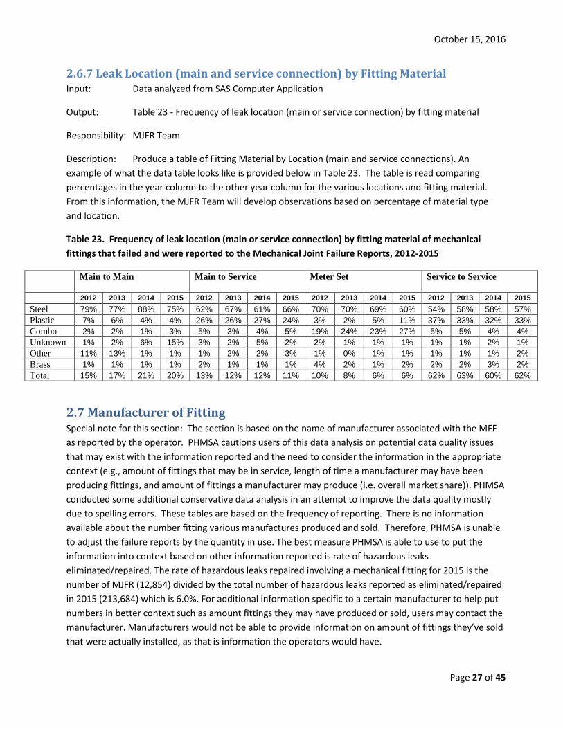
2.6.7 Leak Location (main and service connection) by Fitting Material .................................................... 27
2.7 Manufacturer of Fitting ............................................................................................................................ 27
2.7.1 Manufacturer of Fitting by Year Manufactured................................................................................ 28
2.7.2 Manufacturer by Years in Service ..................................................................................................... 29
2.7.3 Frequency of Manufacturers of Fittings ........................................................................................... 29
2.7.4 Manufacturer by Year of Failure ....................................................................................................... 30
2.7.5 Manufacturer by Leak Causes ........................................................................................................... 31
2.7.6 Manufacturer by Mechanical Fitting Involved .................................................................................. 33
2.8 Operators submitting MJFR ..................................................................................................................... 34
2.8.1 Frequency of Operator by Year of Failure ........................................................................................ 34
3.0 Future Analysis Ideas and Concepts ........................................................................................................ 42
3.1 Limitations ............................................................................................................................................ 42
3.2 Updates ................................................................................................................................................ 42
4.0 Technical Review and Analysis ................................................................................................................. 43
4.1 Overview of Analysis ............................................................................................................................ 43

October 15, 2016
Page 3 of 45
Mechanical Joint Failure Reporting Requirements
Mechanical Joint Failure Reports (MJFR) for the previous calendar year are required to be submitted to PHMSA by March 15th of the next year. Operators are required to submit their reports electronically through the PHMSA Pipeline Data Mart (PDM) system. This data is then available to PHMSA personnel in the PDM, and the data can be downloaded and analyzed. This procedure describes how PHMSA will process and analyze data from operators of gas distribution pipelines for mechanical fitting failures that resulted in a hazardous leak as required in §192.1009. The reporting requirements of §192.1009 are:
§192.1009 What must an operator report when compression couplings fail? (a) Except as provided in paragraph (b) of this section, each operator of a distribution pipeline system must submit a report on each mechanical fitting failure, excluding any failure that results only in a nonhazardous leak, on a Department of Transportation Form PHMSA F-7100.1-2. The report(s) must be submitted in accordance with § 191.12. (b) The mechanical fitting failure reporting requirements in paragraph (a) of this section do not apply to the following:
(1) Master meter operators; (2) Small LPG operator as defined in § 192.1001; or (3) LNG facilities.
The MJFR Form collects information on the particulars of hazardous leaks involving mechanical fittings so that any identified safety concerns can be addressed appropriately. Information collected includes the type of mechanical fitting involved, fitting material, manufacturer, year manufactured, year installed, the two materials being joined, leak location, and apparent cause of leak.
Overview
The PHMSA process for analyzing MJFR data is described in the following flowcharts and process descriptions along with expected outputs. The intent of the analysis to identify trends, and to that purpose, the following outputs are expected to be produced. These outputs are discussed in greater detail in this document.
• General information from MJFR reports (e.g., number of reports, number of operators, etc.) • Information pertaining to Material Type of the Fittings • Information pertaining to Leak Cause • Information pertaining to Type of Fitting Involved • Information pertaining to Leak Location • Information pertaining to Manufacturer of the Fitting • Operator Reporting • Future Analysis Ideas and Concepts • Technical Review and Analysis
The outputs will be analyzed and observations from the team’s perspective will be documented by the MJFR Team in an electronic format suitable for transmission and filling. The format may include more informal dissemination of information through the DIMP website or presentations and discussion with stakeholders, or if more formal action is needed, a Memorandum, Technical Report, Advisory Bulletin, or email transmission to PHMSA Associate Administrator. The MJFR team is comprised of PHMSA engineers, data analysts and other staff. Raw data and analysis on MJFR is available to the public at http://primis.phmsa.dot.gov/dimp/perfmeasures.htm .

October 15, 2016
Page 4 of 45
1.0 Receipt of Data and Initial Processing The MJFR Team will obtain the previous calendar year’s data from the PDM approximately one month following the deadline to allow for quality checks to be performed on the data by PHMSA IT personnel. The MJFR Team will scan the incoming data to ensure it meets their needs and note any issues to PHMSA IT personnel. Following the acceptance of the data for analysis purposes, the MJFR Team will begin analysis.
To better unitize the data submitted in the process, the MJFR Team categorizes the various spellings of manufactures uploaded into the data. The MJFR Team keeps the original submitted manufacturer name and the categorized name. The analysis is performed strictly on the categorized names.
2.0 Data Triaging and Analyses The MJFR Team members will analyze the MJFR data and generate the tables and charts outlined in this procedure. Typically the data from PDM is moved into a computer application called “SAS” in which the data is manipulated for analysis. The output from SAS is moved into PowerPoint for presentation and discussion purposes. Other evaluations and analyses may be performed depending upon the analysis.
2.1 Gather Information to Support Analysis and Review of Data Input: Excel Spreadsheet from PDM based on data received as of March 31, 2016
Output: Various tables and charts
Responsibility: MJFR Team
Description: The MJFR Team will use the following spreadsheets and tables to gather data in appropriate formats to support the analysis and review:
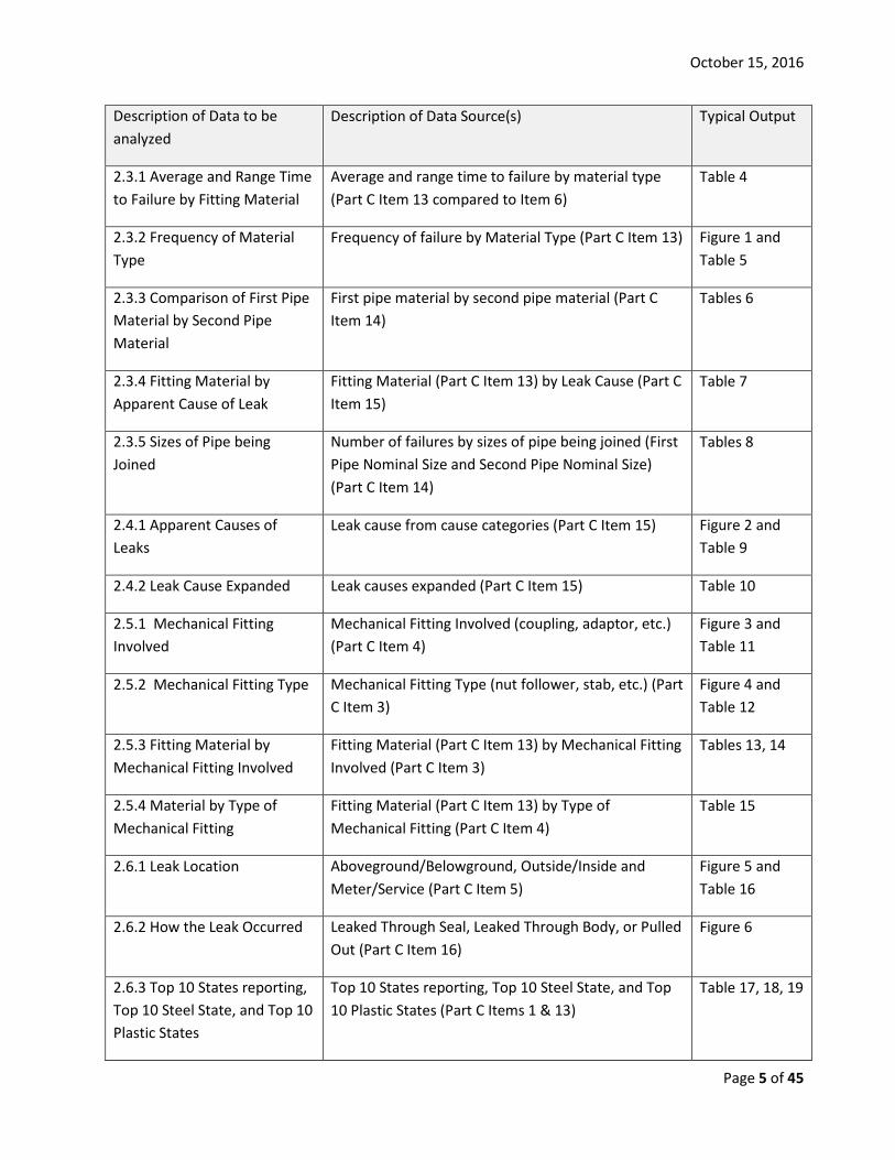
Table 1 – Spreadsheets and associated Tables required to perform analysis and expected Outputs
Description of Data to be analyzed
Description of Data Source(s) Typical Output
2.2.1 General Overview of the MJFR Information
Total number of reports, operators, manufacturers and the amounts of missing information for a given year
Table 1
2.2.2 General information on the Age of the Mechanical Fittings that Failed
Year of manufactured/installed, amounts of missing information, and average time to failure and range (Part C Items 6 & 7)
Table 2
2.2.3 Decade of Installation of Mechanical Fitting that Failed
Decade of installation of the mechanical fittings that failed (Part C Items 6 or 8)
Table 3
October 15, 2016
Page 5 of 45
Description of Data to be analyzed
Description of Data Source(s) Typical Output
2.3.1 Average and Range Time to Failure by Fitting Material
Average and range time to failure by material type (Part C Item 13 compared to Item 6)
Table 4
2.3.2 Frequency of Material Type
Frequency of failure by Material Type (Part C Item 13) Figure 1 and Table 5
2.3.3 Comparison of First Pipe Material by Second Pipe Material
First pipe material by second pipe material (Part C Item 14)
Tables 6
2.3.4 Fitting Material by Apparent Cause of Leak
Fitting Material (Part C Item 13) by Leak Cause (Part C Item 15)
Table 7
2.3.5 Sizes of Pipe being Joined
Number of failures by sizes of pipe being joined (First Pipe Nominal Size and Second Pipe Nominal Size) (Part C Item 14)
Tables 8
2.4.1 Apparent Causes of Leaks
Leak cause from cause categories (Part C Item 15) Figure 2 and Table 9
2.4.2 Leak Cause Expanded Leak causes expanded (Part C Item 15) Table 10
2.5.1 Mechanical Fitting Involved
Mechanical Fitting Involved (coupling, adaptor, etc.) (Part C Item 4)
Figure 3 and Table 11
2.5.2 Mechanical Fitting Type Mechanical Fitting Type (nut follower, stab, etc.) (Part C Item 3)
Figure 4 and Table 12
2.5.3 Fitting Material by Mechanical Fitting Involved
Fitting Material (Part C Item 13) by Mechanical Fitting Involved (Part C Item 3)
Tables 13, 14
2.5.4 Material by Type of Mechanical Fitting
Fitting Material (Part C Item 13) by Type of Mechanical Fitting (Part C Item 4)
Table 15
2.6.1 Leak Location Aboveground/Belowground, Outside/Inside and Meter/Service (Part C Item 5)
Figure 5 and Table 16
2.6.2 How the Leak Occurred Leaked Through Seal, Leaked Through Body, or Pulled Out (Part C Item 16)
Figure 6
2.6.3 Top 10 States reporting, Top 10 Steel State, and Top 10 Plastic States
Top 10 States reporting, Top 10 Steel State, and Top 10 Plastic States (Part C Items 1 & 13)
Table 17, 18, 19
October 15, 2016
Page 6 of 45
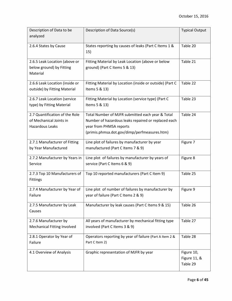
Description of Data to be analyzed
Description of Data Source(s) Typical Output
2.6.4 States by Cause States reporting by causes of leaks (Part C Items 1 & 15)
Table 20
2.6.5 Leak Location (above or below ground) by Fitting Material
Fitting Material by Leak Location (above or below ground) (Part C Items 5 & 13)
Table 21
2.6.6 Leak Location (inside or outside) by Fitting Material
Fitting Material by Location (inside or outside) (Part C Items 5 & 13)
Table 22
2.6.7 Leak Location (service type) by Fitting Material
Fitting Material by Location (service type) (Part C Items 5 & 13)
Table 23
2.7 Quantification of the Role of Mechanical Joints in Hazardous Leaks
Total Number of MJFR submitted each year & Total Number of hazardous leaks repaired or replaced each year from PHMSA reports (primis.phmsa.dot.gov/dimp/perfmeasures.htm)
Table 24
2.7.1 Manufacturer of Fitting by Year Manufactured
Line plot of failures by manufacturer by year manufactured (Part C Items 7 & 9)
Figure 7
2.7.2 Manufacturer by Years in Service
Line plot of failures by manufacturer by years of service (Part C Items 6 & 9)
Figure 8
2.7.3 Top 10 Manufacturers of Fittings
Top 10 reported manufacturers (Part C Item 9) Table 25
2.7.4 Manufacturer by Year of Failure
Line plot of number of failures by manufacturer by year of failure (Part C Items 2 & 9)
Figure 9
2.7.5 Manufacturer by Leak Causes
Manufacturer by leak causes (Part C Items 9 & 15) Table 26
2.7.6 Manufacturer by Mechanical Fitting Involved
All years of manufacturer by mechanical fitting type involved (Part C Items 3 & 9)
Table 27
2.8.1 Operator by Year of Failure
Operators reporting by year of failure (Part A Item 2 & Part C Item 2)
Table 28
4.1 Overview of Analysis Graphic representation of MJFR by year Figure 10, Figure 11, & Table 29
October 15, 2016
Page 7 of 45
2.2 General information from MJFR reports
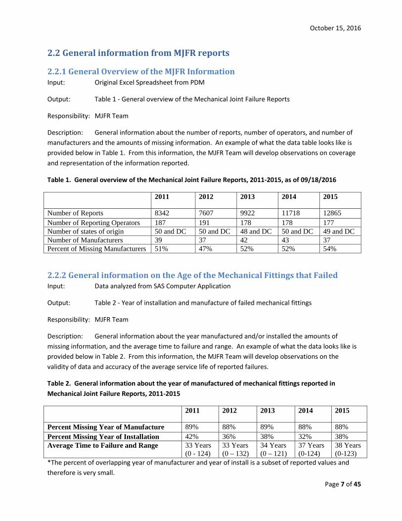
2.2.1 General Overview of the MJFR Information Input: Original Excel Spreadsheet from PDM
Output: Table 1 - General overview of the Mechanical Joint Failure Reports
Responsibility: MJFR Team
Description: General information about the number of reports, number of operators, and number of manufacturers and the amounts of missing information. An example of what the data table looks like is provided below in Table 1. From this information, the MJFR Team will develop observations on coverage and representation of the information reported.
Table 1. General overview of the Mechanical Joint Failure Reports, 2011-2015, as of 09/18/2016
2011 2012 2013 2014 2015
Number of Reports 8342 7607 9922 11718 12865 Number of Reporting Operators 187 191 178 178 177 Number of states of origin 50 and DC 50 and DC 48 and DC 50 and DC 49 and DC Number of Manufacturers 39 37 42 43 37 Percent of Missing Manufacturers 51% 47% 52% 52% 54%
2.2.2 General information on the Age of the Mechanical Fittings that Failed Input: Data analyzed from SAS Computer Application
Output: Table 2 - Year of installation and manufacture of failed mechanical fittings
Responsibility: MJFR Team
Description: General information about the year manufactured and/or installed the amounts of missing information, and the average time to failure and range. An example of what the data looks like is provided below in Table 2. From this information, the MJFR Team will develop observations on the validity of data and accuracy of the average service life of reported failures.
Table 2. General information about the year of manufactured of mechanical fittings reported in Mechanical Joint Failure Reports, 2011-2015
2011 2012 2013 2014 2015
Percent Missing Year of Manufacture 89% 88% 89% 88% 88% Percent Missing Year of Installation 42% 36% 38% 32% 38% Average Time to Failure and Range 33 Years
(0 - 124) 33 Years (0 – 132)
34 Years (0 – 121)
37 Years (0-124)
38 Years (0-123)
*The percent of overlapping year of manufacturer and year of install is a subset of reported values and therefore is very small.

October 15, 2016
Page 8 of 45
2.2.3 Decade of Installation of Mechanical Fitting that Failed Input: Data analyzed from SAS Computer Application
Output: Table 3 – Decade of installation of failed mechanical fittings
Responsibility: MJFR Team
Description: Produce a table of decade of installation of the mechanical fittings that failed. Compare percentage of this table to percentages from the annual reports about mileage installed in given decades. An example of what the data table looks like is provided below in Table 3. From this information, the MJFR Team will develop observations on the validity of the data because the distribution across the decades should be similar to the distribution of pipe across the decades from the annual reports.
Table 3. Decade of installation of mechanical fittings that failed and were reported to the Mechanical Joint Failure Reports, 2011-2015
2011 Count (%)
2012 Count (%)
2013 Count (%)
2014 Count (%)
2015 Count (%)
Pre 1940s 41 (2%) 22 (3%) 15 (3%) 14 (4%) 88 (18%) 1940s 23 (1%) 6 (1%) 25 (5%) 13 (4%) 27 (6%) 1950s 191 (11%) 70 (9%) 59 (13%) 31(8%) 56 (12%) 1960s 337 (19%) 168 (21%) 91 (19%) 53(14%) 60(13%) 1970s 483 (27%) 232 (29%) 122 (25%) 81 (22%) 98 (21%) 1980s 379 (21%) 185 (24%) 82 (17%) 101 (27%) 95 (20%) 1990s 155 (9%) 60 (8%) 51 (11%) 59 (15%) 37 (7%) 2000s 164 (9%) 33 (4%) 27 (6%) 15 (4%) 10 (2%) 2010s 5 (1%) 6 (1%) 3 (1%) 6 (2%) 1 (1%)
2.3 Fitting Material and Pipe Type
2.3.1 Average and Range Time to Failure by Fitting Material Input: Data analyzed from SAS Computer Application
Output: Table 4 - Average time to failure by fitting material type
Responsibility: MJFR Team
Description: Produce a table of average and range time to failure by fitting material (Part C Item 13 of the form). An example of what the data table looks like is provided below in Table 4. Based on all data and other information, when the year of manufactured and the year of install are both reported, the majority of the dates are within a year of each other. Since, the dates are similar and there year of install is reported more, table 4 will use year of install. From this information, the MJFR Team will develop observations on time to failure on various fitting material types.
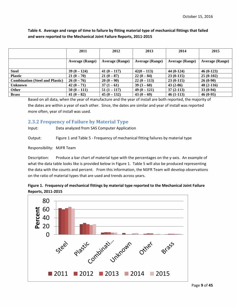
October 15, 2016
Page 9 of 45
Table 4. Average and range of time to failure by fitting material type of mechanical fittings that failed and were reported to the Mechanical Joint Failure Reports, 2011-2015
Based on all data, when the year of manufacture and the year of install are both reported, the majority of the dates are within a year of each other. Since, the dates are similar and year of install was reported more often, year of install was used.
2.3.2 Frequency of Failure by Material Type Input: Data analyzed from SAS Computer Application
Output: Figure 1 and Table 5 - Frequency of mechanical fitting failures by material type
Responsibility: MJFR Team
Description: Produce a bar chart of material type with the percentages on the y-axis. An example of what the data table looks like is provided below in Figure 1. Table 5 will also be produced representing the data with the counts and percent. From this information, the MJFR Team will develop observations on the ratio of material types that are used and trends across years.
Figure 1. Frequency of mechanical fittings by material type reported to the Mechanical Joint Failure Reports, 2011-2015
020406080
Perc
ent
2011 2012 2013 2014 2015
2011 2012 2013 2014 2015
Average (Range) Average (Range) Average (Range) Average (Range) Average (Range)
Steel 39 (0 – 124) 41 (0 – 117) 42(0 – 113) 44 (0-124) 46 (0-123) Plastic 21 (0 – 70) 21 (0 – 87) 22 (0 – 84) 23 (0-115) 25 (0-102) Combination (Steel and Plastic) 26 (0 – 76) 20 (0 – 90) 22 (0 – 113) 23 (0-115) 26 (0-90) Unknown 42 (0 – 71) 37 (1 – 61) 39 (3 – 60) 43 (2-86) 48 (2-116) Other 50 (0 – 111) 51 (1 – 117) 49 (0 – 121) 37 (2-113) 33 (0-94) Brass 41 (0 – 82) 45 (0 – 132) 43 (0 – 69) 46 (1-113) 46 (0-95)
October 15, 2016
Page 10 of 45
Table 5. Frequency of mechanical fittings by material type reported to the Mechanical Joint Failure Reports, 2011-2015
2011 Count (%)
2012 Count (%)
2013 Count (%)
2014 Count (%)
2015 Count (%)
Steel 5239 (63%)
4610 (60%)
6260 (63%)
7670 (66%)
7957 (62%)
Plastic 2071 (25%)
2097 (28%)
2498 (25%)
2735 (23%)
3161 (25%)
Combination (Steel and Plastic)
455 (5%)
450 (6%)
555 (6%)
567 (6%)
698 (5%)
Unknown 344 (4%)
94 (1%)
127 (1%)
364 (3%)
518 (4%)
Other 165 (2%)
192 (3%)
297 (3%)
127 (1%)
263 (2%)
Brass 82 (1%)
171 (2%)
93 (2%)
93 (2%)
257 (2%)
2.3.3 Comparison of First Pipe Material by Second Pipe Material Type Input: Data analyzed from SAS Computer Application
Output: Table 6 – Comparisons of first pipe and second pipe materials being joined where mechanical fitting failure occurred
Responsibility: MJFR Team
Description: Produce a table comparing first pipe material and second pipe material (Part C Item 14). The highest numbers and percentages should be in the diagonal. Along with the table list the percentage of pipe material that had some plastic and the percentage of pipe material that had some steel. An example of what the data table looks like is provided below: Table 6 provides a summary of all the data submitted. From this information, the MJFR Team will develop observations on how the various material types are combined. The various tables will also help identify any outliers.
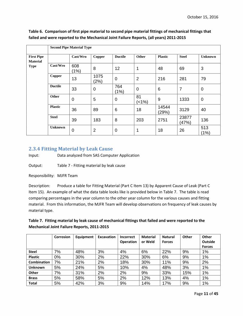
October 15, 2016
Page 11 of 45
Table 6. Comparison of first pipe material to second pipe material fittings of mechanical fittings that failed and were reported to the Mechanical Joint Failure Reports, (all years) 2011-2015
Second Pipe Material Type
First Pipe Material Type
Cast/Wro Copper Ductile Other Plastic Steel Unknown
Cast/Wro 608 (1%) 8 12 1 48 69 3
Copper 13 1075
(2%) 0 2 216 281 79 Ductile
33 0 764 (1%) 0 6 7 0
Other 0 5 0 81
(<1%) 9 1333 0 Plastic
36 89 6 18 14544 (29%) 3129 40
Steel 39 183 8 203 2751 23877
(47%) 136 Unknown
0 2 0 1 18 26 513 (1%)
2.3.4 Fitting Material by Leak Cause Input: Data analyzed from SAS Computer Application
Output: Table 7 - Fitting material by leak cause
Responsibility: MJFR Team
Description: Produce a table for Fitting Material (Part C Item 13) by Apparent Cause of Leak (Part C Item 15). An example of what the data table looks like is provided below in Table 7. The table is read comparing percentages in the year column to the other year column for the various causes and fitting material. From this information, the MJFR Team will develop observations on frequency of leak causes by material type.
Table 7. Fitting material by leak cause of mechanical fittings that failed and were reported to the Mechanical Joint Failure Reports, 2011-2015
Corrosion Equipment Excavation Incorrect Operation
Material or Weld
Natural Forces
Other Other Outside Forces
Steel 7% 48% 3% 4% 6% 22% 9% 1% Plastic 0% 30% 2% 22% 30% 6% 9% 1% Combination 7% 21% 2% 18% 30% 11% 9% 2% Unknown 5% 24% 5% 10% 4% 48% 3% 1% Other 7% 31% 2% 2% 9% 33% 15% 1% Brass 5% 58% 5% 2% 12% 13% 4% 1% Total 5% 42% 3% 9% 14% 17% 9% 1%

October 15, 2016
Page 12 of 45
2.3.5 Sizes of Pipe being Joined Input: Data analyzed from SAS Computer Application
Output: Table 8 - Comparisons of first pipe and second pipe sizes being joined where mechanical fitting failure occurred
Responsibility: MJFR Team
Description: Produce a plot of the number of failures by pipe sizes being joined (Part C Item 14, First Pipe Nominal Size and Second Pipe Nominal Size). An example of what the data table looks like is provided below in Table 8. First pipe size is reflected in the rows and Second pipe size is reflected in the columns. From this information, the MJFR Team will develop observations on the number of reported failures from joining various pipe sizes with mechanical fittings.
Table 8. Sizes of pipe being joined by mechanical fittings that failed and were reported to the Mechanical Joint Failure Reports, (all years) 2011-2015
¼ inch
½ inch
¾ inch 1 inch 1 ¼
inch 1 ½ inch
1 ¾ inch 2 inch 3
inch 4
inch 6
inch
8 inch or
larger ¼ inch
97 (<1%)
48 26 7 3 3 0 2 0 0 0 0 ½ inch 46
7304
(15%) 2305 620 26 22 0 157 5 17 5 2
¾ inch 18 1182
8646 (17%)
286 43 37 0 226 9 25 6 4 1 inch 8 424 346
11447 (24%)
105 62 2 77 9 23 8 3 1 ¼ inch 4 95 107 211
2001 (5%)
537 1 59 11 13 4 2 1 ½ inch 0 5 6 24 20
253 (1%)
0 1 0 1 0 1 1 ¾ inch 0 1 3 1 2 1
3 (0%)
0 0 0 0 0 2 inch 2 435 378 260 53 67 5
6695 (14%)
25 12 8 4 3 inch 0 19 29 33 7 13 0 31
243 (1%)
5 1 0 4 inch 0 46 36 70 17 16 0 39 7
825 (2%)
11 1 6 inch 0 13 9 21 4 9 0 17 8 6
780 (2%)
1 8 inch or larger
1 40 42 64 3 868 0 21 7 3 14 692 (1%)
Percentages are rounded based on total number
October 15, 2016
Page 13 of 45
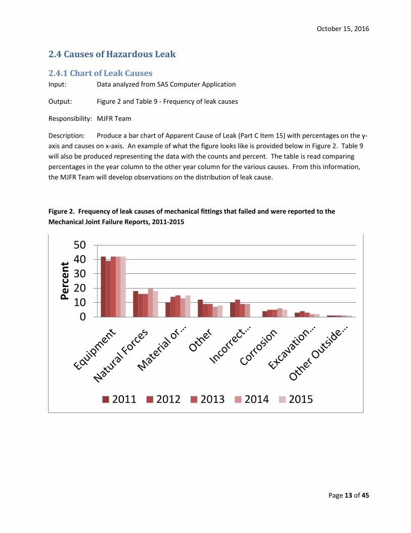
2.4 Causes of Hazardous Leak
2.4.1 Chart of Leak Causes Input: Data analyzed from SAS Computer Application
Output: Figure 2 and Table 9 - Frequency of leak causes
Responsibility: MJFR Team
Description: Produce a bar chart of Apparent Cause of Leak (Part C Item 15) with percentages on the y-axis and causes on x-axis. An example of what the figure looks like is provided below in Figure 2. Table 9 will also be produced representing the data with the counts and percent. The table is read comparing percentages in the year column to the other year column for the various causes. From this information, the MJFR Team will develop observations on the distribution of leak cause.
Figure 2. Frequency of leak causes of mechanical fittings that failed and were reported to the Mechanical Joint Failure Reports, 2011-2015
01020304050
Perc
ent
2011 2012 2013 2014 2015

October 15, 2016
Page 14 of 45
Table 9. Frequency of leak causes of mechanical fittings that failed and were reported to the Mechanical Joint Failure Reports, 2011-2015
2011 Count (%)
2012 Count (%)
2013 Count (%)
2014 Count (%)
2015 Count (%)
Equipment 3506 (42%)
2985 (39%)
4214 (42%)
4898 (42%)
5445 (42%)
Natural Forces 1558 (18%)
1201 (16%)
1614 (16%)
2336 (20%)
2318 (18%)
Material or Weld 802 (10%)
1093 (14%)
1483 (15%)
1571 (13%)
1994 (15%)
Other 1003 (12%)
718 (9%)
880 (9%)
852 (7%)
970 (8%)
Incorrect Operation 807 (10%)
876 (12%)
910 (9%)
1067 (9%)
1097 (9%)
Corrosion 332 (4%)
389 (5%)
534 (5%)
692 (6%)
654 (5%)
Excavation 229 (3%)
266 (4%)
223 (3%)
255 (2%)
294 (2%)
Other Outside Force Damage
105 (1%)
79 (1%)
62 (1%)
47 (1%)
82 (1%)
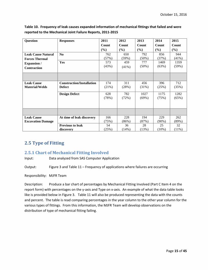
2.4.2 Leak Causes Expanded Input: Data analyzed from SAS Computer Application
Output: Table 10 - Frequency of leak causes (expanded)
Responsibility: MJFR Team
Description: Produce a table with leak causes expanded as the title and Leak Cause Natural Forces Thermal Expansion/Contraction, Leak Cause Material/Welds and Leak Cause Excavation Damage Occurred presenting both the count and percent by report year. An example of what the data table looks like is provided below in Table 10. The table is read comparing percentages in the year column to the other year column for the various questions. From this information, the MJFR Team will develop observations on any issues identified in specific leak causes.
October 15, 2016
Page 15 of 45
Table 10. Frequency of leak causes expanded information of mechanical fittings that failed and were reported to the Mechanical Joint Failure Reports, 2011-2015
Question Responses 2011 Count (%)
2012 Count (%)
2013 Count (%)
2014 Count (%)
2015 Count (%)
Leak Cause Natural Forces Thermal Expansion / Contraction
No 762 (57%)
650 (59%)
792 (50%)
856 (37%)
944 (41%)
Yes 573 (43%)
459 (41%)
777 (50%)
1469 (63%)
1359 (59%)
Leak Cause Material/Welds
Construction/Installation Defect
174 (21%)
311 (28%)
456 (31%)
396 (25%)
712 (35%)
Design Defect 628 (78%)
782 (72%)
1027 (69%)
1175 (75%)
1282 (65%)
Leak Cause Excavation Damage
At time of leak discovery 166 (75%)
228 (86%)
194 (87%)
229 (90%)
262 (89%)
Previous to leak discovery
54 (25%)
36 (14%)
28 (13%)
25 (10%)
32 (11%)
2.5 Type of Fitting
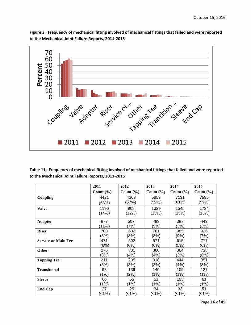
2.5.1 Chart of Mechanical Fitting Involved Input: Data analyzed from SAS Computer Application
Output: Figure 3 and Table 11 – Frequency of applications where failures are occurring
Responsibility: MJFR Team
Description: Produce a bar chart of percentages by Mechanical Fitting Involved (Part C Item 4 on the report form) with percentages on the y-axis and Type on x-axis. An example of what the data table looks like is provided below in Figure 3. Table 11 will also be produced representing the data with the counts and percent. The table is read comparing percentages in the year column to the other year column for the various types of fittings. From this information, the MJFR Team will develop observations on the distribution of type of mechanical fitting failing.
October 15, 2016
Page 16 of 45
Figure 3. Frequency of mechanical fitting involved of mechanical fittings that failed and were reported to the Mechanical Joint Failure Reports, 2011-2015
Table 11. Frequency of mechanical fitting involved of mechanical fittings that failed and were reported to the Mechanical Joint Failure Reports, 2011-2015
2011 Count (%)
2012 Count (%)
2013 Count (%)
2014 Count (%)
2015 Count (%)
Coupling 4421 (53%)
4363 (57%)
5853 (59%)
7131 (61%)
7595 (59%)
Valve 1196 (14%)
908 (12%)
1339 (13%)
1545 (13%)
1734 (13%)
Adapter 877 (11%)
507 (7%)
493 (5%)
387 (3%)
442 (3%)
Riser 700 (8%)
602 (8%)
761 (8%)
985 (9%)
926 (7%)
Service or Main Tee 471 (6%)
502 (6%)
571 (6%)
615 (5%)
777 (6%)
Other 275 (3%)
301 (4%)
360 (4%)
364 (3%)
738 (6%)
Tapping Tee 211 (3%)
205 (3%)
318 (3%)
444 (4%)
351 (3%)
Transitional 98 (1%)
139 (2%)
140 (1%)
109 (1%)
127 (1%)
Sleeve 66 (1%)
55 (1%)
51 (1%)
103 (1%)
61 (1%)
End Cap 27 (<1%)
25 (<1%)
34 (<1%)
33 (<1%)
51 (<1%)
010203040506070
Perc
ent
2011 2012 2013 2014 2015
October 15, 2016
Page 17 of 45
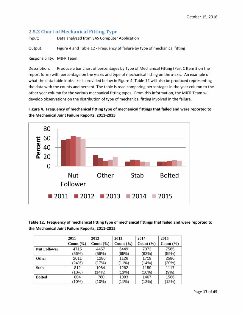
2.5.2 Chart of Mechanical Fitting Type Input: Data analyzed from SAS Computer Application
Output: Figure 4 and Table 12 - Frequency of failure by type of mechanical fitting
Responsibility: MJFR Team
Description: Produce a bar chart of percentages by Type of Mechanical Fitting (Part C Item 3 on the report form) with percentage on the y-axis and type of mechanical fitting on the x-axis. An example of what the data table looks like is provided below in Figure 4. Table 12 will also be produced representing the data with the counts and percent. The table is read comparing percentages in the year column to the other year column for the various mechanical fitting types. From this information, the MJFR Team will develop observations on the distribution of type of mechanical fitting involved in the failure.
Figure 4. Frequency of mechanical fitting type of mechanical fittings that failed and were reported to the Mechanical Joint Failure Reports, 2011-2015
Table 12. Frequency of mechanical fitting type of mechanical fittings that failed and were reported to the Mechanical Joint Failure Reports, 2011-2015
2011 Count (%)
2012 Count (%)
2013 Count (%)
2014 Count (%)
2015 Count (%)
Nut Follower 4715 (56%)
4457 (59%)
6449 (65%)
7373 (63%)
7585 (59%)
Other 2011 (24%)
1286 (17%)
1126 (11%)
1719 (14%)
2586 (20%)
Stab 812 (10%)
1084 (14%)
1262 (13%)
1159 (10%)
1117 (9%)
Bolted 804 (10%)
780 (10%)
1083 (11%)
1467 (13%)
1566 (12%)
020406080
NutFollower
Other Stab Bolted
Perc
ent
2011 2012 2013 2014 2015
October 15, 2016
Page 18 of 45
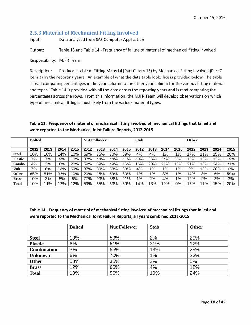
2.5.3 Material of Mechanical Fitting Involved Input: Data analyzed from SAS Computer Application
Output: Table 13 and Table 14 - Frequency of failure of material of mechanical fitting involved
Responsibility: MJFR Team
Description: Produce a table of Fitting Material (Part C Item 13) by Mechanical Fitting Involved (Part C Item 3) by the reporting years. An example of what the data table looks like is provided below. The table is read comparing percentages in the year column to the other year column for the various fitting material and types. Table 14 is provided with all the data across the reporting years and is read comparing the percentages across the rows. From this information, the MJFR Team will develop observations on which type of mechanical fitting is most likely from the various material types.
Table 13. Frequency of material of mechanical fitting involved of mechanical fittings that failed and were reported to the Mechanical Joint Failure Reports, 2012-2015
Bolted Nut Follower Stab Other
2012 2013 2014 2015 2012 2013 2014 2015 2012 2013 2014 2015 2012 2013 2014 2015 Steel 10% 10% 14% 10% 69% 75% 70% 69% 4% 4% 1% 1% 17% 11% 15% 20% Plastic 7% 7% 9% 10% 37% 44% 44% 41% 40% 36% 34% 30% 16% 13% 13% 19% Combo 4% 3% 6% 20% 59% 59% 49% 46% 16% 20% 21% 13% 21% 18% 24% 21% Unk 7% 6% 13% 60% 87% 80% 58% 33% 4% 1% 1% 1% 2% 13% 28% 6% Other 65% 81% 32% 10% 20% 15% 59% 30% 1% 1% 3% 1% 14% 3% 6% 59% Brass 10% 3% 5% 5% 77% 93% 88% 91% 1% 2% 4% 1% 12% 2% 3% 3% Total 10% 11% 12% 12% 59% 65% 63% 59% 14% 13% 10% 9% 17% 11% 15% 20%
Table 14. Frequency of material of mechanical fitting involved of mechanical fittings that failed and were reported to the Mechanical Joint Failure Reports, all years combined 2011-2015
Bolted Nut Follower Stab Other
Steel 10% 59% 2% 29% Plastic 6% 51% 31% 12% Combination 3% 55% 13% 29% Unknown 6% 70% 1% 23% Other 58% 35% 2% 5% Brass 12% 66% 4% 18% Total 10% 56% 10% 24%
October 15, 2016
Page 19 of 45
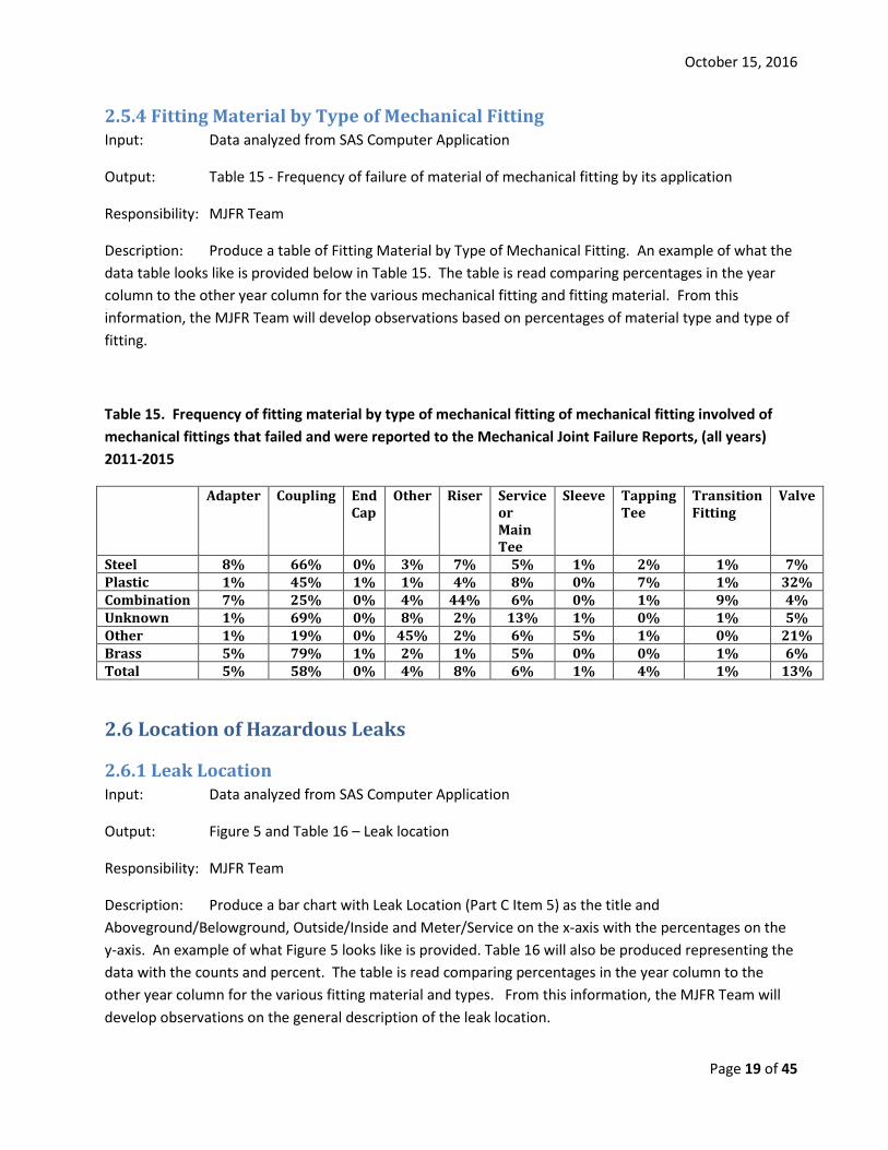
2.5.4 Fitting Material by Type of Mechanical Fitting Input: Data analyzed from SAS Computer Application
Output: Table 15 - Frequency of failure of material of mechanical fitting by its application
Responsibility: MJFR Team
Description: Produce a table of Fitting Material by Type of Mechanical Fitting. An example of what the data table looks like is provided below in Table 15. The table is read comparing percentages in the year column to the other year column for the various mechanical fitting and fitting material. From this information, the MJFR Team will develop observations based on percentages of material type and type of fitting.
Table 15. Frequency of fitting material by type of mechanical fitting of mechanical fitting involved of mechanical fittings that failed and were reported to the Mechanical Joint Failure Reports, (all years) 2011-2015
Adapter Coupling End Cap
Other Riser Service or Main Tee
Sleeve Tapping Tee
Transition Fitting
Valve
Steel 8% 66% 0% 3% 7% 5% 1% 2% 1% 7% Plastic 1% 45% 1% 1% 4% 8% 0% 7% 1% 32% Combination 7% 25% 0% 4% 44% 6% 0% 1% 9% 4% Unknown 1% 69% 0% 8% 2% 13% 1% 0% 1% 5% Other 1% 19% 0% 45% 2% 6% 5% 1% 0% 21% Brass 5% 79% 1% 2% 1% 5% 0% 0% 1% 6% Total 5% 58% 0% 4% 8% 6% 1% 4% 1% 13%
2.6 Location of Hazardous Leaks
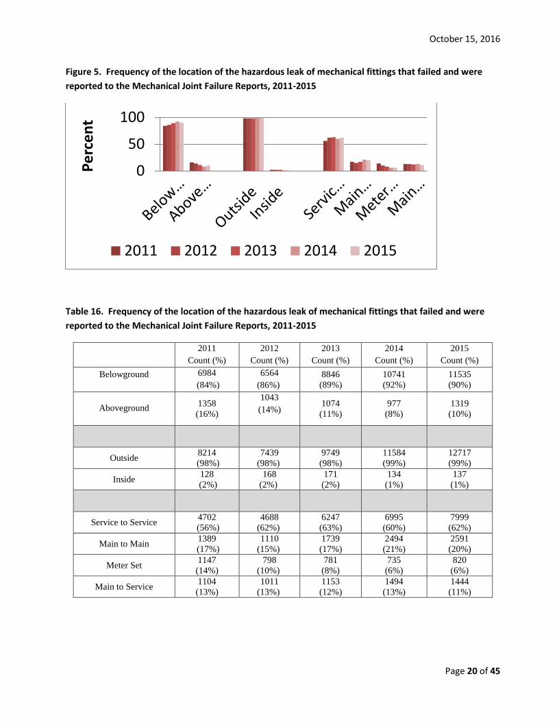
2.6.1 Leak Location Input: Data analyzed from SAS Computer Application
Output: Figure 5 and Table 16 – Leak location
Responsibility: MJFR Team
Description: Produce a bar chart with Leak Location (Part C Item 5) as the title and Aboveground/Belowground, Outside/Inside and Meter/Service on the x-axis with the percentages on the y-axis. An example of what Figure 5 looks like is provided. Table 16 will also be produced representing the data with the counts and percent. The table is read comparing percentages in the year column to the other year column for the various fitting material and types. From this information, the MJFR Team will develop observations on the general description of the leak location.
October 15, 2016
Page 20 of 45
Figure 5. Frequency of the location of the hazardous leak of mechanical fittings that failed and were reported to the Mechanical Joint Failure Reports, 2011-2015
Table 16. Frequency of the location of the hazardous leak of mechanical fittings that failed and were reported to the Mechanical Joint Failure Reports, 2011-2015
2011 Count (%)
2012 Count (%)
2013 Count (%)
2014 Count (%)
2015 Count (%)
Belowground 6984 (84%)
6564 (86%)
8846 (89%)
10741 (92%)
11535 (90%)
Aboveground 1358 (16%)
1043 (14%)
1074 (11%)
977 (8%)
1319 (10%)
Outside 8214 (98%)
7439 (98%)
9749 (98%)
11584 (99%)
12717 (99%)
Inside 128 (2%)
168 (2%)
171 (2%)
134 (1%)
137 (1%)
Service to Service 4702 (56%)
4688 (62%)
6247 (63%)
6995 (60%)
7999 (62%)
Main to Main 1389 (17%)
1110 (15%)
1739 (17%)
2494 (21%)
2591 (20%)
Meter Set 1147 (14%)
798 (10%)
781 (8%)
735 (6%)
820 (6%)
Main to Service 1104 (13%)
1011 (13%)
1153 (12%)
1494 (13%)
1444 (11%)
0
50
100
Perc
ent
2011 2012 2013 2014 2015
October 15, 2016
Page 21 of 45
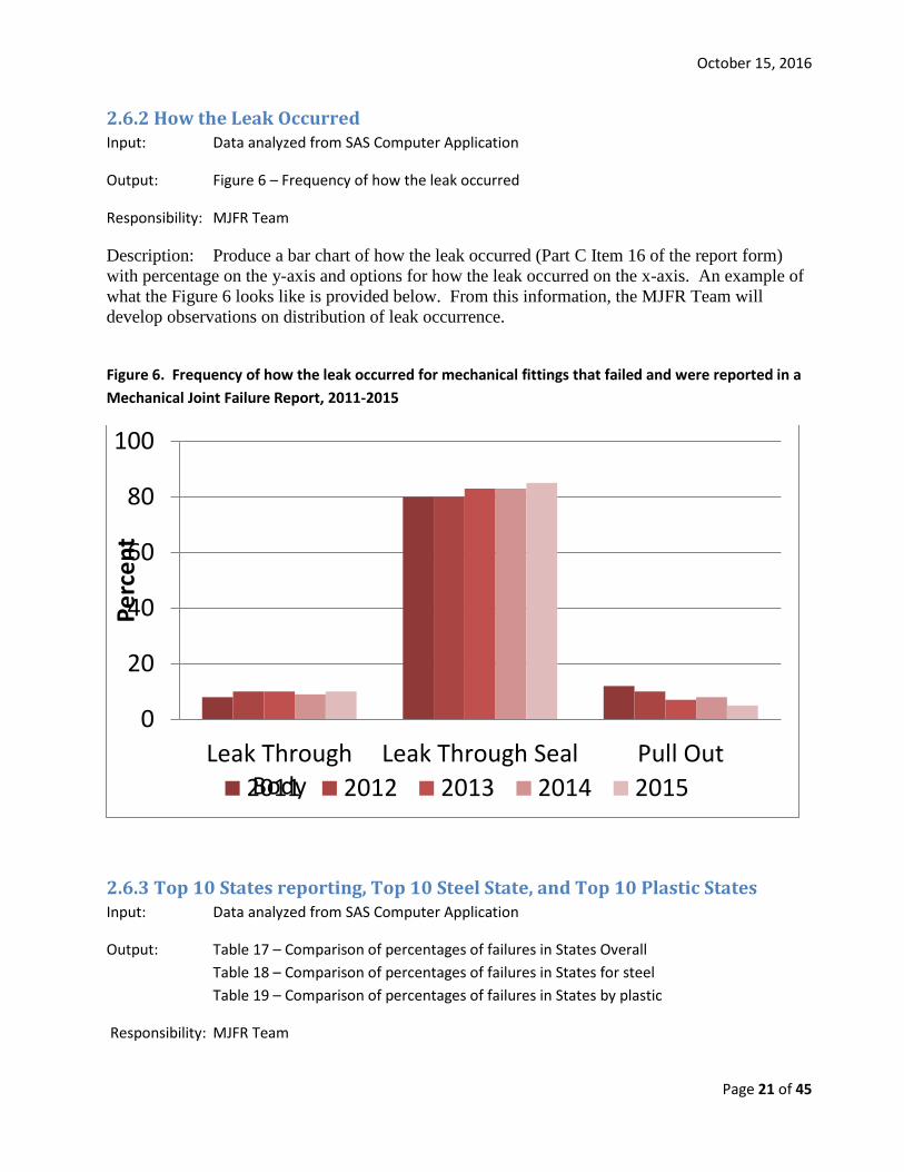
2.6.2 How the Leak Occurred Input: Data analyzed from SAS Computer Application
Output: Figure 6 – Frequency of how the leak occurred
Responsibility: MJFR Team
Description: Produce a bar chart of how the leak occurred (Part C Item 16 of the report form) with percentage on the y-axis and options for how the leak occurred on the x-axis. An example of what the Figure 6 looks like is provided below. From this information, the MJFR Team will develop observations on distribution of leak occurrence.
Figure 6. Frequency of how the leak occurred for mechanical fittings that failed and were reported in a Mechanical Joint Failure Report, 2011-2015
2.6.3 Top 10 States reporting, Top 10 Steel State, and Top 10 Plastic States Input: Data analyzed from SAS Computer Application
Output: Table 17 – Comparison of percentages of failures in States Overall Table 18 – Comparison of percentages of failures in States for steel Table 19 – Comparison of percentages of failures in States by plastic
Responsibility: MJFR Team
0
20
40
60
80
100
Leak ThroughBody
Leak Through Seal Pull Out
Perc
ent
2011 2012 2013 2014 2015
October 15, 2016
Page 22 of 45
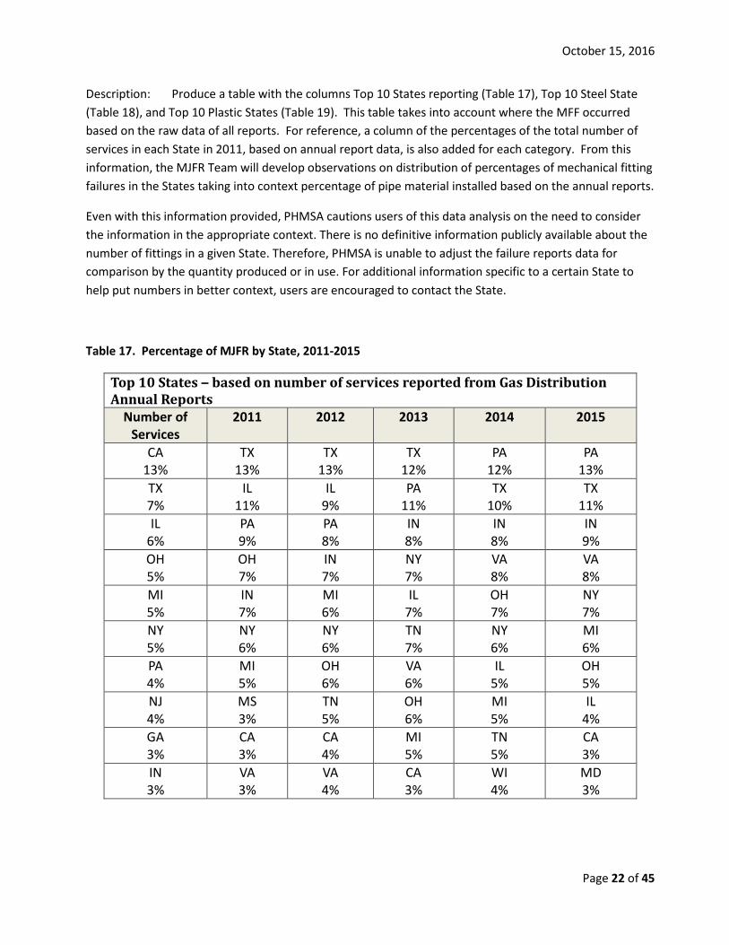
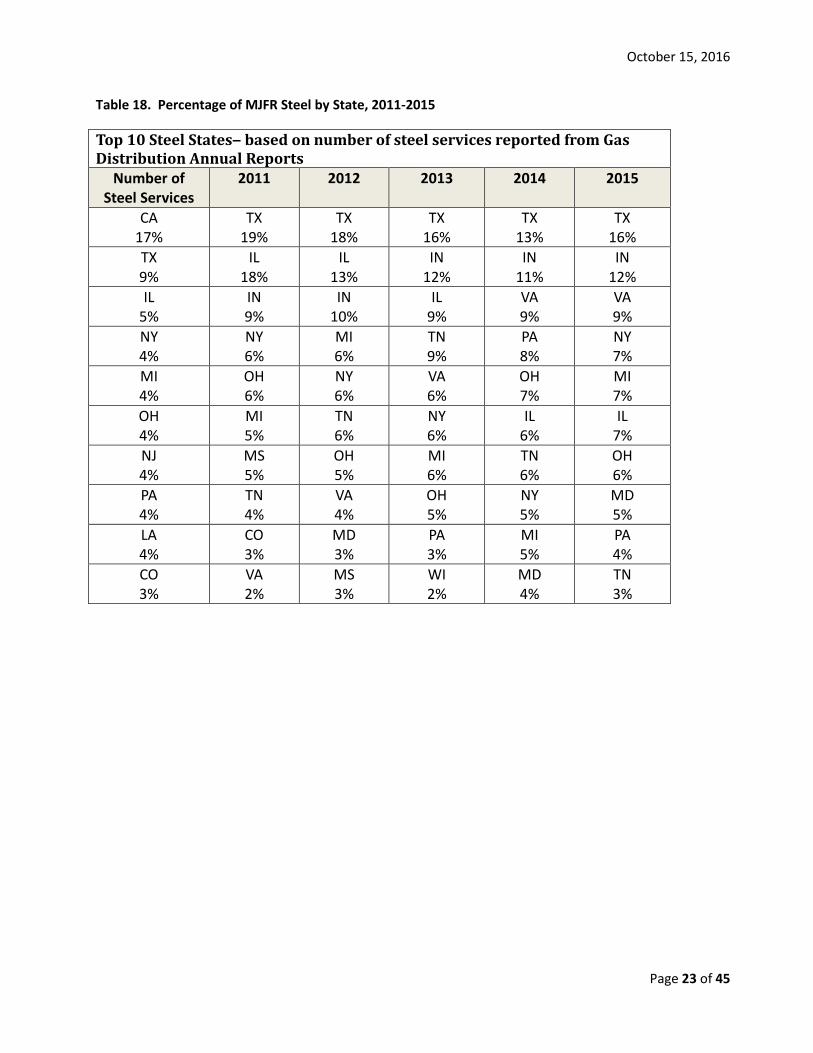
Description: Produce a table with the columns Top 10 States reporting (Table 17), Top 10 Steel State (Table 18), and Top 10 Plastic States (Table 19). This table takes into account where the MFF occurred based on the raw data of all reports. For reference, a column of the percentages of the total number of services in each State in 2011, based on annual report data, is also added for each category. From this information, the MJFR Team will develop observations on distribution of percentages of mechanical fitting failures in the States taking into context percentage of pipe material installed based on the annual reports.
Even with this information provided, PHMSA cautions users of this data analysis on the need to consider the information in the appropriate context. There is no definitive information publicly available about the number of fittings in a given State. Therefore, PHMSA is unable to adjust the failure reports data for comparison by the quantity produced or in use. For additional information specific to a certain State to help put numbers in better context, users are encouraged to contact the State.
Table 17. Percentage of MJFR by State, 2011-2015
Top 10 States – based on number of services reported from Gas Distribution Annual Reports
Number of Services
2011 2012 2013 2014 2015
CA 13%
TX 13%
TX 13%
TX 12%
PA 12%
PA 13%
TX 7%
IL 11%
IL 9%
PA 11%
TX 10%
TX 11%
IL 6%
PA 9%
PA 8%
IN 8%
IN 8%
IN 9%
OH 5%
OH 7%
IN 7%
NY 7%
VA 8%
VA 8%
MI 5%
IN 7%
MI 6%
IL 7%
OH 7%
NY 7%
NY 5%
NY 6%
NY 6%
TN 7%
NY 6%
MI 6%
PA 4%
MI 5%
OH 6%
VA 6%
IL 5%
OH 5%
NJ 4%
MS 3%
TN 5%
OH 6%
MI 5%
IL 4%
GA 3%
CA 3%
CA 4%
MI 5%
TN 5%
CA 3%
IN 3%
VA 3%
VA 4%
CA 3%
WI 4%
MD 3%
October 15, 2016
Page 23 of 45
Table 18. Percentage of MJFR Steel by State, 2011-2015
Top 10 Steel States– based on number of steel services reported from Gas Distribution Annual Reports
Number of Steel Services
2011 2012 2013 2014 2015
CA 17%
TX 19%
TX 18%
TX 16%
TX 13%
TX 16%
TX 9%
IL 18%
IL 13%
IN 12%
IN 11%
IN 12%
IL 5%
IN 9%
IN 10%
IL 9%
VA 9%
VA 9%
NY 4%
NY 6%
MI 6%
TN 9%
PA 8%
NY 7%
MI 4%
OH 6%
NY 6%
VA 6%
OH 7%
MI 7%
OH 4%
MI 5%
TN 6%
NY 6%
IL 6%
IL 7%
NJ 4%
MS 5%
OH 5%
MI 6%
TN 6%
OH 6%
PA 4%
TN 4%
VA 4%
OH 5%
NY 5%
MD 5%
LA 4%
CO 3%
MD 3%
PA 3%
MI 5%
PA 4%
CO 3%
VA 2%
MS 3%
WI 2%
MD 4%
TN 3%

October 15, 2016
Page 24 of 45
Table 19. Percentage of MJFR Plastic by State, 2011-2015
Top 10 Plastic States - – based on number of plastic services reported from Gas Distribution Annual Reports
Number of Plastic Services
2011 2012 2013 2014 2015
CA 12%
PA 26%
PA 20%
PA 22%
PA 23%
PA 26%
TX 7%
OH 11%
CA 14%
CA 12%
OH 9%
CA 13%
OH 5%
CA 10%
OH 7%
OH 8%
CA 8%
OH 7%
NY 5%
NY 5%
NY 6%
NY 8%
VA 7%
NY 5%
MI 5%
GA 4%
AZ 5%
VA 6%
NY 6%
VA 5%
PA 5%
CT 4%
NV 4%
NV 4%
WI 5%
NV 4%
IL 5%
MA 4%
VA 4%
AZ 3%
GA 3%
AZ 4%
NJ 3%
MO 3%
TN 3%
TN 3%
TN 3%
WI 3%
GA 3%
SC 3%
TX 3%
CT 3%
TX 3%
MA 3%
IN 3%
AZ 3%
CT 3%
MA 3%
CT 3%
TN 2%
2.6.4 States by Causes of Hazardous Leak Input: Data analyzed from SAS Computer Application
Output: Table 20 - Comparison of frequency of failures in States by cause
Responsibility: MJFR Team
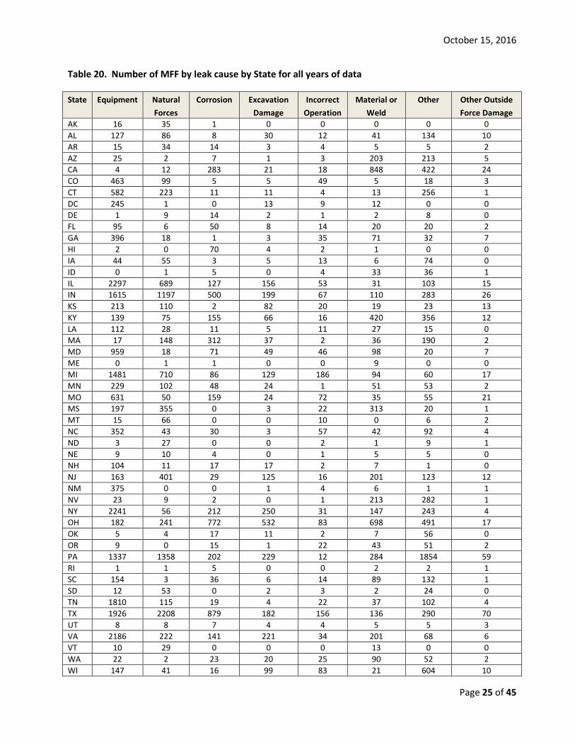
Description: Produce a table with the columns of states reporting and causes of leaks for all years of data. From this information, the MJFR Team will develop observations on distribution of which states the failures are occurring and the distribution of the causes in states.
October 15, 2016
Page 25 of 45
Table 20. Number of MFF by leak cause by State for all years of data
State Equipment Natural Forces
Corrosion Excavation Damage
Incorrect Operation
Material or Weld
Other Other Outside Force Damage
AK 16 35 1 0 0 0 0 0 AL 127 86 8 30 12 41 134 10 AR 15 34 14 3 4 5 5 2 AZ 25 2 7 1 3 203 213 5 CA 4 12 283 21 18 848 422 24 CO 463 99 5 5 49 5 18 3 CT 582 223 11 11 4 13 256 1 DC 245 1 0 13 9 12 0 0 DE 1 9 14 2 1 2 8 0 FL 95 6 50 8 14 20 20 2 GA 396 18 1 3 35 71 32 7 HI 2 0 70 4 2 1 0 0 IA 44 55 3 5 13 6 74 0 ID 0 1 5 0 4 33 36 1 IL 2297 689 127 156 53 31 103 15 IN 1615 1197 500 199 67 110 283 26 KS 213 110 2 82 20 19 23 13 KY 139 75 155 66 16 420 356 12 LA 112 28 11 5 11 27 15 0 MA 17 148 312 37 2 36 190 2 MD 959 18 71 49 46 98 20 7 ME 0 1 1 0 0 9 0 0 MI 1481 710 86 129 186 94 60 17 MN 229 102 48 24 1 51 53 2 MO 631 50 159 24 72 35 55 21 MS 197 355 0 3 22 313 20 1 MT 15 66 0 0 10 0 6 2 NC 352 43 30 3 57 42 92 4 ND 3 27 0 0 2 1 9 1 NE 9 10 4 0 1 5 5 0 NH 104 11 17 17 2 7 1 0 NJ 163 401 29 125 16 201 123 12 NM 375 0 0 1 4 6 1 1 NV 23 9 2 0 1 213 282 1 NY 2241 56 212 250 31 147 243 4 OH 182 241 772 532 83 698 491 17 OK 5 4 17 11 2 7 56 0 OR 9 0 15 1 22 43 51 2 PA 1337 1358 202 229 12 284 1854 59 RI 1 1 5 0 0 2 2 1 SC 154 3 36 6 14 89 132 1 SD 12 53 0 2 3 2 24 0 TN 1810 115 19 4 22 37 102 4 TX 1926 2208 879 182 156 136 290 70 UT 8 8 7 4 4 5 5 3 VA 2186 222 141 221 34 201 68 6 VT 10 29 0 0 0 13 0 0 WA 22 2 23 20 25 90 52 2 WI 147 41 16 99 83 21 604 10
October 15, 2016
Page 26 of 45
2.6.5 Leak Location (above or below ground) by Fitting Material Input: Data analyzed from SAS Computer Application
Output: Table 21 – Leak location
Responsibility: MJFR Team
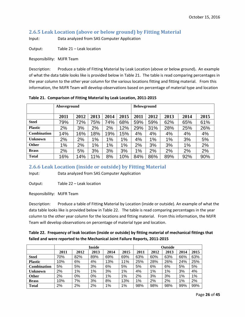
Description: Produce a table of Fitting Material by Leak Location (above or below ground). An example of what the data table looks like is provided below in Table 21. The table is read comparing percentages in the year column to the other year column for the various locations fitting and fitting material. From this information, the MJFR Team will develop observations based on percentage of material type and location
Table 21. Comparison of Fitting Material by Leak Location, 2011-2015
Aboveground Belowground
2011 2012 2013 2014 2015 2011 2012 2013 2014 2015 Steel 79% 72% 75% 74% 68% 59% 59% 62% 65% 61% Plastic 2% 3% 2% 2% 12% 29% 31% 28% 25% 26% Combination 14% 16% 18% 19% 15% 4% 4% 4% 4% 4% Unknown 2% 2% 1% 1% 1% 4% 1% 1% 3% 5% Other 1% 2% 1% 1% 1% 2% 3% 3% 1% 2% Brass 2% 5% 3% 3% 3% 1% 2% 2% 2% 2% Total 16% 14% 11% 8% 10% 84% 86% 89% 92% 90%
2.6.6 Leak Location (inside or outside) by Fitting Material Input: Data analyzed from SAS Computer Application
Output: Table 22 – Leak location
Responsibility: MJFR Team
Description: Produce a table of Fitting Material by Location (inside or outside). An example of what the data table looks like is provided below in Table 22. The table is read comparing percentages in the year column to the other year column for the locations and fitting material. From this information, the MJFR Team will develop observations on percentage of material type and location.
Table 22. Frequency of leak location (inside or outside) by fitting material of mechanical fittings that failed and were reported to the Mechanical Joint Failure Reports, 2011-2015
Inside Outside 2011 2012 2013 2014 2015 2011 2012 2013 2014 2015 Steel 70% 82% 89% 69% 69% 63% 60% 63% 66% 63% Plastic 10% 6% 4% 13% 11% 25% 28% 26% 24% 25% Combination 5% 5% 3% 6% 5% 5% 6% 6% 5% 5% Unknown 2% 1% 1% 3% 1% 4% 1% 1% 3% 4% Other 2% 0% 0% 1% 1% 2% 3% 3% 1% 1% Brass 10% 7% 3% 8% 13% 1% 2% 2% 1% 2% Total 2% 2% 2% 1% 1% 98% 98% 98% 99% 99%
October 15, 2016
Page 27 of 45
2.6.7 Leak Location (main and service connection) by Fitting Material Input: Data analyzed from SAS Computer Application
Output: Table 23 - Frequency of leak location (main or service connection) by fitting material
Responsibility: MJFR Team
Description: Produce a table of Fitting Material by Location (main and service connections). An example of what the data table looks like is provided below in Table 23. The table is read comparing percentages in the year column to the other year column for the various locations and fitting material. From this information, the MJFR Team will develop observations based on percentage of material type and location.
Table 23. Frequency of leak location (main or service connection) by fitting material of mechanical fittings that failed and were reported to the Mechanical Joint Failure Reports, 2012-2015
Main to Main Main to Service Meter Set Service to Service
2012 2013 2014 2015 2012 2013 2014 2015 2012 2013 2014 2015 2012 2013 2014 2015 Steel 79% 77% 88% 75% 62% 67% 61% 66% 70% 70% 69% 60% 54% 58% 58% 57% Plastic 7% 6% 4% 4% 26% 26% 27% 24% 3% 2% 5% 11% 37% 33% 32% 33% Combo 2% 2% 1% 3% 5% 3% 4% 5% 19% 24% 23% 27% 5% 5% 4% 4% Unknown 1% 2% 6% 15% 3% 2% 5% 2% 2% 1% 1% 1% 1% 1% 2% 1% Other 11% 13% 1% 1% 1% 2% 2% 3% 1% 0% 1% 1% 1% 1% 1% 2% Brass 1% 1% 1% 1% 2% 1% 1% 1% 4% 2% 1% 2% 2% 2% 3% 2% Total 15% 17% 21% 20% 13% 12% 12% 11% 10% 8% 6% 6% 62% 63% 60% 62%
2.7 Manufacturer of Fitting Special note for this section: The section is based on the name of manufacturer associated with the MFF as reported by the operator. PHMSA cautions users of this data analysis on potential data quality issues that may exist with the information reported and the need to consider the information in the appropriate context (e.g., amount of fittings that may be in service, length of time a manufacturer may have been producing fittings, and amount of fittings a manufacturer may produce (i.e. overall market share)). PHMSA conducted some additional conservative data analysis in an attempt to improve the data quality mostly due to spelling errors. These tables are based on the frequency of reporting. There is no information available about the number fitting various manufactures produced and sold. Therefore, PHMSA is unable to adjust the failure reports by the quantity in use. The best measure PHMSA is able to use to put the information into context based on other information reported is rate of hazardous leaks eliminated/repaired. The rate of hazardous leaks repaired involving a mechanical fitting for 2015 is the number of MJFR (12,854) divided by the total number of hazardous leaks reported as eliminated/repaired in 2015 (213,684) which is 6.0%. For additional information specific to a certain manufacturer to help put numbers in better context such as amount fittings they may have produced or sold, users may contact the manufacturer. Manufacturers would not be able to provide information on amount of fittings they’ve sold that were actually installed, as that is information the operators would have.
October 15, 2016
Page 28 of 45
Table 24. Quantification of the Role of Mechanical Joints in Hazardous Leaks, Mechanical Joint Failure Reports, 2011-2015
2011 2012 2013 2014 2015 Total Number of MJFR submitted 8,342 7,607 9,920 11,718 12,855 50,442 Hazardous Leaks eliminated/repaired 192,011 187,416 191,129 206,067 213,684 990,307
% MJFR of Total Hazardous Leaks eliminated/repaired 4.30 4.10 5.20 5.70 6.00 5.50
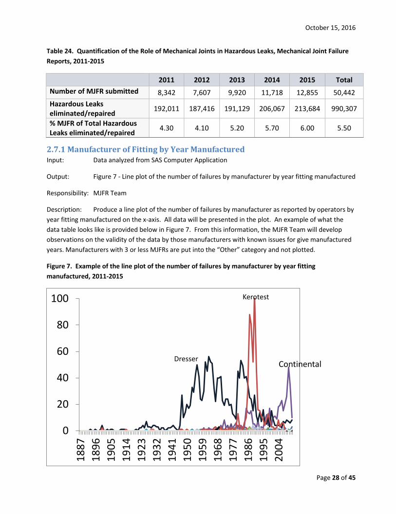
2.7.1 Manufacturer of Fitting by Year Manufactured Input: Data analyzed from SAS Computer Application
Output: Figure 7 - Line plot of the number of failures by manufacturer by year fitting manufactured
Responsibility: MJFR Team
Description: Produce a line plot of the number of failures by manufacturer as reported by operators by year fitting manufactured on the x-axis. All data will be presented in the plot. An example of what the data table looks like is provided below in Figure 7. From this information, the MJFR Team will develop observations on the validity of the data by those manufacturers with known issues for give manufactured years. Manufacturers with 3 or less MJFRs are put into the “Other” category and not plotted.
Figure 7. Example of the line plot of the number of failures by manufacturer by year fitting manufactured, 2011-2015
0
20
40
60
80
100
1887
1896
1905
1914
1923
1932
1941
1950
1959
1968
1977
1986
1995
2004
Dresser Continental
Kerotest
October 15, 2016
Page 29 of 45
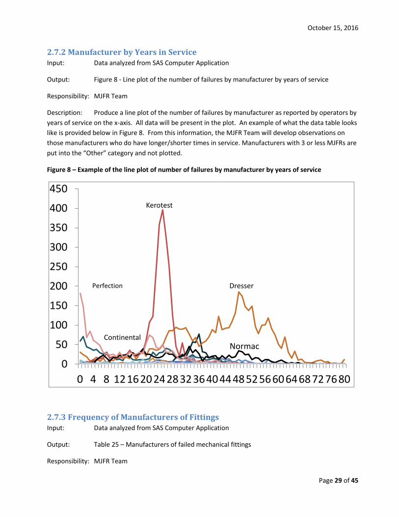
2.7.2 Manufacturer by Years in Service Input: Data analyzed from SAS Computer Application
Output: Figure 8 - Line plot of the number of failures by manufacturer by years of service
Responsibility: MJFR Team
Description: Produce a line plot of the number of failures by manufacturer as reported by operators by years of service on the x-axis. All data will be present in the plot. An example of what the data table looks like is provided below in Figure 8. From this information, the MJFR Team will develop observations on those manufacturers who do have longer/shorter times in service. Manufacturers with 3 or less MJFRs are put into the “Other” category and not plotted.
Figure 8 – Example of the line plot of number of failures by manufacturer by years of service
2.7.3 Frequency of Manufacturers of Fittings Input: Data analyzed from SAS Computer Application
Output: Table 25 – Manufacturers of failed mechanical fittings
Responsibility: MJFR Team
0
50
100
150
200
250
300
350
400
450
0 4 8 121620242832364044485256606468727680
Perfection Dresser
Continental
Kerotest
Normac
October 15, 2016
Page 30 of 45
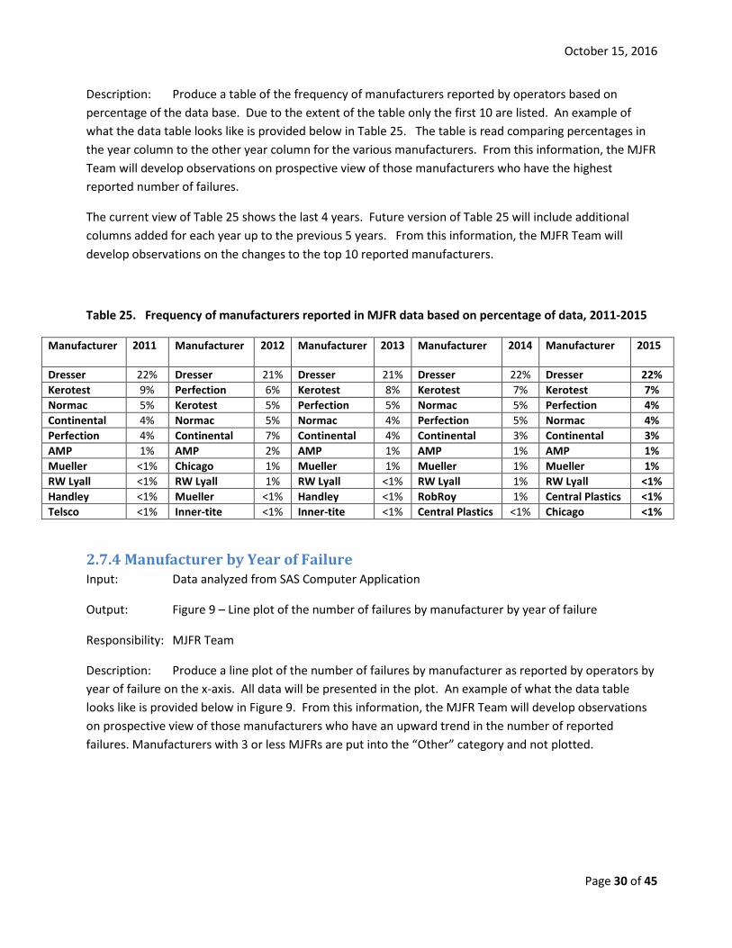
Description: Produce a table of the frequency of manufacturers reported by operators based on percentage of the data base. Due to the extent of the table only the first 10 are listed. An example of what the data table looks like is provided below in Table 25. The table is read comparing percentages in the year column to the other year column for the various manufacturers. From this information, the MJFR Team will develop observations on prospective view of those manufacturers who have the highest reported number of failures.
The current view of Table 25 shows the last 4 years. Future version of Table 25 will include additional columns added for each year up to the previous 5 years. From this information, the MJFR Team will develop observations on the changes to the top 10 reported manufacturers.
Table 25. Frequency of manufacturers reported in MJFR data based on percentage of data, 2011-2015
Manufacturer 2011 Manufacturer 2012 Manufacturer 2013 Manufacturer 2014 Manufacturer 2015
Dresser 22% Dresser 21% Dresser 21% Dresser 22% Dresser 22% Kerotest 9% Perfection 6% Kerotest 8% Kerotest 7% Kerotest 7% Normac 5% Kerotest 5% Perfection 5% Normac 5% Perfection 4% Continental 4% Normac 5% Normac 4% Perfection 5% Normac 4% Perfection 4% Continental 7% Continental 4% Continental 3% Continental 3% AMP 1% AMP 2% AMP 1% AMP 1% AMP 1% Mueller <1% Chicago 1% Mueller 1% Mueller 1% Mueller 1% RW Lyall <1% RW Lyall 1% RW Lyall <1% RW Lyall 1% RW Lyall <1% Handley <1% Mueller <1% Handley <1% RobRoy 1% Central Plastics <1% Telsco <1% Inner-tite <1% Inner-tite <1% Central Plastics <1% Chicago <1%
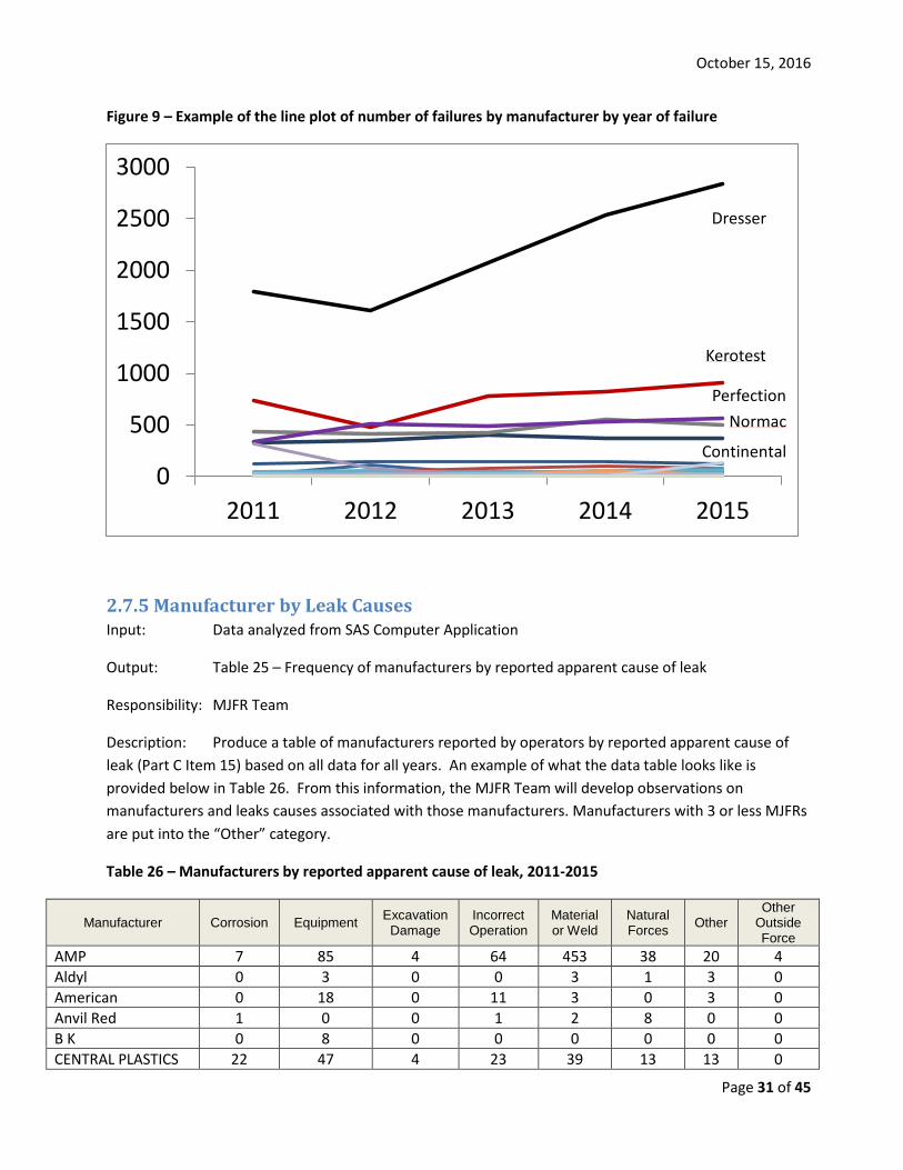
2.7.4 Manufacturer by Year of Failure Input: Data analyzed from SAS Computer Application
Output: Figure 9 – Line plot of the number of failures by manufacturer by year of failure
Responsibility: MJFR Team
Description: Produce a line plot of the number of failures by manufacturer as reported by operators by year of failure on the x-axis. All data will be presented in the plot. An example of what the data table looks like is provided below in Figure 9. From this information, the MJFR Team will develop observations on prospective view of those manufacturers who have an upward trend in the number of reported failures. Manufacturers with 3 or less MJFRs are put into the “Other” category and not plotted.
October 15, 2016
Page 31 of 45
Figure 9 – Example of the line plot of number of failures by manufacturer by year of failure
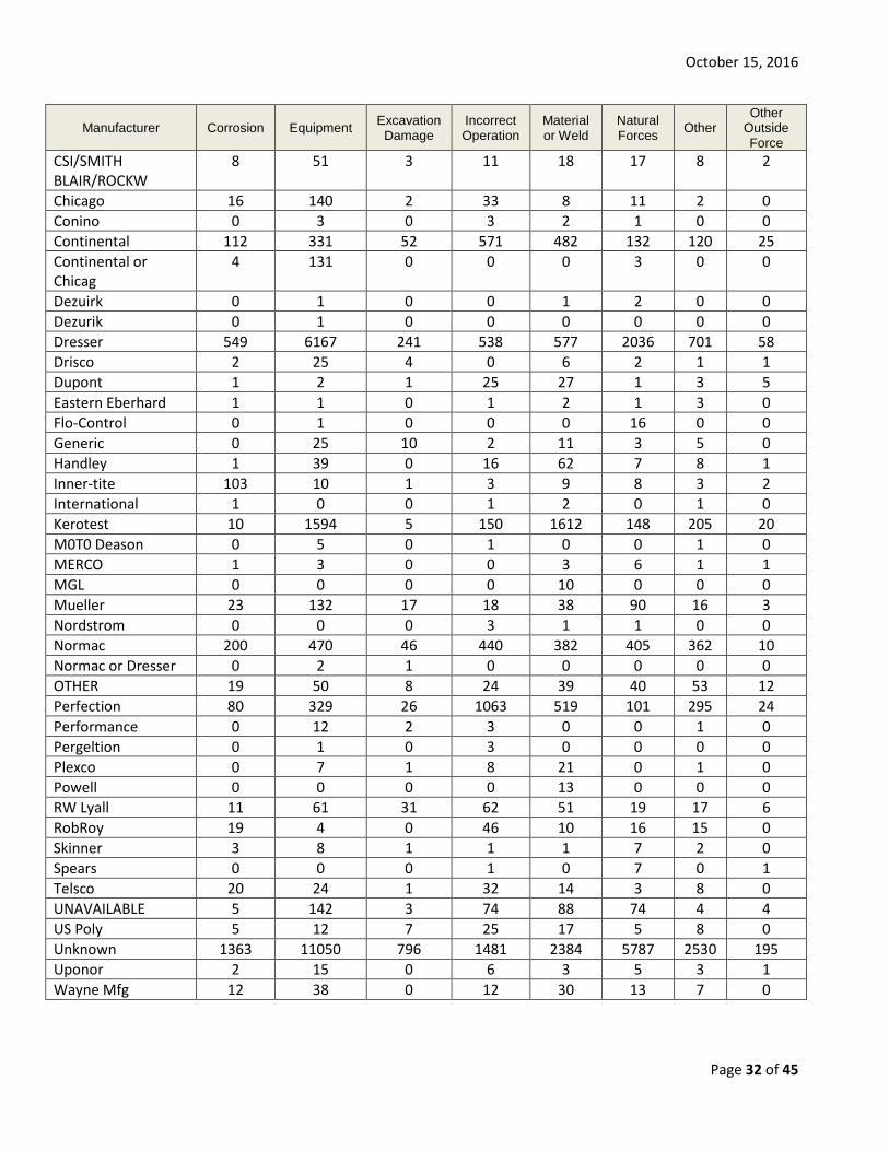
2.7.5 Manufacturer by Leak Causes Input: Data analyzed from SAS Computer Application
Output: Table 25 – Frequency of manufacturers by reported apparent cause of leak
Responsibility: MJFR Team
Description: Produce a table of manufacturers reported by operators by reported apparent cause of leak (Part C Item 15) based on all data for all years. An example of what the data table looks like is provided below in Table 26. From this information, the MJFR Team will develop observations on manufacturers and leaks causes associated with those manufacturers. Manufacturers with 3 or less MJFRs are put into the “Other” category.
Table 26 – Manufacturers by reported apparent cause of leak, 2011-2015
Manufacturer Corrosion Equipment Excavation Damage
Incorrect Operation
Material or Weld
Natural Forces Other
Other Outside Force
AMP 7 85 4 64 453 38 20 4 Aldyl 0 3 0 0 3 1 3 0 American 0 18 0 11 3 0 3 0 Anvil Red 1 0 0 1 2 8 0 0 B K 0 8 0 0 0 0 0 0 CENTRAL PLASTICS 22 47 4 23 39 13 13 0
0
500
1000
1500
2000
2500
3000
2011 2012 2013 2014 2015
Kerotest
Normac Perfection
Continental
Dresser
October 15, 2016
Page 32 of 45
Manufacturer Corrosion Equipment Excavation Damage
Incorrect Operation
Material or Weld
Natural Forces Other
Other Outside Force
CSI/SMITH BLAIR/ROCKW
8 51 3 11 18 17 8 2
Chicago 16 140 2 33 8 11 2 0 Conino 0 3 0 3 2 1 0 0 Continental 112 331 52 571 482 132 120 25 Continental or Chicag
4 131 0 0 0 3 0 0
Dezuirk 0 1 0 0 1 2 0 0 Dezurik 0 1 0 0 0 0 0 0 Dresser 549 6167 241 538 577 2036 701 58 Drisco 2 25 4 0 6 2 1 1 Dupont 1 2 1 25 27 1 3 5 Eastern Eberhard 1 1 0 1 2 1 3 0 Flo-Control 0 1 0 0 0 16 0 0 Generic 0 25 10 2 11 3 5 0 Handley 1 39 0 16 62 7 8 1 Inner-tite 103 10 1 3 9 8 3 2 International 1 0 0 1 2 0 1 0 Kerotest 10 1594 5 150 1612 148 205 20 M0T0 Deason 0 5 0 1 0 0 1 0 MERCO 1 3 0 0 3 6 1 1 MGL 0 0 0 0 10 0 0 0 Mueller 23 132 17 18 38 90 16 3 Nordstrom 0 0 0 3 1 1 0 0 Normac 200 470 46 440 382 405 362 10 Normac or Dresser 0 2 1 0 0 0 0 0 OTHER 19 50 8 24 39 40 53 12 Perfection 80 329 26 1063 519 101 295 24 Performance 0 12 2 3 0 0 1 0 Pergeltion 0 1 0 3 0 0 0 0 Plexco 0 7 1 8 21 0 1 0 Powell 0 0 0 0 13 0 0 0 RW Lyall 11 61 31 62 51 19 17 6 RobRoy 19 4 0 46 10 16 15 0 Skinner 3 8 1 1 1 7 2 0 Spears 0 0 0 1 0 7 0 1 Telsco 20 24 1 32 14 3 8 0 UNAVAILABLE 5 142 3 74 88 74 4 4 US Poly 5 12 7 25 17 5 8 0 Unknown 1363 11050 796 1481 2384 5787 2530 195 Uponor 2 15 0 6 3 5 3 1 Wayne Mfg 12 38 0 12 30 13 7 0
October 15, 2016
Page 33 of 45
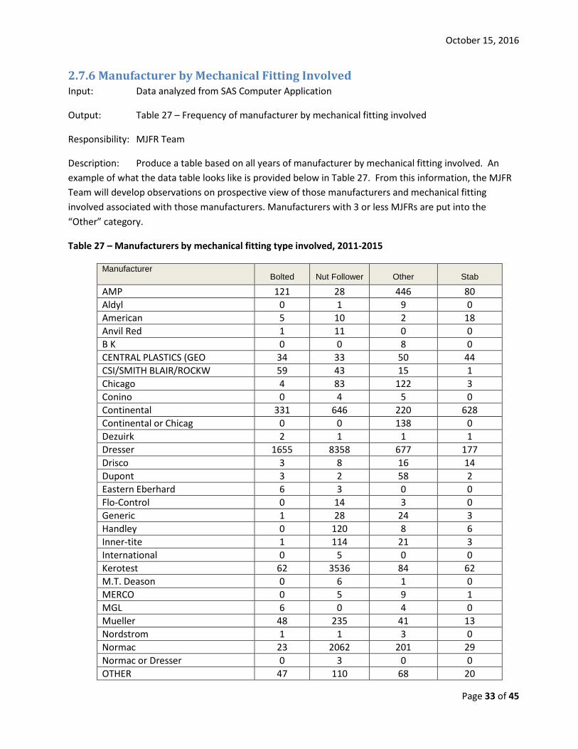
2.7.6 Manufacturer by Mechanical Fitting Involved Input: Data analyzed from SAS Computer Application
Output: Table 27 – Frequency of manufacturer by mechanical fitting involved
Responsibility: MJFR Team
Description: Produce a table based on all years of manufacturer by mechanical fitting involved. An example of what the data table looks like is provided below in Table 27. From this information, the MJFR Team will develop observations on prospective view of those manufacturers and mechanical fitting involved associated with those manufacturers. Manufacturers with 3 or less MJFRs are put into the “Other” category.
Table 27 – Manufacturers by mechanical fitting type involved, 2011-2015
Manufacturer Bolted Nut Follower Other Stab
AMP 121 28 446 80 Aldyl 0 1 9 0 American 5 10 2 18 Anvil Red 1 11 0 0 B K 0 0 8 0 CENTRAL PLASTICS (GEO 34 33 50 44 CSI/SMITH BLAIR/ROCKW 59 43 15 1 Chicago 4 83 122 3 Conino 0 4 5 0 Continental 331 646 220 628 Continental or Chicag 0 0 138 0 Dezuirk 2 1 1 1 Dresser 1655 8358 677 177 Drisco 3 8 16 14 Dupont 3 2 58 2 Eastern Eberhard 6 3 0 0 Flo-Control 0 14 3 0 Generic 1 28 24 3 Handley 0 120 8 6 Inner-tite 1 114 21 3 International 0 5 0 0 Kerotest 62 3536 84 62 M.T. Deason 0 6 1 0 MERCO 0 5 9 1 MGL 6 0 4 0 Mueller 48 235 41 13 Nordstrom 1 1 3 0 Normac 23 2062 201 29 Normac or Dresser 0 3 0 0 OTHER 47 110 68 20
October 15, 2016
Page 34 of 45
Manufacturer Bolted Nut Follower Other Stab
Perfection 105 70 213 2049 Performance 0 1 5 12 Pergeltion 0 0 0 4 Plexco 1 10 13 14 Powell 0 13 0 0 RW Lyall 70 32 79 77 RobRoy 0 68 37 5 Skinner 17 5 1 0 Spears 0 9 0 0 Telsco 2 95 4 1 UNAVAILABLE 13 235 80 66 US Poly 2 4 51 22 Unk 3076 14471 5975 2064 Uponor 1 15 14 5 Wayne Mfg 0 81 21 10
2.8 Operators submitting MJFR The MJFR Team members will analyze the MJFR data and generate the tables and charts outlined in this procedure. Typically the data from PDM is moved into a computer application called “SAS” in which the data is manipulated for analysis. The output from SAS is moved into PowerPoint for presentation and discussion purposes. The most current data is available on the public and internal sides of the PDM. Other evaluations and analyses may be performed depending upon the trends in the data. For instance, the MJFR Team may decide to evaluate the number of MJFR by mile of main or service that an Operator is reporting and on an individual operator basis, as appropriate.
Similar to information provided by manufacturer, PHMSA cautions users of this data analysis on the need to consider the information in the appropriate context (e.g., amount and type of fittings an operator may have in their systems, system mileage, etc.). There is no definitive information publicly available about the number of fittings produced or installed. Many operators do maintain an inventory tracking system of the amount of fittings that may have purchased vs. in stock vs. installed, but numbers can vary. Therefore, PHMSA is unable to adjust the failure reports by the quantity produced or in use. For additional information specific to a certain operator to help put numbers in better context, users are encouraged to contact the operator.
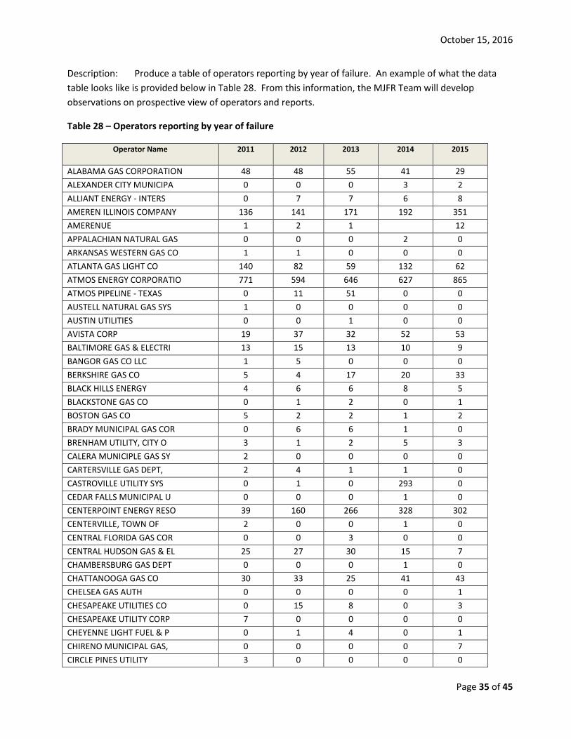
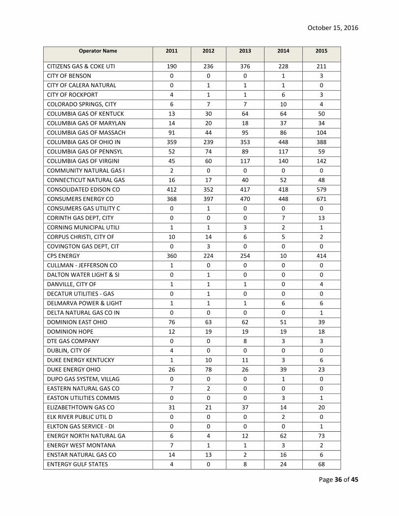
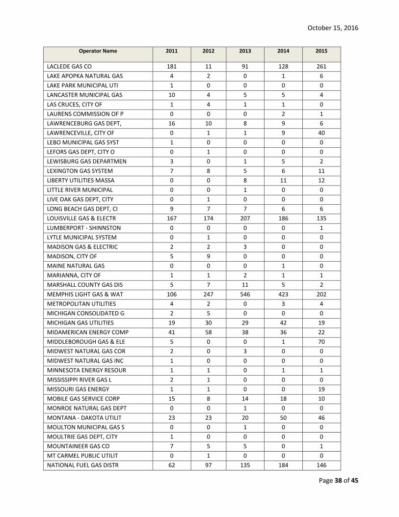
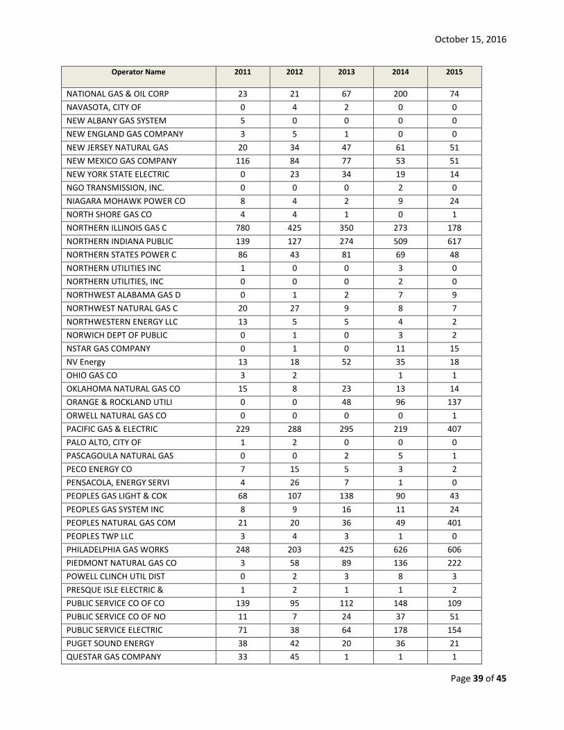
2.8.1 Frequency of Operator by Year of Failure Input: Data analyzed from SAS Computer Application
Output: Table 28 – Frequency of operators reporting fitting failures by year of failure
Responsibility: MJFR Team
October 15, 2016
Page 35 of 45
Description: Produce a table of operators reporting by year of failure. An example of what the data table looks like is provided below in Table 28. From this information, the MJFR Team will develop observations on prospective view of operators and reports.
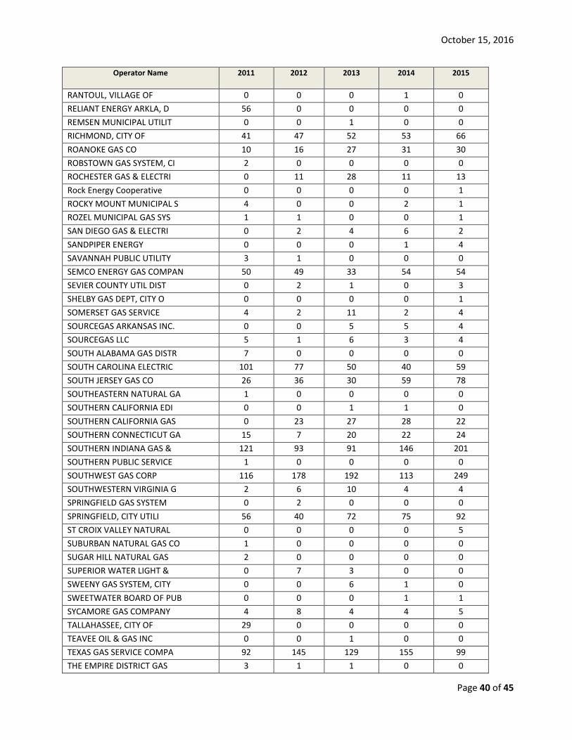
Table 28 – Operators reporting by year of failure
Operator Name 2011 2012 2013 2014 2015
ALABAMA GAS CORPORATION 48 48 55 41 29 ALEXANDER CITY MUNICIPA 0 0 0 3 2 ALLIANT ENERGY - INTERS 0 7 7 6 8 AMEREN ILLINOIS COMPANY 136 141 171 192 351 AMERENUE 1 2 1 12 APPALACHIAN NATURAL GAS 0 0 0 2 0 ARKANSAS WESTERN GAS CO 1 1 0 0 0 ATLANTA GAS LIGHT CO 140 82 59 132 62 ATMOS ENERGY CORPORATIO 771 594 646 627 865 ATMOS PIPELINE - TEXAS 0 11 51 0 0 AUSTELL NATURAL GAS SYS 1 0 0 0 0 AUSTIN UTILITIES 0 0 1 0 0 AVISTA CORP 19 37 32 52 53 BALTIMORE GAS & ELECTRI 13 15 13 10 9 BANGOR GAS CO LLC 1 5 0 0 0 BERKSHIRE GAS CO 5 4 17 20 33 BLACK HILLS ENERGY 4 6 6 8 5 BLACKSTONE GAS CO 0 1 2 0 1 BOSTON GAS CO 5 2 2 1 2 BRADY MUNICIPAL GAS COR 0 6 6 1 0 BRENHAM UTILITY, CITY O 3 1 2 5 3 CALERA MUNICIPLE GAS SY 2 0 0 0 0 CARTERSVILLE GAS DEPT, 2 4 1 1 0 CASTROVILLE UTILITY SYS 0 1 0 293 0 CEDAR FALLS MUNICIPAL U 0 0 0 1 0 CENTERPOINT ENERGY RESO 39 160 266 328 302 CENTERVILLE, TOWN OF 2 0 0 1 0 CENTRAL FLORIDA GAS COR 0 0 3 0 0 CENTRAL HUDSON GAS & EL 25 27 30 15 7 CHAMBERSBURG GAS DEPT 0 0 0 1 0 CHATTANOOGA GAS CO 30 33 25 41 43 CHELSEA GAS AUTH 0 0 0 0 1 CHESAPEAKE UTILITIES CO 0 15 8 0 3 CHESAPEAKE UTILITY CORP 7 0 0 0 0 CHEYENNE LIGHT FUEL & P 0 1 4 0 1 CHIRENO MUNICIPAL GAS, 0 0 0 0 7 CIRCLE PINES UTILITY 3 0 0 0 0
October 15, 2016
Page 36 of 45
Operator Name 2011 2012 2013 2014 2015
CITIZENS GAS & COKE UTI 190 236 376 228 211 CITY OF BENSON 0 0 0 1 3 CITY OF CALERA NATURAL 0 1 1 1 0 CITY OF ROCKPORT 4 1 1 6 3 COLORADO SPRINGS, CITY 6 7 7 10 4 COLUMBIA GAS OF KENTUCK 13 30 64 64 50 COLUMBIA GAS OF MARYLAN 14 20 18 37 34 COLUMBIA GAS OF MASSACH 91 44 95 86 104 COLUMBIA GAS OF OHIO IN 359 239 353 448 388 COLUMBIA GAS OF PENNSYL 52 74 89 117 59 COLUMBIA GAS OF VIRGINI 45 60 117 140 142 COMMUNITY NATURAL GAS I 2 0 0 0 0 CONNECTICUT NATURAL GAS 16 17 40 52 48 CONSOLIDATED EDISON CO 412 352 417 418 579 CONSUMERS ENERGY CO 368 397 470 448 671 CONSUMERS GAS UTILITY C 0 1 0 0 0 CORINTH GAS DEPT, CITY 0 0 0 7 13 CORNING MUNICIPAL UTILI 1 1 3 2 1 CORPUS CHRISTI, CITY OF 10 14 6 5 2 COVINGTON GAS DEPT, CIT 0 3 0 0 0 CPS ENERGY 360 224 254 10 414 CULLMAN - JEFFERSON CO 1 0 0 0 0 DALTON WATER LIGHT & SI 0 1 0 0 0 DANVILLE, CITY OF 1 1 1 0 4 DECATUR UTILITIES - GAS 0 1 0 0 0 DELMARVA POWER & LIGHT 1 1 1 6 6 DELTA NATURAL GAS CO IN 0 0 0 0 1 DOMINION EAST OHIO 76 63 62 51 39 DOMINION HOPE 12 19 19 19 18 DTE GAS COMPANY 0 0 8 3 3 DUBLIN, CITY OF 4 0 0 0 0 DUKE ENERGY KENTUCKY 1 10 11 3 6 DUKE ENERGY OHIO 26 78 26 39 23 DUPO GAS SYSTEM, VILLAG 0 0 0 1 0 EASTERN NATURAL GAS CO 7 2 0 0 0 EASTON UTILITIES COMMIS 0 0 0 3 1 ELIZABETHTOWN GAS CO 31 21 37 14 20 ELK RIVER PUBLIC UTIL D 0 0 0 2 0 ELKTON GAS SERVICE - DI 0 0 0 0 1 ENERGY NORTH NATURAL GA 6 4 12 62 73 ENERGY WEST MONTANA 7 1 1 3 2 ENSTAR NATURAL GAS CO 14 13 2 16 6 ENTERGY GULF STATES 4 0 8 24 68

October 15, 2016
Page 37 of 45
Operator Name 2011 2012 2013 2014 2015
ENTERGY NEW ORLEANS, IN 3 5 3 6 7 ENTEX, A NORAM ENERGY C 198 45 0 0 0 EQUITABLE GAS COMPANY, 0 17 32 0 0 EQUITABLE RESOURCES (A. 10 0 0 0 0 ESSEX COUNTY GAS CO 0 2 0 0 0 FAIRBANKS NATURAL GAS 0 0 0 1 0 FAIRFIELD MUNICIPAL GAS 2 1 0 0 0 FAIRHOPE GAS SYSTEM, CI 0 1 0 0 0 FALFURRIAS UTILITY BOAR 0 18 6 43 11 FALLS CITY UTILITIES 0 1 0 0 0 FAYETTEVILLE PUBLIC UTI 0 0 2 0 0 FITCHBURG GAS & ELECTRI 2 9 18 10 9 FLORENCE GAS DEPT, CITY 3 1 0 0 0 FLORIDA CITY GAS 1 0 0 0 2 FLORIDA PUBLIC UTILITIE 6 10 7 6 10 FORT HILL NATURAL GAS A 0 0 0 0 5 GAINESVILLE REGIONAL UT 1 0 0 0 0 GREAT PLAINS NATURAL GA 4 1 0 0 2 GREATER MINNESOTA GAS I 0 0 0 0 1 GREENVILLE UTILITIES CO 2 1 9 3 7 GREENWOOD COMMISSION OF 2 9 2 2 3 GUYMON MUNICIPAL GAS CO 0 1 0 0 0 HALLS GAS DEPT, TOWN OF 1 0 0 0 0 HALSTEAD GAS DEPT, CITY 0 1 0 0 0 HAMILTON GAS DEPT, CITY 8 8 10 1 2 HASTINGS UTILITIES 2 0 0 0 1 HAWAI`IGAS 0 0 11 29 1 HAWAII GAS 0 0 0 0 1 HAWARDEN GAS DEPT, CITY 1 2 2 1 0 HOLYOKE GAS & ELECTRIC 0 1 9 16 14 HUMBOLDT UTILITIES - GA 13 17 9 4 7 HUNTSVILLE GAS SYSTEM 13 9 13 15 26 INDIANA GAS CO INC 87 66 61 95 97 INDIANA NATURAL GAS COR 0 0 0 0 1 INTERMOUNTAIN GAS CO 9 4 3 9 10 JACKSON ENERGY AUTHORIT 44 19 31 13 10 KANSAS GAS SERVICE 89 68 62 0 0 KANSAS GAS SERVICE COMP 0 8 18 90 110 KEYSPAN ENERGY DELIVERY 1 0 0 0 0 KEYSTONE RURAL GAS DIST 2 1 2 0 0 KINGS MOUNTAIN NATURAL 0 0 0 2 0 KNG ENERGY INC 2 0 0 1 4 KNOXVILLE UTILITIES BOA 6 7 12 16 11
October 15, 2016
Page 38 of 45
Operator Name 2011 2012 2013 2014 2015
LACLEDE GAS CO 181 11 91 128 261 LAKE APOPKA NATURAL GAS 4 2 0 1 6 LAKE PARK MUNICIPAL UTI 1 0 0 0 0 LANCASTER MUNICIPAL GAS 10 4 5 5 4 LAS CRUCES, CITY OF 1 4 1 1 0 LAURENS COMMISSION OF P 0 0 0 2 1 LAWRENCEBURG GAS DEPT, 16 10 8 9 6 LAWRENCEVILLE, CITY OF 0 1 1 9 40 LEBO MUNICIPAL GAS SYST 1 0 0 0 0 LEFORS GAS DEPT, CITY O 0 1 0 0 0 LEWISBURG GAS DEPARTMEN 3 0 1 5 2 LEXINGTON GAS SYSTEM 7 8 5 6 11 LIBERTY UTILITIES MASSA 0 0 8 11 12 LITTLE RIVER MUNICIPAL 0 0 1 0 0 LIVE OAK GAS DEPT, CITY 0 1 0 0 0 LONG BEACH GAS DEPT, CI 9 7 7 6 6 LOUISVILLE GAS & ELECTR 167 174 207 186 135 LUMBERPORT - SHINNSTON 0 0 0 0 1 LYTLE MUNICIPAL SYSTEM 0 1 0 0 0 MADISON GAS & ELECTRIC 2 2 3 0 0 MADISON, CITY OF 5 9 0 0 0 MAINE NATURAL GAS 0 0 0 1 0 MARIANNA, CITY OF 1 1 2 1 1 MARSHALL COUNTY GAS DIS 5 7 11 5 2 MEMPHIS LIGHT GAS & WAT 106 247 546 423 202 METROPOLITAN UTILITIES 4 2 0 3 4 MICHIGAN CONSOLIDATED G 2 5 0 0 0 MICHIGAN GAS UTILITIES 19 30 29 42 19 MIDAMERICAN ENERGY COMP 41 58 38 36 22 MIDDLEBOROUGH GAS & ELE 5 0 0 1 70 MIDWEST NATURAL GAS COR 2 0 3 0 0 MIDWEST NATURAL GAS INC 1 0 0 0 0 MINNESOTA ENERGY RESOUR 1 1 0 1 1 MISSISSIPPI RIVER GAS L 2 1 0 0 0 MISSOURI GAS ENERGY 1 1 0 0 19 MOBILE GAS SERVICE CORP 15 8 14 18 10 MONROE NATURAL GAS DEPT 0 0 1 0 0 MONTANA - DAKOTA UTILIT 23 23 20 50 46 MOULTON MUNICIPAL GAS S 0 0 1 0 0 MOULTRIE GAS DEPT, CITY 1 0 0 0 0 MOUNTAINEER GAS CO 7 5 5 0 1 MT CARMEL PUBLIC UTILIT 0 1 0 0 0 NATIONAL FUEL GAS DISTR 62 97 135 184 146
October 15, 2016
Page 39 of 45
Operator Name 2011 2012 2013 2014 2015
NATIONAL GAS & OIL CORP 23 21 67 200 74 NAVASOTA, CITY OF 0 4 2 0 0 NEW ALBANY GAS SYSTEM 5 0 0 0 0 NEW ENGLAND GAS COMPANY 3 5 1 0 0 NEW JERSEY NATURAL GAS 20 34 47 61 51 NEW MEXICO GAS COMPANY 116 84 77 53 51 NEW YORK STATE ELECTRIC 0 23 34 19 14 NGO TRANSMISSION, INC. 0 0 0 2 0 NIAGARA MOHAWK POWER CO 8 4 2 9 24 NORTH SHORE GAS CO 4 4 1 0 1 NORTHERN ILLINOIS GAS C 780 425 350 273 178 NORTHERN INDIANA PUBLIC 139 127 274 509 617 NORTHERN STATES POWER C 86 43 81 69 48 NORTHERN UTILITIES INC 1 0 0 3 0 NORTHERN UTILITIES, INC 0 0 0 2 0 NORTHWEST ALABAMA GAS D 0 1 2 7 9 NORTHWEST NATURAL GAS C 20 27 9 8 7 NORTHWESTERN ENERGY LLC 13 5 5 4 2 NORWICH DEPT OF PUBLIC 0 1 0 3 2 NSTAR GAS COMPANY 0 1 0 11 15 NV Energy 13 18 52 35 18 OHIO GAS CO 3 2 1 1 OKLAHOMA NATURAL GAS CO 15 8 23 13 14 ORANGE & ROCKLAND UTILI 0 0 48 96 137 ORWELL NATURAL GAS CO 0 0 0 0 1 PACIFIC GAS & ELECTRIC 229 288 295 219 407 PALO ALTO, CITY OF 1 2 0 0 0 PASCAGOULA NATURAL GAS 0 0 2 5 1 PECO ENERGY CO 7 15 5 3 2 PENSACOLA, ENERGY SERVI 4 26 7 1 0 PEOPLES GAS LIGHT & COK 68 107 138 90 43 PEOPLES GAS SYSTEM INC 8 9 16 11 24 PEOPLES NATURAL GAS COM 21 20 36 49 401 PEOPLES TWP LLC 3 4 3 1 0 PHILADELPHIA GAS WORKS 248 203 425 626 606 PIEDMONT NATURAL GAS CO 3 58 89 136 222 POWELL CLINCH UTIL DIST 0 2 3 8 3 PRESQUE ISLE ELECTRIC & 1 2 1 1 2 PUBLIC SERVICE CO OF CO 139 95 112 148 109 PUBLIC SERVICE CO OF NO 11 7 24 37 51 PUBLIC SERVICE ELECTRIC 71 38 64 178 154 PUGET SOUND ENERGY 38 42 20 36 21 QUESTAR GAS COMPANY 33 45 1 1 1
October 15, 2016
Page 40 of 45
Operator Name 2011 2012 2013 2014 2015
RANTOUL, VILLAGE OF 0 0 0 1 0 RELIANT ENERGY ARKLA, D 56 0 0 0 0 REMSEN MUNICIPAL UTILIT 0 0 1 0 0 RICHMOND, CITY OF 41 47 52 53 66 ROANOKE GAS CO 10 16 27 31 30 ROBSTOWN GAS SYSTEM, CI 2 0 0 0 0 ROCHESTER GAS & ELECTRI 0 11 28 11 13 Rock Energy Cooperative 0 0 0 0 1 ROCKY MOUNT MUNICIPAL S 4 0 0 2 1 ROZEL MUNICIPAL GAS SYS 1 1 0 0 1 SAN DIEGO GAS & ELECTRI 0 2 4 6 2 SANDPIPER ENERGY 0 0 0 1 4 SAVANNAH PUBLIC UTILITY 3 1 0 0 0 SEMCO ENERGY GAS COMPAN 50 49 33 54 54 SEVIER COUNTY UTIL DIST 0 2 1 0 3 SHELBY GAS DEPT, CITY O 0 0 0 0 1 SOMERSET GAS SERVICE 4 2 11 2 4 SOURCEGAS ARKANSAS INC. 0 0 5 5 4 SOURCEGAS LLC 5 1 6 3 4 SOUTH ALABAMA GAS DISTR 7 0 0 0 0 SOUTH CAROLINA ELECTRIC 101 77 50 40 59 SOUTH JERSEY GAS CO 26 36 30 59 78 SOUTHEASTERN NATURAL GA 1 0 0 0 0 SOUTHERN CALIFORNIA EDI 0 0 1 1 0 SOUTHERN CALIFORNIA GAS 0 23 27 28 22 SOUTHERN CONNECTICUT GA 15 7 20 22 24 SOUTHERN INDIANA GAS & 121 93 91 146 201 SOUTHERN PUBLIC SERVICE 1 0 0 0 0 SOUTHWEST GAS CORP 116 178 192 113 249 SOUTHWESTERN VIRGINIA G 2 6 10 4 4 SPRINGFIELD GAS SYSTEM 0 2 0 0 0 SPRINGFIELD, CITY UTILI 56 40 72 75 92 ST CROIX VALLEY NATURAL 0 0 0 0 5 SUBURBAN NATURAL GAS CO 1 0 0 0 0 SUGAR HILL NATURAL GAS 2 0 0 0 0 SUPERIOR WATER LIGHT & 0 7 3 0 0 SWEENY GAS SYSTEM, CITY 0 0 6 1 0 SWEETWATER BOARD OF PUB 0 0 0 1 1 SYCAMORE GAS COMPANY 4 8 4 4 5 TALLAHASSEE, CITY OF 29 0 0 0 0 TEAVEE OIL & GAS INC 0 0 1 0 0 TEXAS GAS SERVICE COMPA 92 145 129 155 99 THE EMPIRE DISTRICT GAS 3 1 1 0 0

October 15, 2016
Page 41 of 45
Operator Name 2011 2012 2013 2014 2015
THE GAS COMPANY 16 20 1 0 0 TRUSSVILLE, UTILITIES B 1 5 7 0 0 UGI CENTRAL PENN GAS, I 5 9 1 2 9 UGI PENN NATURAL GAS 199 115 105 152 169 UGI UTILITIES, INC 143 140 209 315 351 UNION OIL & GAS INC 0 1 7 6 1 UNION UTILITY DEPT, CIT 3 0 0 0 1 UNISOURCE ENERGY SERVIC 3 13 12 6 7 VALLEY ENERGY, INC. 2 1 46 40 10 VECTREN ENERGY DELIVERY 44 17 33 70 99 VERMONT GAS SYSTEMS INC 5 16 4 8 19 VILLAGE OF MORTON 1 0 0 0 0 VIRGINIA NATURAL GAS 16 41 116 228 220 WALLER, CITY OF 0 0 1 0 0 WALNUT MUNICIPLE GAS SY 1 2 1 1 1 WASHINGTON GAS LIGHT CO 238 298 471 890 985 WATERTOWN MUNICIPAL GAS 0 0 0 1 0 WATERVILLE GAS & OIL CO 2 1 4 4 2 WE ENERGIES 12 0 0 0 0 WEST POINT GAS SYSTEM 0 0 2 0 0 WEST TEXAS GAS INC 0 0 4 0 1 WILLMUT GAS & OIL CO - 4 3 1 3 3 WILSON GAS DEPT, CITY O 0 11 4 6 11 WISCONSIN ELECTRIC POWE 0 1 0 46 28 WISCONSIN GAS CO 7 0 0 0 0 WISCONSIN GAS LLC DBA W 0 38 219 356 258 WISCONSIN PUBLIC SERVIC 4 4 1 3 0 YANKEE GAS SERVICES CO 140 121 177 231 165 YORK COUNTY NATURAL GAS 0 0 1 0 0
October 15, 2016
Page 42 of 45
3.0 Future Analysis Ideas and Concepts The additional years of data will allow for the application of the appropriate statistics. The format of the tables and figures will need to change over time to accommodate the additional information, and more line plots have been used in this year’s report with 5-years’ worth of data having been collected.
3.1 Limitations Due to the nature of the data some types of analysis cannot be accomplished. For example, some analysis requires multiple years’ worth of information. For surveillance systems, 5 years is the generally accepted minimum. Now that this threshold is met, the MJFR is still a surveillance system, and the information collection activity will continue for another 3 years. The largest limitation facing MJFR is the absent of denominator information. The information of how many and what type of fittings were installed and where the fittings were installed is not available. Another limitation that is common among surveillance systems is issues with the interpretation of the report form itself. The MJFR team has made attempts to edit any potential misunderstandings with the report form and instructions for the report form. Also as with any other surveillance system there is the variance of data quality between reports. An example would be the naming convention of manufacturers from submitted MJFRs with varying manufacturer names describing the same manufacturer. The MJFR Team has mapped names together when appropriate.
3.2 Updates
Data submitted for 2015 shows similar trends to the previous years of data. Tables with aggregated views of data replaced some tables that appeared in last year’s report. These removed tables did not appear to add any additional information that could not be gathered from an aggregate view of the data. At this time no other additional analysis has been identified for inclusion.
In the future, the Team plans on including a historical list of updates or changes to the form, updates to the electronic submittal process, discussion of advisory bulletins pertaining to MJFR, etc.
Rulemaking is in progress to change the name of the Mechanical Fitting Failure Report to Mechanical Joint Failure Report to represent that the hazardous leak occurred within a joint connection of pipe and the apparent cause of leakage may not be due to equipment failure of the fitting.

October 15, 2016
Page 43 of 45
4.0 Technical Review and Analysis Input: Figures, Tables, Data generated from Analysis in Section 2
Output: This procedure with updated tables and figures inserted into the document or other appropriate documentation
Responsibility: MJFR Team
Description: The MJFR Team will meet to discuss the initial analysis, vet out concepts and ideas about what the data analysis represents, and potential additional analysis. The meetings will be held in person and via web-based meeting. Meeting minutes documenting initial observations and recommendations will be distributed for comments and review internally within PHMSA.
Following MJFR Team annual discussions of the data and analysis, observations and recommendations will be documented in an electronic format suitable for transmission and filling. This documentation is typically the completion of this procedural document. Other documentation may include more informal dissemination of information through the DIMP website or presentations and discussion with stakeholders, or if more formal action is needed, a Memorandum, Technical Report, Advisory Bulletin, or email transmission to PHMSA personnel. The analysis should include consideration and discussion of, but not limited to, the following:
• Trends in data analysis • Suspect materials, specific models of mechanical fittings, etc. • Identification of issues that represent a threat to the integrity of the nation’s distribution pipeline
system • Areas of concern identified by the MJFR Team
4.1 Overview of Analysis Analysis of the MJFR data received to date is consistent with what was expected when we initiated this information collection activity and is consistent with other data sources (e.g., data from Gas Distribution annual reports). Data submitted for 2015 shows similar trends to previous 5 years of data collection, and trends in the data are within acceptable variance. In summary, the majority of mechanical joint failures resulting in a hazardous leak involve nut-follower, coupling type fittings. In 2015, data analysis provides the following:
• Equipment failure is the leading reported cause of leaks (42%), and Natural forces is second (18%) • Majority of leaks occur outside (99%), belowground (90%) involving service-to-service connections
(62%) • Steel fittings (62%) are involved the majority of reports, and plastic fittings are second (25%) • Valves are involved in 13% of reported failures in 2015.
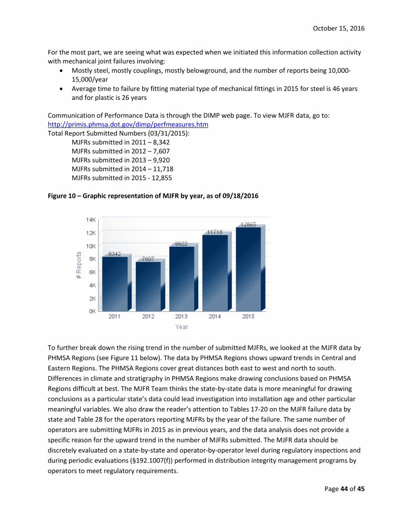
October 15, 2016
Page 44 of 45
For the most part, we are seeing what was expected when we initiated this information collection activity with mechanical joint failures involving:
• Mostly steel, mostly couplings, mostly belowground, and the number of reports being 10,000-15,000/year
• Average time to failure by fitting material type of mechanical fittings in 2015 for steel is 46 years and for plastic is 26 years
Communication of Performance Data is through the DIMP web page. To view MJFR data, go to: http://primis.phmsa.dot.gov/dimp/perfmeasures.htm Total Report Submitted Numbers (03/31/2015):
MJFRs submitted in 2011 – 8,342 MJFRs submitted in 2012 – 7,607 MJFRs submitted in 2013 – 9,920 MJFRs submitted in 2014 – 11,718 MJFRs submitted in 2015 - 12,855
Figure 10 – Graphic representation of MJFR by year, as of 09/18/2016
To further break down the rising trend in the number of submitted MJFRs, we looked at the MJFR data by PHMSA Regions (see Figure 11 below). The data by PHMSA Regions shows upward trends in Central and Eastern Regions. The PHMSA Regions cover great distances both east to west and north to south. Differences in climate and stratigraphy in PHMSA Regions make drawing conclusions based on PHMSA Regions difficult at best. The MJFR Team thinks the state-by-state data is more meaningful for drawing conclusions as a particular state’s data could lead investigation into installation age and other particular meaningful variables. We also draw the reader’s attention to Tables 17-20 on the MJFR failure data by state and Table 28 for the operators reporting MJFRs by the year of the failure. The same number of operators are submitting MJFRs in 2015 as in previous years, and the data analysis does not provide a specific reason for the upward trend in the number of MJFRs submitted. The MJFR data should be discretely evaluated on a state-by-state and operator-by-operator level during regulatory inspections and during periodic evaluations (§192.1007(f)) performed in distribution integrity management programs by operators to meet regulatory requirements.
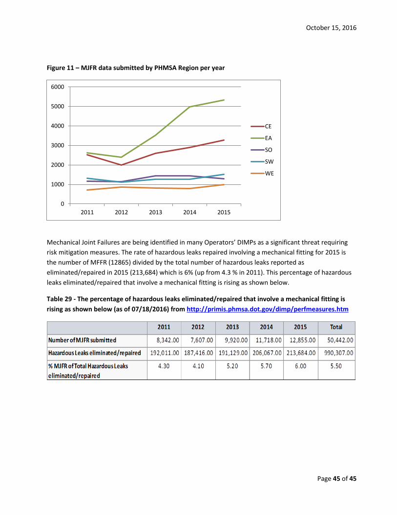
October 15, 2016
Page 45 of 45
Figure 11 – MJFR data submitted by PHMSA Region per year
Mechanical Joint Failures are being identified in many Operators’ DIMPs as a significant threat requiring risk mitigation measures. The rate of hazardous leaks repaired involving a mechanical fitting for 2015 is the number of MFFR (12865) divided by the total number of hazardous leaks reported as eliminated/repaired in 2015 (213,684) which is 6% (up from 4.3 % in 2011). This percentage of hazardous leaks eliminated/repaired that involve a mechanical fitting is rising as shown below.
Table 29 - The percentage of hazardous leaks eliminated/repaired that involve a mechanical fitting is rising as shown below (as of 07/18/2016) from http://primis.phmsa.dot.gov/dimp/perfmeasures.htm
0
1000
2000
3000
4000
5000
6000
2011 2012 2013 2014 2015
CE
EA
SO
SW
WE