Metropolitan Interoperability Radio System - Alexandria ...
46
A program of the National Institute of Justice National Law Enforcement and Corrections Technology Center— Northeast (NLECTC-NE) Rome, NY 13441 Advanced Generation of Interoperability for Law Enforcement (AGILE) Report No. TE-02-03 April 4, 2003 Metropolitan Interoperability Radio System - Alexandria Site Description Document
Transcript of Metropolitan Interoperability Radio System - Alexandria ...

A program of the National Institute of Justice
National Law Enforcement and Corrections Technology Center— Northeast (NLECTC-NE)
Rome, NY 13441
Advanced Generation of Interoperability for Law Enforcement (AGILE)
Report No. TE-02-03
April 4, 2003
Metropolitan Interoperability Radio System -
Alexandria Site Description Document

This project is supported by multiple Interagency Agreements that include 99-IJ-R-034 awarded by the National Institute of Justice, Office of Justice Programs, U.S. Department of Justice. Findings and conclusions of the research reported here are those of the authors and do not reflect the official position or policies of the U.S. Department of Justice. Use of products cited in this report does not represent product approval or endorsement by the National Institute of Justice, Office of Justice Programs, U.S. Department of Justice. This project was supported by the National Law Enforcement and Corrections Technology Center—Northeast (NLECTC-NE). L-3 Communications Analytics, Incorporated provides technical support under contract to the NLECTC-NE.
The National Institute of Justice is a component of the Office of Justice Programs, which also includes the Bureau of Justice Assistance, Bureau of Justice Statistics, Office of Juvenile Justice and Delinquency Prevention, and Office for Victims of Crime.

MIRS Alexandria Subsystem AGILE Report No. TE-02-03 Description Document 4 April 2003
Table of Contents
1. INTRODUCTION............................................................................................................. 1 1.1. AGILE OPERATIONAL TEST BED .................................................................................... 1 1.2. SCOPE OF THIS DOCUMENT .............................................................................................. 2 1.3. DOCUMENT OVERVIEW.................................................................................................... 2 1.4. REFERENCES AND MANUALS ........................................................................................... 2
2. OPERATIONAL CONCEPT SUMMARY.................................................................... 4
3. PARTICIPATING AGENCY RADIO SYSTEMS........................................................ 7
4. ALEXANDRIA SUBSYSTEM ........................................................................................ 8 4.1. ANTENNAS..................................................................................................................... 12 4.2. EQUIPMENT RACKS........................................................................................................ 19
4.2.1. Power ........................................................................................................................ 23 4.2.2. Computer................................................................................................................... 23 4.2.3. Speakers .................................................................................................................... 24
4.3. RADIO EQUIPMENT ........................................................................................................ 24 4.4. ACU-1000..................................................................................................................... 25
4.4.1. Chassis and Backplane ............................................................................................. 27 4.4.2. PSM-1 Power Supply Module ................................................................................... 27 4.4.3. CPM-2 Control Processor Module ........................................................................... 27 4.4.4. HSP-2 Handset/Speaker/Prompt Module ................................................................. 28 4.4.5. PSTN-1 Telephone Interface Module........................................................................ 28 4.4.6. DSP-1 Digital Signal Processor Module .................................................................. 28 4.4.7. System Software ........................................................................................................ 28 4.4.8. Console Software/Graphical User Interface ............................................................ 28
4.5. RADIO/ACU-1000 INTERFACE CABLES ......................................................................... 29 4.6. DISPATCHER’S CONSOLE ............................................................................................... 32
5. INSTALLATION TASKS.............................................................................................. 34 5.1. SITE SURVEY ................................................................................................................. 34 5.2. PROCUREMENT OF PARTS AND EQUIPMENT ................................................................... 34 5.3. SITE PREPARATION ........................................................................................................ 39 5.4. EQUIPMENT INSTALLATION............................................................................................ 40
A. ACRONYM DICTIONARY........................................................................................ A-1
i
MIRS Alexandria Subsystem AGILE Report No. TE-02-03 Description Document 4 April 2003
List of Figures Figure 1: Communications Interoperability Concept ..................................................................... 6
Figure 2: Alexandria Subsystem Architecture................................................................................ 9
Figure 3: MIRS Alexandria Subsystem Architecture – Subsequent to Gateway Expansion ....... 11
Figure 4: Low Band Omni-directional Antennas Located on the Jailhouse Roof........................ 17
Figure 5: Antennas for the Expanded System (VHF/UHF/800MHz) .......................................... 17
Figure 6: Coaxial Cable Detail ..................................................................................................... 18
Figure 7: MIRS Alexandria Gateway Equipment Layout ............................................................ 20
Figure 8: MIRS Alexandria Gateway Equipment Racks.............................................................. 21
Figure 9 MIRS Low-Band Radio Cabinet – Located in Jail Complex ......................................... 22
Figure 10: CPI MCR211A Remote control system For Motorola CDM 1550 LB Radios. ......... 23
Figure 11: DC Power Supplies & DC Power Distribution ........................................................... 23
Figure 12: Local Control Point, Serial Switch, NXU-2 VoIP, DSL Router/Modem And Amplified Speaker. ............................................................................................................... 24
Figure 13: MIRS Alexandria Gateway ACU-1000 Shelves ......................................................... 27
Figure 14: ACU-1000 Operator User Interface Sample Screen Shots ......................................... 29
Figure 15: Schematic Of Connection Between MCS-20000 Radio With ACU-1000.................. 30
Figure 16: Schematic of Connection between Astro Spectra Radio and ACU-1000 ................... 31
Figure 17: Schematic of Cable between CPI MCR211A remote and a ACU-1000 DSP-1 card . 32
Figure 18: Remote Audio Console ............................................................................................... 32
ii
MIRS Alexandria Subsystem AGILE Report No. TE-02-03 Description Document 4 April 2003
List of Tables Table 1: Radio System and Repeater Site Parameters ................................................................... 7
Table 2: MIRS Alexandria Gateway Antenna Specifications ...................................................... 13
Table 3: Inline Lightning Protector Specifications...................................................................... 18
Table 4: Radio Equipment ........................................................................................................... 25
Table 5: ACU-1000 Hardware Configuration ............................................................................. 26
Table 6: List of Materials Procured for the Original System....................................................... 35
iii

MIRS Alexandria Subsystem AGILE Report No. TE-02-03 Description Document 4 April 2003
1. INTRODUCTION The Metropolitan Interoperability Radio System (MIRS) is designed to meet the voice
communications interoperability needs of the public safety agencies in the Metropolitan Washington DC Region. The MIRS is a fixed site system-to-system gateway that features the JPS Communications ACU-1000, an audio baseband switch. The basic system components are interface modules, each of which is designed to connect 800 megahertz (MHz), ultrahigh frequency (UHF), very high frequency (VHF), and low-band VHF radios, along with telephone interconnects. The computer-controlled system is configured to cross-connect up to seven different patches simultaneously. Several MIRS sites are being deployed in the Metropolitan Washington area.
This Description Document describes the MIRS site at the Alexandria, Virginia Police Department (APD). The system is interfaced with the existing communications infrastructures of the APD and other law enforcement and public safety agencies located in the Metropolitan Washington, D.C., region. The resulting communications interoperability capability allows direct voice over-the-air radio communications among multiple law enforcement agencies. These agencies utilize radio systems that operate in different frequency bands, or operate within the same frequency band with incompatible modulation formats and/or trunking techniques, any of which defeat interoperability.
This system was originally deployed as a Communications Interoperability Gateway Subsystem in Alexandria as part of an Operational Test Bed designed to investigate the technical and operational issues associated with using cross band repeat capabilities to achieve over-the-air voice interoperability among law enforcement agencies. The Gateway Subsystem was originally deployed in the year 2000, and has undergone operational tests, and has been used for specific events over the past 18 months. The success of the operational tests, and the requirement for improved communications interoperability, led to expansion of the original system to create a site for the MIRS project. The expanded system is the subject of this document.
1.1. AGILE Operational Test Bed The creation of this communications interoperability capability is part of the AGILE
program. The AGILE program is a major commitment by the National Institute of Justice (NIJ) to address the issues of interoperability that hamper effective and efficient cooperation among multiple law enforcement and other public safety agencies. Interoperability issues appear in various ways: communications systems that cannot support inter-agency communications, information that is not accessible by all agencies that need it, and open case/suspect information maintained by one agency that is unknown to other agencies working on related cases. The AGILE program is a broad-based set of activities that address the varied aspects of the interoperability challenge, and is organized into three major areas:
1) Research, development, test, and evaluation (RDT&E);
2) Standards identification, development, and adoption; and
3) Outreach and technical assistance.
A key component of the AGILE RDT&E area is an Operational Test Bed (OTB) in a public safety environment to integrate, test, and evaluate technologies that can contribute to addressing interoperability needs. In an OTB, candidate technology solutions to specific
-1-
MIRS Alexandria Subsystem AGILE Report No. TE-02-03 Description Document 4 April 2003
interoperability requirements, such as voice over-the-air interoperability, data transmission interoperability, data sharing and data analysis, are categorized and evaluated. The evaluation includes quantitative performance measurements as well as qualitative evaluations of the impact of the technology on law enforcement agency operations.
NIJ has partnered with the Alexandria Police Department to be the focal point of an OTB, with technical and systems engineering support provided by the National Law Enforcement and Corrections Technology Center—Northeast (NLECTC-NE). Over-the-air radio communications among multiple agencies is the first interoperability requirement addressed in this OTB.
1.2. Scope of this Document This Description Document is one of a set of documents concerning the MIRS, and
specifically the Alexandria Site. The Gateway Subsystem Description Document (document 7 referenced below) describes the original implementation, which featured a similar system architecture but on a smaller scale. The Operational Test Document (document 8 referenced below) provides a record of how the Gateway Subsystem has been tested. This Description Document describes the expanded Gateway Subsystem that is now part of MIRS. It provides a detailed “blueprint” of how the MIRS Alexandria Site was implemented. It can serve as an example for other agencies that are considering similar implementations.
1.3. Document Overview
The remainder of this document is divided into four sections. Section 2 provides a summary of the operational concept of communications interoperability for APD and surrounding agencies. A description of the land mobile radio systems employed by the participating agencies is included in Section 3. Section 4 provides a description of the overall added communications interoperability, and describes the MIRS Alexandria site in terms of the technical parameters of antennas, radios, equipment racking, the ACU-1000, and ancillary equipment. A description of the specific tasks involved in procuring and installing the system is included in Section 5.
Two appendices have also been included in the document to provide supplemental information:
• Appendix A contains definitions of acronyms used in this report. • Appendix B contains a sample engineering analysis to estimate propagation coverage and
signal strength at the original receiver locations in the original OTB gateway system.
1.4. References and Manuals The following documents are used as references:
1. ACU-1000 Installation and Operation Manual, Revision 2.2, September 2001, by JPS Communications, Inc., Raleigh NC.
2. ACU-1000 Test Procedures and Test Data Sheet, Revision 1.00, June 9, 1999, by JPS Communications, delivered with the unit.
3. Equipment manuals for each Mobile radio model.
4. Specification sheets for each antenna.
-2-

MIRS Alexandria Subsystem AGILE Report No. TE-02-03 Description Document 4 April 2003
5. Motorola R56: Quality Standards for Fixed Network Equipment Installations, Order Number 68-81089E50-0, 1/31/94.
6. Title 47 Code of Federal Regulations Part 90, 10-1-01 edition.
7. Operational Test Bed—Alexandria Communications Interoperability Gateway Subsystem Description Document, AGILE Report No. TE-00-01.
8. Operational Test Bed—Alexandria Communications Interoperability Operational Test Document, AGILE Report No. TE-00-04.
-3-

MIRS Alexandria Subsystem AGILE Report No. TE-02-03 Description Document 4 April 2003
2. OPERATIONAL CONCEPT SUMMARY A fundamental interoperability challenge is over-the-air voice communications among
agencies that have radio systems operating in different frequency bands, or operating within the same frequency band but using incompatible modulation formats or trunking techniques that defeat interoperability. In the Washington, D.C., metropolitan area, many agencies have overlapping jurisdiction and routinely face situations that require a response from multiple departments. For example, the U.S. Park Police patrols the George Washington Parkway, which runs through Alexandria; the Metro Transit Police, Washington Metro Area Transit Authority (WMATA), are responsible for the Metro Transit system, which also runs through Alexandria. The Woodrow Wilson Bridge, which carries Interstate 95 across the Potomac River, has segments under the jurisdiction of three different agencies. Federal agencies such as the Secret Service and Federal Bureau of Investigation (FBI) also routinely conduct activities in Alexandria. The U. S. Marshals Service is responsible for prisoner transport and security at the Federal District Courthouse located in Alexandria. Alexandria shares a land border with Arlington County and Fairfax County, Virginia, and shares a border with the District of Columbia and Prince George’s County, Maryland, along the Potomac River.
Mutual aid and incident response scenarios arise in which direct communications between APD and the officers of these other agencies are required. Incidents, both routine and exceptional, may require a response that involves multiple agencies. However, there is no effective means for personnel in different agencies to directly communicate using their own radio systems. Agencies in the area operate radio systems at different frequencies, such as VHF low-band, VHF high-band, UHF, and 800 MHz.
Under the AGILE RDT&E initiative, a communications interoperability capability has been installed at the Alexandria Police Department as part of the Metropolitan Interoperability Radio System (MIRS). The capability is installed as a fixed-site permanent communications gateway, thereby providing interoperability as part of the daily operations of the participating agencies. It provides connectivity among the radio systems of the APD and other agencies participating in this initiative, accommodating the fact that these systems operate at different frequency bands (low-band VHF, high-band VHF, UHF, and 800 MHz).
Initial participation of law enforcement agencies was established by means of Memoranda of Understanding (MOU) between each agency and the Alexandria Police Department. The MOU covered participation of the agencies in the test and evaluation of the original Gateway Subsystem. The Gateway Subsystem has been used operationally in selected, pre-planned events (such as the Inauguration of President Bush). Initial participants included the Alexandria Police Department (APD), the United States Park Police (USPP), the Metropolitan Police Department (MPD), District of Columbia and the Metro Transit Police (WMATA). Participation increased as additional agencies joined the test and evaluation activities.
Agencies in the Metropolitan Washington area (under the auspices of the Council of Governments, or COG) have developed a more comprehensive strategy toward establishing interoperative communications capabilities among public safety agencies in the region. The system installed in Alexandria and subsequent deployment of additional sites in the region modeled after the Alexandria site are key components of the MIRS. The MIRS is chartered through an amendment to the Police Mutual Aid Radio System (PMARS) agreement that specifies use of certain radio frequencies during emergency situations. The MIRS specifies the
-4-

MIRS Alexandria Subsystem AGILE Report No. TE-02-03 Description Document 4 April 2003
protocols for interconnecting radio channels of different agencies through the Alexandria gateway (as well as the other systems being deployed in the DC area). Overall participation in the PMARS MIRS involves all of the agencies of the COG. A subset of these agencies is accessible through the Alexandria gateway.
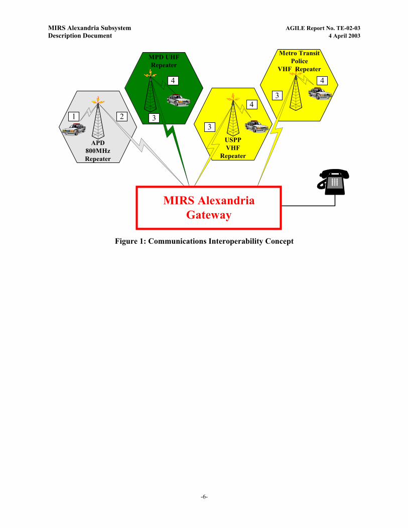
The MIRS approach to achieving interoperability is shown in Figure 1. The four hexagons at the top of the figure represent the radio systems of four of the participating agencies. Each system includes at least one repeater to provide coverage throughout that agency’s jurisdiction. The different colors of the hexagons signify the different frequency bands at which each radio system operates.
Consider a scenario in which a connection is established among channels of the APD, MPD, USPP, and Metro Transit radio systems. For example, transmissions from an APD officer (1) are received by the APD repeater and re-broadcast to all APD units. Transmissions are (2) received simultaneously at the MIRS gateway, and then rebroadcast on the input frequencies of the other participating agencies repeaters (3) that are interconnected through the gateway. The agencies’ repeater sites receive the transmission and in-turn, re-broadcast out to the individual radios of the respective agencies (4).
A connection can also include a telephone. Connections can be made between two or more systems, so that in addition to two-way connections between radios, the gateway can simultaneously connect all interfaces (radios and telephone) to provide a conference call capability that can be used during multi-jurisdictional incidents.
Connections are established through the system only when needed. Under normal circumstances, when interoperability is not required, agency radio systems work independently, as was done prior to installation of the system. The specific details of the circumstances and procedures, under which connections will be established and terminated, are defined under the MIRS amendment to PMARS.
-5-
MIRS Alexandria Subsystem AGILE Report No. TE-02-03 Description Document 4 April 2003
APD800MHzRepeater
USPPVHF
Repeater
MPD UHFRepeater
Metro TransitPolice
VHF Repeater
1 2 3
4
3
43
4
MIRS AlexandriaGateway
Figure 1: Communications Interoperability Concept
-6-

MIRS Alexandria Subsystem AGILE Report No. TE-02-03 Description Document 4 April 2003
3. PARTICIPATING AGENCY RADIO SYSTEMS As shown in Figure 1, communications interoperability is achieved by interfacing the
MIRS gateway with the land mobile radio systems of the participating agencies. The gateway subsystem must provide 100% coverage to the repeaters listed in Table 1. Specific operating frequencies were obtained directly from each participating agency.
Table 1: Radio System and Repeater Site Parameters
Agency Radio Type Freq Band APD Trunked 800 MHz, Motorola Astro Type II,
SmartNet 800
Metro PD Conventional UHF
US Park Police Conventional VHF
Metro Transit Police Conventional VHF
Maryland State Police (MD SP) Motorola LB CDM 1550 36-42Mhz Lo-Band VHF
Arlington PD (Arl PD) Trunked 800 MHz, Motorola Astro Type II, SmartNet
800
Prince Georges County PD (PGCO PD) Motorola MCS 2000 Type II UHF & UHFT Band
403-512 Mhz
UHF T-Band
Airport Trunked 800 MHz, Motorola Astro Type II, SmartNet
800
Fairfax County PD (FX Co.) Trunked 800 MHz, Motorola Astro Type II, SmartNet
800
US Capitol Police (US Capitol) Motorola Astro Spectra VHF Digital VHF
US Marshals Svc (USMS) Motorola Astro Spectra VHF Digital VHF
FBI Motorola Astro Spectra VHF Digital VHF
Virginia State Police (VA SP) Motorola Astro Spectra VHF Digital VHF
Federal Protective Svc. (FPS) Motorola Astro Digital UHF 403-433 Mhz UHF
Virginia Dept. of Transportation (VDOT) Motorola CDM 1550 LB 42-50MHz Low Band VHF
Maryland Dept. of Transportation (MDOT)
Motorola CDM 1550 LB 42-50MHz Low Band VHF
-7-
MIRS Alexandria Subsystem AGILE Report No. TE-02-03 Description Document 4 April 2003
4. ALEXANDRIA SUBSYSTEM The Alexandria subsystem is physically located at the Alexandria Police Department
headquarters building, 2003 Mill Road in Alexandria. The building complex consists of a multi-story brick building, with a lower roofline, 3 stories high, housing the MIRS system VHF/UHF & 800Mhz Antennas. Low-band MIRS antennas are installed on a penthouse that is located on the roof of the taller jailhouse section of the complex.
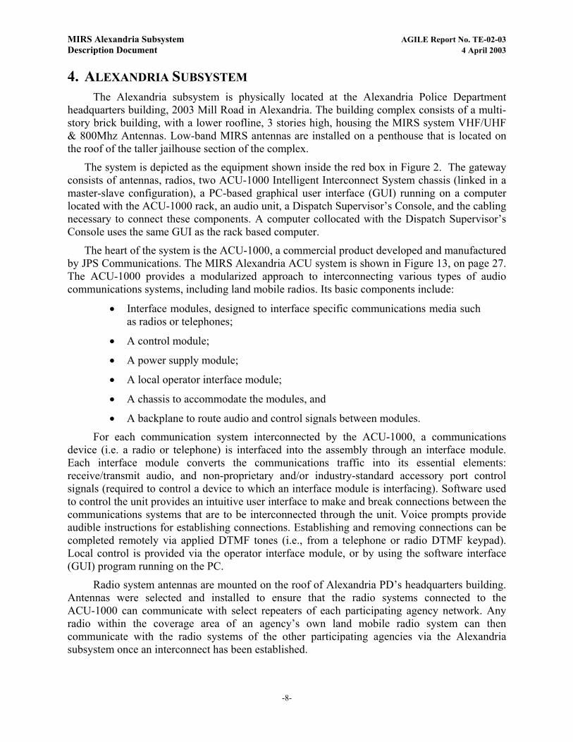
The system is depicted as the equipment shown inside the red box in Figure 2. The gateway consists of antennas, radios, two ACU-1000 Intelligent Interconnect System chassis (linked in a master-slave configuration), a PC-based graphical user interface (GUI) running on a computer located with the ACU-1000 rack, an audio unit, a Dispatch Supervisor’s Console, and the cabling necessary to connect these components. A computer collocated with the Dispatch Supervisor’s Console uses the same GUI as the rack based computer.
The heart of the system is the ACU-1000, a commercial product developed and manufactured by JPS Communications. The MIRS Alexandria ACU system is shown in Figure 13, on page 27. The ACU-1000 provides a modularized approach to interconnecting various types of audio communications systems, including land mobile radios. Its basic components include:
• Interface modules, designed to interface specific communications media such as radios or telephones;
• A control module;
• A power supply module;
• A local operator interface module;
• A chassis to accommodate the modules, and
• A backplane to route audio and control signals between modules.
For each communication system interconnected by the ACU-1000, a communications device (i.e. a radio or telephone) is interfaced into the assembly through an interface module. Each interface module converts the communications traffic into its essential elements: receive/transmit audio, and non-proprietary and/or industry-standard accessory port control signals (required to control a device to which an interface module is interfacing). Software used to control the unit provides an intuitive user interface to make and break connections between the communications systems that are to be interconnected through the unit. Voice prompts provide audible instructions for establishing connections. Establishing and removing connections can be completed remotely via applied DTMF tones (i.e., from a telephone or radio DTMF keypad). Local control is provided via the operator interface module, or by using the software interface (GUI) program running on the PC.
Radio system antennas are mounted on the roof of Alexandria PD’s headquarters building. Antennas were selected and installed to ensure that the radio systems connected to the ACU-1000 can communicate with select repeaters of each participating agency network. Any radio within the coverage area of an agency’s own land mobile radio system can then communicate with the radio systems of the other participating agencies via the Alexandria subsystem once an interconnect has been established.
-8-
MIRS Alexandria Subsystem AGILE Report No. TE-02-03 Description Document 4 April 2003
USPP
DSP1RadioInter-Face
DSP1RadioInter-Face
DSP1RadioInter-Face
DSP1RadioInter-Face
AdditionalAgencies800MHz
VHFLBVHFUHF800
MHz
PSTNPhoneInter-face
DSP1RadioInter-Face
DSP1RadioInter-Face
DSP1RadioInter-Face
DSP1RadioInter-Face
HSP2LocalInter-face
Dispatch Supervisor'sConsole
CPM2Con-
troller
ACU-1000
Radios
Equipment Racks inAPD Communications
Center
AntennasMounted onAPD Roof(s)
APD
MPD UHFRepeater
AdditionalAgencies
VHF Low Band
AdditionalAgencies
UHF
Metro TransitPolice
AdditionalAgencies
VHF
MIRS Alexandria Gateway
Figure 2: Alexandria Subsystem Architecture
-9-
MIRS Alexandria Subsystem AGILE Report No. TE-02-03 Description Document 4 April 2003
The ACU-1000 and radios is mounted in equipment racks that are located in the Equipment Room of the Dispatch Center located at Alexandria PD’s headquarters building. The radios are pre-programmed with frequencies licensed to the participating agencies. The radios are set to a default channel that a participating agency designates for inter-agency communications. Radio channels may be switched manually as required to transmit and receive on a different frequency channel, or to select an operating frequency for a different participating agency (within the individual radio and antenna limitations of each radio system).
Figure 3 provides a diagram of the MIRS Alexandria gateway. As shown, the gateway provides the ability to provide interconnects between 18 agency radio systems, an operator console in the communications center, and a Voice over IP circuit via the JPS NXU-2. Also, as part of this 18-radio configuration, two low-band radios were remotely installed in the Jail building (part of the public safety complex), and remote connections installed through the use of CPI CR211A & MCP200 equipment. The CPI CR211A remote heads are connected to the ACU-1000 in the equipment rack. As was the case with the original system, these radios are primarily tuned to channels for the agencies listed on Figure 3, but could be re-tuned to a number of pre-programmed channels within a given radios operating range.
The gateway includes the ability to control the ACU-1000 locally, from the Communications center, or through an IP connection via the NXU-2. The point of control must be selected by selecting the proper port on a 4-position serial port switch.
-10-

MIRS Alexandria Subsystem AGILE Report No. TE-02-03 Description Document 4 April 2003
PSTN-1
Am
plifi
edSp
eake
r
6
4
2
3
1
MIR
S A
lexa
ndria
Sub
syst
em M
ajor
Com
pone
nts
- Pos
t Ex
pans
ion
Inte
rfac
e Ca
bles
Inte
rfac
e Ca
bles
5
Rem
ote
LB r
adio
sat
Ale
xand
ria J
ail
7
8
Not
e: T
he c
ard
slot
ass
ignm
ent &
cab
ling
toth
e A
CU
-100
0 m
any
not m
atch
the
syst
emde
ploy
ed, a
nd is
for i
llust
ratio
n pu
rpos
es o
nly.
Mot
orol
a M
CS-
2000
Typ
e II
470-
512
Mhz
PGC
O P
DU
HF
Maxrad BMOY 4705UHF Yagi +9.2dBi
MaxradMYS4505UHF Yagi +9.2dBi
Mot
orol
a M
CS-
2000
Typ
e II
450-
470
Mhz
MPD
C UH
F
MaxradMYS4705UHF Yagi +9.2dBi
Mot
orol
a M
CS-
2000
Typ
e II
470-
512
Mhz
PGC
O P
DU
HF
Celwave RFS 10108-1800Mhz YAGI +10dBi
800
Mot
orol
a A
stro
Spe
ctra
Dig
ital
800
Mhz
Fx C
ount
yCushcraft S8063B
800Mhz Omni +3dBi
800
Mot
orol
a A
stro
Spe
ctra
Dig
ital
800
Mhz
APD
UH
F
Mot
orol
a A
stro
Spe
ctra
Dig
ital
403-
433
Mhz
Fede
ral P
rot.
Svc
Maxrad BMOY 4065UHF Yagi +9.2dBi
UH
FT
Mot
orol
a A
stro
Spe
ctra
Dig
ital
482-
512
Mhz
Tran
s PD
Maxrad BMOY 4405UHF Yagi +9.2dBi
UH
FT
Mot
orol
a A
stro
Spe
ctra
Dig
ital
482-
512
Mhz
Tran
s PD
Maxrad BMOY 4705UHF Yagi +9.2dBi
VHF
Mot
orol
a A
stro
Spe
ctra
Dig
ital
146-
174
Mhz
FBI
Sinclair SRL-206BVHF Yagi +9.5dBi
VHF
Mot
orol
a A
stro
Spe
ctra
Dig
ital
146-
174
Mhz
US
Cap
itol
Sinclair SRL-206BVHF Yagi +9.5dBi
PSM
-1H
SP-2
CPM-2
DSP-1
DSP-1
DSP-1
DSP-1
DSP-1
DSP-1
DSP-1
DSP-1
DSP-1
DSP-1
DSP-1
DSP-1
PSM
-1H
SP-2
CPM-2
DSP-1
DSP-1
DSP-1
DSP-1
DSP-1
DSP-1
DSP-1
DSP-1
DSP-1
PSTN-1
PSTN-1
9
Mot
orol
a M
CS-
2000
Typ
e II
Tran
s PD VH
F
Sinclair SRL-206BVHF Yagi +9.5dBi
Antennex YS1503VHF Yagi +7.1dBi
Ante
nna
Cha
nge
Antennex YS1503VHF Yagi +7.1dBi
Mot
orol
a M
CS-
2000
Typ
e II
USP
P VHF
Sinclair SRL-206BVHF Yagi +9.5dBi
Ante
nna
Cha
nge
10
11
12
CPI
MC
R21
1A R
emot
e fo
rM
otor
ola
CD
M 1
550
LB 4
2-50
Mhz
CPI
MC
R21
1A R
emot
e fo
rM
otor
ola
CD
M 1
550
LB 3
6-42
Mhz
VA &
MD
Hig
hway
Dep
t
MD
Sta
te P
olic
e
LB
Mot
orol
a C
DM
155
0 LB
42-5
0Mhz
VA &
MD
Hig
hway
Decibel ProductsDB201-L LB Omni
+2.1dBi
CPI
MC
P200
LB
Mot
orol
a C
DM
155
0 LB
36-4
2Mhz
MD
SP
SinclairSRL-101A Omni
+2.1dBi
CPI
MC
P200
IP N
etVi
perN
ET V
oIP
NXU
-2 V
oIP
DSL
Mod
em
DSL
Rou
ter
Com
man
d C
ente
r LE-
10
Rem
ote
Han
set
AC
U-1
000
#2A
CU
-100
0 #1
IP N
et
DSL
Mod
em
DSL
Rou
ter
Com
pute
r
GU
I
Com
pute
r
GU
I
ABC
D S
eria
lSw
itch
NXU
-2 V
oIP
Loca
l Con
trol
Com
Cen
ter
Rem
ote
Con
trol
via
IP N
ET
OPE
N
Loca
lH
ands
et
800
Mot
orol
a A
stro
Spe
ctra
Dig
ital
800
Mhz
Rea
gan
Nat
. Apt
. & IT
AC
Cushcraft S8063B800Mhz Omni +3dBi
800
Mot
orol
a A
stro
Spe
ctra
Dig
ital
800
Mhz
Arli
ngto
n PD
Celwave RFS 10108-1800Mhz YAGI +10dBi
USM
S VHF
Mot
orol
a A
stro
Spe
ctra
Dig
ital
146-
174
Mhz
Celwave BA1010-1Onmi +2.14dBi
VHF
Mot
orol
a A
stro
Spe
ctra
Dig
ital
146-
174
Mhz
Sinclair SRL-206BVHF Yagi +9.5dBi
VA S
P
13
14
15
18
16
17
12
34
56
78
910
1112
1314
1516
1718
1920
2122
2324
17
18
19
20
Figure 3: MIRS Alexandria Subsystem Architecture – Subsequent to Gateway Expansion
-11-
MIRS Alexandria Subsystem AGILE Report No. TE-02-03 Description Document 4 April 2003
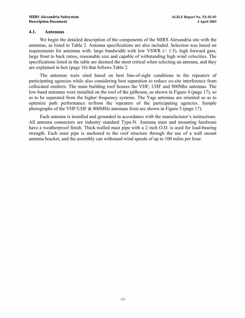
4.1. Antennas
We begin the detailed description of the components of the MIRS Alexandria site with the antennas, as listed in Table 2. Antenna specifications are also included. Selection was based on requirements for antennas with: large bandwidth with low VSWR (< 1.5), high forward gain, large front to back ratios, reasonable size and capable of withstanding high wind velocities. The specifications listed in the table are deemed the most critical when selecting an antenna, and they are explained in box (page 16) that follows Table 2.
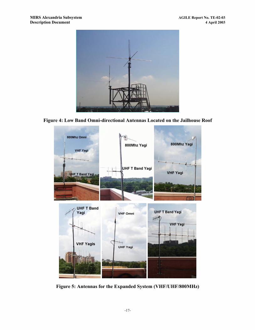
The antennas were sited based on best line-of-sight conditions to the repeaters of participating agencies while also considering best separation to reduce co-site interference from collocated emitters. The main building roof houses the VHF, UHF and 800Mhz antennas. The low-band antennas were installed on the roof of the jailhouse, as shown in Figure 4 (page 17), so as to be separated from the higher frequency systems. The Yagi antennas are oriented so as to optimize path performance to/from the repeaters of the participating agencies. Sample photographs of the VHF/UHF & 800MHz antennas from are shown in Figure 5 (page 17).
Each antenna is installed and grounded in accordance with the manufacturer’s instructions. All antenna connectors are industry standard Type-N. Antenna mast and mounting hardware have a weatherproof finish. Thick-walled mast pipe with a 2 inch O.D. is used for load-bearing strength. Each mast pipe is anchored to the roof structure through the use of a wall mount antenna bracket, and the assembly can withstand wind speeds of up to 100 miles per hour.
-12-
MIRS Alexandria Subsystem AGILE Report No. TE-02-03 Description Document 4 April 2003
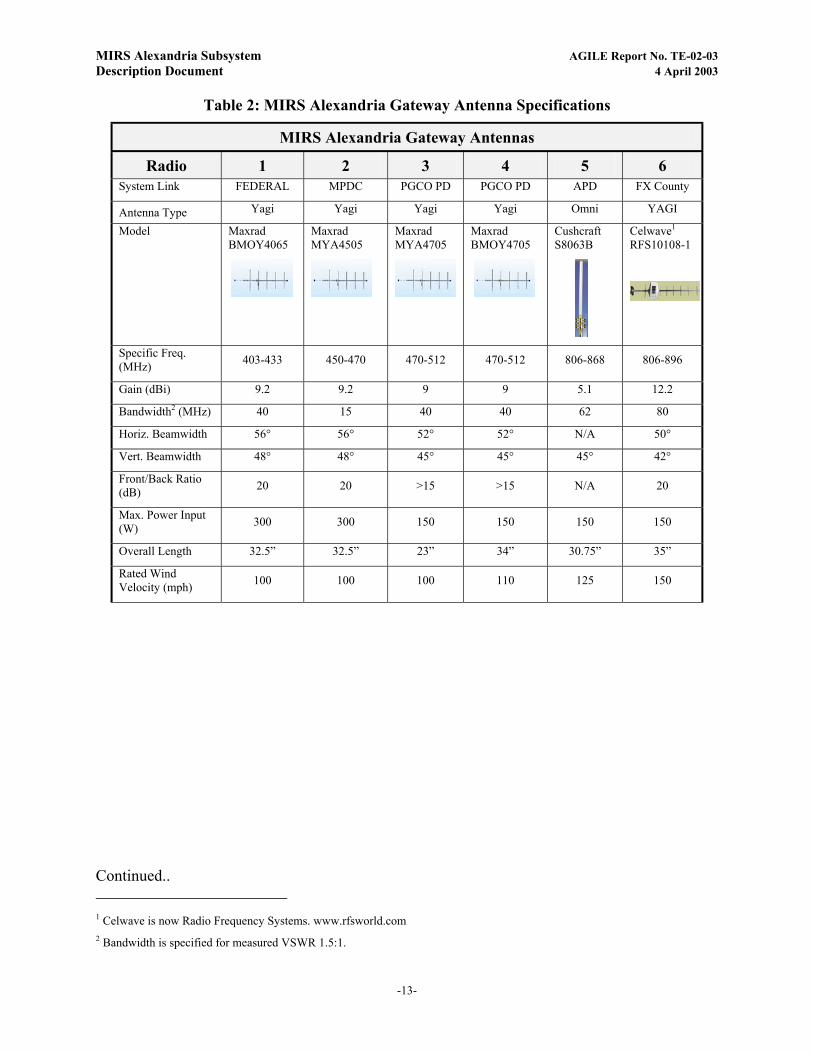
Table 2: MIRS Alexandria Gateway Antenna Specifications
MIRS Alexandria Gateway Antennas
Radio 1 2 3 4 5 6 System Link FEDERAL MPDC PGCO PD PGCO PD APD FX County
Antenna Type Yagi Yagi Yagi Yagi Omni YAGI
Model Maxrad BMOY4065
Maxrad MYA4505
Maxrad MYA4705
Maxrad BMOY4705
Cushcraft S8063B
Celwave1 RFS10108-1
Specific Freq. (MHz) 403-433 450-470 470-512 470-512 806-868 806-896
Gain (dBi) 9.2 9.2 9 9 5.1 12.2
Bandwidth2 (MHz) 40 15 40 40 62 80
Horiz. Beamwidth 56° 56° 52° 52° N/A 50°
Vert. Beamwidth 48° 48° 45° 45° 45° 42°
Front/Back Ratio (dB) 20 20 >15 >15 N/A 20
Max. Power Input (W) 300 300 150 150 150 150
Overall Length 32.5” 32.5” 23” 34” 30.75” 35”
Rated Wind Velocity (mph) 100 100 100 110 125 150
Continued.. 1 Celwave is now Radio Frequency Systems. www.rfsworld.com 2 Bandwidth is specified for measured VSWR 1.5:1.
-13-

MIRS Alexandria Subsystem AGILE Report No. TE-02-03 Description Document 4 April 2003
Table 3 (cont.): MIRS Alexandria Gateway Antenna Specifications
MIRS Alexandria Gateway Antennas (continued) Radio 7 8 9 10 11 12
System Link Reagan Nat Apt ARL. PD Trans PD USPP US Capitol FBI
Antenna Type OMNI Yagi Yagi Yagi Yagi Yagi
Model Cushcraft S8063B
Celwave3 RFS10108-1
Sinclair SRL206B
Sinclair SRL206B
Sinclair SRL206B
Sinclair SRL206B
Specific Freq. (MHz) 806-868 806-896 138-1744 138-1744 138-1744 138-1744
Gain (dBi) 5.1 12.2 11.6 11.6 11.6 11.6
Bandwidth2 (MHz) 62 80 6 6 6 6
Horiz. Beamwidth N/A 50° 56° 56° 56° 56°
Vert. Beamwidth 45° 42° 46° 46° 46° 46°
Front/Back Ratio (dB) 20 20 17 17 17 17
Max Power (W) 150 150 250 250 250 250
Overall Length 35” 35” 114” 114” 114” 114”
Rated Wind Velocity (mph) 150 150 130 130 130 130
Continued…
3 Celwave is now Radio Frequency Systems. www.rfsworld.com 4 Several models are available within this band, you must order the correct model
-14-
MIRS Alexandria Subsystem AGILE Report No. TE-02-03 Description Document 4 April 2003
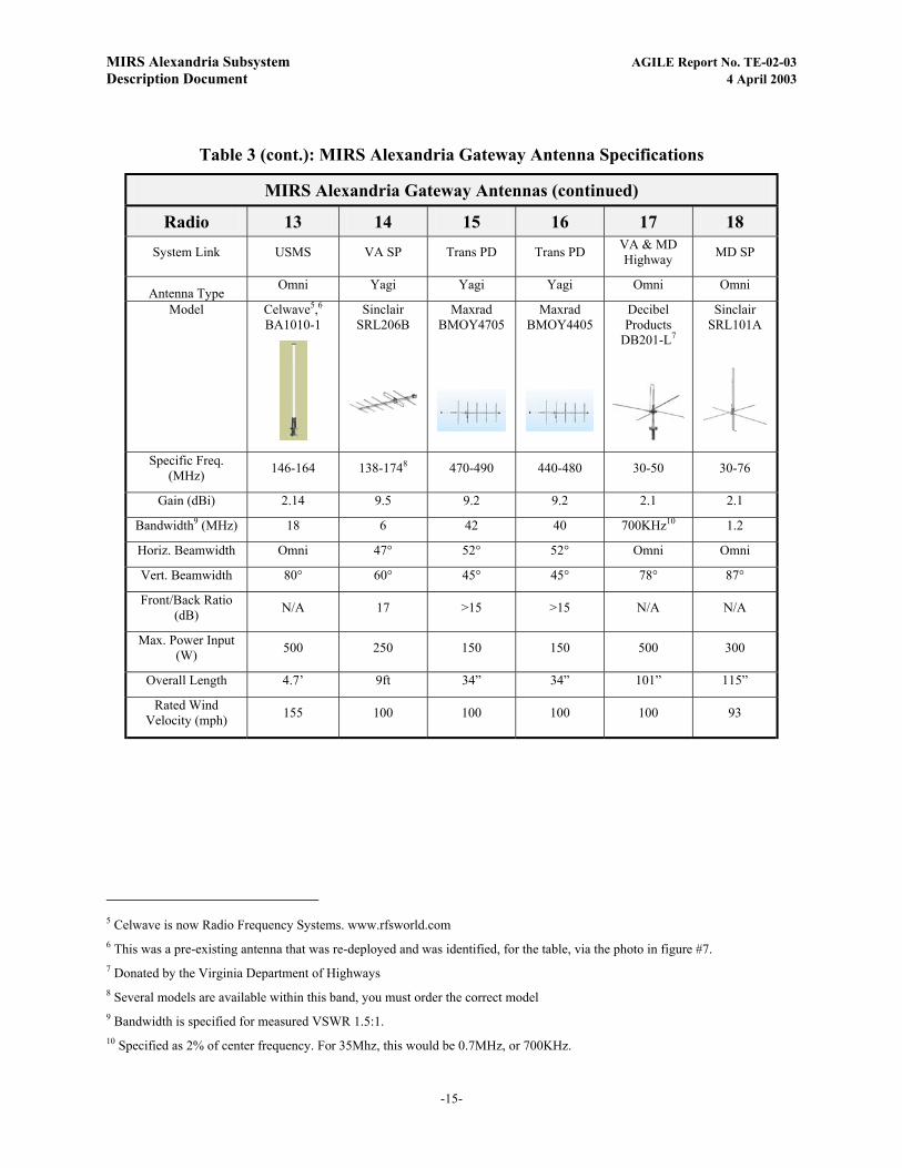
Table 3 (cont.): MIRS Alexandria Gateway Antenna Specifications
MIRS Alexandria Gateway Antennas (continued)
Radio 13 14 15 16 17 18 System Link USMS VA SP Trans PD Trans PD VA & MD
Highway MD SP
Antenna Type Omni Yagi Yagi Yagi Omni Omni
Model Celwave5,6 BA1010-1
Sinclair SRL206B
Maxrad BMOY4705
Maxrad BMOY4405
Decibel Products
DB201-L7
Sinclair SRL101A
Specific Freq. (MHz) 146-164 138-1748 470-490 440-480 30-50 30-76
Gain (dBi) 2.14 9.5 9.2 9.2 2.1 2.1
Bandwidth9 (MHz) 18 6 42 40 700KHz10 1.2
Horiz. Beamwidth Omni 47° 52° 52° Omni Omni
Vert. Beamwidth 80° 60° 45° 45° 78° 87°
Front/Back Ratio (dB) N/A 17 >15 >15 N/A N/A
Max. Power Input (W) 500 250 150 150 500 300
Overall Length 4.7’ 9ft 34” 34” 101” 115”
Rated Wind Velocity (mph) 155 100 100 100 100 93
5 Celwave is now Radio Frequency Systems. www.rfsworld.com 6 This was a pre-existing antenna that was re-deployed and was identified, for the table, via the photo in figure #7. 7 Donated by the Virginia Department of Highways 8 Several models are available within this band, you must order the correct model 9 Bandwidth is specified for measured VSWR 1.5:1. 10 Specified as 2% of center frequency. For 35Mhz, this would be 0.7MHz, or 700KHz.
-15-

MIRS Alexandria Subsystem AGILE Report No. TE-02-03 Description Document 4 April 2003
Antenna Parameter Background
The antenna gain specification represents the relative directivity of an antenna, or the ability of the antenna to focus the applied energy in a given direction, as compared to a reference antenna. Usually antenna gains are expressed in units of dBi, or dBd. The dB portion of this unit is a measure of the power ratio between the antenna and its reference, where the ratio of powers in dB is 10 log10 P2/P1. The ‘i’ of the unit is an identifier of the reference being used. In this case the ‘i’ stands for an isotropic reference. An isotropic reference is a theoretically ideal radiator that emits energy equally in all directions, essentially having a spherical radiation pattern. The other common reference is dBd, or gain referred to a theoretical half-wave dipole. A half-wave dipole usually has a 2.1dB gain over a theoretical isotropic radiator, so if comparing advertised antenna gain figures, 2.1dB must be added or subtracted to keep a constant dB gain reference. Given that the reference radiator (antenna) and the target antenna radiate the same amount of energy, the gain of the target antenna represents its ability to steer (focus) the applied radio frequency energy presented to the antenna in a desired direction.
The front to back ratio of an antenna references the ratio of energy being emitted in the forward pointing direction of the antenna as compared to that being emitted in the rearward direction. For our system, this specification applies to the installed yagi antennas. (This applies to both receive as well as transmit). Monopole and dipole antennas radiate energy in a donut shaped pattern and therefore do not have such a specification. This specification represents the degree of an antennas’ ability to direct the applied RF energy in a forward facing direction.
The next specification of the directivity of an antenna is the horizontal and vertical beam-width of an antenna’s radiation pattern. An antenna’s radiation pattern can be represented by an array of radiation lobes. It is very common for an antenna radiation pattern to consist of both main and side lobes, with the main lobes representing the majority of the antennas radiated energy. The horizontal and vertical beamwidth specifications provide an idea of the size of the main radiation lobe. The unit of measure for beamwidth is a unit of degrees, and represents the angular difference between the direction of the maximum radiated energy and the direction of half the maximum energy level.
Finally, Voltage Standing Wave Ratio, or VSWR, is a ratio of the voltage being supplied to an antenna feed line to the voltage being reflected back down the feed line to the source by the antenna. VSWR is typically measured at a transmitter end of a feed line. The equation for VSWR follows below.
VSWR = Vsupplied + Vreflected Vsupplied - Vrefelcted
A low VSWR rating over a specified frequency range usually identifies an antenna that is efficient at transferring power from the feed line to the atmosphere over the specified frequency range. A high VSWR as measured at a transmitter most likely indicates incorrect, mismatched, poorly tuned or defective antenna/feed line system components. A high VSWR will detract from system performance, and possibly damage transmitting equipment. VSWR should always be measured upon system installation and periodically during routine system maintenance.
Another useful specification used in conjunction with VSWR is antenna bandwidth. Bandwidth is a representation of antenna VSWR performance over a range of frequencies, but is most commonly used to identify the most ideal operating range of frequencies for an antenna. Whereas an antenna may be capable of transmitting over a range of 100 MHz, its ideal range or effective bandwidth, with a VSWR less than 2:1 (for example), may only be 10 MHz. When used in conjunction with gain, finding an antenna presenting a low VSWR rating over a desired bandwidth of operation is ideal. Such a specification identifies an antenna that can efficiently couple the applied energy (power) into the atmosphere over a desired frequency band, allowing frequency changes (perhaps to inter-operate with multiple agencies equipment) without re-tuning or changing antennas.
-16-
MIRS Alexandria Subsystem AGILE Report No. TE-02-03 Description Document 4 April 2003
Figure 4: Low Band Omni-directional Antennas Located on the Jailhouse Roof
Figure 5: Antennas for the Expanded System (VHF/UHF/800MHz)
-17-
MIRS Alexandria Subsystem AGILE Report No. TE-02-03 Description Document 4 April 2003
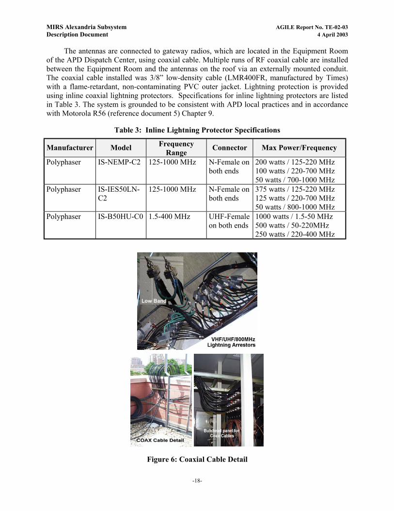
The antennas are connected to gateway radios, which are located in the Equipment Room of the APD Dispatch Center, using coaxial cable. Multiple runs of RF coaxial cable are installed between the Equipment Room and the antennas on the roof via an externally mounted conduit. The coaxial cable installed was 3/8” low-density cable (LMR400FR, manufactured by Times) with a flame-retardant, non-contaminating PVC outer jacket. Lightning protection is provided using inline coaxial lightning protectors. Specifications for inline lightning protectors are listed in Table 3. The system is grounded to be consistent with APD local practices and in accordance with Motorola R56 (reference document 5) Chapter 9.
Table 3: Inline Lightning Protector Specifications
Manufacturer Model Frequency Range Connector Max Power/Frequency
Polyphaser IS-NEMP-C2
125-1000 MHz N-Female on both ends
200 watts / 125-220 MHz 100 watts / 220-700 MHz 50 watts / 700-1000 MHz
Polyphaser IS-IES50LN-C2
125-1000 MHz N-Female on both ends
375 watts / 125-220 MHz 125 watts / 220-700 MHz 50 watts / 800-1000 MHz
Polyphaser IS-B50HU-C0 1.5-400 MHz UHF-Female on both ends
1000 watts / 1.5-50 MHz 500 watts / 50-220MHz 250 watts / 220-400 MHz
Figure 6: Coaxial Cable Detail
-18-

MIRS Alexandria Subsystem AGILE Report No. TE-02-03 Description Document 4 April 2003
4.2. Equipment Racks
The VHF/UHF, 800MHz radio equipment and ACU-1000 system are mounted in 19” racks (78” high) that were installed in the second floor Equipment Room of the Communications Center building. In addition, low-band radio equipment is installed in a cabinet remotely located in the jail facility. The Equipment Room has a raised floor and cooling system to accommodate other equipment (not related to this system) already in place.
A drawing of the rack layout is depicted in Figure 7. Figure 8 is a photograph of the system. The Low-band cabinet, located in the Jail complex is depicted in Figure 9. The Low-band radios are remotely controlled from the main equipment area by way of CPI MCR211A Remote control system as shown in Figure 10.
-19-

MIRS Alexandria Subsystem AGILE Report No. TE-02-03 Description Document 4 April 2003
MIRS Alexandria Gateway - Equipment Layout
Rack #3, rear -facing rack Behind Rack #1
DC Power Supply
DC Power Supply
DC Breaker Panel
Coaxial N Connector Bulkhead Connector Panel
Rack #1
Shelf
Shelf
Shelf
Shelf
PSM-1 HSP-2 CPM-2
DSP-1DSP-1DSP-1DSP-1DSP-1DSP-1DSP-1DSP-1DSP-1PSTN-1PSTN-1PSTN-1
PSM-1 HSP-2 CPM
-2DSP-1DSP-1DSP-1DSP-1DSP-1DSP-1DSP-1DSP-1DSP-1DSP-1DSP-1DSP-1
Shelf
Shelf
Shelf
Shelf
Shelf
UHFT
Federal Prot. ServiceMotorola ASTRO W5 UHF
UHFT
VHF VHF
VHF VHF
VHF VHF
800 800
800 800
UHFT UHFT
UHFUHF
Rack #2
Shelf
Shelf
Shelf
Unrelated APD equipment
CPU SHELF
Keyboard Shelf
Shelf
Monitor
NXU-2 VoIP
ABCDSwitch
Shelf
ACU-1000 #1
ACU-1000 #2
CPU
VA & MD Dept of TransportationCPI MC211A Remote forMotorola CDM1550 LB 42-50Mhz
Amplified Speaker
Unrelated APDEquipment
Unrelated ADPEquipment
DSL Router
Metro DC policeMotorola MCS 2000 UHF
Prince Georges County PDMotorola MCS 2000 UHFT
Prince Georges County FDMotorola MCS 2000 UHFT
Alexandria PDMotorola Astro W7 800Mhz
Fairfax Cty PDMotorola Astro W7 800Mhz
Reagan National AirportMotorola Astro W7 800Mhz
Arlington Co, Police DeptMotorola Astro W7 800Mhz
Metro Transit PDMotorola MCS 2000 VHF
US Park PoliceMotorola MCS 2000 VHF
US Capitol PoliceMotorola Astro W5 VHF
FBI/Secret ServiceMotorola Astro W5 VHF
US Marshal ServiceMotorola Astro W5 VHF
VA State policeMotorola Astro W5 VHF
Metro Transit PoliceMotorola Astro W5 UHFT
Metro Transit PolceMotorola Astro W5 UHFT
MD State PoliceCPI MCR211A Remote forMotorola CDM1550 LB 36-42Mhz
Unrelated ADP Equipment
DSL Modem
A=Local ComputerB=Com Center ComputerC=NXU-2 for IP remoteD=Unused
VoIP JPS NXU-2 ViperNET
Unrelated ADP Equipment
Unrelated ADP Equipment
1 2 3 4 5 6 7 8 9
1 2
3 4
5 6
7 8
9 10
11 12
13 14
15 16
17 18
ABCD Serial Switch for ACUControl
19
10 1112
131415161718192021222324
Figure 7: MIRS Alexandria Gateway Equipment Layout
-20-

MIRS Alexandria Subsystem AGILE Report No. TE-02-03 Description Document 4 April 2003
Figure 8: MIRS Alexandria Gateway Equipment Racks
-21-
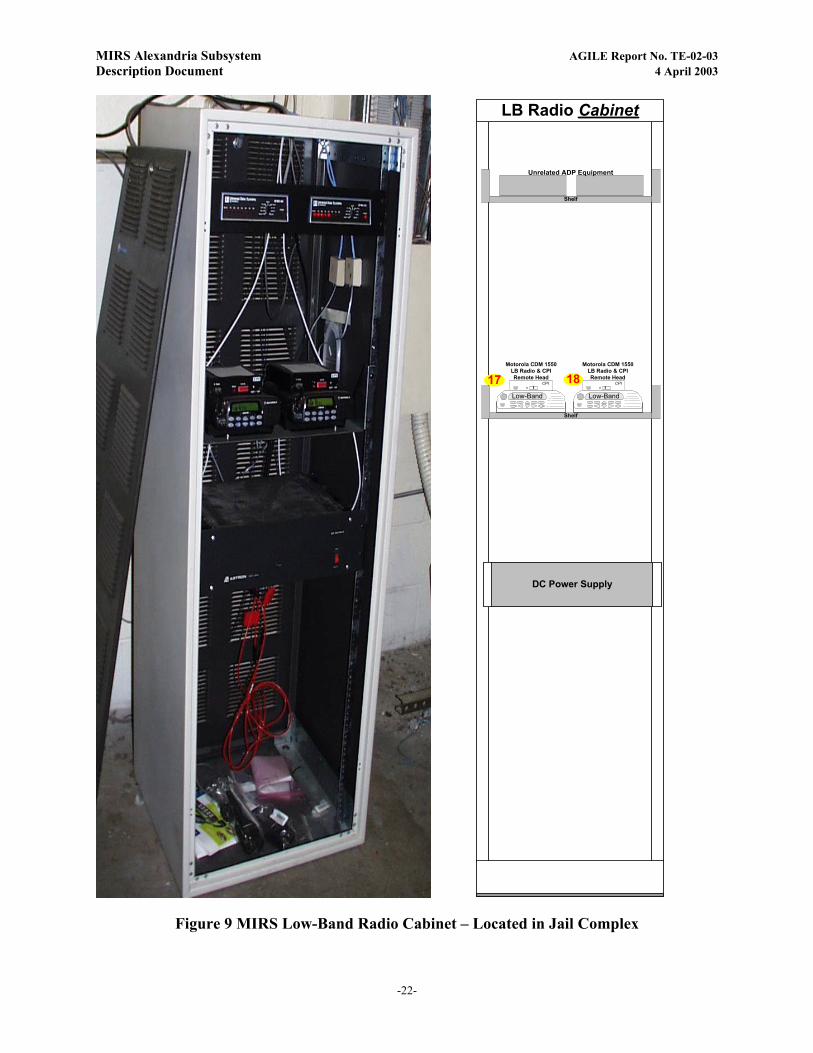
MIRS Alexandria Subsystem AGILE Report No. TE-02-03 Description Document 4 April 2003
LB Radio Cabinet
DC Power Supply
Shelf
Unrelated ADP Equipment
Shelf
Low-Band Low-Band��CPI � CPI
Motorola CDM 1550LB Radio & CPIRemote Head
Motorola CDM 1550LB Radio & CPIRemote Head
17 18
Figure 9 MIRS Low-Band Radio Cabinet – Located in Jail Complex
-22-
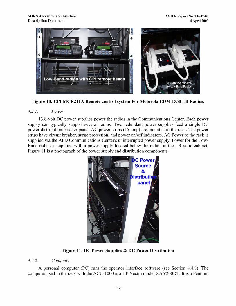
MIRS Alexandria Subsystem AGILE Report No. TE-02-03 Description Document 4 April 2003
Figure 10: CPI MCR211A Remote control system For Motorola CDM 1550 LB Radios.
4.2.1. Power
13.8-volt DC power supplies power the radios in the Communications Center. Each power supply can typically support several radios. Two redundant power supplies feed a single DC power distribution/breaker panel. AC power strips (15 amp) are mounted in the rack. The power strips have circuit breaker, surge protection, and power on/off indicators. AC Power to the rack is supplied via the APD Communications Center's uninterrupted power supply. Power for the Low-Band radios is supplied with a power supply located below the radios in the LB radio cabinet. Figure 11 is a photograph of the power supply and distribution components.
Figure 11: DC Power Supplies & DC Power Distribution
4.2.2. Computer
A personal computer (PC) runs the operator interface software (see Section 4.4.8). The computer used in the rack with the ACU-1000 is a HP Vectra model XA6/200DT. It is a Pentium
-23-
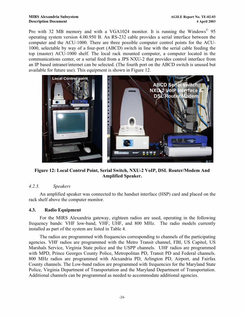
MIRS Alexandria Subsystem AGILE Report No. TE-02-03 Description Document 4 April 2003
Pro with 32 MB memory and with a VGA1024 monitor. It is running the Windows© 95 operating system version 4.00.950 B. An RS-232 cable provides a serial interface between the computer and the ACU-1000. There are three possible computer control points for the ACU-1000, selectable by way of a four-port (ABCD) switch in line with the serial cable feeding the top (master) ACU-1000 shelf. The local rack mounted computer, a computer located in the communications center, or a serial feed from a JPS NXU-2 that provides control interface from an IP based intranet/internet can be selected. (The fourth port on the ABCD switch is unused but available for future use). This equipment is shown in Figure 12.
Figure 12: Local Control Point, Serial Switch, NXU-2 VoIP, DSL Router/Modem And Amplified Speaker.
4.2.3. Speakers
An amplified speaker was connected to the handset interface (HSP) card and placed on the rack shelf above the computer monitor.
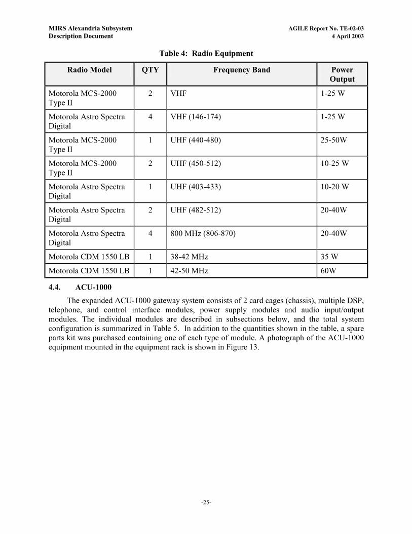
4.3. Radio Equipment For the MIRS Alexandria gateway, eighteen radios are used, operating in the following
frequency bands: VHF low-band, VHF, UHF, and 800 MHz. The radio models currently installed as part of the system are listed in Table 4.
The radios are programmed with frequencies corresponding to channels of the participating agencies. VHF radios are programmed with the Metro Transit channel, FBI, US Capitol, US Marshals Service, Virginia State police and the USPP channels. UHF radios are programmed with MPD, Prince Georges County Police, Metropolitan PD, Transit PD and Federal channels. 800 MHz radios are programmed with Alexandria PD, Arlington PD, Airport, and Fairfax County channels. The Low-band radios are programmed with frequencies for the Maryland State Police, Virginia Department of Transportation and the Maryland Department of Transportation. Additional channels can be programmed as needed to accommodate additional agencies.
-24-
MIRS Alexandria Subsystem AGILE Report No. TE-02-03 Description Document 4 April 2003
Table 4: Radio Equipment
Radio Model QTY Frequency Band Power Output
Motorola MCS-2000 Type II
2 VHF 1-25 W
Motorola Astro Spectra Digital
4 VHF (146-174) 1-25 W
Motorola MCS-2000 Type II
1 UHF (440-480) 25-50W
Motorola MCS-2000 Type II
2 UHF (450-512) 10-25 W
Motorola Astro Spectra Digital
1 UHF (403-433) 10-20 W
Motorola Astro Spectra Digital
2 UHF (482-512) 20-40W
Motorola Astro Spectra Digital
4 800 MHz (806-870) 20-40W
Motorola CDM 1550 LB 1 38-42 MHz 35 W
Motorola CDM 1550 LB 1 42-50 MHz 60W
4.4. ACU-1000 The expanded ACU-1000 gateway system consists of 2 card cages (chassis), multiple DSP,
telephone, and control interface modules, power supply modules and audio input/output modules. The individual modules are described in subsections below, and the total system configuration is summarized in Table 5. In addition to the quantities shown in the table, a spare parts kit was purchased containing one of each type of module. A photograph of the ACU-1000 equipment mounted in the equipment rack is shown in Figure 13.
-25-

MIRS Alexandria Subsystem AGILE Report No. TE-02-03 Description Document 4 April 2003
Table 5: ACU-1000 Hardware Configuration
Module Description Quantity Hardware Revision Software Revision
Chassis ACU-1000 Chassis #1 from the original system
1 -- N/A
PSM-1 60W Power Supply Module 1 A N/A
HSP-2 Handset and Speaker Module 1 C U34 1069-123 105 U4 1069-180 100 U5 1096-1981 400
CPM-2 Control Processor Module (System “Brain”)
1 E U4 1096-124 117 U5 V62C5181025L
PSTN-1 Interface to Telephone Network 1 C U8 S/W 1096-201 211
DSP-1 Digital Signal Processor (Radio Interface)
8 E U8 S/W 1096-201 203
Chassis ACU-1000 Chassis #2 1 -- N/A
PSM-1 60W Power Supply Module 1 A N/A
CPM-2 Control Processor Module 1 E U4 1096-124 117 U5 V62C5181025L
PSTN-1 Interface to Telephone Network 2 C U8 S/W 1096-201 211
DSP-1 Digital Signal Processor (Radio Interface)
10 E U8 S/W 1096-201 203
-26-

MIRS Alexandria Subsystem AGILE Report No. TE-02-03 Description Document 4 April 2003
Figure 13: MIRS Alexandria Gateway ACU-1000 Shelves
4.4.1. Chassis and Backplane
Each ACU-1000 chassis is a 19” wide, [EIA standard] rack-mounted 3 rack unit cage (5.25” tall, 11” deep) equipped with a backplane circuit board into which the system modules are inserted. An AC input module and power transformer assembly is located on a metal panel that is mounted to each ACU-1000 shelf backplane. The AC module is a combination AC line filter, power cable connector, input voltage selector, and fuse holder. The backplane provides internal 60-pin card edge connectors for the plug-in modules and D-subminiature connectors on the rear for external interfaces. An ACU-1000 backplane contains a 16-line audio bus, 8-bit digital bus, and a serial control bus.
4.4.2. PSM-1 Power Supply Module
A 60W DC power supply plugs into a dedicated slot at the left side of each chassis. It provides +15V unregulated, and +12V, -12V regulated DC. In addition to these voltages, each individual module generates +5V regulated DC from the +15V supply provided by the PSM-1.
4.4.3. CPM-2 Control Processor Module
A CPM-2 controller housed in each chassis provides control for all the other modules housed in each ACU-1000 chassis. The CPM-2 constantly polls all modules to track their current status via the internal eight-bit data bus. The CPM-2 module arbitrates the audio signals on the backplane, controls tone and voice prompting, and maintains password security. The CPM-2 keeps all system and module configuration parameters in flash memory. An RS-232 serial port supports remote control, programming, and monitoring of all the functions of the ACU-1000 system via an external computer or serial-interfaced console.
-27-

MIRS Alexandria Subsystem AGILE Report No. TE-02-03 Description Document 4 April 2003
4.4.4. HSP-2 Handset/Speaker/Prompt Module
The HSP-2 module provides a means to locally monitor, control, and configure the ACU-1000 system. A local operator can monitor audio via an internal speaker, plug in external headphones, and use the operator handset included with the HSP-2. The handset includes a Push-To-Talk (PTT) switch that must be closed for the operator’s voice to be transmitted. Control is via 3x4 DTMF keypad (standard telephone layout) that enables the operator to select a module and enter control/configuration data. By interfacing to the PSTN-1 module, the operator may place telephone calls manually using the HSP-2 keypad and handset.
4.4.5. PSTN-1 Telephone Interface Module
The PSTN-1 connects the ACU-1000 to a telephone network. This capability allows users to dial a telephone number from a radio (equipped with a DTMF keypad) or other device connected to the ACU-1000. It contains ring detect and Caller ID for automated system operation. It also provides Voice Operated Xmit (VOX) with configurable sensitivity, hang time, and a DTMF receiver/generator for control and call progress recognition. The front panel of the module provides two RJ-11C jacks for two telephones, although only one local telephone may be in use at a time.
4.4.6. DSP-1 Digital Signal Processor Module
The DSP-1 module is a radio interface module. The ACU-1000 uses one DSP-1 module per radio. All received audio is digitized through an analog to digital converter, and processed by the on-board DSP. This module sends and receives audio over 4-wire connections to/from the radio. It performs digital audio processing such as digital equalization, filtering, noise reduction, VOX, audio delay, and other features. The audio processing is determined by the programmable configuration settings. Received audio that is processed by the DSP-1 is then routed via the backplane to the other appropriate interface modules that have been designated by the user to be interconnected. The DSP-1 is also used to interface other non-radio devices.
4.4.7. System Software This high level software resides on the CPM-2 and controls all aspects of the
ACU-1000’s operation. It contains the interface protocol necessary for external computer control and determines various aspects of the operator’s control interface, including the timing of system voice prompts.
4.4.8. Console Software/Graphical User Interface
The Windows-based GUI software11 is operating under Windows© 95 on the PC residing in the equipment rack (see Section 4.2.2). As of the date that this paper was written, software version 2.08 had been implemented. The computer is connected to the CPM-2 module RS-232 serial port (via DB-9 RS-232 Serial Cable). It provides a convenient user interface for configuring and controlling the ACU-1000. Example screen shots of the user interface are shown in Figure 14. In these examples, the first shot depicts the fully expanded system. The second shot depicts the prompt for establishing (dialing) a PSTN circuit. The third shot depicts three,
11 Version Beta 4, Revision 10.
-28-

MIRS Alexandria Subsystem AGILE Report No. TE-02-03 Description Document 4 April 2003
simultaneous, independent nets. The Fourth shot depicts the detailed interface for configuring DSP-1 card parameters. A complete discussion of the user interface and commands can be found in the ACU-1000 Installation and Operation Manual (reference document 1).
Figure 14: ACU-1000 Operator User Interface Sample Screen Shots
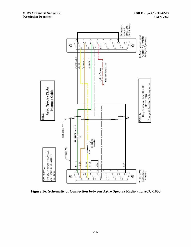
4.5. Radio/ACU-1000 Interface cables Radio specific cables were fabricated to connect the radios to the ACU-1000 interface
modules, and fabrication was based on the schematics shown in Figure 15, Figure 16, and Figure 17.
-29-

MIRS Alexandria Subsystem AGILE Report No. TE-02-03 Description Document 4 April 2003
Figure 15: Schematic Of Connection Between MCS-20000 Radio With ACU-1000
-30-
MIRS Alexandria Subsystem AGILE Report No. TE-02-03 Description Document 4 April 2003
Figure 16: Schematic of Connection between Astro Spectra Radio and ACU-1000
-31-

MIRS Alexandria Subsystem AGILE Report No. TE-02-03 Description Document 4 April 2003
1
8
9
15
1) Gnd2) N/A3) N/A4) N/A5) Gnd6) TX Out B (To Gnd for unbalanced audio)7) Aud Gnd8) RX In A9) N/A10) N/A11) N/A12) PTT (low)13) COR (low)14) TX Out A15) RX In B (To Gnd for unbalanced audio)
1) Gnd2) Earpiece (RX Out)3) PTT (Gnd to pin 2)4) Mic Audio (TX In)
RX Audio
TX Audio
Gnd
PTT
Shield Drain ground @ ACU-1000
.01uF
.01uF
MCR 211A Interconnect cable for ACU-1000 DSP-1 cardL3 CommunicationsBeta 1.0 cable as-built 08/26/2002 Phil Harris
DSP-1Male DB-15rear view
14
RJ-11*
1
4
1
44PDT
Switch
(Base)
(Handset)
* If a common coiled handset cord is used in costruction, the color code will depend on what end of thecord the is removed. Common headset cord construction is shown below. Ensure that the correct cord endis discarded so that when the handset is selected via the switch the circuit appears as a single, standardcord. Some cords have differing color codes, so adjust as needed.
MCR 211A
A/BSwitch
Box
To Low Band Radios
AlmondCoiledCord
BlackCoiledCord
NOTE: ACU-1000 DSP-1jumper JP1 must be setto select high impedance
4
1
1
4Typical coiled handsetcord schematic
RJ-11RJ-11Plug to
MCR 211Alocal Handset
Plug toMCR 211A
Base
Plug toMCR 211A*
Plug toMCR 211A
localHandset*
AlmondSheath
BlackSheath
Plug toMCR 211A*
ABC
A B C
BK
Y(W)GNRD
BK
Y(W)GNRD
41
1
4
1
41
4BK
Y(W)
GN
RD
Figure 17: Schematic of Cable between CPI MCR211A remote and a ACU-1000 DSP-1 card
4.6. Dispatcher’s Console The Gateway Subsystem design provides an interface at the dispatcher’s console within the
Dispatch Center.
The ACU-1000 assembly has two external audio connections, a standard 2-wire phone line, and a standard 4-wire analog audio line. These lines connect the ACU-1000 rack to a standalone audio console (Figure 18) in the Dispatch Center. The phone line is a standard 2-wire analog public switched telephone network (PSTN) line, and supports tone dialing. The audio console provides speaker, headset, and handset capability, plus a switch to control the phone line connection to/from the ACU-1000.
Figure 18: Remote Audio Console
-32-

MIRS Alexandria Subsystem AGILE Report No. TE-02-03 Description Document 4 April 2003
The graphical user interface (GUI) displayed on the PC at the equipment rack can also be displayed on a PC at the dispatcher’s console location. The computer is connected via an RS-232 line to the ACU-1000 in the Equipment Room and selected via the ABCD serial switch as discussed earlier in this report. One control point can be selected at a time. The minimum requirements for the computer are: a Pentium or equivalent processor with at least one 3½” floppy disk, one CD ROM drive and one unused DB-9 serial port for the RS-232 connection to the ACU-1000. According to JPS, the latest version of the operating system (3.12) will work with Windows© 95/98/NT and Windows© 2000. This version has not been tested with Windows© XP.
-33-

MIRS Alexandria Subsystem AGILE Report No. TE-02-03 Description Document 4 April 2003
5. INSTALLATION TASKS Integration of the gateway subsystem as described in the preceding section was
accomplished in a sequence of tasks. In this section, the following four tasks are summarized in the subsections that follow:
• Site survey;
• Procurement of parts and equipment;
• Site preparation (installation of antennas, equipment rack, and associated cabling); and
• Equipment Installation.
5.1. Site Survey The NLECTC-NE and APD team performed a site survey at APD to identify design
requirements for system installation. Floor plans were reviewed to determine placement of the equipment, availability of rack space, cooling, power, telephone line availability, and proximity to the dispatch center. Topographical maps were reviewed to identify terrain conditions and azimuth direction for line of site from the antennas at APD to the repeater sites of the participating agencies. The APD roof was surveyed to identify existing antennas, cable ports and measured for proper placement of the new antennas. There were also discussions regarding applicable regulations and codes (e.g., local building codes require flame-retardant cabling and lightning protection, FCC regulations restrict power levels).
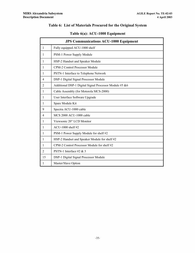
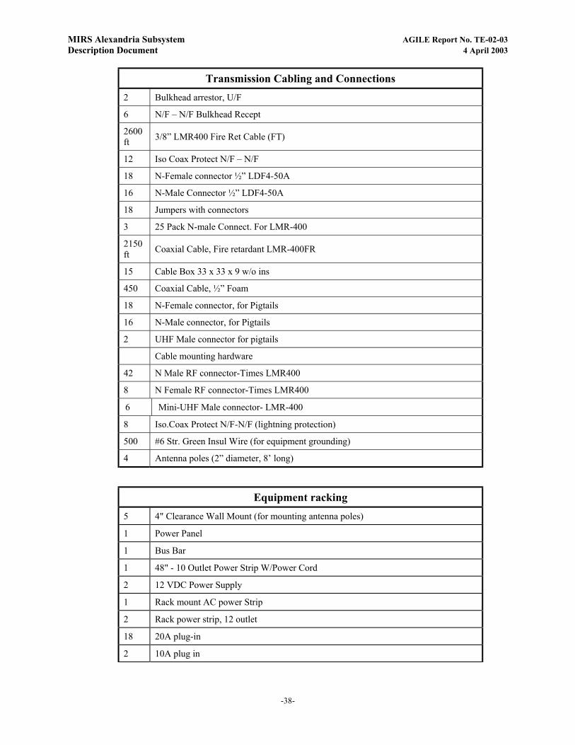
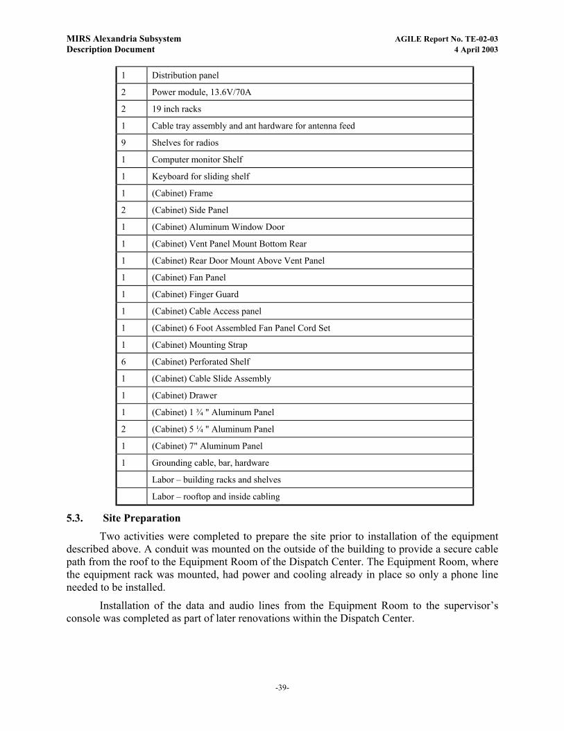
5.2. Procurement of Parts and Equipment Once the site survey was completed, the necessary equipment was procured based on the
discussion in Section 4. Table 6 provides a complete list of items procured. Total cost of procurement, including parts and specific contract installation items listed at the bottom of the table (but not including the site engineering provided by the AGILE team was (approximately) $123,000.
-34-
MIRS Alexandria Subsystem AGILE Report No. TE-02-03 Description Document 4 April 2003
Table 6: List of Materials Procured for the Original System
Table 6(a): ACU-1000 Equipment
JPS Communications ACU-1000 Equipment 1 Fully equipped ACU-1000 shelf
1 PSM-1 Power Supply Module
1 HSP-2 Handset and Speaker Module
1 CPM-2 Control Processor Module
1 PSTN-1 Interface to Telephone Network
4 DSP-1 Digital Signal Processor Module
2 Additional DSP-1 Digital Signal Processor Module #5 &6
1 Cable Assembly (for Motorola MCS-2000)
1 User Interface Software Upgrade
1 Spare Module Kit
9 Spectra ACU-1000 cable
4 MCS 2000 ACU-1000 cable
1 Viewsonic 20” LCD Monitor
1 ACU-1000 shelf #2
1 PSM-1 Power Supply Module for shelf #2
1 HSP-2 Handset and Speaker Module for shelf #2
1 CPM-2 Control Processor Module for shelf #2
2 PSTN-1 Interface #2 & 3
15 DSP-1 Digital Signal Processor Module
1 Master/Slave Option
-35-
MIRS Alexandria Subsystem AGILE Report No. TE-02-03 Description Document 4 April 2003
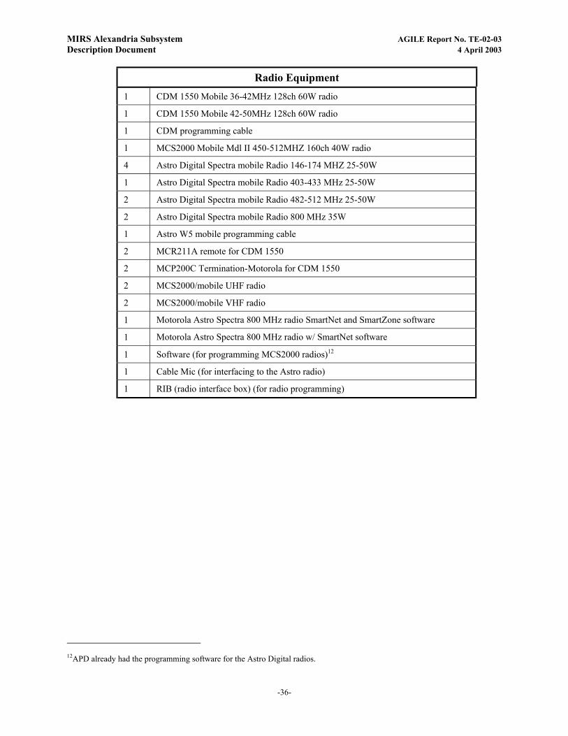
Radio Equipment
1 CDM 1550 Mobile 36-42MHz 128ch 60W radio
1 CDM 1550 Mobile 42-50MHz 128ch 60W radio
1 CDM programming cable
1 MCS2000 Mobile Mdl II 450-512MHZ 160ch 40W radio
4 Astro Digital Spectra mobile Radio 146-174 MHZ 25-50W
1 Astro Digital Spectra mobile Radio 403-433 MHz 25-50W
2 Astro Digital Spectra mobile Radio 482-512 MHz 25-50W
2 Astro Digital Spectra mobile Radio 800 MHz 35W
1 Astro W5 mobile programming cable
2 MCR211A remote for CDM 1550
2 MCP200C Termination-Motorola for CDM 1550
2 MCS2000/mobile UHF radio
2 MCS2000/mobile VHF radio
1 Motorola Astro Spectra 800 MHz radio SmartNet and SmartZone software
1 Motorola Astro Spectra 800 MHz radio w/ SmartNet software
1 Software (for programming MCS2000 radios)12
1 Cable Mic (for interfacing to the Astro radio)
1 RIB (radio interface box) (for radio programming)
12APD already had the programming software for the Astro Digital radios.
-36-

MIRS Alexandria Subsystem AGILE Report No. TE-02-03 Description Document 4 April 2003
Dispatch Supervisor’s Console 1 Serial Cable
1 Local Control- Mon, DTMF
1 Wall Plug for LE Remotes
200 Ft, 8 Cond. Cable-Shield
Antennas 2 152-159.9 9.5dB Single Yagi
1 806-896 10dB Single Yagi
1 806-866 3dB Fiberglass
1 450-470 9.2dB Gold Yagi
1 490-512 7.1dB Yagi
3 162-169.9 9.5dB Single Yagi
1 30-50 FT Omni
1 806-896 10dB Single Yagi
1 806-866 3dB Fiberglass
1 440-480 9 dBd Yagi
1 406-440 9 dBd Yagi
1 470-512 9 dBd Yagi
2 470-512 9 dB Yagi
2 Non-Penetrating Tripod
-37-
MIRS Alexandria Subsystem AGILE Report No. TE-02-03 Description Document 4 April 2003
Transmission Cabling and Connections 2 Bulkhead arrestor, U/F
6 N/F – N/F Bulkhead Recept
2600 ft 3/8” LMR400 Fire Ret Cable (FT)
12 Iso Coax Protect N/F – N/F
18 N-Female connector ½” LDF4-50A
16 N-Male Connector ½” LDF4-50A
18 Jumpers with connectors
3 25 Pack N-male Connect. For LMR-400
2150 ft Coaxial Cable, Fire retardant LMR-400FR
15 Cable Box 33 x 33 x 9 w/o ins
450 Coaxial Cable, ½” Foam
18 N-Female connector, for Pigtails
16 N-Male connector, for Pigtails
2 UHF Male connector for pigtails
Cable mounting hardware
42 N Male RF connector-Times LMR400
8 N Female RF connector-Times LMR400
6 Mini-UHF Male connector- LMR-400
8 Iso.Coax Protect N/F-N/F (lightning protection)
500 #6 Str. Green Insul Wire (for equipment grounding)
4 Antenna poles (2” diameter, 8’ long)
Equipment racking 5 4" Clearance Wall Mount (for mounting antenna poles)
1 Power Panel
1 Bus Bar
1 48" - 10 Outlet Power Strip W/Power Cord
2 12 VDC Power Supply
1 Rack mount AC power Strip
2 Rack power strip, 12 outlet
18 20A plug-in
2 10A plug in
-38-
MIRS Alexandria Subsystem AGILE Report No. TE-02-03 Description Document 4 April 2003
1 Distribution panel
2 Power module, 13.6V/70A
2 19 inch racks
1 Cable tray assembly and ant hardware for antenna feed
9 Shelves for radios
1 Computer monitor Shelf
1 Keyboard for sliding shelf
1 (Cabinet) Frame
2 (Cabinet) Side Panel
1 (Cabinet) Aluminum Window Door
1 (Cabinet) Vent Panel Mount Bottom Rear
1 (Cabinet) Rear Door Mount Above Vent Panel
1 (Cabinet) Fan Panel
1 (Cabinet) Finger Guard
1 (Cabinet) Cable Access panel
1 (Cabinet) 6 Foot Assembled Fan Panel Cord Set
1 (Cabinet) Mounting Strap
6 (Cabinet) Perforated Shelf
1 (Cabinet) Cable Slide Assembly
1 (Cabinet) Drawer
1 (Cabinet) 1 ¾ " Aluminum Panel
2 (Cabinet) 5 ¼ " Aluminum Panel
1 (Cabinet) 7" Aluminum Panel
1 Grounding cable, bar, hardware
Labor – building racks and shelves
Labor – rooftop and inside cabling
5.3. Site Preparation Two activities were completed to prepare the site prior to installation of the equipment
described above. A conduit was mounted on the outside of the building to provide a secure cable path from the roof to the Equipment Room of the Dispatch Center. The Equipment Room, where the equipment rack was mounted, had power and cooling already in place so only a phone line needed to be installed.
Installation of the data and audio lines from the Equipment Room to the supervisor’s console was completed as part of later renovations within the Dispatch Center.
-39-

MIRS Alexandria Subsystem AGILE Report No. TE-02-03 Description Document 4 April 2003
5.4. Equipment Installation
The first installation task was to mount the antennas on the parapet of the APD roof (see Section 4.1). Next the cabling was installed between the antenna locations and the Equipment Room. The 19” equipment racks were then installed in the Equipment Room.
The following items were installed into the equipment rack: the ACU-1000 system, radios, DC power supplies, the computer, fans, speakers, and associated interconnect cabling. The cables used to interconnect the radios and the ACU-1000 interface cards were fabricated as described in Section 4.5
The ACU-1000 GUI software was loaded onto the computer, and the radio transceivers were programmed to the frequency assignments described in Section4.3.
The dispatcher’s dispatch console (Section 4.6) in the dispatch room was then installed. This console has small footprint and provides direct access, control, and monitoring of the audio from the ACU-1000 system. GUI software driven user interface was installed on a desktop PC in the Dispatch Center to provide a convenient means of configuring the ACU-1000. An RS-232 interconnect was installed between the remote PC and the ACU-1000, with an A/B serial switch selecting the local rack mounted computer, or the dispatch desk computer.
-40-
MIRS Alexandria Subsystem AGILE Report No. TE-02-03 Description Document 4 April 2003
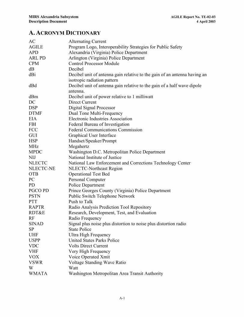
A. ACRONYM DICTIONARY AC Alternating Current AGILE Program Logo, Interoperability Strategies for Public Safety APD Alexandria (Virginia) Police Department ARL PD Arlington (Virginia) Police Department CPM Control Processor Module dB Decibel dBi Decibel unit of antenna gain relative to the gain of an antenna having an
isotropic radiation pattern dBd Decibel unit of antenna gain relative to the gain of a half wave dipole
antenna. dBm Decibel unit of power relative to 1 milliwatt DC Direct Current DSP Digital Signal Processor DTMF Dual Tone Multi-Frequency EIA Electronic Industries Association FBI Federal Bureau of Investigation FCC Federal Communications Commission GUI Graphical User Interface HSP Handset/Speaker/Prompt MHz Megahertz MPDC Washington D.C. Metropolitan Police Department NIJ National Institute of Justice NLECTC National Law Enforcement and Corrections Technology Center NLECTC-NE NLECTC-Northeast Region OTB Operational Test Bed PC Personal Computer PD Police Department PGCO PD Prince Georges County (Virginia) Police Department PSTN Public Switch Telephone Network PTT Push to Talk RAPTR Radio Analysis Prediction Tool Repository RDT&E Research, Development, Test, and Evaluation RF Radio Frequency SINAD Signal plus noise plus distortion to noise plus distortion radio SP State Police UHF Ultra High Frequency USPP United States Parks Police VDC Volts Direct Current VHF Very High Frequency VOX Voice Operated Xmit VSWR Voltage Standing Wave Ratio W Watt WMATA Washington Metropolitan Area Transit Authority
A-1