
Metrological traceability for AC High-Voltage in Inmetro...
4
8 th Brazilian Congress on Metrology, Bento Gonçalves/RS, 2015 1 Metrological traceability for AC High-Voltage in Inmetro up to 40 kV Patrícia C. de Oliveira Vitorio; Vladimir R. de Lima; Orsino Borges Filho; Leonardo A. Abreu de Souza and Otto W. Ganvini Asencios. National Institute of Metrology, Quality and Technology - Inmetro E-mail: [email protected] Abstract: This paper refers to a project carried out in Inmetro aiming to provide internal metrological traceability for 60 Hz AC High-Voltage up to 40 kV. It presents details about the method used, its equations and obtained results. A capacitance and tanδ bridge, with a built-in current comparator, was used in combination with two standard capacitors to calibrate a standard potential transformer (PT), both in ratio and phase angle. The results obtained by Inmetro showed good agreement with PTB ones, for the same PT. The maximum estimated uncertainty was 0,0049 % for ratio error and 104 μrad for phase angle error. Keywords: AC high-voltage traceability, potential transformer calibration, current comparator, capacitance bridge. 1. INTRODUCTION One goal of a National Institute of Metrology (INM) is to provide internal traceability for its standards based on primary references of quantities that comprise its metrological infrastructure. For voltage quantity in 60 Hz alternating current (AC), Inmetro already has internal traceability up to 1000 V. Recently, a project was carried out in its High Voltage Metrology Laboratory (Lamat), which resulted in the implementation of a method to providing internal traceability for AC High-Voltage (HVAC) up to 40 kV. This paper presents information about this project and the results obtained by Inmetro compared with those obtained by the Physikalisch-Technische Bundesanstalt (PTB). 2. METHOD USED The measurement principle of the method for traceability in HVAC implemented in Inmetro is shown in figure 1 [1]. A commercial capacitance and tanδ bridge (C and Tanδ bridge), with a built- in current comparator, in combination with two standard capacitors are used to calibrate a standard potential transformer (PT), both in ratio and phase angle. 2.1. Formulation of the method 2.1.1 Equation to obtain the ratio of PT From figure 1, under bridge balanced conditions (I ! ∙ N ! = I ! ∙ N ! ), being C X the value measured by the bridge for C HV and neglecting the voltage drops in the resistances of N S and N X windings, we have: jω ∙ C !" ∙ U ! ∙ N ! = jω ∙ C ! ∙ U ! ∙ N ! (1)
Transcript of Metrological traceability for AC High-Voltage in Inmetro...

8th Brazilian Congress on Metrology, Bento Gonçalves/RS, 2015 1
Metrological traceability for AC High-Voltage in Inmetro up to 40 kV
Patrícia C. de Oliveira Vitorio; Vladimir R. de Lima; Orsino Borges Filho; Leonardo A. Abreu de Souza and Otto W. Ganvini Asencios.
National Institute of Metrology, Quality and Technology - Inmetro
E-mail: [email protected]
Abstract: This paper refers to a project carried out in Inmetro aiming to provide internal metrological traceability for 60 Hz AC High-Voltage up to 40 kV. It presents details about the method used, its equations and obtained results. A capacitance and tanδ bridge, with a built-in current comparator, was used in combination with two standard capacitors to calibrate a standard potential transformer (PT), both in ratio and phase angle. The results obtained by Inmetro showed good agreement with PTB ones, for the same PT. The maximum estimated uncertainty was 0,0049 % for ratio error and 104 µrad for phase angle error.
Keywords: AC high-voltage traceability, potential transformer calibration, current comparator, capacitance bridge.
1. INTRODUCTION
One goal of a National Institute of Metrology (INM) is to provide internal traceability for its standards based on primary references of quantities that comprise its metrological infrastructure.
For voltage quantity in 60 Hz alternating current (AC), Inmetro already has internal traceability up to 1000 V. Recently, a project was carried out in its High Voltage Metrology Laboratory (Lamat), which resulted in the implementation of a method to providing internal traceability for AC High-Voltage (HVAC) up to 40 kV. This paper presents information about this project and the results obtained by Inmetro compared with those obtained by the Physikalisch-Technische Bundesanstalt (PTB).
2. METHOD USED
The measurement principle of the method for traceability in HVAC implemented in Inmetro is shown in figure 1 [1]. A commercial capacitance and tanδ bridge (C and Tanδ bridge), with a built-in current comparator, in combination with two standard capacitors are used to calibrate a standard potential transformer (PT), both in ratio and phase angle.
2.1. Formulation of the method
2.1.1 Equation to obtain the ratio of PT
From figure 1, under bridge balanced conditions (I! ∙ N! = I! ∙ N!), being CX the value measured by the bridge for CHV and neglecting the voltage drops in the resistances of NS and NX windings, we have:
jω ∙ C!" ∙ U! ∙ N!= jω ∙ C! ∙ U! ∙ N! (1)
8th Brazilian Congress on Metrology, Bento Gonçalves/RS, 2015 2
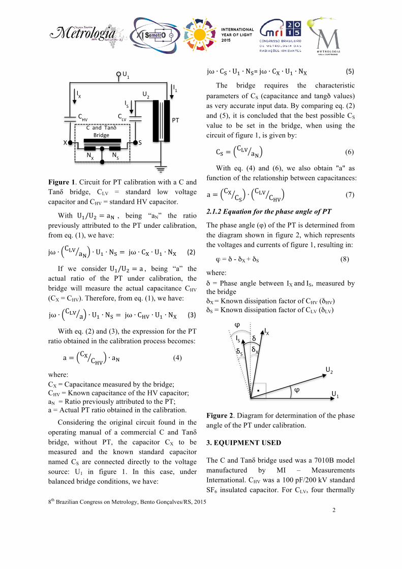
Figure 1. Circuit for PT calibration with a C and Tanδ bridge, CLV = standard low voltage capacitor and CHV = standard HV capacitor.
With U!/U! = a! , being “aN” the ratio previously attributed to the PT under calibration, from eq. (1), we have:
jω ∙ C!" a! ∙ U! ∙ N! = jω ∙ C! ∙ U! ∙ N! (2)
If we consider U!/U! = a , being “a” the actual ratio of the PT under calibration, the bridge will measure the actual capacitance CHV (CX = CHV). Therefore, from eq. (1), we have:
jω ∙ C!" a ∙ U! ∙ N! = jω ∙ C!" ∙ U! ∙ N! (3)
With eq. (2) and (3), the expression for the PT ratio obtained in the calibration process becomes:
a = C!C!" ∙ a! (4)
where: CX = Capacitance measured by the bridge; CHV = Known capacitance of the HV capacitor; aN = Ratio previously attributed to the PT; a = Actual PT ratio obtained in the calibration.
Considering the original circuit found in the operating manual of a commercial C and Tanδ bridge, without PT, the capacitor CX to be measured and the known standard capacitor named CS are connected directly to the voltage source: U1 in figure 1. In this case, under balanced bridge conditions, we have:
jω ∙ C! ∙ U! ∙ N!= jω ∙ C! ∙ U! ∙ N! (5)
The bridge requires the characteristic parameters of CS (capacitance and tangδ values) as very accurate input data. By comparing eq. (2) and (5), it is concluded that the best possible CS value to be set in the bridge, when using the circuit of figure 1, is given by:
C! =C!" a! (6)
With eq. (4) and (6), we also obtain "a" as function of the relationship between capacitances:
a = C!C! ∙ C!" C!" (7)
2.1.2 Equation for the phase angle of PT
The phase angle (φ) of the PT is determined from the diagram shown in figure 2, which represents the voltages and currents of figure 1, resulting in:
ϕ = δ - δX + δS (8)
where: δ = Phase angle between IX and IS, measured by the bridge δX = Known dissipation factor of CHV (δHV) δS = Known dissipation factor of CLV (δLV)
Figure 2. Diagram for determination of the phase angle of the PT under calibration.
3. EQUIPMENT USED
The C and Tanδ bridge used was a 7010B model manufactured by MI – Measurements International. CHV was a 100 pF/200 kV standard SF6 insulated capacitor. For CLV, four thermally
NX NS
U1
U2
PT CHV CLV
IX I1
X S
IS
C and Tanδ Bridge
φ
φ
δ δX δS
IS
U1
U2
IX
.

8th Brazilian Congress on Metrology, Bento Gonçalves/RS, 2015 3
stabilized [4] units of 1000 pF/750 V N2 insulated standard capacitors were available, allowing capacitances values of 1000 pF, 2000 pF, 3000 pF and 4000 pF. For the low voltage measurement of CHV and CLV and their respective dissipation factors (δHV and δLV), a high accurate capacitance meter AH2700A model, manufactured by Andeen-Hagerling, was used.
The standard PT calibrated during the implementation of the method was a NVRD40 PT model, manufactured by Epro. Nine PT taps were calibrated with rated voltages from 3kV to 40kV. The reasons for choosing this PT were: a) Up to its maximum voltage (40 kV), the variation of CHV due to its voltage coefficient is less than 1 ppm [2]; b) Its ratio values, combined with CHV and CLV available at Inmetro, enable measuring ranges at the bridge with low uncertainties; c) This PT was recently calibrated at PTB (2013), enabling comparison for validation purposes under equivalent conditions.
The C and Tanδ bridge was calibrated in Inmetro considering its best operating parameters that lead to minimum contribution to the uncertainty in the PT calibration results, based on the PT, CHV and CLV known characteristics. The circuit arrangement in the HV hall of Lamat is shown in figure 3.
4. CORRECTIONS AND UNCERTAINTIES
For metrological purposes, it must be considered that the temperature variation (△! ) and the applied voltage level (U) affect a capacitance (C).
Studies and experiments were performed in Inmetro for CHV and CLV capacitors in order to consider the effects of temperature and voltage either for correction purposes or for including them in the uncertainty of the results, together with the contribution due to the uncertainty of the capacitance bridge itself [3].
Figure 3. Circuit arrangement in the HV hall
of Lamat.
For the PT phase angle, corrections were applied in eq. (8) to consider the effects of stray capacitances and resistances between CHV and CLV capacitors and their respective inputs CX and CS in the bridge, as well as the correction of the bridge itself for dissipation factor measurement.
The uncertainty for phase angle result was estimated considering the uncertainties of the corrections and those related to the bridge: resolution, repeatability and its calibration for dissipation factor [3].
5. RESULTS
The results obtained by Inmetro for the PT calibration are shown in tables 1 and 2, together with information about the results obtained by PTB and those given by the manufacturer.
The maximum expanded uncertainty estimated by Inmetro in the PT calibration process was 0,0049 % for ratio error and 104 µrad for phase angle error. The PTB expanded uncertainty was 0,0040 % for ratio error and 44 µrad for phase angle error. The manufacturer gives 0,0050 % for ratio error and 145 µrad for phase angle error.
6. COMMENTS AND CONCLUSIONS
A method for internal metrological traceability of 60 Hz HVAC up to 40 kV, based on a circuit that
PT NVRD40
HV Source 250 kV
CHV
CLV

8th Brazilian Congress on Metrology, Bento Gonçalves/RS, 2015 4
uses a C and Tanδ bridge with two standard capacitors and a standard potential transformer, was successfully implemented in Inmetro.
By this method, the obtained results for PT ratio and phase angle are linked to the electrical resistance quantity (ohms), obtained from the quantum Hall effect in Inmetro.
The maximum estimated uncertainties obtained by Inmetro were 0,0049 % for ratio error and 104 µrad for phase angle error.
For the PT ratio, the results obtained by Inmetro, both error and uncertainty values, were in good agreement with those obtained by PTB.
Table 1. Discrepancies between Inmetro and PTB for ratio error (Δa) [x10-6] and phase angle (Δφ) [µrad].
Tap (%)
3 kV 15 kV 40 kV Δa Δϕ Δa Δϕ Δa Δϕ
40 00 04 00 -13 -02 -28 60 09 02 -01 -14 00 -26 80 09 -08 -02 -14 -02 -27
100 06 -08 -02 -15 -03 -29 120 07 -07 -03 -15 -03 -37
Table 2. Inmetro uncertainties for PT error in
ratio Ur(a) [x10-6] and phase angle Ur(φ) [µrad]. Tap (%)
3 kV 15 kV 40 kV Ur(a) Ur(ϕ) Ur(a) Ur(ϕ) Ur(a) Ur(ϕ)
40 25 104 46 104 36 104 60 26 104 46 104 36 104 80 26 104 46 104 37 104
100 28 104 47 104 38 104 120 30 104 49 104 41 104
For phase angle, the uncertainty values of Inmetro can be considered acceptable when compared with those given by the PT manufacturer, but they exceeded by more than twice the PTB ones. This was consequence of the higher uncertainty obtained by Inmetro when calibrating the bridge for dissipation factor.
8. REFERENCES
[1] William E. Anderson, “NBS Measurement services: A calibration service for voltage transformers and HV capacitors”, NBS (U.S.) Special Publication 250-33, Jun. 1988.
[2] H. G. Latzel, K. Schon, “Precise Capacitance Measurements of HV compressed Gas Capacitors”, IEEE/TIM, Vol. IM-36, No. 2, Jun. 1987.
[3] Vladimir R. de Lima et al., “Implementation of a HV Primary Standard Method using a Capacitance Bridge”, CPEM, Rio de Janeiro, Aug. 2014.
[4] G.A. Kyriazis and J. Melcher, “Thermally-controlled gas-dielectric standard capacitors constructed at Inmetro”, Proc. CEPEM, pp. 560-561, Broomfield, USA, Aug. 2008.
ACKNOWLEDGMENTS
The authors would like to thank Dr. Renata T. de Barros e Vasconcellos, head of the Inmetro’s Electrical Standardization Metrology Laboratory, for her assistance with technical discussions and laboratory work on calibrations of the CLV and the C and Tanδ bridge, and the technical staff of Lamat for the support.


![Guide to Quality in Analytical ChemistryFor those working in microbiology, it should be noted that Eurachem has ... measurement uncertainty and metrological traceability [12-14]. This](https://static.fdocuments.in/doc/165x107/611313175017ee252a72680b/guide-to-quality-in-analytical-chemistry-for-those-working-in-microbiology-it-should.jpg)
