Development of Robust Metal Membranes for Hydrogen Separation
Upload
samuel-maguire-boyleCategory
view
53download
2
US 20120261343A1
(19) United States (12) Patent Application Publication (10) Pub. No.: US 2012/0261343 A1
Barron et al. (43) Pub. Date: Oct. 18, 2012
(54)
(75)
(73)
(21)
(22)
(51)
METHODS, SYSTEMS AND MEMBRANES FOR SEPARATION OF ORGANIC COMPOUNDS FROM LIQUID SAMPLES
Inventors: Andrew R. Barron, Houston, TX (US); Samuel J. Maguire-Boyle, Drogheda (IE)
Assignee: WILLIAM MARSH RICE UNIVERSITY, Houston, TX (US)
Appl. No.: 13/087,706
Filed: Apr. 15, 2011
Publication Classi?cation
Int. Cl. C02F 1/44 (2006.01) B01D 71/02 (2006.01) B01D 71/06 (2006.01) B05D 5/00 (2006.01) B01D 71/00 (2006.01) B01D 71/04 (2006.01) C02F 101/32 (2006.01)
(52) US. Cl. 210/651; 210/650; 210/435; 210/500.21; 210/500.25; 210/500.26; 210/500.33; 210/500.37;
427/585; 427/245
(57) ABSTRACT
Various aspects of the present invention pertain to porous membranes that comprise: (1) a plurality of pores With pore siZes of more than about 0.1 pm in diameter; and (2) a plu rality of hydrophilic molecules. Additional aspects of the present invention pertain to methods of separating organic compounds from a liquid sample by: (1) providing the porous membrane; and (2) ?owing the liquid sample through the porous membrane in order to retain organic compounds on the porous membrane. Further aspects of the present inven tion pertain to systems for separating organic compounds from a liquid sample. Such systems comprises: (1) the porous membrane; and (2) a ?owing unit that enables the liquid sample to How through the porous membrane. Additional aspects of the present invention pertain to methods of making the above-described porous membranes by: (1) coating a surface of a porous membrane containing 0.1 pm pores With a ceramic material; and (2) associating the coated surface of the porous membrane With hydrophilic molecules.

Patent Application Publication Oct. 18, 2012 Sheet 1 0f 12 US 2012/0261343 A1
F33. ‘i

Patent Application Publication Oct. 18, 2012 Sheet 2 0f 12 US 2012/0261343 A1
2%
F36, Q
Patent Application Publication Oct. 18, 2012 Sheet 3 0f 12 US 2012/0261343 A1
Patent Application Publication Oct. 18, 2012 Sheet 4 0f 12 US 2012/0261343 A1
FIG. 3

Patent Application Publication Oct. 18, 2012 Sheet 5 0f 12 US 2012/0261343 A1
HQ. 4

Patent Application Publication
aw
Oct. 18, 2012 Sheet 6 0f 12 US 2012/0261343 A1
Fig‘ 5

Patent Application Publication Oct. 18, 2012 Sheet 7 0f 12 US 2012/0261343 A1
?aiiwwiiit
Fi'Gi
Patent Application Publication Oct. 18, 2012 Sheet 8 0f 12 US 2012/0261343 A1

Patent Application Publication Oct. 18, 2012 Sheet 9 0f 12 US 2012/0261343 A1
HQ 3

Patent Application Publication Oct. 18, 2012 Sheet 10 0f 12 US 2012/0261343 A1

Patent Application Publication Oct. 18, 2012 Sheet 11 0f 12 US 2012/0261343 A1
Largys»; paw saim Swazi? gmr'e
f wmw A?” w ?ydwgamm % n'sembnzma wig-Wang
&
m~.@ 0%.
. g

Patent Application Publication Oct. 18, 2012 Sheet 12 0f 12 US 2012/0261343 A1
3G8‘; 355* Tami? gamma : Q Ta'iaiimgmis mmrm
m3“; 11*? imrga?k; swam ijjaam}
Camaxzim?an WM} 165?
384i
iFiiG. ‘i ‘i

US 2012/0261343 A1
METHODS, SYSTEMS AND MEMBRANES FOR SEPARATION OF ORGANIC
COMPOUNDS FROM LIQUID SAMPLES
STATEMENT REGARDING FEDERALLY SPONSORED RESEARCH
[0001] This invention Was made With government support under US. Navy Grant No. N61331-08-1-G001, awarded by the US. Department of Defense. The Government has certain rights in the invention.
BACKGROUND OF THE INVENTION
[0002] The development of neW methods and systems for separating organic compounds from various liquid samples is important in many industries, including the oil and gas indus try. Current methods and systems for separating organic com pounds from liquid samples suffer from various limitations. Such limitations include loW liquid ?oW rates, membrane blockage, and the need to use multiples layers of membranes. Therefore, there is currently a need to develop neW methods, systems and membranes for separating organic compounds from liquid samples.
BRIEF SUMMARY OF THE INVENTION
[0003] In some embodiments, the present invention pro vides improved porous membranes for separating organic compounds (e.g., hydrocarbons) from liquid samples (e.g., saltwater). Such porous membranes generally comprise: (1) a plurality of pores With pore siZes of more than about 0.1 pm in diameter (e.g., 0.14 pm); and (2) a plurality of hydrophilic molecules (e.g., cysteic acid). Additional aspects of the present invention pertain to methods for separating organic compounds from a liquid sample. Such methods generally comprise: (1) providing the above-described porous mem brane; and (2) ?oWing the liquid sample through the porous membrane to retain organic compounds on the porous mem brane. In some embodiments, the ?oWing step may also include a ?ltration step. In some embodiments, the method may reduce the carbon content of the liquid sample (e.g., beloW about 7 ppm). [0004] Other embodiments of the present invention pertain to systems for separation of organic compounds from a liquid sample. Such systems generally comprise: (1) the above described porous membrane; and (2) a ?oWing unit that enables the liquid sample to How through the porous mem brane. In some embodiments, the ?oWing unit also comprises a ?ltration unit. In some embodiments, the ?oWing unit houses the porous membrane. [0005] Additional embodiments of the present invention pertain to methods of making the above-described porous membranes. Such methods generally comprise: (1) coating a surface of a porous membrane containing 0.1 pm pores (or larger pores) With a ceramic material; and (2) associating the coated surface of the porous membrane With hydrophilic molecules. [0006] Further embodiments of the present invention per tain to additional methods of making the above-described porous membranes. Such methods generally comprise asso ciating the surface of a porous membrane containing 0.1 pm pores (or larger pores) With hydrophilic molecules. [0007] As set forth in more detail beloW, the methods, membranes and systems of the present invention provide numerous improvements in separating various organic com
Oct. 18, 2012
pounds from liquid samples. In addition, it is envisioned that the methods, membranes and systems of the present invention can provide various improved applications, including the treatment of oil-contamined sea Water and the puri?cation of frac Water.
BRIEF DESCRIPTION OF THE FIGURES
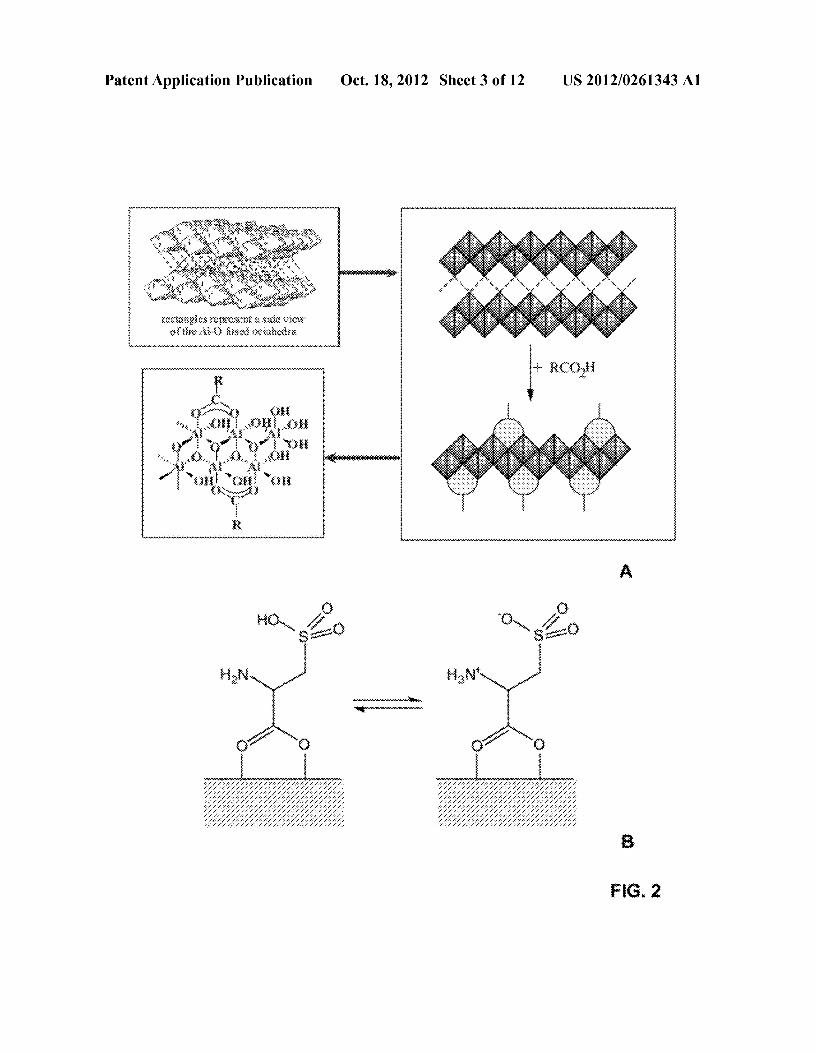
[0008] In order that the manner in Which the above recited and other advantages and objects of the invention are obtained, a more particular description of the invention brie?y described above Will be rendered by reference to spe ci?c embodiments thereof, Which are illustrated in the appended Figures. Understanding that these Figures depict only typical embodiments of the invention and are therefore not to be considered limiting of its scope, the invention Will be described With additional speci?city and detail through the use of the accompanying Figures in Which: [0009] FIG. 1 depicts various systems for separation of organic compounds from liquid samples, in accordance With speci?c embodiments of the present invention. [0010] FIG. 1A depicts top vieWs of various systems 10 shoWing ?oWing units 12 that house porous membranes 14. [0011] FIG. 1B depicts cross-sectional vieWs of systems 10. [0012] FIG. 1C depicts an alternative system 20 for sepa ration of organic compounds from liquid samples. In this embodiment, system 20 also contains a ?ltration unit 23 Within ?oWing unit 22 that houses porous membrane 24. [0013] FIG. 2 depicts various aspects of exemplary porous membranes. [0014] FIG. 2A depicts a process for making a porous membrane in accordance With some embodiments of the present invention. In this embodiment, alumina-coated silica Wafers are functionaliZed With carboxylic acids. [0015] FIG. 2B depicts a cross-sectional vieW of a porous membrane containing a cysteic acid as a hydrophilic mol ecule. The cysteic acid is shoWn in its neutral and ZWitterionic states.
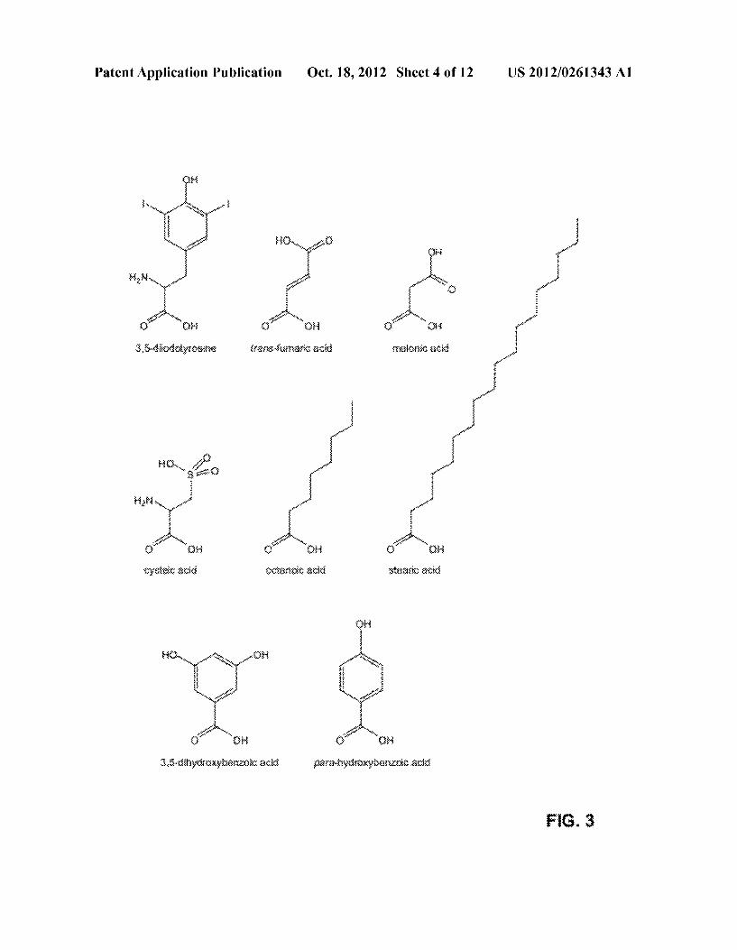
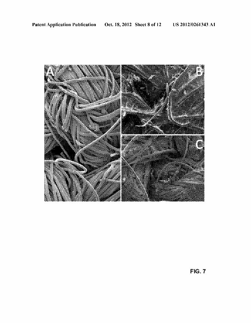
[0016] FIG. 3 shoWs the structure of various hydrophilic molecules that could be utiliZed to functionaliZe the porous membranes of the present invention in various embodiments. [0017] FIG. 4 shoWs data relating to the characterization of a cysteic acid functionaliZed alumoxane porous memrane. [0018] FIG. 4A shoWs thermographic analysis (TGA) data relating to the porous membrane. [0019] FIG. 4B shoWs a transmission electron microscopy (TEM) image of the porous membrane. [0020] FIG. 5 shoWs comparative X-ray diffraction (XRD) patterns of bohemite (red) and a cysteic acid functionaliZed alumoxane porous memrane (blue). [0021] FIG. 6 shoWs contact angle measurements for Water on various alumina porous membrane surfaces that Were functionaliZed With various carboxylic acids. [0022] FIG. 7 shoWs scanning electron microscopy (SEM) images of alumoxane coated Nomex® membranes treated under various conditions. [0023] FIG. 7A is an SEM image of an unfunctionaliZed Nomex® membrane. [0024] FIG. 7B is an SEM image of an alumoxane coated Nomex® membrane that has been functionaliZed With cysteic acid. [0025] FIG. 7C is an SEM image of the Nomex® mem brane in FIG. 7B after heat treatment.

US 2012/0261343 A1
[0026] FIG. 8 shows the aggregation size pattern of cysteic acid functionaliZed alumoxane porous memranes that Were dried under different pH levels. [0027] FIG. 9 shoWs the total organic carbon (TOC) mea surements of various types of Nomex membranes. Type A is untreated Nomex, Type B is Nomex dip-coated in a cysteic acid functionaliZed alumoxane nanoparticle solution, and Type C is Nomex dip-coated in cysteic acid functionaliZed alumoxane and heated to partially convert to a ceramic coat mg. [0028] FIG. 10 shoWs a representation of the tWo problems associated With separation of hydrocarbons from Water. [0029] FIG. 10A shoWs that, When a membrane With a large pore siZe is used (e.g., ~1 um), then the membrane cannot separate the hydrocarbon molecules from Water. [0030] FIG. 10B shoWs that, When the membrane pore siZe is small enough to alloW separation of hydrocarbons from Water (e.g., ~5 nm), then the pores become blocked by the hydrocarbons or other materials in the mixture. In addition, a high pressure may be required, and the How may be loW. [0031] FIG. 11 shoWs a plot of the total carbon, total organic carbon, and calculated inorganic carbon for a sample of frac (production) Water before ?ltration With a 0.14 pm membrane. Corresponding data for the concentrate and the permeate are also shoWn.
DETAILED DESCRIPTION OF EXEMPLARY EMBODIMENTS
[0032] It is to be understood that both the foregoing general description and the folloWing detailed description are exem plary and explanatory only, and are not restrictive of the invention, as claimed. In this application, the use of the sin gular includes the plural, the Word “a” or “an” means “at least one”, and the use of “or” means “and/or”, unless speci?cally stated otherWise. Furthermore, the use of the term “includ ing”, as Well as other forms, such as “includes” and “included”, is not limiting. Also, terms such as “element” or “component” encompass both elements or components com prising one unit and elements or components that comprise more than one unit unless speci?cally stated otherWise. [0033] The section headings used herein are for organiZa tional purposes only and are not to be construed as limiting the subject matter described. All documents, or portions of documents, cited in this application, including, but not lim ited to, patents, patent applications, articles, books, and trea tises, are hereby expressly incorporated herein by reference in their entirety for any purpose. In the event that one or more of the incorporated literature and similar materials de?nes a term in a manner that contradicts the de?nition of that term in this application, this application controls. [0034] By Way of background, oily WasteWaters are an inconvenient byproduct of many industries. Ratios of hydro carbon/Water emulsions vary greatly from industry to indus try. Nonetheless, oily WasteWater represents a signi?cant environmental haZard that cannot be easily assuaged. Fur thermore, oily WasteWater results in a signi?cant economic drain, especially since the Water must be cleaned up prior to use. Many techniques exist for the separation of these emul sions, although all have signi?cant drawbacks to consider. See, e.g., FIG. 10. [0035] For instance, in recent years, membrane ?ltration has been shoWn to be one of the best methods for large scale separation of oily WasteWaters. This is due to processing factors, such as recyclability of throughput material in cross
Oct. 18, 2012
How membrane assemblies, ease of cleaning, as Well as highly pure permeate With no chemical tainting. A signi?cant draWback of membrane puri?cation is membrane fouling, Which can be due to a number of factors, such as adsorption inside the membrane, deposition on the membrane surface to form a cake layer, and blocking of the membrane pores. See, e.g., FIG. 10B.
[0036] Hydrophilic membranes have been shoWn to achieve anti-fouling properties. In fact, in many Ways, hydro philic membranes are preferable over hydrophobic mem branes. Without being bound by theory, it is envisioned that such properties are due to hydrophilic membranes being less sensitive to adsorption.
[0037] Accordingly, several methods, such as surface seg regation, surface coating, and surface graft polymerization, have been utiliZed to enhance surface hydrophilicity in order to control the antifouling properties of membrane materials. HoWever, many of these methods suffer from various limita tions. For instance, ceramic membranes offer good commer cialiZable methods for separation. HoWever, traditionally, ceramic membranes require very small pores (<10 nm) for oil/Water separation. Such small pore siZes may decrease ?uid ?oW rate and cause clogging.
[0038] To overcome problems With decreased ?oW rate and clogging, the use of large membranes or high pressure may be required. Another method to overcome these problems is through a back-?ush of the permeate in order to declog the membrane. HoWever, such methods are only partially effec tive and present many technical burdens.
[0039] Furthermore, membranes With small pore siZes present additional issues. Generally, the use of membranes With small pore siZes for Water puri?cation requires an arrangement of multiple layers With different pore siZes. Such arrangements may lead to additional clogging problems. Such arrangements may also be expensive. [0040] To address the aforementioned problems, one aspect of the present disclosure provides methods of separat ing organic compounds (e.g., hydrocarbons) from a liquid sample (e.g., saltWater). Such methods generally comprise: (1) providing a porous membrane With pore siZes of more than about 0.1 pm in diameter (e.g., 0.14 pm) that has been functionaliZed With hydrophilic molecules (e.g., cysteic acid); and (2) ?oWing the liquid sample through the porous membrane.
[0041] Other embodiments of the present invention pertain to systems for separation of organic compounds from a liquid sample. Such systems generally comprise: (1) a porous mem brane as described; and (2) a ?oWing unit that enables the liquid sample to How through the porous membrane. Addi tional embodiments of the present invention pertain to the above-described porous membranes and methods of making them.
[0042] Speci?c examples of systems in accordance With various embodiments of the present invention are depicted in FIGS. 1A-1C. For instance, in the speci?c embodiments shoWn in FIGS. 1A-1B, systems 10 contain multiple ?oWing units 12. The ?oWing units house porous membranes 14 on their internal cavity Walls (not shoWn). Porous membranes 14 in these embodiments have pores With pore siZes of about 0.14 pm in diameter. In addition, the porous membranes are functionaliZed With cysteic acid molecules. [0043] In operation, liquid samples containing organic compounds ?oW through ?oWing units 12 in systems 10. This

US 2012/0261343 A1
results in the retainment of organic compounds on porous membranes 14 and the release of the remaining liquid sample. [0044] In another speci?c embodiment shoWn in FIG. 1C, system 20 contains a ?owing unit 22 that also contains a ?ltration unit 23, Which houses porous membrane 24 (not shoWn). In operation, liquid samples containing organic com pounds ?oW through ?oWing unit 22, ?ltration unit 23, and porous membrane 24. The porous membrane retains organic compounds and releases the remaining liquid sample. [0045] The aforementioned embodiments Will noW be dis cussed in more detail beloW. Various aspects of the methods, systems and porous membranes of the present disclosure Will also be discussed With more elaboration beloW as speci?c and non-limiting examples. [0046] Separation Systems [0047] The systems of the present invention are designed for the separation of organic compounds from various liquid samples. Such systems generally comprise: (l) a porous membrane; and (2) a ?oWing unit that enables the liquid sample to How through the porous membrane. [0048] Porous Membranes [0049] In general, the porous membranes of the present invention comprise: (1) multiple pores With pore siZes of more than about 0.1 pm in diameter; and (2) multiple hydro philic molecules. The porous membranes of the present invention may be derived from various sources. For instance, in some embodiments, the porous membranes are derived from a ceramic material. In more speci?c embodiments, the porous membranes are ceramic membranes derived from alu mina (e.g., Al2O3), titania (TiO2), and/or Zirconia (ZrOZ). HoWever, the use of other ceramic membranes can also be envisioned by persons of ordinary skill in the art. [0050] In more speci?c and preferred embodiments, porous membranes of the present invention are derived from alumox ane. In further preferred embodiments, porous membranes of the present invention are supported by a Nomex® fabric. In more speci?c embodiments, the porous membrane is a silica Wafer coated With alumina. Other suitable porous membranes can also be envisioned by persons of ordinary skill in the art. [0051] The porous membranes of the present invention can be associated With numerous hydrophilic molecules. Non limiting examples of such hydrophilic molecules include car boxylic acids, acidic molecules, basic molecules, ZWiterri onic molecules, phenyl amines, phenyl amidines (e.g., 1,3 diphenylamidine), amino pyridines (e. g., methylaminopyridine), and combinations thereof. In some embodiments, the porous membranes of the present invention may be associated With more than one hydrophilic molecule.
[0052] In more speci?c and preferred embodiments, the hydrophilic molecules associated With the porous membranes are carboxylic acids. In some embodiments, the carboxylic acid has the general formula RCOZH, Where R is a hydro philic functional group. Exemplary carboxylic acids include, Without limitation, cysteic acid, 3,5-diiodotyrosine, trans fumaric acid, malonic acid, octanoic acid, stearic acid, 3,5 dihydroxybenZoic acid, parahydroxy benZoic acid, and com binations thereof. See FIG. 3. In more speci?c and preferred embodiments, the hydrophilic molecules on the porous mem branes are cysteic acid. [0053] The porous membranes of the present invention may also have pores of various siZes. In some embodiments, the pore siZes in the porous membrane may range from about 0.1 pm in diameter to above 10 um in diameter. In other embodi ments, the pore siZes may range from about 0.1 pm in diam
Oct. 18, 2012
eter to about 1 um in diameter. In other embodiments, the pore siZes are about 0.14 pm in diameter to about 1.4 pm in diam eter. In other embodiments, the pore siZes may be greater than about 10 um. Other suitable pore siZes can also be envisioned.
[0054] The porous membranes of the present invention may have various shapes and forms. For instance, in some embodi ments, the porous membrane may consist of multiple layers (e.g., 2-8 layers, in some embodiments.) Likewise, in some embodiments, the porous membranes may be cylindrical (e.g., porous membrane 14 in FIGS. 1A-1B), ?at (e.g., porous membrane 24 in FIG. 1C), or circular. In more speci?c embodiments, porous membranes may be in the form of nanoparticles. [0055] In further embodiments, the porous membranes of the present invention may be about 2.5 cm in diameter and about 12 cm in length. In other embodiments, the membrane may be about 1 meter in length and about 4 meters in diam eter.
[0056] Referring noW to FIG. 2A, an exemplary porous membrane is shoWn. In this example, the porous membrane is an alumoxane-based porous membrane that has been func tionaliZed With a carboxylic acid. FIG. 2B illustrates the association of the carboxylic acid With the membrane in more detail. In this embodiment, the carboxylic acid is cysteic acid in ZWitterionic and neutral forms.
[0057] FloWing Units [0058] In various embodiments, the systems of the present invention may also be associated With ?oWing units. As used herein, ?owing units generally refer to spaces or structures that enable a liquid sample to How through a porous mem brane. Such ?oWing units can have various shapes, structures and forms. Non-limiting examples of ?oWing units are shoWn as ?oWing units 12 and 22 in FIGS. 1A-1C.
[0059] In some embodiments, the ?oWing units of the present invention may also comprise or be associated With a ?ltration unit. A non-limiting example is ?oWing unit 22 in FIG. 1C, Which is associated With a ?ltration unit 23. In some embodiments, the ?oWing unit containing the ?ltration unit may be a Nalgene ?ltration cell.
[0060] In further embodiments, the ?oWing unit houses the porous membrane. Examples are again shoWn in FIGS. 1A-1C, Where ?oWing units 12 and 22 house porous mem branes 14 and 24, respectively. Other suitable ?oWing units can also be envisioned by persons of ordinary skill in the art.
[0061] In additional embodiments, the ?oWing units of the present invention may also be associated With additional components for enhanced liquid ?oW. Such components can include pumps, pipes, vacuums, and/or valves. The arrange ment, use and structure of such components are Well knoWn to persons of ordinary skill in the art.
[0062] Methods of Separating Organic Compounds from Liquid Samples [0063] Other aspects of the present invention pertain to methods for separating organic compounds from a liquid sample. Such methods generally include: (1) providing a porous membrane With 0.1 pm pore siZes and hydrophilic functional groups (as described); and (2) ?oWing the liquid sample through the porous membrane to retain organic com pounds on the porous membrane. Other methods may only include ?oWing a liquid sample through the above-described porous membrane in order to retain organic compounds on the porous membrane. Such methods result in the puri?cation of the liquid sample.

US 2012/0261343 A1
[0064] In some embodiments, a substantial portion of the organic compounds in the liquid sample are retained on the porous membrane (e.g., 50-60%). In other embodiments, loWer portions of the organic compounds may be retained (e.g., 15-20%). [0065] The separation methods of the present invention can have various embodiments. For instance, various porous membranes (as previously described) may be utiliZed. Like Wise, various ?owing steps may be utiliZed. [0066] FloWing Steps [0067] In general, the ?oWing step involves ?oWing a liquid sample through a porous membrane by placing the liquid sample in contact With the porous membrane. In some embodiments, this may occur by passive How of the liquid sample. In further embodiments, the ?oWing may be initiated or enhanced by a pump or other mechanical apparatus. In further embodiments, the ?oWing step may involve a ?ltration step. [0068] Other ?oWing steps can also be envisioned by per sons of ordinary skill in the art. For instance, in some embodi ments, the separation methods of the present invention may use one or more carboxylic acid functionaliZed ceramic porous membranes that are mounted in a suitable separation system to alloW cross-?ow ?ltration and/or separation of a permeate containing Water With solids and organic matter. [0069] Methods of Making Porous Membranes [0070] Additional embodiments of the present invention pertain to methods of making the above-described porous membranes. Such methods generally comprise: (1) coating a surface of a porous membrane that contain pore siZes of more than about 0.1 pm in diameter With a ceramic material (as previously described); and (2) associating the coated surface of the porous membrane With hydrophilic molecules (as also previously described). In some embodiments, the ceramic material is alumina. In some embodiments, the coating occurs by electron beam deposition methods that are Well knoWn to persons of ordinary skill in the art. In some embodiments, the hydrophilic molecule is a carboxylic acid, such as cysteic acid. [0071] In further embodiments of the present invention, the method may further comprise a step of drying the coated surface of the porous membrane. In some embodiments, the drying occurs by heat treatment. In further embodiments, the drying occurs under acidic conditions (e.g., pH of about 2). [0072] Further embodiments of the present invention per tain to additional methods of making the above-described porous membranes. Such methods generally comprise asso ciating the surface of a porous membrane containing 0.1 pm pores (or larger pores) With hydrophilic molecules. [0073] FIG. 2A depicts an exemplary method of making a porous membrane. In this example, a porous membrane is coated With alumina. This is folloWed by functionaliZation With a carboxylic acid. Other methods of making porous membranes can also be envisioned by persons of ordinary skill in the art.
Applications
[0074] The systems, membranes and methods of the present invention can be used to separate various organic compounds from various liquid samples. For instance, in some embodiments, organic compounds to be separated are hydrocarbons, such as crude oil. In some embodiments, the liquid sample may be saltWater, such as ocean Water con tamined With crude oil from an oil spill.
Oct. 18, 2012
[0075] Another application of the systems, membranes and methods of the present invention is the puri?cation of sea Water. By Way of background, reverse osmosis has been a general method for desalination (removal of salt) from sea Water. Unfortunately, the desalination resins are very suscep tible to organic and biological matter that rapidly destroy the usefulness of the system. Using the present invention, sea Water can be easily and cheaply puri?ed of organic and bio logical material in order to make the desalination process more economically viable.
[0076] Other application of the present invention include the separation of polymers and inorganic materials from Water. Such separation methods can ?nd applications in numerous industrial processes.
[0077] In other embodiments, the systems, membranes and methods of the present invention may be used to purify frac Water, such as frac Water resulting from the hydraulic fractur ing of gas containing shale reservoirs. Such applications of the present invention can be bene?cial, especially in vieW of declining Well production per acre surface density (number of Wells per acre) and increases in frac Water usage (as much as 1,000,000 gallons per Well). In particular, the methods and systems of the present invention can be used to purify post production frac Water to remove organic contaminants. Such puri?ed Water can be re-introduced into the environment or re-used for additional frac-ing.
Advantages
[0078] Overall, the systems, membranes and methods of the present invention can be utiliZed to reduce the carbon content of various liquid samples. For instance, in some embodiments, the methods of the present invention may be used to reduce the carbon content of liquid samples to beloW about 7 ppm. As discussed beloW, such results provide various advantages over the systems, membranes and methods of the prior art. [0079] For instance, as discussed in more detail beloW, the experimental data shoW that the use of ceramic membranes of the present invention reduces the pump pres sure required for a particular ?ux from about 6-7 bar to about 2-3 bar. More importantly, the How of permeate does not decrease over time due to minimal fouling. Furthermore, the methods and sys tems of the present invention may utiliZe porous membranes made of only one or tWo layers to accomplish the same results as the multi-layer systems of the prior art. Such applications also simplify the construction of the membrane, both in terms of technical and ?nancial aspects. [0080] While it is knoWn that ceramic surfaces can be func tionaliZed by carboxylic acids to alterperrneate ?ux (speed of How), Applicants are unaWare of any prior art that such func tionaliZation can be designed to alloW a >0.1 um membrane to separate organic materials from liquid samples. In contrast, prior art methods utiliZed nanometer pore siZed membranes that presented many problems. In addition, there is no prior art to indicate that surface functionaliZation Would provide a barrier to organic and biological matter. [0081] An additional surprising result of this invention is that taking production Water from a gas Well that contains both inorganic particulates may be ?ltered to beloW 7 ppm total carbon content by passing the Water through a 0.14 pm membrane in one pass. Analysis shoWs that the carbon con

US 2012/0261343 A1
tent of the puri?ed Water is predominantly carbonate rather than organic material that cannot be detected.
Additional Embodiments
[0082] From the above disclosure, a person of ordinary skill in the art Will recognize that the methods and systems of the present disclosure can have numerous additional embodi ments. Reference Will noW be made to more speci?c embodi ments of the present disclosure and experimental results that provide support for such embodiments. However, Applicants note that the disclosure beloW is for exemplary purposes only and is not intended to limit the scope of the claimed invention in any Way.
EXAMPLES
[0083] Additional details about the experimental aspects of the above-described studies are discussed in the subsections beloW. In the Examples beloW, the fabrication of surface functionaliZed alumina fabric composite membranes using hydrophilic cysteic acid surface stabiliZed alumina nanopar ticles (alumoxanes) Were investigated. Contact angle mea surements for a range of carboxylic acids functionaliZed onto alumina coated silicon Wafers Were also investigated to deter mine the functionaliZation that results in the mo st hydrophilic surfaces. [0084] Highly porous Nomex® fabric Was utiliZed as a membrane support for an alumoxane nanoparticle derived membrane ?lter. This ?lter Was used for the ?ux differentia tion studies of heavy hydrocarbons from Water, and the sepa ration of oil/Water emulsions. Coating techniques utiliZing pH control Was also investigated. Retention coef?cients and ?ux values indicate that surface chemistry of the fabric may be altered by coating With chemically functionaliZed alumina nanoparticles to provide selective How of Water versus hydro carbons. [0085] In broader terms, the study beloW involved the screening of hydrophilic membrane surfaces using static Water contact angle measurement. The study beloW also uti liZed the application of fabric supported membranes for dif ferentiation of ?ux rates for Water and hydrocarbons With a vieW to its application in oil/Water separation.
Example 1
[0086] Pseudoboehmite Was provided by Sasol North America Inc. All carboxylate acids Were obtained commer cially (Aldrich) and Were used as received. Nalgene ?ltration cells (#300-4000) Were obtained from Fisher Scienti?c. Nomex® fabric Was obtained from Pegasus Auto Racing Supplies, Inc. [0087] EDX studies Were performed on a Hitachi HD-2700 STEM scanning microscope. The samples Were attached to a metal mount using carbon tape. A thin layer of gold Was sputtered onto the samples to provide a conducting surface. Thermogravimetric/ differential thermal analyses (TG/DTA) Were obtained on a Q-600 Simultaneous TGA/DSC TA Instruments using a carrier gas of either dry nitrogen or air. SEM microscopy studies Were performed on a FEI Quanta 400 ESEM. A thin layer of gold Was sputtered onto the samples to provide a conducting surface. The samples Were mounted on carbon tape and sputter coated With gold. TEM microscopy studies Were performed on a J eol 1230 HC-TEM
Oct. 18, 2012
120 kV. XPS studies Were conducted on a PHI Quantera XPS machines. XRD studies Were conducted on Rigaku D/Max Ultima II XRD machine. [0088] Using a modi?cation of the literature method (C. T. Vogelson,A. Keys, C. L. EdWards, andA. R. Barron, Molecu lar coupling layers formed by reactions of epoxy resins with self-assembled carboxylate monolayers grown on the native oxide of aluminum, J. Mater. Chem., 13 (2003)291-296), silicon Wafers Were coated With a thin layer of alumina (100 nm) via e-beam deposition. In order to remove impurities on the alumina surface, the coated Wafers Were dipped in a 1:1 solution of conc. H2SO4 and 30% H2O2 for 5 min. The Wafer Was then Washed With 2-propanol and air dried. The alumina coated silica Wafer Was then gently re?uxed at various tem peratures depending on the functionaliZing carboxylic acid. After the reaction Was completed, the Wafers Were Washed With IPA and air dried. Table 1 beloW and FIG. 3 provide summaries of reaction conditions for carboxylic acid func tionaliZation of alumina surfaces.
TABLE 1
Summary of reaction conditions for carboxylic acid functionalization of alumina surfaces.
Vol- Molar- Temper Carboxylic Mass ume ity ature Reaction acid (g) Solvent (mL) (M) (O C.) time (h)
3,5-diiodo- 1.87 DMSO 20 0.1 160 24 tyrosine trans-furnaric 2.32 EtOH 40 0.5 60 24 acid malonic acid 2.08 H20 40 0.5 105 24 cysteic acid 3.74 H20 40 0.5 105 24 octanoic acid 2.90 DMSO 40 0.5 160 24 stearic acid 1.14 CHCl3 40 0.1 61 24 3,5-dihydroxy- 3.08 DMSO 40 0.5 160 24 benzoic acid para-hydroxy- 2.76 DMSO 40 0.5 160 24 benzoic acid
Synthesis of Cysteic Acid Alumoxane
[0089] In a modi?cation of the literature procedures (R. L. Callender, C. J. Harlan, N. M. Shapiro, C. D. Jones, D. L. Callahan, M. R. Wiesner, R. Cook, andA. R. Barron, Aqueous synthesis of Water soluble alumoxanes: environmentally benign precursors to alumina and aluminum-based ceramics, Chem. Mater., 9 (1997) 2418-2433; R. L. Callender andA. R. Barron, Facile synthesis of aluminum containing mixed metal oxides using doped carboxylate-alumoxane nanoparticles, J. Am. Ceram. Soc., 83 (2000) 1777; N. Shahid and A. R. Barron, Solvent free synthesis of carboxylate-alumoxane nanoparticles using mechanical shear, J. Mater. Chem., 14 (2004)1235-1237), pseudoboehmite (100 g) Was vigorously stirred in DI H20 (80 mL). To this solution Was sloWly added an aqueous 1 M solution of cysteic acid (80 mL). The result ing solution Was alloWed to stir overnight, and then centri fuged at 4500 rpm for 1 hour. The ceramic yield (55%) and the average particle siZe (17 nm) Were determined by TGA and TEM, respectively. See FIGS. 5-6. The hydrated solid Was used in future dip coatings of Nomex material [0090] Nomex® fabric (18 cm2) Was Washed sequentially With EtOH and acetone to remove excess dye and surface contaminants. The fabric Was then vacuum-dried and then dip-coated in a 20 Wt % aqueous solution of cysteic acid

US 2012/0261343 A1
alumoxane solution (10 g in 50 mL DI H20) and heldthere for 2-5 seconds. The dip-coat Was allowed to oven dry (100° C.) before repeating the procedure. The fabric Was loaded With 5 g of cysteic acid alumoxane per 18 cm2. See FIG. 7.
[0091] Retention Studies by Gravity Filtration [0092] The cysteic acid functionalized alumoxane Nomex composite membrane Was cut to 5.5 cm diameter circle and ?tted into the Nalgene ?ltration cell. The desired solution/ emulsion (250 mL) Was poured on top of the mounted sup port. The concentration of the initial feed Was compared to the concentration of permeate overtime to determine the percent age of retention. Initially, this Was achieved through inspec tion for larger MW hydrocarbons. For smaller Weight hydro carbons (including Dextrans), GC-mass spectral analysis Was used. This methodology Was used for all solution studies presented herein. [0093] Previous Work suggested that para-hydroxybenzoic acid functionalization Would make an alumina surface slightly more hydrophilic. The initial goal Was to compare a range of functional carboxylic acids. Each of the carboxylic acids Were functionalized onto the alumina coated silica Wafers to alloW for ready comparison by contact angle mea surements. The surfaces Were tested using goniometer con tact angle techniques. From this it Was observed that cysteic acid functionalized alumina coated Wafers Were extremely hydrophilic, achieving complete Wetability When in contact With Water. See FIGS. 2A-2B. Without being bound by theory, it is envisioned that such hydrophilic attributes Were due to the hydrogen bonding abilities of both sulfonyl and amine moieties on functionalized cysteic acid and its zWitte rionic adducts. See FIG. 2B. Based on these results, cysteic acid Was chosen as the preferred candidate for the creation of hydrophilic alumoxane Nomex composite membranes. [0094] Deposition of zWitterionic polymers has been uti lized in previous Work by other groups. HoWever, deposition of a polymer onto a surface is dif?cult to control. Further more, polymers are susceptible to degradation. Moreover, polymer deposition is prone to exponential loss in hydrophi licity When degradation occurs. By placing a zWitterionic molecule onto the surface of a inorganic nanoparticle, many advantages are achieved. Such advantages include the control of deposition and subsequent controlled coating of Nomex ?bers. Degradation of hydrophilicity is also lessened by com parison to polymerization due to the functionalization being solely molecular. This ensures that loss of the zWitterionic molecule from a nanoparticle does not mean a loss of hydro philicity of that nanoparticle. [0095] In the above-described studies, cysteic acid Was uti lized as the zWitterionic molecule. The dissociation constant of the sulfonyl proton in cysteic acid is high, With a pKa of about 1.3. HoWever, the amine moiety in cysteic acid is quite basic With a pKa of about 9.2. This results in the formation of a zWitterion. The zWitterion can form multiple hydrogen bonds, thus making the surface of the alumoxane nanopar ticles hydrophilic. [0096] It had been shoWn in earlier Work that the average particle size of Boehmite starting material is nearly tWo orders of magnitude larger than the cysteic acid alumoxane particles (i.e., 3000 nm versus 30 nm). Thus, the presence of un-reacted Boehmite can alter the resulting pore size forrna tion and increase the variance of the pore size distribution. Removal of un-reacted Boehmite from the cysteic acid alu moxane solution by centrifugation reduced the average par
Oct. 18, 2012
ticle size. The mean particle size before and after centrifuga tion Was 120 nm and 18 nm, respectively. See FIG. 5. [0097] In order to demonstrate that surface functionaliza tion and not pore size is responsible for any chemical sepa rations, Applicants chose to use Nomex® fabric as a support. Applicants reasoned that the large Weave (i.e. pore throat size) of such Nomex® fabrics Will not facilitate separation. Fabrication of the membrane Was achieved by bringing the surface of the support into contact With a solution of cysteic acid functionalized alumoxane. The solution Was draWn into the surface pores of the support by capillary forces. The membrane deposited onto the surface of the support is pref erably uniformly thin throughout in order to maximize the ?ux, Which is important When the pore size of the membrane is signi?cantly smaller than the pore size of the support. Applicants’ studies used commercially available Nomex® as support for forming the alumoxane-derived membranes. The membrane thickness Was controlled by the concentration of the cysteic acid alumoxane precursor. A concentration of 20 Wt. % cysteic acid alumoxane produces satisfactory coverage. See FIG. 7. [0098] In previous Work, the pH of the reaction solution for alumoxane Was measured to be 4.5. This Was deemed to be important in the synthesis of homogenous 17 nm alumoxane nanoparticles. In this Work, investigation of coating forma tion Was deemed to be important for the application of dip coating a fabric containing a large surface area Which might be in?uenced by its acidity level. The acidity level could in turn in?uence the drying pattern of the membrane. Thus, the uniform coating of each ?ber may be effected. It Was found that drying cysteic acid alumoxane solution at different pH levels at 1000 C. resulted in signi?cantly different drying patterns. It Was also found that drying cysteic acid alumoxane at acidic pH resulted in signi?cantly more homogenous dry ing patterns as Well as smaller agglomerations compared to basic pH. See FIG. 8. This is a signi?cant factor in uniformly coating Nomex® scaffold. Optimal coating of the scaffold occurred at a pH of around 2, Which resulted in ?ne 25 nm aggregates. [0099] Given the improved synthesis of small, highly uni form alumoxane particles and their aggregates, and the sub sequent formation of alumina coated membranes, Applicants have prepared a membrane using neW cysteic acid alumoxane nanoparticles. Permeate ?ux and permeability measurements Were performed as Well as size exclusion experiments to determine if the functionalized membrane operates as an entropic barrier, or Whether size exclusion occurs. See FIG. 9 and Table 2.
TABLE 2
Dextran molecules used for testing pore size.
Dextran Average molecular Weight gmol’l DS (11m)
T-10 10500 1.8-3 T-40 37500 4-6 T-70 67800 6-9 T-500 413000 15-19 T-2000 1652000 27
[0100] Separation of Hydrocarbon Molecules [0101] Analysis of relevant eluants Was performed using 250 mL of each sample. Pure eluants and mixtures Were tested. Emulsions of eluants Were made in a 1 :1 ratio With DI. Water and brine. For the DI. Water emulsion, no elution Was

US 2012/0261343 A1
observed for automotive oil as this formed a stable emulsion Which didn’t separate. However, for brine emulsions, brine Was eluted but car oil Was not. This is due to the fact that brine does not form stable emulsions and tends to separate organic and aqueous layers, a phenomenon Which is used often in organic chemistry to separate aqueous and organic layers. See Table 3.
TABLE 3
Time testing of hydrocarbons and hydrocarbon emulsions.
Time (s) Time (s) functionalized non-?anctionalized
Eluant Nomex TM Nomex TM
DI. Water 53 48 Brine 58 55 Hexadecane 278 163 Oleic Acid 147 84 1076 Automotive Oil No Elution after 24 hrs 4381 D.I. Water:Automotive No elution of emulsion 190 Oil 1:1 Emulsion D.I. Water:Oleic Acid 8954 197 1:1 Emulsion Brine:Automotive Oil 1:1 Only elution of separated 9699
brine not emulsion Brine:Oleic Acid 1:1 9240 3228
[0102] Table 4 beloW provides a summary of the character istics of the hydrocarbons and the concentrations employed in this study. Standard emulsions of each hydrocarbon Were prepared in aqueous solution. The emulsions Were passed through a dead-end ?ltration system. [0103] From inspection, the volumetric ?ux and How rates are exponentially higher for aqueous systems compared to hydrocarbon.
TABLE 4
Volumetric flow and flux rate calculations.
Volumetric Volu Test pH of Time to flow metric membrane Eluant Eluant elute (s) rate (m3/s) ?ux (m/s)
Cysteic acid- DI. Water 7 53 5E-06 2.10E—07 alumoxane Nomex Cysteic acid- Brine 7 58 4E—06 1.68E-07 alumoxane Nomex Cysteic acid- Hexadecane 7 278 9E—07 3.79E—08 alumoxane Nomex Cysteic acid- Oleic acid 7 14784 2E—08 8.41E—10 alumoxane Nomex Cysteic acid- Brine:Oleic 7 9240 3E—08 1.26E-09 alumoxane- acid Nomex
Example 2
[0104] TGA analysis Was conducted on a TA Instruments Q-600 simultaneous TGA/DSC machine. Analysis Was con ducted on TA Instruments analysis software. Relative atomic percentages of surface chemistry Were conducted on a PHI quantera XPS machine. Data Was collated using a Multipak softWare. XRD analysis Was conducted on a Rigaku D/Max Ultima II con?gured With a vertical theta/theta goniometer,
Oct. 18, 2012
Cu Ka radiation, graphite monochromator, and scintillation counter. JADE 8.5 data processing softWare Was used to col late and analyZe the XRD data. SEM analysis Was conducted on FEI Quanta 400, a multiple stage high resolution ?eld emission environmental scanning electron microscope (ESEM), both in scanning electron (SE) mode and energy dispersive X-ray scattering (EDS) mode. Filtration experi ments Were conducted on a single pass-closed loop batch system. Organic carbon content of original, permeate and concentrate frac Water samples Were degassed under argon for 30 mins and then analyZed for both total carbon and total organic carbon using anAgilent carbon analysis machine. See FIG. 11 . Analysis of molecular mass of original permeate and concentrate Was extracted using liquid-liquid extraction tech niques. The chloroform extract Was analyZed using anAgilent GC-MS With an Ar carrier gas.
[0105] As is pristine ceramic ?ltration membrane Was immersed in a 1:1 solution of concentrated HZSO4 and 30% H2O2 (Piranha acid) for 15 mins. The membrane Was soni cated sequentially for 30 mins With Water. The membrane Was then re-immersed in piranha acid for a further 5 mins. The membrane Was then sonicated again for a further 30 mins With DI Water. The ceramic membranes Were then immersed in a 1 M aqueous solution of L-cysteic acid. The solution and ceramic membranes Were placed under vacuum to remove any remaining air bubbles inside the ceramic cavity. Once the solution and membrane stopped effervencing, the membrane Was re?uxed at 1200 C. for three days. The membrane Was then sequentially Washed With D. 1 Water and sonicated for 30 mins. Next, the membrane Was Washed for another 30 mins, With aceton and alloWed to dry.
SUMMARY
[0106] Applicants have demonstrated from the above results that they have synthesiZed a hydrophilic membrane that is capable of screening hydrocarbons from hydrocarbon/ Water emulsions. Without being bound by theory, Applicants envision that the above results are due to the functionaliZed alumoxane nanoparticles, and the ZWitterionic cysteic acid molecules that alloWs ef?cient hydrogen bonding to the Water droplets Within the emulsions studied. Applicants envision that this interaction alloWs formation of an aqueous layer on the surface of the ?lter, Which helps prevent fouling and more importantly provides an entropic barrier for Which the oil droplets contained Within the emulsions studied cannot cross. The meniscus of the aqueous layer may in fact decrease the pore siZe for hydrophobic material. HoWever, utiliZation of pores With diameters of more than about 1 pm should obviate any ?oW problems. [0107] Without further elaboration, it is believed that one skilled in the art can, using the description herein, utiliZe the present invention to its fullest extent. The embodiments described herein are to be construed as illustrative and not as constraining the remainder of the disclosure in any Way What soever. While the preferred embodiments have been shoWn and described, many variations and modi?cations thereof can be made by one skilled in the art Without departing from the spirit and teachings of the invention. Accordingly, the scope of protection is not limited by the description set out above, but is only limited by the claims, including all equivalents of the subject matter of the claims. The disclosures of all patents, patent applications and publications cited herein are hereby incorporated herein by reference, to the extent that they pro