Methods for Crosstalk Measurement and Reduction in Dense WDM
9
JOURNAL OF LIGHTWAVE TECHNOLOGY, VOL. 14, NO. 6, JUNE 1996 1127 Methods for Crosstalk Measurement and Reduction in Dense WDM Systems Keang-Po Ho and Joseph M. Kahn, Member, IEEE Abstract-We propose a scheme for the monitoring and re- duction of crosstalk arising from the limited stop-band rejection of optical bandpass filters in dense WDM systems. The optical carrier at each wavelength is modulated with a subcarrier tone unique to that wavelength. The level of crosstalk from a given channel cain be determined by measuring the power of the cor- responding; tone. Crosstalk from other channels can be cancelled in a linear fashion by weighting and summing the photocurrents of the desired channel and several adjacent interfering channels. Alternatively, in nonlinear crosstalk cancellation, decisions are made on the interfering signals, and these decision are weighted and summed with the photocurrent of the desired channel. For example, assuming an optical filter having a Gaussian passband, the channel density can be increased from 20 to 30%, depending on the number of adjacent channels ’ detected. The signal-to- interference ratio can be increased by 10-20 dB and the system can achieve a BER < low9 under conditions where, without interference cancellation, the signal-to-interference ratio would be less then 10 dB. I. INTRODUCTION AVELENGTH-division-multiplexed (WDM) networks W car) utilize the vast bandwidth provided by a single- mode optical fiber [1]-[3], but the channel density is limited by crosstalk from other adjacent channels arising from limited stop-band rejection of optical filters. Most research to date has sought to characterize the amount of crosstalk and its effects on system performance [4]-181. To our knowledge, previous research has not addressed methods to monitor crosstalk in real time. In this paper, we show that by using subcarrier tones to identify channels of different wavelengths, the crosstalk levels can be monitored by measuring the electrical powers of the corresponding identification tones. Increase in channel density requires some means to reduce crosstalk. Most research to date has emphasized the reduction of crosstalk by improvement of demultiplexer design and fabrication techniques [9]-[ 121, or by use of Fabry-Perot filters having higher finesse. However, due to the limited stop-band rejection of grating demultiplexers, the number of channels accommodated within the gain bandwidth of Manuscript received April 17, 1995; revised October 13, 1995. This work was supported by the National Science Foundation Presidential Young Investigator Award ECS-9157089 and The Hughes Aircraft Company. K:P. Ho was with Department of Electrical Engineering and Computer Sciences, University of Calilixnia, Berkeley, CA 94720 USA. He is now with Bellcore, Red Bank, NJ 07701 USA. J.-M. Kahn is with Department of Electrical Engineering and Computer Sciences, Uni vcrsity of California, Berkeley, CA 94720 USA. Pub1isher Item Identifier S 0733-8724(96)04077-7. optical amplifiers has been limited. The finesse of a practical single-cavity Fabry-Perot filter is also limited, limiting rhe number of channels. In this paper, we propose a crosstalk cancellation scheme for use with grating-based demultiplexers [I], [9]-[12]. We propose to use an array of detectors to detect several adjacent channels, weight them, and combine them with the desired channel. Because a grating-based de- multiplexer induces only linear crosstalk, our technique can cancel nearly all crosstalk, as shown in this paper. Linear crosstalk cancellation was first proposed in [ 131 where an adaptive least-mean-square algorithm was used to adjust the weights. The adaptive algorithm requires sampling of the received signal at high speed to generate the error signal 1131. In our scheme, the correlation matrix, and thus the weights, can be determined from the electrical powers of subcarrier tones, and an open-loop algorithm can be employed to calculate the weights directly. An open-loop algorithm is not only faster and more accurate than a closed-loop adaptive algorithm, but also eliminates the potential instability associated with the closed- loop algorithm. Furthermore, in this paper, we also propose and analyze an even more effective nonlinear scheme that uses decision-directed cancellation. In this scheme, decisions are made on the interfering signals, and these decision are weighted and summed with the photocurrent of the desired channel. The remainder of this paper is organized as follows. Section I1 describes the crosstalk monitoring scheme using identification tones. Section 111 presents a linear canceller in which the tap weights are adjusted using the minimum mean-square error algorithm. Section IV describes a nonlinear canceller using a decision-directed technique. Section V presents numerical results for a grating having a Gaussian- shaped passband. Section V discusses the application of tone identification to monitor the optical power after an optical amplifier. Section VI1 presents our conclusions. rI. CROSSTALK MONITORING Several recent papers [ 141-[ 181 have addressed the encod- ing of packet-routing information in out-of-band subcarrier channels, whereby packets are routed according to header in- formation modulated onto the subcarrier channel [16], 1171 or simply according to the frequency of the subcarrier tone [ 141, [ 1.51. In this section, we propose to encode channels at different wavelengths with subcarrier tones unique to each wavelength. Those tones can be monitored for crosstalk measurements and for routing, as well. 0733-8724/96$05.00 0 1996 IEEE
Transcript of Methods for Crosstalk Measurement and Reduction in Dense WDM
JOURNAL OF LIGHTWAVE TECHNOLOGY, VOL. 14, NO. 6, JUNE 1996 1127
Methods for Crosstalk Measurement and Reduction in Dense WDM Systems
Keang-Po Ho and Joseph M. Kahn, Member, IEEE
Abstract-We propose a scheme for the monitoring and re- duction of crosstalk arising from the limited stop-band rejection of optical bandpass filters in dense WDM systems. The optical carrier at each wavelength is modulated with a subcarrier tone unique to that wavelength. The level of crosstalk from a given channel cain be determined by measuring the power of the cor- responding; tone. Crosstalk from other channels can be cancelled in a linear fashion by weighting and summing the photocurrents of the desired channel and several adjacent interfering channels. Alternatively, in nonlinear crosstalk cancellation, decisions are made on the interfering signals, and these decision are weighted and summed with the photocurrent of the desired channel. For example, assuming an optical filter having a Gaussian passband, the channel density can be increased from 20 to 30%, depending on the number of adjacent channels ’ detected. The signal-to- interference ratio can be increased by 10-20 dB and the system can achieve a BER < low9 under conditions where, without interference cancellation, the signal-to-interference ratio would be less then 10 dB.
I. INTRODUCTION
AVELENGTH-division-multiplexed (WDM) networks W car) utilize the vast bandwidth provided by a single- mode optical fiber [1]-[3], but the channel density is limited by crosstalk from other adjacent channels arising from limited stop-band rejection of optical filters. Most research to date has sought to characterize the amount of crosstalk and its effects on system performance [4]-181. To our knowledge, previous research has not addressed methods to monitor crosstalk in real time. In this paper, we show that by using subcarrier tones to identify channels of different wavelengths, the crosstalk levels can be monitored by measuring the electrical powers of the corresponding identification tones.
Increase in channel density requires some means to reduce crosstalk. Most research to date has emphasized the reduction of crosstalk by improvement of demultiplexer design and fabrication techniques [9]-[ 121, or by use of Fabry-Perot filters having higher finesse. However, due to the limited stop-band rejection of grating demultiplexers, the number of channels accommodated within the gain bandwidth of
Manuscript received April 17, 1995; revised October 13, 1995. This work was supported by the National Science Foundation Presidential Young Investigator Award ECS-9157089 and The Hughes Aircraft Company.
K:P. Ho was with Department of Electrical Engineering and Computer Sciences, University of Calilixnia, Berkeley, CA 94720 USA. He is now with Bellcore, Red Bank, NJ 07701 USA.
J.-M. Kahn is with Department of Electrical Engineering and Computer Sciences, Uni vcrsity of California, Berkeley, CA 94720 USA.
Pub1 isher Item Identifier S 0733-8724(96)04077-7.
optical amplifiers has been limited. The finesse of a practical single-cavity Fabry-Perot filter is also limited, limiting rhe number of channels. In this paper, we propose a crosstalk cancellation scheme for use with grating-based demultiplexers [ I ] , [9]-[12]. We propose to use an array of detectors to detect several adjacent channels, weight them, and combine them with the desired channel. Because a grating-based de- multiplexer induces only linear crosstalk, our technique can cancel nearly all crosstalk, as shown in this paper. Linear crosstalk cancellation was first proposed in [ 131 where an adaptive least-mean-square algorithm was used to adjust the weights. The adaptive algorithm requires sampling of the received signal at high speed to generate the error signal 1131. In our scheme, the correlation matrix, and thus the weights, can be determined from the electrical powers of subcarrier tones, and an open-loop algorithm can be employed to calculate the weights directly. An open-loop algorithm is not only faster and more accurate than a closed-loop adaptive algorithm, but also eliminates the potential instability associated with the closed- loop algorithm. Furthermore, in this paper, we also propose and analyze an even more effective nonlinear scheme that uses decision-directed cancellation. In this scheme, decisions are made on the interfering signals, and these decision are weighted and summed with the photocurrent of the desired channel.
The remainder of this paper is organized as follows. Section I1 describes the crosstalk monitoring scheme using identification tones. Section 111 presents a linear canceller in which the tap weights are adjusted using the minimum mean-square error algorithm. Section IV describes a nonlinear canceller using a decision-directed technique. Section V presents numerical results for a grating having a Gaussian- shaped passband. Section V discusses the application of tone identification to monitor the optical power after an optical amplifier. Section VI1 presents our conclusions.
rI. CROSSTALK MONITORING
Several recent papers [ 141-[ 181 have addressed the encod- ing of packet-routing information in out-of-band subcarrier channels, whereby packets are routed according to header in- formation modulated onto the subcarrier channel [16], 1171 or simply according to the frequency of the subcarrier tone [ 141, [ 1.51. In this section, we propose to encode channels at different wavelengths with subcarrier tones unique to each wavelength. Those tones can be monitored for crosstalk measurements and for routing, as well.
0733-8724/96$05.00 0 1996 IEEE

I12X
A. Subcarrier-Multiplexing of Identification Tones
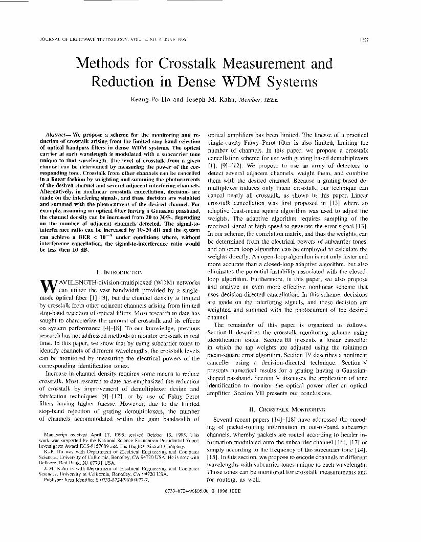
Fig. 1 presents our crosstalk monitoring scheme. At each transmitter, the current modulating the laser includes on-off- keyed data at baseband, multiplexed with a high-frequency tone that identifies the channel. The frequency of the subcarrier tone must be higher than the spectral tail of the data signal; if necessary, the data can be pre-filtered to eliminate crosstalk from the data channel to the subcarrier tone. While the subcar- rier channel can carry a header or other control information, for simplicity, we consider the subcarrier channel to be an unmodulated tone. At the receiver, the crosstalk induced by other channels is monitored by measurement of the power of the corresponding identification tones. For example, as shown in the Fig. 1, the crosstalk suffered by the ith channel can be measured from the electrical power at tone frequencies
Including the high-frequency identification tone, the current f k l , . f L i 2 , ' ' . .
modulating the laser of the ith channel is given by
where Ik,ias is the bias current to bring the laser above the threshold, d;(f,) E (0 , l ) i s the data modulation, m and h are the data and subcarrier modulation indices, which are a&umed to be identical for all channels, obeying the constraint that rn + 2h, = I, wst = 27~ f i is the angular frequency of the ith identification tone, and 4i is the initial phase of the ith tone.
We assume that the laser output power is proportional to Im,i - I,,ias, and we ignore laser chirp, fiber dispersion. fiber and optical amplifier nonlinearity. Those effects can be reduced by using external modulation or a low-chirp laser, dispersion compensation or dispersion-shifted fibers, and limiting the maximum power of each channel, respectively. The optical electric field at the output of the demultiplexer of kth channel can be written as follows:
N
Ek = &{m ' d , ( t ) + h[ l + cos (W,? t
2=1
. e 3 ( W L t + 6 % ) k , Z + %(t)@ + r n k ( t ) @ > k = l , . . . . N
where N is the number of optical channels, wi
t 4z)1>'/2
(2)
is the optical angular frequency of the ith channel, 6, is the random phase of the ith channel, pk , i is the optical power of ith channel at the output of kth channel demultiplexer, and Cl;,z is a complex unit vector indicating the light polarization. To include the effect of amplified spontaneous emission (ASE) arising from optical amplifiers, n,k ( t ) and m k ( t ) are broadband, independent, iden- tically distributed Gaussian noise processes traveling in two orthogonal polarizations, identified by the complex unit vectors 5 and q, respectively. In (2) , we assume that the bandwidth of the demultiplexer is much larger than the bandwidth of each individual channel, so that the filtering effects of each channel can be repre sented by constant factors P k , i and group- delay dispersion can be ignored. For example, the bandwidth of currently available grating-based demultiplexers i s in the range of several 8, (corresponding to several tens of GHz at
JOURNAL OF LIGHTWAVE TECHNOLOGY, VOL. 14, NO. 6, JUNE 1996
Electrical Spectrum of i-th Channel
Fig. 1. Crosstalk monitoring scheme using a subcarrier identification tone multiplexed with each individual channel. The level of crosstalk at each wavelengh is determined from the power of the corresponding identifying tone in the amplified photocurrent. The electrical spectrum of the Ith channel is shown as an example. (Tx: laser transmitter, Rx: receivea).
1.55 pm, as compared with data bandwidths of several GHz, so that our assumption is satisfied.
The photocurrent of the kth channel photodetector is equal to p l E k I 2 where p is the photodetector responsivity. We assume that each channel has a unique wavelength, so that no crosstalk arises from channels at the same wavelength [7], [19]. Our crosstalk-monitoring method can also be used to measure crosstalk arising from different channels using exactly the same wavelength, as long as different subcarrier frequencies are used. For example, this would be useful in networks that rely upon finite optical loss to permit wavelength reuse. Because the channel separation is much larger than the channel bandwidth, after ignoring the extremely high frequency terns with angular frequencies equal to w; - w j , i # ,j, the photocurrent plus input-referred noise is
N
ik(t) = P - y P k , i { T r L . d i ( t ) + h[ l + cos (W,$,t + + i ) ] ) 2=1
( 3 )
where i . k ~ ~ ( t ) , i sho t ( t ) , and i t h ( t ) are the Gaussian noise generated by ASE noise (both signal-spontaneous and spontaneous-spontaneous beat noises), shot noise, and thermal noise, respectively. The signal of the kth WDM channel is p p k , k m . d k ( t ) . The crosstalk from ith channel to kth channel is p p k , i r n . d&), i # k. The crosstalk can be characterized by the ratio p k , i / p k , k , z # k. All subcarrier tones w . ~ ~ contribute to neither signal nor nojse after low-pass filtering at the receiver.
The electrical power of the ith identification tone in the photocurrent of the kth channel demultiplexer is equal to
+ i A S E ( t ) + ishot( t ) + i th ( t )
(4)
Comparing the electrical power at f L to that at f k , we define the crosstalk level in electrical power as

~
HO AND KAHN: CROSSTALK MEASUREMENT AND REDUCTION IN DENSE WDM SYSTEMS
The demultiplexer electrical crosstalk in decibels is 10 . log,, .(XTk,,) dB, while the optical ratio is 5 . log,, .(XTk,,) dB. The average electrical signal power of the kth WDM channel is ( 1 / 2 ) ( p p k , k r n ) ’ = (m/h)27rk,fk.
B. Modulation Index of Identification Tones
The crosstalk power of ith channel at the demultiplexer of kth channel can be measured as shown in (5 ) , as long as 7rk,ft is detectable above the noise. Although we are not concerneld here with crosstalk levels less than -30 dB (since they have little effect on system performance), a crosstalk monitoring technique that can monitor very small crosstalk levels is desirable. When j ~ k , ~ is small, from (4), we see that the identification tone modulation index h must be made sufficiently large for the tone to be detectable. Another factor affecting the tone detectability is the bandwidth of the tone- detection circuit. When the bandwidth is made sufficiently small, a tone can be detected no matter how weak it is.
The required bandwidth depends on how fast we want to detect a change of the crosstalk level. If we want to detect the change of crosstalk within a time rL, then the bandwidth of tone detection should satisfy Bt > 217,. The crosstalk level of most demultiplexers remains fixed for a long time, so that Bt can be as small as 1 kHz, or even smaller. For packet-switched all-optical networks, packets on a wavelength channel are usually transmitted continuously. In most cases, stuff packets or stuff bits may be inserted even if no packet or data is required to be sent. However, in the worst case, when just a single packet lasting for a duration of rp is sent, the tone- detection bandwidth must be larger then Bt > 217, to avoid the reduction of tone-detection sensitivity.
Assuming that the data occupies a bandwidth of B d , the signal-to-Gaussian-noise ratio of the kth data channel is
where CASE. [silot, and & are the power spectral densities arising from ASE noise, shot noise and thermal noise, respec- tively. The subscript “dg” stands for data channel and Gaussian noise. We assume that all of those noises are white, allowing us to express the SNR as (6). The carrier-to-noise ratio (CNR) of the ith identification tone in the kth channel is
(7)
The crosstalk from channels at other wavelengths does not affect the CNR because the subcarrier frequencies of different channels are different. Relating CNRk,, to SNRdg,k
If we want to detect a minimum crosstalk level XT,,, (ratio in electrical power) with a minimum CNR,,,, the minimum h /m is given by
(9)
I129
-50 -45 -40 -35 -30 -25 -20 Minimum Detectable Crosstalk Level
XTmI, (Electrical dB)
Fig 2 The minimum modulation-index ratio ( h/in)III,,I required to dchleve a minimum detectable crosstalk level XT,,,,,, for different vdlues of BC</L?~? with CNRL,,, = 10 dB and SNR,i, k = 18 6 dB
Assuming the crosstalk is small, so that noise plus crosstalk is approximately Gaussian, the bit-error rate (BER) can be calculated by BER = Q(m) where SNR is the overall average signal-to-noise ratio, and Q(z) = ( l / 2 ) rrfc ( .r /f i) is the Gaussian Q function. For BER = 10~9,SNR,,r, = 18.6 dB. Due to the effect of crosstalk, we require SNRdg,k > 18.6 dB for BER = lop9. For a pessimistic estimation of ( h / v ~ ) , , ~ , we can use SNRdg,k = 18.6 dB in (9). Fig. 2 shows (h/m),,, as a function of XT,,,, for several values of Bd/Bt. Depending on the system configuration, a wide range of values of Bd/Bt may arise. For example, if B d > 1 GHz, Bt may be as small as 1 kHz and Bd/Bt > lo6. Considering a typical case of XT,,, = -35 dB, (h/rrL)ml,rl is in the range of 0.02 to 0.6, depending on BdlBt.
111. CROSSTALK CANCELLATION USING LINEAR CANCELLER
We may cancel the crosstalk by using multiple receivers tuned to channels at different wavelengths. Fig. 3 shows a schematic diagram of a linear crosstalk canceller for grating- based systems. The photocurrent from several detected chan- nels are weighted and summed to cancel the crosstalk. How- ever, our method cannot cancel crosstalk from channels having the same wavelength [7], [19]. Based on measured crosstalk levels, the weights can be calculated by a microprocessor that controls the canceller. Each weight tap may be implemented by a multiplier in which one input is the weight given by a digital- to-analog converter. The same technique can be applied using a filter bank [20]. Because the grating spectral response is usually symmetrical with respect to the desired signal channel, we assume here that the number of taps is an odd number.
Assume that n, taps are used with a weighting vector of W = ( ~ 1 . . . . , w , _ ) ~ . In order to detect the kth channel, the received photocurrents of n, receivers k - (n, - 1) /2 to IC + (n, - l ) / 2 are used. The photocurrent vector is
S ( t ) = Cd(t) + ’ I L ( t ) (10)
where

1130 JOURNAL OF LIGHTWAVE TECHNOLOGY, VOL. 14, NO. 6, JUNE 1996
S”“I --+
h I,..., h, ,... ~ hN
Fig. 3. Linear cancellation of linear crosstalk induced by a planar grating, using a weighted sum of nccr - 1 interfering signals with the desired signal. The crosstalk from each interfering channel is monitored by measurement of the electrical power of the corresponding identification tone.
C is an riw x N matrix in which ci,g = pmpk-(n ,+l ) /2+i .J
can be determined by the crosstalk monitoring scheme described in the last section, d ( t ) = ( d l ( t ) : . . . . d . k ~ ( t ) ) ~ is the transmitted data of all N channels, and ,n(t) = (nl ( t ) , . . . , n,_ (t))’ is the input-refen-ed Gaussian noise of each receiver. The received photocurrents are weighted and summed to generate the overall system output S,,,(t) = W’S(t). There are several algorithms that can used to choose the weighting vector.
A. Homogeneous and Nonhomogeneous MSE Minimization
One way to choose the weighting vector is to minimize the mean-squared-error (MSE) of the output signal with respect to the original data. In a homogeneous solution, the goal is to find W for Sout(L) = W‘S(t) such that the MSE ( e 2 ) = ([Soilt(t) - d k ( t ) ] ’ ) is minimized. This MSE is given by
For a given choice of weighting vector, we can now calculate the SNR. The overall Gaussian noise variance of the system is W T W o i , the overall average signal power is (1/2)(WTCek)’. the total variance of the crosstalk signal is (1/4)WTC(I - e k e l ) C T W . Therefore, the overall SNR is
The signal-to-crosstalk-interference ratio (SCIR) is 2( W7Cek)* /( W T C ( I - ekeT)CTW) .
B. Signal-to-Noise Ratio Maximization
Another way to choose the weighting vector W is to maximize the overall SNR in (15). The optimization proceeds by fixing (constraining) the numerator and minimizing the denominator of (15). Using a Lagrange multiplier, the solution is [22, pp. 4884931
WosNR = XRL’Cei (16)
where Rt = o$I+ ( C ( I - ekeT)CT)/4, X is a constant multi- plier given by XP1 = f-leTCTR,lCe; where WTCei = f is given by constraining the numerator of (15).
The weighting vector solution, given by (16) is identical to (14) within a scale factor [22, p. 4991. One can show that T,I,TXH ~ - clR,’Ce;, where c l 1 = 1/4 + eZCTRTICek . Therefore, M72sR = (X/cl)W?”, i.e., the two weighting vectors are identical within a scale factor, so that identical BER’ s are provided. Therefore, to save hardware cost, the weight for the desired signal can be set to unity (w(nw+l) /2 ---i 1). and the other weights can be scaled correspondingly, i.e.,
where R r l d is an N x N matrix that has 112 on the diagonal and 1/4 elsewhere, Rd, is a vector that has 112 in the kth Position and 1/4 elsewhere, I is an N X fl- identity matrix, and 0: = (CASE + + <th )Bd is the Variance of total Gaussian noise. We assume that all channels experience the
weighting vector is 121, p. 4081
C. Bit-Error-Rate Minimization
The ~~~~~i~~ approximation overestimates the BER for large crosstalk levels, F~~ a weighting vector of W, we define the crosstalk vector x = ((cl,. . . , ZW)’ as
same amount of Gaussian noise. The solution of the optimal x = CTW. (17)
The output signal can be expressed as W,” = (CRddC’ + a;I)-’CRd, (12)
obtained by setting Vw(e2) = 0. Because the matrix C is measured accurately by the crosstalk monitoring scheme, the weights can be calculated deterministically.
Detection of the desired signal &(t) can be improved if a constant is added to the sum, i.e., S,,,(t) = W O + W T S ( t ) . such that the MSE is minimized. In this nonhomogeneous case, the solution for the optimal weighting vector is [21, p. 4101:
S,,,(t) = z k d k ( t ) + c z . i d 7 ( % ) +,rio(t) (18) i f k
where the first term represents the desired signal, the sum- mation represents crosstalk from other channels, and no(i) is Gaussian noise with a variance of m: = WT Wa:. As the crosstalk consists of N - 1 channels d ; ( t ) that can send either “0” or “ l” , there are a total of Z N P 1 alternative combinations. Those alternatives can be represented by integers from 0 to
Cek, 2
22v-1- 1, the binary representation of these integers repre- senting whether a given channel transmits “0” or “1”. For the Zth crosstalk alternative, if 1; = 1, the ith channel transmits an “l”, and if Z i = 0, the ith channel transmits a “0”. The
W y = -(CC’/4 + aL1)-1 (13)
and
W O = ; (14) integer 1 is given by
1 = l k - 1 N
1 = E J - 1 + 1,i2’i-2.
i=l i=k+l where e ; is a unit vector that has unity at the ith position and zeros elsewhere.

HO AND KAHN: CROSSTALK MEASUREMENT AND REDUCTION IN DENSE WDM SYSTEMS 1131
Alternatively, the “bits” l i , i # k , can be determined from the binary representation of 1. The overall BER is
-1 2N-1
BER=- 1 {Q(-) 1=0
2 N
where D is the decision level, 11 = x k is the photocurrent when “1” is transmitted, and Z T , ~ = C ; j k Liz; is the total crosstalk amplitude for the lth crosstalk alternative. Typically, the decision level D is set to the mean signal-plus-crosstalk amplitude, or D = Er==, xi: D is also the mean of Sout(t).
In principle, using numerical methods, we can vary the weighting, vector W to minimize the BER given by (19). We refer to the weighting vector that yields minimum BER as However, for large number of crosstalk channels, the BER 1(19) is difficult to evaluate directly. Furthermore, as the numbler of weight taps increases, the optimization of tap weights becomes extremely difficult. Fortunately, as shown below, the choice of tap weights WosNR yields a BER that is indistinguishable from that obtained using WoBER.
D. Algorithm and Implementation Complexity In Section 11, we discussed the bandwidth required of the
tone-detection circuitry to determine the crosstalk matrix C. In this section, we discuss the complexity required to compute the tap weight vectors. We consider a situation that lends itself to kery efficient implementation, namely, when all N channels are to be detected at one location. Recall that for each channel, the crosstalk matrix C has rL, rows and N columns. To detect all channels, it might seem necessary to determine N x N entries from the crosstalk matrices for all N channels, i.e., the N unique rows appearing in the set of crosstalk matrices for the N channels. Often, however, many entries in these crosstalk matrices are very small, because there is little crosstalk between channels that are well-separated in wavelength. Assume that in each row of a crosstalk matrix C, there are only N c significant entries, i.e., each channel receives significant crosstalk from only N c - 1 other channels. It is obvious that n, 5 nc 5 N . It is only necessary to determine N c x N entries from the crosstalk matrices for the N channels in order to cancel crosstalk in all N channels.
In practice, the algorithm used to determine the weight vectors W should be simple enough to implement in a mi- croprocessor. While the BER-minimization algorithm yields the best performance in theory, this algorithm may be too complex to implement in real time. The MSE-minimization and SNR-maximization algorithms have very nearly the same complexity. We will discuss the complexity of implementing the SNR-maximization algorithm. For a N-channel system using 71, tap weights, after some arithmetic, we find that approximately ( N c + 2)n, N floating-point operations are needed to find the matrices Rt for all N channels. We note that the matrices Rt of the kth and ( k + l) th channels typically have many identical entries, which reduces the number of operations required. Assuming that we do not exploit this dependence
++p$+ Planar Grating
Monitor Adjustment Input
h ,,..., k ,“.., hN
Fig. 4. Nonlinear cancellation of linear crosstalk induced by a planar grating, using weighted sum of nu. - 1 detected interfering signals with the desired signal. A decision is made on each interfering signal before the weighted sum is formed.
of the entries in the various matrices R,, it takes about n$ operations to find the inverses R t l for all N channels, and another n, (n, + 1) operations to find the weight vectors. Considering a numerical example, if N = 40, n, = 5 , and NC = 11, it will require about 9000 operations to find the weight vectors of all 40 channels, or about 225 operations per channel. If we would like to update all weights within 1 ms, a 10 MIPS microprocessor is required. Some digital signal processing (DSP) microprocessors can perform much faster than 10 MIPS.’ If faster weight updates are needed or there are many more channels, multiple microprocessors may be required.
IV. CROSSTALK CANCELLATION USING NONLINEAR CANCELLER
As an alternative to linear crosstalk cancellation, we can first make decisions on the interfering signals before forming a weighted sum of n7” - 1 adjacent channels. This scheme is shown in Fig. 4. Unlike the linear canceller of Fig. 3, at low BER, the nonlinear canceller of Fig. 4 can cancel the crosstalk without enhancing the Gaussian noise. However, at high BER, there may be decision errors in the n, - 1 adjacent channels, leading to incorrect cancellation of crosstalk. Therefore, we would expect the nonlinear canceller to perform better then the linear canceller at low crosstalk levels, but to perform worse at high crosstalk levels. The nonlinear canceller is similar to the decision-feedback equalizer used in digital communication systems [23], but our technique is “decision-directed,’’ since decisions are not fed back.
In implementing nonlinear crosstalk cancellation, the level of crosstalk can be determined using the crosstalk monitoring scheme described in Section 11. In Fig. 4, the photocurrent signal at the kth port is
Assuming that all decisions on the interfering signals are correct, it is obvious that the tap weights should be chosen to completely cancel all crosstalk from the n, - 1 adjacent channels, i.e.,
wi - C k , k - ( n , + l ) / 2 + i / C k , k 1 i = 11‘.‘1nw - 1. We make this choice in all that follows.
The TMS320C3x and TMS320C4x floating-point DSP microprocessor from Texas Instruments have maximum speeds of 60 MIPS.

1 I32 JOURNAL OF LIGHTWAVE TECHNOLOGY, VOL 14, NO. 6, JUNE 1996
The BER performance of the nonlinear canceller is difficult to analyze. To simplify the analysis, we will treat the crosstalk from each of the n, - 1 detected adjacent channels as a binary random variable, but will treat the crosstalk from the remaining channels as Gaussian noise. Since this Gaussian-noise approx- imation slightly overestimates the BER, it underestimates the improvement using nonlinear canceller. Under this simplifying assumption, the photocurrent (20) can be rewritten as
nu-1
i k ( t ) s k d k ( t ) f 5; d,* ( t ) + nT(t) (21) i=l
where s k = C k , k is the signal amplitude of the kth channel,
x =(21r...,2n,--1) - - ( c k , k [ n w - l ) / ‘ 2 , . ‘ ’ > c k , k - - l % C k , k + l , ’ ‘ .
C k , k + [ n w - l ) / ’ 2 L
- - (dk,k-(n,-1)/2;“.1dk,k-l,dk.k+1~”.;
d k , k + ( n , - 1 ) / 2 )
represent the crosstalk level and input data of the n, - 1 adjacent channels, respectively, and n ~ ( t ) ~ which represents crosstalk from the other adjacent channels plus the receiver noise, is assumed to be Gaussian with variance of
k - (nul + 1 ) / 2 oT 2 = o:, + (1/4) Ci,i + (1/4) 2 Cz,i.
i=l i = k + ( n , +1) /2
Let us assume that the n, - 1 detected adjacent channels have BER’s of pb , , i = 1,. . . , n, - 1. Those BER’s can be evaluated using (19). There are three possible alternatives for each of these adjacent channels: no deci sion error, a decision error from “0’ to “1,” and a decision error from “1” to “0.” There are a total of 3nw-1 possible combinations, so it is difficult to evaluate the BER for all of them. Therefore, we will consider the worst case only. When the desired channel transmits a bit of “0” and all adjacent channels transmit “I,” if the receiver makes erroneous decisions of “0” on all of the adjacent channels, the crosstalk of the summed output will not be cancelled, and this constitutes one of the worst-case events. Similarly, another worst-case event is when the desired channel transmits a bit of “1,” all adjacent channels transmit bits of “O”, and the receiver makes decisions of “1” on all of those channels. It can be shown that both worst cases have same BER.
For the worst case, using a decision threshold of D = s k / 2 : the BER is upper-bounded by
where nu-1
P(1) = (1- ,=I
is the probability that the Zth alternative, in which 1, is the ith bit in the binary representation of I , such that the ith channel
is in error if I , = 1 and not in error if I , = O,xmax,l is the maximum crosstalk in the 2th alternative and
n... -1
i=l
V. NUMERICAL RESULTS
In the following numerical results, we consider a 40-channel dense WDM system. We assume that all channels arrive at all network nodes with the same optical power, and that all channels are subject to the same amount of loss and amplification, so that the ASE is identical for all channels. For the packet-switching case, we will assume that all channels are transmitting packets. This is the worst case because it has the largest amount of ASE and the largest amount of crosstalk interference. We consider a grating having a Gaussian passband shape [6] , [13]. The minimum crosstalk of the grating is -30 dB in terms of optical power, i.e., -60 dB in terms of electrical power. In other words, the spectral response of an output port with center frequency 00 and half-width-half- maximum (HWHM) bandwidth Ail is
T ( v ) = rriax 1 exp { - log 2( (,U - U ~ ) / A ~ ) ~ } , l o r 3 1 . (23)
The power penalty is calculated as
6,(dB) = 10 . log (SNR.d,,k/SNR,;,) (24)
where SNR,i, = 18.6 dB is the minimum SNR to achieve BER = lo-’ without crosstalk, and SNRdg,k is signal-to- Gaussian-noise ratio required to achieve BER = lo-’ in the presence of crosstalk arising from a specific channel spacing. The optical power penalty (in decibels) of the input optical signal is equal to 6, if the system is dominated by signal- spontaneous beat noise, because then SNRdg,k is proportional to the input optical power. The optical power penalty of input optical signal is equal to 6 4 2 if the system is dominated by thermal noise or spontaneous-spontaneous beat noise, because then SNRdg,k is proportional to the square of input optical power.
Fig. 5(a) presents the power penalties for the three-tap linear and nonlinear cancellers, while Fig. 5(b) presents penalties for the three-, five-, and nine-tap linear cancellers. The channel spacings that yield 1 and 3 dB penalties with various schemes are shown in Table I.
First, we compare the performance achieved using three- tap linear cancellers with different choice of the tap weights W. As stated in Section 111-C, the optimum choice is WfER, which is determined by numerical optimization to minimize the exact BER given by (19). To make this procedure tractable, in evaluation of (19), we have approximated all crosstalk terms having crosstalk levels below 5 x lop3 as Gaussian noise. We have also used (16) to find WoSNR; and evaluating the resulting BER using (19), we have found that WosNR yields the same BER as i.e., the solution WosNR is very nearly optimal. We recall that the choice of W:” yields the same performance as WosNR (see Section 1II.B). As shown in Fig. 5(a), the choice of weights W,” yields a power penalty that is just slightly larger than WosNR (or W,””).

HO AND KAHN: CROSSTALK MEASUREMENT AND REDUCTION IN DENSE WDM SYSTEMS
Gaussian approximation
1133
1 2.057 1.X94
3 1.598 1.417
5 1.547 1.309
9 1.542 1.293
10
8 5- E - E 16
a 2 4 ' No Crosstalk 3 a
0 C Q
0
2
ID 1 1.5 2 2.5
Channel Spacing / HWHM Bandwidth
(a) Nonlinear canceller
1 I3
13 h m
- 2 (6
a
U v
(II C Q
2 4
a :2
13 1 1.5 2 2.5 3
Channel Spacing / HWHM Bandwidth
(b)
Fig. 5. Power penalty as a function of channel spacing for a 40-channel WDM system using a demultiplexer having a Gaussian-shaped passband and a minimum optical crosstalk of -30 dB. (a) Three-tap linear and nonlinear cancellers. The linear equalizer achieves the same performance using weights ~7,"" and H,r?KR , and nearly the same performance using W,". (b) Three-, five- and nine-tap linear equalizers, using weights W2NR. With nine taps, the performance predicted by the Gaussian approximation is virtually the same as that calculated using the exact BER formula.
See text 3,5,7,9 1.504 1.380
When a three-tap linear canceller with the weights WzNR (or W:") is employed, for a 1 dB tolerable power penalty, the exact &ER formula (19) indicates that the channel spacing can be decreased from 1.953A~ to 1.543Av, corresponding to a 23?6 increase of channel density. Using the Gaussian approximation to evaluate the BER indicates that for a 1 dB tolerable power penalty, the channel density can be increased by 29%. If the tolerable power penalty is increased to 3 dB, the exact and Gaussian BER expressions indicate that the channel density can be increased by 19 and 34%, respectively.
When a three-tap nonlinear canceller is employed, for 1 and 3 dB permissible power penalties, increases in channel density of 30 and 18% can be obtained. Thus, as expected, the nonlinear canceller per forms better than its linear counterpart when crosstalk is weak, but worse when the crosstalk is strong. This is evident in Fig. 5(a) where it can be seen that the nonlinear canceller is superior for channel spacings smaller than about 1.4Au. When only a very small crosstalk penalty is
TABLE 1 CHANNEL SPACING YIELDING 1 AND 3 dB POWER PENALIl lM IN A 40 CHANNEL
WDM SYSTEM. THE GRATING DEMULTIPLEXER HAS A HALF-WIDTH AT HALF-MAXIMUM BANDWIDTH aU AND A MINIMUM OPTICAL CROSSTALK Ob -30 dB. WHEN ONLY ONE TAP IS USED, THERE IS No CROSSTALK CANCELLATION
Scheme I Eval;$;of 1 ;;;;; 1 C h ~ e l s p ~ ' A v f o r : 1 I-dB Penally 3-dB Penalty
Linear cy$per using WO
1 I 1.953 1 1.629
1.543 1.296
permissible, the nonlinear canceller permits a channel spacing of about 1.6Av. while the linear canceller requires a channel spacing of about 2.lAv. In most cases, the tolerable crosstalk penalty is small, and the nonlinear canceller is more effective than the linear canceller.
We now compare the performance achieved with linear cancellers having three, five, and nine taps. Numerical results show that as number of weights is increased beyond three, the difference in power penalties obtained using W," and WzNR (or W,"") becomes even smaller. With the choice of WoSNR, the exact BER expression (19) indicates that for 1 dB tolerable penalties, the three-, five-, and nine-tap linear cancellers yield increases in channel density of 23, 26, and 27%, respectively. For 3 dB tolerable penalties, the corresponding increases are 19, 25, and 26%, respectively. Thus, with the linear canceller, the use of five taps yields a significant improvement over three taps, but little marginal benefit is obtained by using more than five taps. For the case of the nonlinear canceller, our numerical results indicate that there is no significant improvement obtained by increasing the number of taps beyond three.
As mentioned above, typically, the Gaussian approximation Overestimates the BER for binary crosstalk, because it approx- imates the bounded binomial distribution with an unbounded Gaussian distribution. After crosstalk cancellation, the remain- ing crosstalk is very small, improving the accuracy of Gaussian approximation. In Fig. 5(a), we see that with three taps, the Gaussian approximation substantially overestimates the improvement achieved using crosstalk cancellation. However, in Fig. 5(b) we see that as the number of taps increases, the accuracy of Gaussian approximation improves. For example, for nine taps, there is very little difference between the BER's obtained using the Gaussian approximation and the exact formula (1 9).
Fig. 6 presents the SCIR versus channel spacing obtained using linear cancellers of one, three, five and nine taps, with tap weights W2NR. under conditions where the system power penalties are the same as those in Fig. 5(b). Using crosstalk cancellation, when the channel spacing exceeds ap- proximately 2 A u , crosstalk from other channels is almost

1134
50
JOURNAL OF LIGHTWAVE TECHNOLOGY, VOL. 14, NO. 6, JUNE 1996
40
Q 30 v
IT g 20
10
- 1 1.5 2 2.5 3
Channel Spacing / HWHM Bandwidth
Fig. 6. Signal-to-crosstalk-interference ratio (SCIR) as a function of channel spacing using tap weights WoSNR, under conditions such that the system power penalties are those shown in Fig. 5(b).
completely cancelled. However, without crosstalk cancellation, when the channel spacing becomes smaller than about 3Av. the crosstalk is dominated by several adjacent channels, and utilization of a canceller having just a few weights can reduce the impact of these dominant interferers, dramatically increasing the SCIR. A three-tap linear canceller can increase the SCIR by more than 20 dB, allowing a BER < lo-’ to be achieved even when, in the absence of crosstalk cancellation, the SCIR would be only 10 dB. The nine-tap linear canceller can improve the SCIR by nearly 25 dB, allowing BER < lo-’ to be obtained when the SCIR would otherwise be only 6 dB. Additional numerical results indicate that there is no significant difference between the SCIR obtained using W,“ and W:UR. We note that Fig. 6 does not show the SCIR of the nonlinear canceller because of the difficulty in defining the SCIR for a nonlinear canceller when decision errors are made in the estimation of crosstalk signals.
VI. OTHER APPLICATIONS OF IDENTIFICATION TONES
In addition to crosstalk monitoring, subcarrier identification tones have a wide range of potential applications in the future all-optical networks. Some well-known applications are for self-routing with and without header encoding [ 141-[ 181 and for contention recovery in all-optical networks [24]. Those applications have been discussed in the literature and will not be discussed further in this paper.
Another application of identification tones is for network management in all-optical networks with optical amplifiers. Optical amplifiers do not have a flat gain spectrum and have potential problems with gain saturation. Although there exist methods to equalize the gain spectrum and place the amplifiers so that all channels are received with approximately equal powers [25], such techniques require monitoring of the received power in each WDM channel, but no simple means has been proposed to perform this monitoring without demultiplexing to individual wavelengths. As shown in Fig. 7, the use of identification tones can be used to enable this monitoring to be performed without optical demultiplexing. A portion of the optical power at the amplifier output is detected using a high-speed photodetector, and the same scheme as
Amplifier
Eiectrlcal Spectrum______----’ of All NChannels
Frequency
Fig 7 Use of wavelength-identification subcarrier tones for monitoring power of WDM channels at output of optical amplifier A fraction of the power is split off and detected The electrical power of each identification tone indicates the optical power of the corresponding WDM channel
in Fig. 1 can be used to monitor the tone powers. The proper choice of modulation indices and splitting ratios can be analyzed using the method used in Section 11-B. We note that in the present instance, the ASE noise bandwidth and total optical power are approximately N times larger than the corresponding quantities in Section 11-B.
VII. CONCLUSION
We propose a scheme for the monitoring and cancellation of crosstalk arising from limited stop-band rejection of optical bandpass filters or gratings in dense WDM systems. The optical carrier at each wavelength is modulated with baseband on-off-keyed data, and also with a high-frequency, out-of-band subcarrier tone unique to that wavelength. At the receiver, the crosstalk from a given wavelength can be determined from measurement of the electrical power of the corresponding tone. We have determined the minimum ratio of the modulation index of the identification tone to the modulation index of digital baseband signal that is required to measure a given crosstalk level.
The crosstalk from other adjacent channels can be cancelled by using multiple receivers to detect different channels, and by forming a weighted sum of the detected signals. This summation may be made linearly or nonlinearly; in the latter case, decisions are made on the detected interfering signals before they are summed with the desired signal. We have described algorithms for determining the tap weights based on measured crosstalk levels. When a linear canceller is used with tap weights that minimize the MSE, maximize the overall SNR or minimize the BER, or when a nonlinear canceller is used, assuming a Gaussian-shaped demultiplexer passband, the channel density can be increased from 20 to 30%, depending on the tolerable crosstalk-induced penalty and the number of tap weights employed. The system can achieve a BER of even under conditions when, without crosstalk cancellation, the SCIR would be smaller than 10 dB.
REFERENCES
[ I ] S . B. Alexander et al., “A precompetitive consortium on wide-band all-optical networks,” J. Lightwave Technol., vol. 11, pp. 714-735, 1994.
[2] C. A. Brackett et al., “A scalable multiwavelength multihop optical network A proposal for research on all-optical networks,” J. Lightwave Technol., vol. 11, pp. 736-753, 1994.

HO AND KAHN: CROSSTALK MEASUREMENT AND REDUCTION IN DENSE WDM SYSTEMS 1135
P. E. Green, Jr. et al., “All-optical packet-switched metropolitan-area network proposal,” J. Lightwave Technol., vol. 11, pp. 754-763, 1994. A. M. Hill and D. B. Payne, “Linear crosstalk in wavelength-division- multiplexed optical-fiber transmission systems,” J. Lightwave Technol., vol. LT-3, pp. 643-651, 1985. P. A. Humblet and W. M. Hamdy, “Crosstalk analysis and filter optimrization of single- and double-cavity Fabry-Perot filters,” IEEE J. Select. Areas Commun., vol. 8 , pp. 1095-1 107, 1990. P. A. Rosher and A. R. Hunwicks, “The analysis of crosstalk in mul- tichannel wavelength division multiplexed optical transmission systems and its impact on multiplexer,” IEEE J. Select Areas Commun., vol. 8,
C. S. Li, C. M. Olsen, and D. G. Messerschmitt, “Analysis of crosstalk penally in dense optical chip interconnects using single-mode wave- guide..” J. Lightwave Technol., vol. 9, pp. 1693-1701, 1991. P. J. Legg, D. K. Hunter, 1. Andonovic, and P. E. Barnsley, “Inter- channel crosstalk phenomena in optical time division multiplexed switching networks,” IEEE Photon. Technol. Lett., vol. 6, pp. 661-663, 1994. P. A. Kirkby, “Multichannel grating demultiplexer receivers for high density wavelength systems,’’ J. Lightwave Technol., vol. 8, pp. 204-21 1, 1990. J. B. I). Soole, A. Scherer, H. P. LeBlanc, N. C. Andreadakis, R. Bhat, and Wl. A. Koza, “Monolithic InP/In-GaAsP/InP grating spectrometer for the 1.48-1.56 p m wavelength range,” Appl. Phys. Lett., vol. 58, pp.
C. Dragone, C. A. Edwards, and R. C. Kistler, “Integrated optics N X .iL‘ multiplexer on silicon,” IEEE Photon. Technol. Lett., vol. 3, pp. 813-815, 1991. H. Takahashi, Y. Hibino, Y. Ohmori, and M. Kawachi, “Polarization- insensitive arrayed-waveguide wavelength multiplexer with birefrin- gence compensating film,” IEEE Photon. Technol. Lett., vol. 5 , pp. 707-709, 1993. M. J. Minardi and M. A. Ingram, “Adaptive crosstalk cancellation in dense wavelength division multiplexed networks,” Electron. Lett., vol. 28, pp. 1621-1622, 1992. W. I. Way, D. A. Smith, J. J. Johnson, and H. Izadpanah, “A self-routing WDM high-capacity SONET ring network,” IEEE Photon. Technol. Lett., vol. 4, pp. 402405, 1992. M. W Maeda, A. E. Willner, J. R. Wullert, 11, J. Patel, and M. Allersrna, “Wavelength-division multiple-access network based on cen- tralized common-wavelength control,” IEEE Photon. Technol. Lett., vol. 4, pp. 83-85, 1993. P. Poggiolini and S. Benedetto, “Performance analysis of multiple sub- carrier encoding of packet headers in quasiall-optical WDM networks,” IEEE Photon. Technol. Lett., vol. 6, pp. 112-1 14, 1994. S. F. So, A. R. Bugos, V. Lanzisera, and R. Olshansky, “Demonstration of a multiple-access WDM network with subcarrier-multiplexed control channels,” IEEE Photon. Technol. Lett., vol. 6. pp. 461463, 1994. S. F. Su and R. Olshansky, “Performance of multiple access WDM networks with subcarrier multiplexed control channels,” J. Lightwave Techno!, vol. 11, pp. 1028-1033, 1993. E. I,. Coldstein, L. Eskildsen, A. F. Elrefaie, “Performance implica- tions of component crosstalk in transparent lightwave networks,” IEEE Photon. Technol. Lett., vol. 6, pp. 657-660, 1994. K.-P. Ho and J. M. Kahn, “Crosstalk cancellation in dense WDM systems, using filter-bank receiver,” in OFC ‘95, San Diego, CA, 1995, paper TuH7.
pp. 1108-1 114, 1990.
1949-1 95 1, 199 1.
[21] A. Papoulis, Probability, Random Variables, and Stochastic Processes. New York: McGraw-Hill, 1984, 2nd ed.
1221 P. E. Clarkson, Optimal and Adaptive Signal Processing. Boca Raton, FL: CRC Press, 1993.
1231 J. G. Proakis, Digital Communications. New York: McGraw-Hill, 1989, pp. 593-601.
1241 S. F. Su and R. Olshansky, “Use of subcarrier multiplexed acknowl- edgment tones for contention recovery in WDMA networks,” Electron.
[25) C .4 . Li, F. F.-K. Tong, C. 1. Georgious, and M. Chen, “Gain equal- ization in metropolitan and wide area optical networks using optical amplifiers,” in Proc. INFOCOM ‘94, Toronto, Ont., Canada, 1994, pp. 130-137.
Lett., vol. 29, pp. 1099-1100, 1993.
Keang-Po Ho received the B.S. degree from the National Taiwan University in 1991, and the M.S. and Ph.D. degrees in electrical engineering from the University of California at Berkeley in 1993 and 1995, respectively.
From 1992 to the Spring of 1995, he was a Research Assistant with the Department ofElectnca1 Engineering and Computer Sciences of the University of California at Berkeley, doing research in communication systems. During the Summer of 1994, he was with the IBM T. J. Watson Research Center working on all-optical networks. Currently, he is a Research Scientist at Bell- core, Red Bank, NJ. His current research interests are communication systems, communication theory, signal processing, image and video transmission, and wavelength division multiplexing systems.
Joseph M. Kahn (M’87) received the A.B. degree in physics in 1981, the M.A. degree in physics in 1983, and the Ph.D. degree in physics in 1986 from the University of California, Berkeley. His Ph.D. dissertation was entitled “Hydrogen-Related Acceptor Complexes in Germanium.”
He is an Associate Professor with the Department of Electrical Engineering and Computer Sciences at UC Berkeley. From 1987 to 1990, he was a Member of Technical Staff in the Lightwave Communica- tions Research Department of AT&T Bell Labora-
tories, Crawford Hill Laboratory, Holmdel, NJ, where he performed research on multigigabit-per-second coherent optical fiber transmission systems and related device and subsystem technologies. He demonstrated the first BPSK- homodyne optical fiber transmission system, and achieved world records for receiver sensitivity in multigigabit-per-second systems. He joined the faculty of University of California, Berkeley in 1990, where his research interests include optical fiber communication networks and transmission systems, local- area networks using free-space optical links, and optical interconnects in digital systems.
Dr. Kahn is a recipient of the National Science Foundation Presidential Young Investigator Award, and is a member of the IEEE Communications Society and the IEEE Lasers and Electro-optics Society. He is serving currently as a Technical Editor of IEEE Personal Communications Magazine.