RECOMMENDATION ITU-R S.2029 - Statistical methodology to assess
USAARL Report No. 2013-05
Methodology to Assess Field of View of Maxillofacial Protective Devices
By Jose E. Cap6-Aponte William McLean Josue Sosa Steve Martin
United States Army Aeromedical Research Laboratory
Sensory Research Division
November 2012
Approved for put>lic release; distribution unlimited.
Notice Qualified requesters Qualified requesters may obtain copies from the Defense Technical Information Center (DTIC), Cameron Station, Alexandria, Virginia 22314. Orders will be expedited if placed through the librarian or other person designated to request documents from DTIC. Change of address Organizations receiving reports from the U.S. Army Aeromedical Research Laboratory on automatic mailing lists should confirm correct address when corresponding about laboratory reports. Disposition Destroy this document when it is no longer needed. Do not return it to the originator. Disclaimer The views, opinions, and/or findings contained in this report are those of the author(s) and should not be construed as an official Department of the Army position, policy, or decision, unless so designated by other official documentation. Citation of trade names in this report does not constitute an official Department of the Army endorsement or approval of the use of such commercial items.

Standard Form 298 (Rev. 8/98)
REPORT DOCUMENTATION PAGE
Prescribed by ANSI Std. Z39.18
Form Approved OMB No. 0704-0188
The public reporting burden for this collection of information is estimated to average 1 hour per response, including the time for reviewing instructions, searching existing data sources, gathering and maintaining the data needed, and completing and reviewing the collection of information. Send comments regarding this burden estimate or any other aspect of this collection of information, including suggestions for reducing the burden, to Department of Defense, Washington Headquarters Services, Directorate for Information Operations and Reports (0704-0188), 1215 Jefferson Davis Highway, Suite 1204, Arlington, VA 22202-4302. Respondents should be aware that notwithstanding any other provision of law, no person shall be subject to any penalty for failing to comply with a collection of information if it does not display a currently valid OMB control number. PLEASE DO NOT RETURN YOUR FORM TO THE ABOVE ADDRESS. 1. REPORT DATE (DD-MM-YYYY) 2. REPORT TYPE 3. DATES COVERED (From - To)
4. TITLE AND SUBTITLE 5a. CONTRACT NUMBER
5b. GRANT NUMBER
5c. PROGRAM ELEMENT NUMBER
5d. PROJECT NUMBER
5e. TASK NUMBER
5f. WORK UNIT NUMBER
6. AUTHOR(S)
7. PERFORMING ORGANIZATION NAME(S) AND ADDRESS(ES) 8. PERFORMING ORGANIZATION REPORT NUMBER
9. SPONSORING/MONITORING AGENCY NAME(S) AND ADDRESS(ES) 10. SPONSOR/MONITOR'S ACRONYM(S)
11. SPONSOR/MONITOR'S REPORT NUMBER(S)
12. DISTRIBUTION/AVAILABILITY STATEMENT
13. SUPPLEMENTARY NOTES
14. ABSTRACT
15. SUBJECT TERMS
16. SECURITY CLASSIFICATION OF: a. REPORT b. ABSTRACT c. THIS PAGE
17. LIMITATION OF ABSTRACT
18. NUMBER OF PAGES
19a. NAME OF RESPONSIBLE PERSON
19b. TELEPHONE NUMBER (Include area code)
13-11-2012 Final
Methodology to Assess Field of View of Maxillofacial Protective Devices
Jose E. Capo-Aponte William McLean Josue Sosa Steve Martin
U.S. Army Aeromedical Research Laboratory P.O. Box 620577 Fort Rucker, AL 36362
USAARL 2013-05
U.S. Army Medical Research and Materiel Command 504 Scott Street Fort Detrick, MD 21702
USAMRMC
Approved for public release; distribution unlimited.
The frequency of maxillofacial battlefield injuries has steadily increased since World War II. While anecdotal reports from the Army aviation community credit maxillofacial shields (MFSs) with preventing aircrew injury during aviation mishaps, however no MFS exists to prevent combat-related maxillofacial injuries to ground Warfighters. MFSs that attach to combat helmets are being developed to provide facial protection to ground and mounted troops. An important consideration when developing maxillofacial protective devices is to achieve a balance between the protective coverage and the field of view (FOV) blockage induced by wearing MFSs. This study compared subjective and objective methodologies to measure the FOV of proposed MFSs. This evaluation showed that the use of objective methodology yield similar results compared to the subjective FOV methodology. The use of the objective FOV methodology will expedite the test and evaluation of future MFSs and give more accurate results by eliminating the variability induced by differences in subject responses.
field of view, FOV, facial protection, maxillofacial shield, Advanced Combat Helmet, ACH, Combat Vehicle Crew Helmet, CVCH
UNCLAS UNCLAS UNCLAS SAR 20
Loraine St. Onge, PhD
334-255-6906
Reset

This page is intentionally left blank.

iii
Table of contents
Page
Background ..................................................................................................................................... 1
Methods........................................................................................................................................... 2
Subjective assessment ................................................................................................................. 2
Objective assessment .................................................................................................................. 4
Data analysis ............................................................................................................................... 7
Results ............................................................................................................................................. 7
Discussion ..................................................................................................................................... 15
Conclusion .................................................................................................................................... 15
References ..................................................................................................................................... 15
List of figures
1. HGU-56/P aircrew helmet with maxillofacial shield. ................................................................ 1
2. Subjective FOV test conditions. ................................................................................................ 2
3. The Goldmann (Haag-Streit) kinetic perimeter. ........................................................................ 3
4. Modified perimeter chin rest. ..................................................................................................... 3
5. Polar meridian coordinates for subjective FOV measurement. ................................................. 4
6. Objective FOV assessment set up. .............................................................................................. 5
7. Objective assessment of the lower FOV. ................................................................................... 6
8. Objective assessment of the upper FOV. ................................................................................... 6
9. Comparison FOV graphs of ACH/MFS measured by objective and subjective methodology. 14
10. Comparison FOV graphs of CVCH/MFS measured by objective and subjective
methodology. ................................................................................................................................ 14

iv
Table of contents (continued) List of tables
Page
1. Subjective FOV (polar degree) for ACH (unrestricted; helmet only). ...................................... 8
2. Subjective FOV (polar degree) for ACH/MFS. ......................................................................... 8
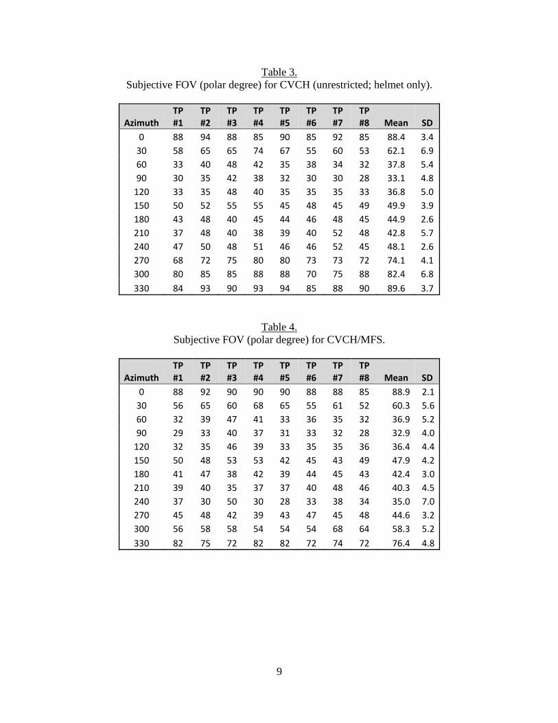
3. Subjective FOV (polar degree) for CVCH (unrestricted; helmet only). .................................... 9
4. Subjective FOV (polar degree) for CVCH/MFS. ...................................................................... 9
5. Converted subjective FOV (linear degree) for ACH (unrestricted; helmet only). .................. 10
6. Converted subjective FOV (linear degree) for ACH/MFS. ..................................................... 10
7. Converted subjective FOV (linear degree) for CVCH (unrestricted; helmet only). ................ 11
8. Converted subjective FOV (linear degree) for CVCH/MFS. .................................................. 11
9. Objective FOV (linear degree) for ACH/MFS ........................................................................ 12
10. Objective FOV (linear degree) for CVCH/MFS. ................................................................... 12
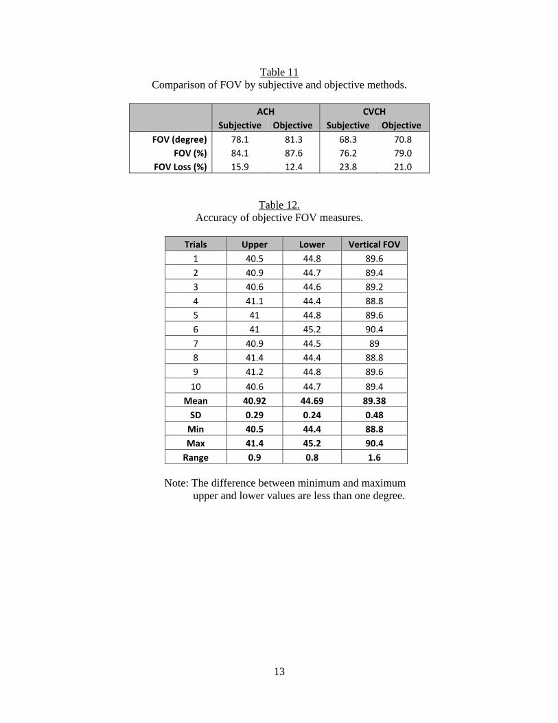
11. Comparison of FOV by subjective and objective methods. .................................................. 13
12. Accuracy of objective FOV measures. .................................................................................. 13

1
Background
Historically, the overall frequency of face and neck battlefield injuries has increased since World War II and the Korean War. During both of these conflicts, approximately 21percent of all injured U.S. service members suffered wounds to the head and neck (Beebe & DeBakey, 1952; Reister, 1973). In contrast, 26 percent of all battle wounds in Operation Iraqi Freedom (OIF) and Operation Enduring Freedom (OEF) involved craniomaxillofacial injuries (Lew, Walker, Wenke, Blackbourne, & Hale, G 2010). Penetrating soft-tissue injuries and bone fractures accounted for 58 percent and 27 percent of these craniomaxillofacial injuries, respectively. Improvement to body armor has increased Warfighters’ survivability of many previously fatal injuries. Anecdotal reports from the Army aviation community credit maxillofacial shields (MFSs; figure 1) with preventing aircrew injury during several aviation mishaps. An aircrew MFS protects the aircrew’s lower face from ballistic fragmentation and blunt impact as well as from rotor wash, flying debris, and windblast during helicopter operations. While anecdotal reports like these illustrate the protective nature of MFSs, no maxillofacial protection devices exist to prevent combat-related maxillofacial injuries to ground Warfighters.
Figure 1. HGU-56/P aircrew helmet with maxillofacial shield.
Maxillofacial protective devices that attach to the Advanced Combat Helmet (ACH) and the Combat Vehicle Crew Helmet (CVCH) are being developed to provide facial protection to ground and mounted troops, respectively. As the “honest broker” for the Warfighter, the U.S. Army Aeromedical Research Laboratory (USAARL) works with program managers to evaluate protective devices. With the increasing need to provide Warfighters with ballistic, blast, and blunt impact protection to the maxillofacial region, it is essential to understand potential operational problems associated with wearing maxillofacial protective devices. An important consideration when developing maxillofacial protective devices is to achieve a balance between the protective coverage and the field of view (FOV) blockage induced by wearing maxillofacial protective devices. While subjective assessment using a perimeter is commonly used to measure FOV, this methodology is very time consuming, requires the recruitment of test participants, and calls for potential modification to the perimeter to accommodate the bulky maxillofacial

2
protective devices. In addition, subjective FOV results are more variable due to differences in subject’s response time and device fitting. The present report compares subjective FOV measurements to a newly developed objective method that uses a head form and a laser pointer to determine the extent of FOV blockage induced by wearing maxillofacial protection devices attached to the ACH and CVCH.
Methods
Subjective assessment
Eight volunteer test participants were included in the subjective FOV evaluation. The Revision Baltskin Mandible Guard (Revision 2012), referred here as MFS (maxillofacial shield), was used for the evaluation. The FOV for each participant was measured under four test conditions using the: 1) ACH alone (unrestricted FOV); 2) ACH/MFS; 3) CVCH alone; and 4) CVCH/MFS (figure 2). The FOV was measured using the Goldmann (Haag-Streit) perimeter while the participant, who sat in a dark room, wore the helmet with and without the MFS (figure 3). The perimeter chin rest was modified to fit under the MFS allowing for vertical and front-back adjustment to properly align the participant inside the perimeter (figure 4, right image). The target stimulus was a high contrast, 1-millimenter (mm) diameter circle of white light that was projected on a hemisphere at a distance of 33 centimeters (cm) from the participant’s eye. The stimulus luminance was 50 foot-lamberts against a background luminance of 0.25 foot-lamberts. The investigator moved the illuminated target located at one of the 12 azimuths (30-degree intervals: 0, 30, 60, 90…330 degree) in relation to the participant’s right eye (figure 5). The illuminated target was moved at a steady rate (40 to 50 degrees) starting from the periphery towards the center. The target was always presented from a non-seeing to a seeing area and the participant signaled as soon as the target was seen. The target was brought in three times and the median reading was recorded for each azimuth. The FOV was tested randomly in all 12 pre-determined azimuths.
ACH (unrestricted) ACH/MFS CVCH (unrestricted) CVCH/MFS
Figure 2. Subjective FOV test conditions.
Since the MFSs are symmetrical around the eyes, the resulting fields of view (FOVs) are also expected to be symmetrical. Therefore, FOV measurements were conducted monocularly for the right eye only at 12 azimuths. While the upper and lateral FOVs are not expected to be affected

3
by wearing protective MFSs, the FOVs in these areas were measured to verify proper participant alignment throughout the testing. In addition, to ensure the participant’s position did not change during the testing, the participant wore rimless clear protective eyewear that had a 5-mm black dot located directly in front of the pupil of the right eye. The participant kept the black dot on the eyewear aligned with the fixation target located in the center of the perimeter hemisphere.
Figure 3. The Goldmann (Haag-Streit) kinetic perimeter. Perimeter demonstrated in a fully-lighted lab: test participant side of the perimeter (left image) and investigator side of the perimeter (right image).
Figure 4. Modified perimeter chin rest. The original chin rest (left image) was modified (right image) to fit under the MFS and to allow participant alignment.

4
Before initiating the testing, the investigator explained the evaluation to the participant, emphasizing the need to signal as soon as the illuminated target was seen and the importance of maintaining fixation as instructed. The participant was also instructed to blink normally any time during the testing. The untested eye (i.e., left eye) was occluded during the testing. The investigator ensured the proper fitting of the helmet and the helmet/MFS combination before the participant was assisted to position the chin onto the perimeter chin rest (figure 3, left image). The investigator adjusted the height of the perimeter table and/or the chin rest as appropriate to achieve proper participant alignment and comfort while in the testing position inside the perimeter hemisphere. After the completion of the FOV evaluation, the participant was allowed to rest for at least 5 minutes between test conditions to prevent fatigue. The entire series was repeated with all four test conditions.
Figure 5. Polar meridian coordinates for subjective FOV measurement. FOV was measures in 12 azimuths at 30-degree increments (0, 30, 60…, 300, and 330) from the perspective of the right eye.
Objective assessment
The objective FOV measurements were completed using a head form on a rotating table and an inclinometer with laser pointer (figure 6). A mount was made to attach the laser and the digital inclinometer, which could slide up and down approximately 1 meter. The inclinometer had degrees of tilt values in 0.1 units. To determine and assure that the pupil of the rigid head form was positioned at the center of rotation of the turn table, a long optical mounting rod was first screwed into the center of the rotating table. The laser on the vertical mount was activated, and the rotating table was moved laterally until the laser intercepted the center of the optical rod.

5
The optical rod was removed and the head form was then placed on the rotating table and moved laterally until the laser intercepted the pupil marked on the head form. The head form was then rotated about the yaw axis 90 degrees. The head form was then moved perpendicular to the laser beam until the laser beam aligned approximately 3-mm behind the apex of the cornea.
The different helmet/MFS combinations were mounted on the rigid head form, and the laser
was moved up and down, changing pitch, to align with the marked pupil on the head form. The laser height and pitch were adjusted until the laser intercepted the pupil of the head form and either the helmet structure for the upper FOV or the MFS for the lower FOV. Only the left eye measurements were taken from 50 degrees azimuth nasally to 90 degrees azimuth temporally. Figure 7 shows the lower FOV measurements alignment point, and figure 8 shows obtaining the upper FOV measurements.
Figure 6. Objective FOV assessment set up. The apparatus set up to measure angular objective FOV using a head form, rotating table, digital inclinometer, laser pointer, and a vertical optical mount.

6
Figure 7. Objective assessment of the lower FOV. Height of laser adjusted to intercept edge of the MFS and pupil of the eye to determine lower FOV angle.
Figure 8. Objective assessment of the upper FOV. Height of laser adjusted to intercept edge of the helmet and pupil of the eye to determine upper FOV angle.

7
Data analysis
The FOVs were measured with the Goldmann perimeter in polar meridian coordinate in 30-degree increments for all four test conditions. These FOV values, in polar meridian coordinates, were averaged for each meridian. Since the MFSs mainly affect the lower FOV, the average vertical FOV was calculated for each test condition. To calculate the average vertical FOV for each test condition, the average polar meridian coordinates were converted to linear degree measurements in x- and y- coordinates. The averaged y-values provided the linear degree of vertical FOV for each test condition. This conversion allowed the comparison of the subjective and objective FOV values. The FOV percent loss was determined by the equation: (1 – (average vertical MFS FOV/average vertical unhindered FOV))*100. The t-test was used to determine whether there was a significant difference between the mean FOV measured by the two methods. The FOV values for the right eye were used to create a symmetrical mirror image representing the left eye FOV. Binocular FOV graphs were plotted by combining the FOV data from the right eye and its mirror image for the left eye. These graphs portray the FOV from the observer’s perspective. The lines within the graph represent the mean FOV for each test condition and can be easily compared when overlaid on a single graph in lines of different colors or styles.
Results
Tables 1 through 4 list the FOV results of the subjective measurements in polar degrees as well as the mean FOV and standard deviation at each tested azimuth while the participant (indicated as TP in the tables) wore the ACH or CVCH with or without the MFS. Tables 5 through 8 show values converted to linear degree measurements in x- and y- coordinates. The averaged y-values provided the linear degree of vertical FOV for each test condition. Tables 9 and 10 list the FOV results of the objective measurement at each tested azimuth while wearing the ACH or CVCH with MFSs. As expected, wearing an MFS had no effect upon the superior and superior-lateral FOV. However, the MFSs reduced the FOV in 5 azimuths (i.e., 210, 240, 270, 300, and 330) in the inferior hemisphere, with both helmets. Compared to baseline values while wearing the ACH alone, wearing the MFS decreased the vertical FOV by 15.9, and 12.4 percent when measured with the subjective and objective methods, respectively (table 11). The MFS mean vertical FOV measured with the subjective and objective methods decreased by 23.8 and 21.0 percent, respectively when compare to the CVCH alone. A t-test showed that the difference between the means of the objective and subjective measurements were not statistically significant while wearing the ACH (p = 0.44) or CVCH (p = 0.55). Figures 9 and 10 show the individual FOV plots comparing the measurements obtained with the subjective and objective methods, respectively, for the each helmet/MFS combination. To determine the accuracy and stability of the laser method using repeated measures, the upper and lower FOVs were alternately measured at the zero azimuths for 10 measurements each using the CVCH/MFS combination (table 12).

8
Table 1. Subjective FOV (polar degree) for ACH (unrestricted; helmet only).
Azimuth TP #1
TP #2
TP #3
TP #4
TP #5
TP #6
TP #7
TP #8 Mean SD
0 90 88 90 90 92 92 90 85 89.6 2.3
30 65 65 50 70 70 68 58 65 63.9 6.8
60 55 55 45 45 48 48 40 45 47.6 5.2
90 45 45 40 42 42 42 37 40 41.6 2.7
120 50 50 45 45 48 48 40 45 46.4 3.3
150 55 55 40 52 53 52 55 50 51.5 5.0
180 40 40 40 46 46 46 48 44 43.8 3.3
210 45 40 38 42 42 43 52 45 43.4 4.2
240 60 52 50 56 50 58 53 62 55.1 4.6
270 63 70 75 60 59 65 69 63 65.5 5.5
300 78 80 85 88 88 88 75 83 83.1 5.0
330 90 95 90 92 92 92 88 92 91.4 2.1
Table 2. Subjective FOV (polar degree) for ACH/MFS.
Azimuth TP #1
TP #2
TP #3
TP #4
TP #5
TP #6
TP #7
TP #8 Mean SD
0 88 94 90 89 94 94 89 85 90.4 3.3
30 65 65 50 68 69 69 58 65 63.6 6.6
60 55 55 43 45 47 48 42 45 47.5 5.0
90 45 45 40 42 42 40 39 39 41.5 2. 5
120 50 50 43 45 48 48 40 45 46.1 3.5
150 52 55 40 52 53 52 56 48 51.0 5.0
180 45 41 40 46 45 45 45 43 43.8 2.2
210 45 40 35 38 38 38 45 43 40.3 3.7
240 50 38 62 35 35 35 45 62 45.3 11.7
270 36 43 33 30 38 30 31 37 34.8 4.6
300 55 65 68 75 77 76 72 74 70.3 7.4
330 79 95 90 90 90 90 86 88 88.5 4.6
9
Table 3. Subjective FOV (polar degree) for CVCH (unrestricted; helmet only).
Azimuth TP #1
TP #2
TP #3
TP #4
TP #5
TP #6
TP #7
TP #8 Mean SD
0 88 94 88 85 90 85 92 85 88.4 3.4
30 58 65 65 74 67 55 60 53 62.1 6.9
60 33 40 48 42 35 38 34 32 37.8 5.4
90 30 35 42 38 32 30 30 28 33.1 4.8
120 33 35 48 40 35 35 35 33 36.8 5.0
150 50 52 55 55 45 48 45 49 49.9 3.9
180 43 48 40 45 44 46 48 45 44.9 2.6
210 37 48 40 38 39 40 52 48 42.8 5.7
240 47 50 48 51 46 46 52 45 48.1 2.6
270 68 72 75 80 80 73 73 72 74.1 4.1
300 80 85 85 88 88 70 75 88 82.4 6.8
330 84 93 90 93 94 85 88 90 89.6 3.7
Table 4. Subjective FOV (polar degree) for CVCH/MFS.
Azimuth TP #1
TP #2
TP #3
TP #4
TP #5
TP #6
TP #7
TP #8 Mean SD
0 88 92 90 90 90 88 88 85 88.9 2.1
30 56 65 60 68 65 55 61 52 60.3 5.6
60 32 39 47 41 33 36 35 32 36.9 5.2
90 29 33 40 37 31 33 32 28 32.9 4.0
120 32 35 46 39 33 35 35 36 36.4 4.4
150 50 48 53 53 42 45 43 49 47.9 4.2
180 41 47 38 42 39 44 45 43 42.4 3.0
210 39 40 35 37 37 40 48 46 40.3 4.5
240 37 30 50 30 28 33 38 34 35.0 7.0
270 45 48 42 39 43 47 45 48 44.6 3.2
300 56 58 58 54 54 54 68 64 58.3 5.2
330 82 75 72 82 82 72 74 72 76.4 4.8

10
Table 5. Converted subjective FOV (linear degree) for ACH (unrestricted; helmet only).
Azimuth Upper FOV Lower FOV Vertical FOV
‐40 46.2 0.0 46.2
‐30 52.0 ‐30.1 82.1
‐20 53.8 ‐41.2 95.0
‐10 54.9 ‐47.6 102.5
0 54.1 ‐52.3 106.4
10 53.8 ‐55.4 109.2
20 54.9 ‐58.1 113.0
30 54.9 ‐59.4 114.3
40 52.9 ‐59.2 112.1
50 48.6 ‐55.1 103.7
60 43.2 ‐50.0 93.2
70 33.6 ‐42.9 76.5
80 22.6 ‐30.1 52.7
Mean Vertical FOV 92.8
Table 6. Converted subjective FOV (linear degree) for ACH/MFS.
Azimuth Upper FOV Lower FOV Vertical FOV
‐40 46.0 3.0 43.0
‐30 50.0 ‐18.1 68.1
‐20 55.5 ‐25.2 80.7
‐10 55.5 ‐21.0 76.5
0 54.0 ‐20.0 74.0
10 53.9 ‐29.3 83.2
20 53.9 ‐38. 8 92.7
30 55.1 ‐45.2 100.3
40 52.2 ‐48.8 101.0
50 48.5 ‐46.8 95.4
60 42.0 ‐41.2 83.2
70 34.3 ‐35.1 69.4
80 23.0 ‐25.0 48.0
Mean Vertical FOV 78.1

11
Table 7. Converted subjective FOV (linear degree) for CVCH (unrestricted; helmet only).
Azimuth Upper FOV Lower FOV Vertical FOV
‐40 34.9 ‐10.3 45.2
‐30 38.0 ‐32.7 70.7
‐20 38.9 ‐48.3 87.2
‐10 38.9 ‐60.0 98.9
0 38.9 ‐68.7 107.6
10 39.1 ‐70.9 110.0
20 38.6 ‐70.9 109.5
30 38.9 ‐68.6 107.5
40 38.7 ‐67.1 105.8
50 39.1 ‐62.4 101.4
60 35.1 ‐56.1 91.2
70 26.7 ‐48.9 75.7
80 16.8 ‐37.8 54.6
Mean Vertical FOV 89.6
Table 8. Converted subjective FOV (linear degree) for CVCH/MFS.
Azimuth Upper FOV Lower FOV Vertical FOV
50 45.6 0.0 45.6
40 49.7 ‐15.1 64.8
30 52.0 ‐14.4 66.4
20 54.8 ‐15.6 70.4
10 56.1 ‐23.3 79.4
0 54.0 ‐28.1 82.1
‐10 54.6 ‐42.5 97.1
‐20 55.7 ‐46.7 102.4
‐30 55.7 ‐45.0 100.7
‐40 50.7 ‐44.6 95.3
‐50 45.2 ‐42.7 87.9
‐60 44.0 ‐40.1 84.1
‐70 40.8 ‐35.5 76.3
‐80 38.3 ‐32.8 71.1
‐90 33.5 ‐26.7 60.2
Mean Vertical FOV 81.3

12
Table 9. Objective FOV (linear degree) for ACH/MFS.
Azimuth Upper FOV Lower FOV Vertical FOV
50 45.6 0.0 45.6
40 49.7 ‐15.1 64.8
30 52.0 ‐14.4 66.4
20 54.8 ‐15.6 70.4
10 56.1 ‐23.3 79.4
0 54.0 ‐28.1 82.1
‐10 54.6 ‐42.5 97.1
‐20 55.7 ‐46.7 102.4
‐30 55.7 ‐45.0 100.7
‐40 50.7 ‐44.6 95.3
‐50 45.2 ‐42.7 87.9
‐60 44.0 ‐40.1 84.1
‐70 40.8 ‐35.5 76.3
‐80 38.3 ‐32.8 71.1
‐90 33.5 ‐26.7 60.2
Mean Vertical FOV 81.3
Table 10. Objective FOV (linear degree) for CVCH/MFS.
Azimuth Upper FOV Lower FOV Vertical FOV
‐50 29.5 0.0 29.5
‐40 32.9 ‐15.3 48.2
‐30 36.1 ‐15.7 51.8
‐20 38.2 ‐15.9 54.1
‐10 40.1 ‐28.5 68.6
0 41.1 ‐42.0 83.1
10 42.2 ‐44.0 86.2
20 42.7 ‐43.5 86.2
30 42.4 ‐44.6 87.0
40 40.3 ‐43.3 83.6
50 39.0 ‐41.6 80.6
60 35.4 ‐40.1 75.5
70 32.6 ‐35.5 68.1
80 29.7 ‐32.5 62.2
90 25.7 ‐29.9 55.6
Mean Vertical FOV 70.8
13
Table 11 Comparison of FOV by subjective and objective methods.
ACH CVCH
Subjective Objective Subjective Objective
FOV (degree) 78.1 81.3 68.3 70.8
FOV (%) 84.1 87.6 76.2 79.0
FOV Loss (%) 15.9 12.4 23.8 21.0
Table 12. Accuracy of objective FOV measures.
Trials Upper Lower Vertical FOV
1 40.5 44.8 89.6
2 40.9 44.7 89.4
3 40.6 44.6 89.2
4 41.1 44.4 88.8
5 41 44.8 89.6
6 41 45.2 90.4
7 40.9 44.5 89
8 41.4 44.4 88.8
9 41.2 44.8 89.6
10 40.6 44.7 89.4
Mean 40.92 44.69 89.38
SD 0.29 0.24 0.48
Min 40.5 44.4 88.8
Max 41.4 45.2 90.4
Range 0.9 0.8 1.6
Note: The difference between minimum and maximum
upper and lower values are less than one degree.

14
Figure 9. Comparison FOV graphs of ACH/MFS measured by objective and subjective methodology.
Figure 10. Comparison FOV graphs of CVCH/MFS measured by objective and subjective methodology.

15
Discussion
This evaluation showed that the use of an objective methodology yields similar results compared to the subjective FOV methodology. Objective FOV assessment will expedite the test and evaluation of future MFSs and give move accurate results by eliminating the variability induced by differences in participant’s response time and device fitting. As would be expected, MFS reduced the user’s FOV, especially in the lower hemisphere. The more facial area protected, the less the FOV. It is therefore important to understand how proposed integrated helmet/maxillofacial protection systems can affect the Warfighter’s FOV, which in turn could negatively impact combat performance. Other test data (e.g., blunt impact, ballistics, back face deformation) should also be used in conjunction with FOV measurements to determine the combined head/face system(s) that will optimize protection without hindering the combat performance of ground and mounted Warfighters. In addition, decision makers must consider that these are static FOV measurements and that, in practice, the user will move the head as necessary to see what must be viewed. Therefore, the FOV restriction noted may be less troublesome in practice than the results may indicate. However, in many situations, head movement should or must be limited, meaning that FOV in an operational environment should be maximized to avoid extraneous head movement.
Conclusion
The objective FOV assessment using the laser pointer, digital inclinometer with a rigid head form on a rotating table will provide repeatable FOV measurements for comparison purposes among competing maxillofacial protective shields without the variability associated with human subjects.

16
References Beebe, G. and DeBakey, M. 1952. Location of hits and wounds. Battle Casualties, 165-205.
Springfield, IL: Charles C. Thomas. Lew, T. A., Walker, J. A., Wenke, J. C.,Blackbourne, L. H., and Hale, R. G. 2010.
Characterization of craniomaxillofacial battle injuries sustained by United States service members in the current conflicts of Iraq and Afghanistan. Journal of Oral and Maxillofacial Surgery. 68(1): 3-7.
Reister, F. 1973. Battle casualties and medical statistics: U.S. Army experience in the Korean
War. Washington, DC. The Surgeon General, Department of the Army. Revision Batlskin Mandible Guard Product Data. Last accessed 29 Aug 2012 from
http://www.revisionmilitary.com/store/batlskin-mandible-guard-kit-for-ach-helmet-small-medium-and-large-x-large.html.

Department of the Army U.S. Army Aei'Omeclical Research Laboratory
Fort Rucker, Alabama, 36362-0577 www.usaarl.army.mil
U.S. Arrny Medical Research ancl Materiel Command