METHODOLOGY OF 3D HYDRAULIC DESIGN OF A … · Hydraulic design of blade section of the pump and...
12
Engineering MECHANICS, Vol. 20, 2013, No. 2, p. 107–118 107 METHODOLOGY OF 3D HYDRAULIC DESIGN OF A IMPELLER OF AXIAL TURBO MACHINE Michal Varchola*, Tomaˇ s Bielik*, Peter Hlboˇ can* The paper deals with a hydraulic design of an axial propeller in function of pump and in function of turbine as well. A meridional cut of a turbo machine is proposed by classical method following guiding parameters. Experimental findings about an interaction between parameters of the turbo machine in pump and turbine mode are implemented in this procedure. Blade cuts are proposed following NACA airfoils with using of their aerodynamic characteristics, which are processed numerically. Also Voznesensky diagram, which is used to predict an influence of an airfoil in a blade grid was processed numerically as well. The result is a complete design with text-file output, which is directly capable to be used as an input for 3D environment (e.g. CATIA). Keywords : axial machine, turbine impeller, pump impeller, hydraulic solution 1. Introduction Hydraulic design of axial machine is characterized by a relatively complex procedure from design of meridional section to application of aerodynamic profiles into the blade cascade of axial impeller. Therefore numerical processing and graphical output to a 3D environment has a great importance because it leads to the operative hydraulic design of blade systems. The main subject of this paper is numerical processing and mechanism of the total 3D output process. Each turbomachine is fundamentally reversible. This means that it can work in the function of generator – pump as well as in the function of motor – turbine. The question of what are the parameters of the machine in the pump mode and in the turbine mode is also the subject of hydraulic design. In this paper, the same methodology is used for hydraulic design of the impeller of the pump and the turbine as well. Experimental results of pump mode operation are available for the comparison in Fig. 2. Each hydraulic design consists of two almost independent procedures. The first one is the design of the pump ’ ts meridional section including the impeller and the second one is the calculation of the blades’ shape on a cylindrical surface of the meridional section. 2. Hydraulic design of the meridional section of the pump and the turbine The first principle is the constant meridional velocity from entering the impeller to exit from it. We utilize guiding parameters such as K m , which implicitly contains optimizing elements obtained from the theoretical and experimental research. Basic dimensions of the meridional section are shown in Fig. 1. * prof. Ing. M. Varchola, CSc., Ing. T. Bielik, Ing. P. Hlboˇ can, Institute of Chemical and Hydraulic Machines and Equipment, Faculty of Mechanical Engineering, Slovak University of Technology in Bratislava
Transcript of METHODOLOGY OF 3D HYDRAULIC DESIGN OF A … · Hydraulic design of blade section of the pump and...

Engineering MECHANICS, Vol. 20, 2013, No. 2, p. 107–118 107
METHODOLOGY OF 3D HYDRAULIC DESIGNOF A IMPELLER OF AXIAL TURBO MACHINE
Michal Varchola*, Tomas Bielik*, Peter Hlbocan*
The paper deals with a hydraulic design of an axial propeller in function of pumpand in function of turbine as well. A meridional cut of a turbo machine is proposedby classical method following guiding parameters. Experimental findings about aninteraction between parameters of the turbo machine in pump and turbine modeare implemented in this procedure. Blade cuts are proposed following NACA airfoilswith using of their aerodynamic characteristics, which are processed numerically. AlsoVoznesensky diagram, which is used to predict an influence of an airfoil in a bladegrid was processed numerically as well. The result is a complete design with text-fileoutput, which is directly capable to be used as an input for 3D environment (e.g.CATIA).
Keywords : axial machine, turbine impeller, pump impeller, hydraulic solution
1. Introduction
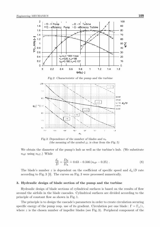
Hydraulic design of axial machine is characterized by a relatively complex procedure fromdesign of meridional section to application of aerodynamic profiles into the blade cascade ofaxial impeller. Therefore numerical processing and graphical output to a 3D environmenthas a great importance because it leads to the operative hydraulic design of blade systems.The main subject of this paper is numerical processing and mechanism of the total 3D outputprocess. Each turbomachine is fundamentally reversible. This means that it can work in thefunction of generator – pump as well as in the function of motor – turbine. The question ofwhat are the parameters of the machine in the pump mode and in the turbine mode is alsothe subject of hydraulic design. In this paper, the same methodology is used for hydraulicdesign of the impeller of the pump and the turbine as well. Experimental results of pumpmode operation are available for the comparison in Fig. 2.
Each hydraulic design consists of two almost independent procedures. The first one isthe design of the pump’ts meridional section including the impeller and the second one isthe calculation of the blades’ shape on a cylindrical surface of the meridional section.
2. Hydraulic design of the meridional section of the pump and the turbine
The first principle is the constant meridional velocity from entering the impeller to exitfrom it. We utilize guiding parameters such as Km, which implicitly contains optimizingelements obtained from the theoretical and experimental research. Basic dimensions of themeridional section are shown in Fig. 1.
* prof. Ing. M.Varchola, CSc., Ing. T. Bielik, Ing. P.Hlbocan, Institute of Chemical and Hydraulic Machinesand Equipment, Faculty of Mechanical Engineering, Slovak University of Technology in Bratislava

108 Varchola M. et al.: Methodology of 3D Hydraulic Design of a Impeller of Axial Turbo Machine
Fig.1: The main dimensions of the axial turbomachine
Hydraulic solution is based on Q, Y , n (we assume temperature of 20 ◦C) :
1. We calculate the specific speed
nb = n
√Q
Y 0.75, (1)
2. Guiding parameter :for the pump :
Km = 0.0688 + 0.733n1.1b , 0.33 < nb < 1 , (2)
for the turbine :KmT = 0.76nbT + 0.0206 . (3)
ThencmT = KmT
√2 g HT . (4)
3. Diameter of the pump’s impeller (Fig. 1)
D2 = DA =
√√√√√4π
1.04QKm
√2 Y(1)
1
1 −(DB
DA
)2 . (5)
Diameter of the turbine’s impeller
D2T = DA = KDT3
√QT
nT. (6)
Guiding parameter of the outer diameter :
KDT = 0.9781− 0.3336 ln(nbT) . (7)
Engineering MECHANICS 109
Fig.2: Characteristic of the pump and the turbine
Fig.3: Dependence of the number of blades and nb
(the meaning of the symbol ϕr is clear from the Fig. 5)
We obtain the diameter of the pump’s hub as well as the turbine’s hub. (We substitutenbP using nbT.) While
dn
D=DB
DA
.= 0.63 − 0.346 (nbP − 0.25) . (8)
The blade’s number z is dependent on the coefficient of specific speed and dn/D rateaccording to Fig. 3 [3]. The curves on Fig. 3 were processed numerically.
3. Hydraulic design of blade section of the pump and the turbine
Hydraulic design of blade sections of cylindrical surfaces is based on the results of flowaround the airfoils in the blade cascades. Cylindrical surfaces are divided according to theprinciple of constant flow as shown in Fig. 1.
The principle is to design the cascade’s parameters in order to create circulation securingspecific energy of the pump resp. use of its gradient. Circulation per one blade : Γ = Γz/z,where z is the chosen number of impeller blades (see Fig. 3). Peripheral component of the

110 Varchola M. et al.: Methodology of 3D Hydraulic Design of a Impeller of Axial Turbo Machine
mean relative velocity using the particular cylindrical section can be determined from therelation (Fig. 4).
wu∞ = u− cu2
2= u− Y
2πD nηh. (9)
Then we can define angle β∞ :β∞ = arctan
cmwu∞
. (10)
The angle of the cascade’s inclination :
βe = β∞ + δ .
In the first iteration we choose the angle βe = β∞, then we choose βe = β∞ + δ, where δ isthe chosen angle of the attack (Fig. 4).
Fig.4: Velocity triangles and the cascade of axial pump
Fig.5: View on the cylindrical blade sections
The central angle ϕr (Fig. 5) depends on specific speed, DB/DA ratio and blades’ num-ber z (Fig. 2). It can be calculated using numerically processed diagram (Fig. 3) with re-strictive condition :
ϕr = 9.4818n2b − 30.426nb + 94.502 . (11)
After the calculation of the central angle ϕr we can estimate the length of the profile’s chord :
l =ϕrD
2cosβe
(12)

Engineering MECHANICS 111
and relative pitch :t
l=πD
z l. (13)
Coefficient of cascade’s impact ξ can be defined using the equations describing the diagram(Fig. 7) according to the relative pitch t/l and the angle of the cascade’s inclination βe.In order to process the calculation fully automatically with minimum user’s input, it isnecessary to transform this diagram into the digital form (Fig. 7). It is the most importantchange which determines the ratio of lift on a single profile in the tunnel to lift on the sameprofile located in the cascade [1]. Then the mean geometric velocity is :
w∞ =√c2m + w2
u∞ . (14)
The angle of profile’s deflection :
β∗ =Γ
ξ w∞ l. (15)
Change of the angle of attack Δδ will be defined using the diagram (Fig. 8) with dependenceon the relative pitch t/l and the angle of profile’s deflection β∗. The diagram was numericallyprocessed as well. As a rule, the calculation can be more precise by changing the angle δ byΔδ. The angle of the cascade’s inclination :
βe = β∞ + δ + Δδ . (16)
Coefficient of cascade’s impact : ξ – will be defined according to Fig. 7 with dependence onthe relative pitch t/l and the angle of the cascade’s inclination βe. Single profile concludeslift factor (cz)1 and profile located in the cascade concludes lift factor (cz).
ξ =(cz)1(cz)
. (17)
Lift factor for single profile :
(cz)1 =2 Γl w∞
1.6ξ
. (18)
Then we control cz using NACA profile. The induced angle of attack :
δi = 57.3(cz)1π λ
. (19)
The angle of attack for the final span :
δλ = δi + Δδ .
Then we calculate the relative deflection (m/l)40% in the distance L∗ = 0.4 l (Fig. 6) [1] :
m
l=
sin2
(β∗
2
)
sinβ∗ − 120
tanβ∗
5. (20)
Furthermore, we have to choose :– the relative thickness of the profile,– the relative distance of the maximum deflection.

112 Varchola M. et al.: Methodology of 3D Hydraulic Design of a Impeller of Axial Turbo Machine
Fig.6: Centerline of the NACA profile compared toan equivalent circular arc of Voznesensky
Using calculated value m/l and chosen values t∗/l, L∗/l (which are chosen according tothe stress and material) we can estimate the required NACA profile.
If the value (cz) corresponds in tolerance 0–3% with the value (cz)1 calculated usinginput parameters, then we can finish the calculation. Usually, the agreement is not reachedfor the first time and it is necessary to repeat the calculation with different angle of attack δ.
By the calculation we can obtain geometric characteristics m/l, t∗/l, L∗/l. Based onthese characteristics and relations for the NACA profile [1], we define the complete blade’sprofile, which corresponds to the hydraulic design. Calculation is repeated for all five bladesections.
For the design of the entire blade’s surface it is necessary to include the position of eachblade section to match to the smallest torque (axis position normally resides in 40% of thelength of the profile).
Besides the correction of lift coefficients it is necessary to process a number of othercorrections as well. Particularly the following corrections :
a) A correction to a difference of an airfoil span in a wind tunnel and in an impeller. Whilethe profile wing, which was tested in a wind tunnel, has the finite span , blades in animpeller are restricted by a casing and by a hub of a pump, so they can be consideredas profile wings with an infinite span. It can be expressed also that a wing span aspectratio, which is given by a ratio , has a finite value in a case when the airfoil was testedin a wind tunnel but it has an infinite value in a case of profiled blades in an impeller.
b) A correction to different turbulence intensity in a wind tunnel and in an impeller. Thisequation is usually neglected because dimensions which are typical for turbomachinesguarantee generally highly turbulent flow.
Voznesensky goes out from induced velocities with an infinite count of vortex filamentslocated around airfoils in a blade cascade (they are replaced by arcs), which are flown aroundby velocity w∞. This velocity can be estimated according to a velocity triangle (Fig. 4). Itfollows the requirement that profiles in a blade cascade would be flown around optimally, itmeans they should be flown around with minimal losses and circulation caused by a bladecascade should correspondent to a given specific energy. It is necessary to replace a bladecascade which is represented by arcs by a blade cascade which has the same hydrodynamicproperties. In this case arcs of a blade cascade are replaced by a NACA airfoil.
We choose value of L∗ equal to 0.4 l for designed airfoils because a camber line of an airfoilNACA is sufficiently coextend with an arc of a theoretical blade cascade of Voznesensky

Engineering MECHANICS 113
Fig.7: Dependency of a coefficient of cascade’s impact ξ on relativepitch t/l and angle of a blade cascade inclination βe
Fig.8: Dependency of a difference of an angle of attack Δδ on relativepitch t/l and angle of an airfoil deflecton β∗ of a blade cascade βe
(Fig. 6) for this value. Besides that the length L∗ = 0.4 l is assumed as an optimal place fora pin of an impeller blade because of a favorable course of a torque due to hydrodynamicforces which force on a blade. A requirement on rigidity is not omitted because a maximalthickness of an airfoil t∗ is usually located in an area of a maximal arching of an airfoil.
This algorithm follows the issue with more complexity because it comprises into calcu-lation also a change of an angle of attack δ according to parameters of a blade cascade(according to a ratio t∗/l and an angle of arching of an airfoil β∗ (Fig.8)).
Within the design of axial turbomachines is a procedure which governs a hydraulic designof an impeller based on theory of ala nasi. The complexity of a solution is a reason whyonly planar blade cascades can be investigated; it means only blade cascades with infinitythin camber profile. It is important to insist also on the requirement of blade rigidity, whileimpellers with swiveling blades are usually thicker than impellers with rigid blades. By thisapproach a utilization of theoretical exploration of planar blade cascades with experimental

114 Varchola M. et al.: Methodology of 3D Hydraulic Design of a Impeller of Axial Turbo Machine
Fig.9: Main dimensions of NACA airfoil
Fig.10: NACA airfoil – determining of vertices
results is monitored. Experimental results were obtained by measurements in wind tunnels(hydro tunnels) on NACA airfoils.
Design of NACA profile consists of a specification of an airfoil camber line and a calcu-lation of a body of an airfoil follows. A camber line of an airfoil consists of two paraboliccurves which have a common tangent line which is parallel with a profile chord. A distancebetween a tangent line and a leading edge is equal to L∗. We have to know geometric cha-racteristics of a profile which was calculated during the design of an impeller to designatea shape of camber line. Then we can step up to calculation of NACA profile camber line ofthis algorithm.
a) It is necessary to choose coordinates from a leading edge of a profile where x = 0 to anend of the profile where x = 1 (Fig. 10).
b) After determining of necessary points with coordinates x we can begin with assessing ofcoordinates ys of a camber line. These equations describe a camber line [4]:
ys =
m
l(L∗
l
)2
[2L∗
lx− x2
]for 0 ≤ x ≤ L∗ , (21)
ys =
m
l(1 − L∗
l
)2
[1 − 2
L∗
l+ 2
L∗
lx− x2
]for L∗ < x ≤ 1 . (22)

Engineering MECHANICS 115
c) A half thickness of a profile yt is for particular point of camber line (xs, ys) calculatedaccording to the equation :
yt =
t∗
l0.2
(0.2969
√x− 0.126 x+ 0.3516 x2 + 0.2843 x3 − 0.1015 x4
). (23)
d) We calculate the final coordinates of a upper profile curve (xu, yu) and lower profile curve(xl, yl) according to these equations :
xu = x− yt sin Θ , (24)
yu = ys + yt cosΘ , (25)
xl = x+ yt sin Θ ,
yl = ys − yt cosΘ , (26)
where
Θ = arctan(
dysdx
). (27)
We obtain coordinates of the whole profile in this way. Coordinates are expressed by non-dimensional numbers. Real coordinates are obtained if calculated coordinates are multipliedby a length of a profile chord l, which was calculated during a design of an impeller. Thenit is necessary to place NACA airfoil into a blade so that an angle between an airfoil chordand x axis is equal to angle of blade cascade lean βe. This algorithm is applied to all fiveblade sections.
ys – a distance between a camber mean line and a chord in a general distance x.
yt – a half thickness of an airfoil in a general distance x
r – a radius of a curvature of a leading edge can be evaluated according to this equation :
r = 1.1 l(t∗
l
)2
. (28)
Aerodynamic characteristics give reciprocal dependency between geometrical and aerody-namic characteristics of an airfoil. Results of tests of stated series NACA can be summarizedinto diagrams which define a dependency of the most important aerodynamic characteristicson geometrical characteristics of an airfoil. For more accurate calculation of NACA airfoila coefficient of resistance and a coefficient of torque are implemented. A coefficient of lift ofa given airfoil is calculated according to the equation (29).
(cz)1 =∂cz∂δ
(δλ − δ0) . (29)
A relation between δ0 in degrees and L∗/l andm/l is given by interpolation equation (30) [2].
δ0◦ = −83.3
m
l
(0.74 +
L∗
l
). (30)
A ratio decrease with a rising thickness almost linearly so a dependency can be expressedwith a sufficient accuracy by the interpolation equation [2] :
∂cz∂δ
= 0.079 − 0.037t∗l. (31)

116 Varchola M. et al.: Methodology of 3D Hydraulic Design of a Impeller of Axial Turbo Machine
There is an approximate geometrical similarity between the arc and the NACA airfoilif the camber mean line is coincident with the arc (Fig. 6). Then we can say that they areequal from the point of view of streaming. If values of a coefficient of lift for the airfoil andfor the arc are roughly the same (according to equations 18 and 29) we say about dynamicalsimilarity. This accord is possible to achieve by a suitable choice of an angle of attack δ.
For next applications it is necessary to realize that diagrams are made on a basis of testson rectangular wings with a span aspect ratio (it means a ratio between a span and meandepth or ratio between a square of a span to a surface of a wing) Λ = 6 in gauge pressuretunnel NACA (an intensity of turbulence is about 2.5%, a critical Reynolds number fora sphere is 120000) at Reynolds number of 3.5×10⁶.
The realized algorithm of hydraulic design of the impeller of the pump and the turbinewas tested on many control designs in a range of specific speeds between 0.3 and 1.2nb,resp. ns = 360−1460 for a pump and nb = 0.23−0.9 for a turbine (ns is 280–1100).
The resultant values also with 3D impeller are depictured in Fig. 11, and 12 and they arebased on the algorithm stated above. The given parameters are the same for a calculationof the axial pump and the turbine as well.
Fig.11: The impeller of an axial pump Fig.12: The impeller of an axial turbine
A computational algorithm of the meridional section and blade sections is processed bythe table editor Excel. Macros which comprise the whole computational algorithm werecreated in the program Visual Basic. As it was mentioned before all the necessary diagramshad to be numerically processed to provide the fully automatic calculation.
There is an ability of an interface between the table editor Excel and a graphical programCATIA. This ability was utilized by the design of the impeller of the axial pump and theturbine as well. Even before the creating of the interface we have to create an etalon 3Dmodel of the impeller (special model for the pump and special for the turbine). All theconstraints of the 3D model have to be parameterized including properly chosen links andtechnique. An output is a hydraulic solution of the impeller within a 3D setting.
After changing of input parameters (a design of the new impeller) we start a calculationin the table editor Excel which must be saved after recalculation. Then we obtain newcalculated values of the impeller’s parameters. After opening of the created document inthe graphical program CATIA the dialog box occurs which asks whether the program should

Engineering MECHANICS 117
make changes which were noticed in the loaded Excel document. After accepting the changesof the impeller ’ts geometry, it is going to be changed and new 3D model of the impeller isgoing to be obtained.
4. Conclusion
The presented approach of the hydraulic design of the axial turbomachine’s impeller isimportant due to the fully automatic realization of a calculation. We use the conventionalalgorithm which utilizes geometrical and aerodynamic characteristics of the airfoil in thehydraulic design. Design of the axial turbine is based on the algorithm which was given bythe design of the axial pump but the input parameters are corrected by special coefficients.An advantage of this approach is versatility with the respect to all details of the hydraulicdesign of the axial turbomachine. Another advantage is a processing which provides an out-put (blade cascade and the whole impeller of the pump or the turbine) realized in CATIA’senvironment. The output of the computational algorithm without any complementary con-ditions is the 3D model of the impeller of the axial pump or the turbine. This output can beutilized as a direct input into a 3D printer or as an input file for CFD simulation, eventuallyfor a manufacturing of a model.
References[1] Strycek O.: Hydrodynamicke cerpadla, STU Bratislava 1994[2] Bruha O., Felber V., Smolar V.: Letecky Pruvodce Dıl 2, Matice ceska 1939[3] Nechleba M.: Vodnı Turbıny jejich konstrukce a prıslusenstvı, SNTL, Praha 1962[4] http://people.clarkson.edu/˜pmarzocc/AE429/The%20NACA%20airfoil%20series.pdf[5] Lewis R.I.: Turbomachinery performance analysis, ISBN 0340631910, Elsevier Science and
Technology books, 1996[6] Blaha J., Brada K.: Hydraulicke stroje, SNTL, Praha 1992[7] Lobanof V.S., Ross R.R.: Centrifugal Pumps – Design and Application[8] Varchola M., Ganco M., Strycek O., Sikhart R.: Vyskum diagonalneho cerpadla 150 BQZ
v turbınovej prevadzke HZ95/95 SjF STU[9] Varchola M., Sikhart R.: Diagonalne cerpadlo v turbınovej prevadzke, HYDROTURBO 2010
[10] Bielik T.: Hydraulicky navrh axialneho stroja v 3D prostredı, Diplomova praca SjF STU 2010
List of symbolsQ [m3/s] Flow rate
Y [J/kg] Specific energy
P [W] Power input
ΔYkr [J/kg] Net positive suction specific energy
nb [–] Specific speed
β [rad] Blade angle
cm [m/s] Meridional velocity
D [m] Diameter
n [1/s] Rotating
z [–] Blade number
c [m/s] Absolute velocity
w [m/s] Relative velocity
u [m/s] Peripheral velocity
t [m] Pitch (span)
L [m] Span of a blade
ϕ [rad] Mid angle
Λ [rad] Angle of a streamline lean
� [kg/m3] Density
l [m] Chord length
cz [–] Lift coefficient
Γ [m2/s] Circulation
Subscripts
n Nominal, normal
m Meridional
u Peripheral
z Axial, loss
∞ Infinite number of infinitesimally
thin blades
1 Inflow
2 Outflow

118 Varchola M. et al.: Methodology of 3D Hydraulic Design of a Impeller of Axial Turbo Machine
Table of the resultant hydraulic solution
Received in editor’s office : November 6, 2012Approved for publishing : February 14, 2013