Method of Fabricating NASA-Standard Macro- Fiber Composite ... · NASNTM-2003-2 12427 ARL-TR-2 83 3...
30
NASA/TM-2003-2 12427 Am-TR-2 8 33 Method of Fabricating NASA-Standard Macro- Fiber Composite Piezoelectric Actuators James W. High Langley Research Center, Hampton, Virginia W. Keats Wilkie US. Army Research Laboratory Vehicle Technology Directorate Langley Research Center, Hampton, Virginia June 2003 I https://ntrs.nasa.gov/search.jsp?R=20030063125 2018-06-12T20:42:16+00:00Z
Transcript of Method of Fabricating NASA-Standard Macro- Fiber Composite ... · NASNTM-2003-2 12427 ARL-TR-2 83 3...
NASA/TM-2003-2 12427 Am-TR-2 8 3 3
Method of Fabricating NASA-Standard Macro- Fiber Composite Piezoelectric Actuators
James W. High Langley Research Center, Hampton, Virginia
W. Keats Wilkie US. Army Research Laboratory Vehicle Technology Directorate Langley Research Center, Hamp ton, Virginia
June 2003 I
https://ntrs.nasa.gov/search.jsp?R=20030063125 2018-06-12T20:42:16+00:00Z
The NASA STI Program Office ... in Profile
Since its founding, NASA has been dedicated to the advancement of aeronautics and space science. The NASA Scientific and Technical Information (STI) Program Office plays a key part in helping NASA maintain this important role.
The NASA STI Program Office is operated by Langley Research Center, the lead center for NASA’s scientific and technical information. The NASA STI Program Office provides access to the NASA STI Database, the largest collection of aeronautical and space science STI in the world. The Program Of ice is also NASA’s institutional mechanism for disseminating the results of its research and development activities. These results are published by NASA in the NASA STI Report Series, which includes the following report types:
TECHNICAL PUBLICATION. Reports of completed research or a major significant phase of research that present the results of NASA programs and include extensive data or theoretical analysis. Includes compilations of significant scientific and technical data and information deemed to be of continuing reference value. NASA counterpart of peer- reviewed formal professional papers, but having less stringent limitations on manuscript length and extent of graphic presentations.
TECHNICAL MEMORANDUM. Scientific and technical findings that are preliminary or of specialized interest, e.g., quick release reports, working papers, and bibliographies that contain minimal annotation. Does not contain extensive analysis.
CONTRACTOR REPORT. Scientific and technical findings by NASA-sponsored contractors and grantees.
CONFERENCE PUBLICATION. Collected papers from scientific and technical conferences, symposia, seminars, or other meetings sponsored or co-sponsored by NASA.
SPECIAL PUBLICATION. Scientific, technical, or historical information from NASA programs, projects, and missions, often concerned with subjects having substantial public interest.
TECHNICAL TRANSLATION. English- language translations of foreign scientific and technical material pertinent to NASA’s mission.
Specialized services that complement the STI Program Office’s diverse offerings include creating custom thesauri, building customized databases, organizing and publishing research results . .. even providing videos.
For more information about the NASA STI Program Office, see the following:
Access the NASA STI Program Home Page at http://www.sti nasa.gov
E-mail your question via the Internet to [email protected]
Fax your question to the NASA STI Help Desk at (301) 621-0134
Phone the NASA STI Help Desk at (301) 621-0390
Write to: NASA STI Help Desk NASA Center for Aerospace Information 7121 Standard Drive Hanover, MD 2 1076- 1320
NASNTM-2003-2 12427 ARL-TR-2 83 3
Method of Fabricating NASA-Standard Macro- Fiber Composite Piezoelectric Actuators
James W. High Langley Research Center, Hampton, Virginia
W. Keats Wilkie U.S. Army Research Laboratory Vehicle Technology Directorate Langley Research Center, Hampton, Virginia
National Aeronautics and Space Administration
Langley Research Center Hampton, Virginia 2368 1-2 199
June 2003

The use of trademarks or names of manufacturers in the report is for accurate reporting and does not coGFtute a n official endorsement, either expressed or implied, of such products or manufacturers by the National Aeronautics and Space Administration or the U.S. Army.
Available from:
NASA Center for Aerospace Information (CASI) 7 12 1 Standard Drive Hanover, MD 21076-1320 (301) 621-0390
National Technical Information Service (NTIS) 5285 Port Royal Road Springfield, VA 22 16 1-2 17 1 (703) 605-6000

Abstract
The NASA Macro-Fiber Composite actuator is a flexible piezoelectric composite device designed for controlling vibrations and shape deformations in high performance aerospace structures. A complete method for fabricating the standard NASA Macro-Fiber Composite actuator is presented in this document. When followed precisely, these procedures will yield devices with electromechanical properties identical to the standard actuator manufactured by NASA Langley Research Center.
Introduction
The NASA Langley Research Center Macro-Fiber Composite piezoelectric actuator (MFC) was developed as a precision manufactured, lower-cost alternative to early generation piezoelectric fiber composite devices (ref. 1, 2). The MFC retains the design advantages of the first-generation devices (high strain energy density, directional actuation, conformability and durability), but incorporates several new features and improvements. The most important new feature of the MFC is the use of a low-cost fabrication process that yields devices with uniform and repeatable electromechanical properties. This document describes this standard MFC fabrication process in detail. Step-by-step procedures for assembling the MFC from its prefabricated subcomponents are provided. Adhering to these procedures without deviation will result in a completed MFC actuator with identical properties to standard MFC units fabricated at NASA Langley Research Center.
Only assembly instructions for creating the MFC device are contained herein. For details on MFC design philosophy, theory of operation, representative properties, and example applications, the interested reader is referred to reference 2.
1 Pre-assembly preparation
1.1 Collect Materials
For each complete MFC device the following prefabricated components are required
0 One (1) bottom interdigitated electrode film pattern
0 One (1) top interdigitated electrode film pattern
0 One (1) piezoceramic fiber sheet assembly
0 An epoxy adhesive system, typically contained in a commercially available cartridge package, along with a specialized epoxy adhesive dispensing gun and mixing tubes.
Materials and components for a typical MFC device are shown in figure 1. Preferred materials and specifications for standard MFC device components are provided in appendix A. Suggested vendors for these components and epoxy systems are provided in appendix B.
1

Figure 1. MFC components.
Length and width dimensions of MFC electrode film patterns and piezoceramic jiber sheet assemblies may be varied to accommodate the intended application. Piezoceramic fiber sheet assemblies will generally have the same dimensions as the active region of the electrode pattern. The MFC device pictured in this document has an active region of approximately 3.375 inches by 2.25 inches, and uses a similarly sized piezoceramic fiber sheet.
1.2 Organize work area and tools
MFC components and appropriate tools should be collected and readily available prior to starting the MFC fabrication procedure. While fabrication of a single MFC device is explicitly detailed in this document, in general, proper organization of tools, materials, etc., will permit several MFC devices to be assembled in parallel.
2 MFC assembly procedure
The complete procedure for assembling the NASA standard Macro-Fiber Composite actuator is These steps and procedures should be performed exactly as described to avoid presented below.
irregularities between assembled devices.
2.1 Prepare electrode film patterns.
2.1.1 Inspect electrode films.
Defects in electrode traces can lead to electrical faults in the final MFC device. It is therefore necessary to perform a careful visual inspection of both electrode films for flaws in the conductive copper
2
traces prior to use. Electrode films with drop-outs (potential open circuits) or large remainders of excess copper (potential shorts) should be rejected.
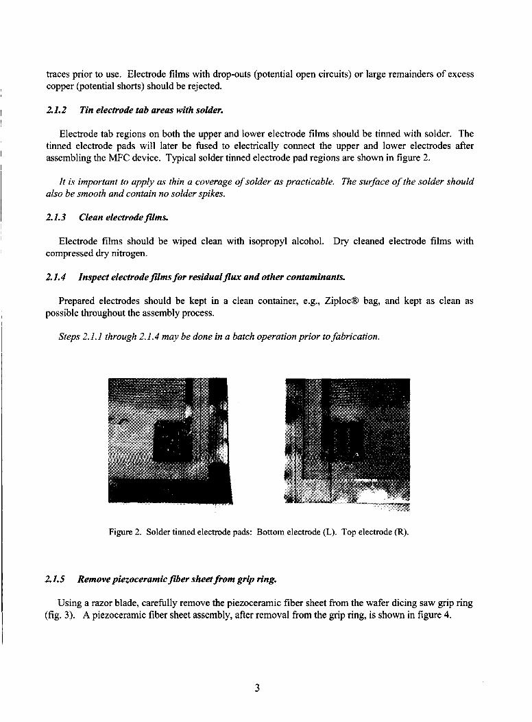
2.1.2 Tin electrode tab areas with solder.
Electrode tab regions on both the upper and lower electrode films should be tinned with solder. The tinned electrode pads will later be fused to electrically connect the upper and lower electrodes after assembling the MFC device. Typical solder tinned electrode pad regions are shown in figure 2.
It is important to apply as thin a coverage of solder as practicable. The surface of the solder should also be smooth and contain no solder spikes.
2.1.3 Clean electrode films.
Electrode films should be wiped clean with isopropyl alcohol. Dry cleaned electrode films with compressed dry nitrogen.
2.1.4 Inspect electrodefilms for residualflux and other contaminants.
Prepared electrodes should be kept in a clean container, e.g., ZiplocR bag, and kept as clean as possible throughout the assembly process.
Steps 2.1. I through 2. I .4 may be done in a batch operation prior to fabrication.
Figure 2. Solder tinned electrode pads: Bottom electrode (L). Top electrode (R).
2.1.5 Remove piezoceramic fiber sheet from grip ring.
Using a razor blade, carefully remove the piezoceramic fiber sheet fkom the wafer dicing saw grip ring (fig. 3). A piezoceramic fiber sheet assembly, after removal fiom the grip ring, is shown in figure 4.
3
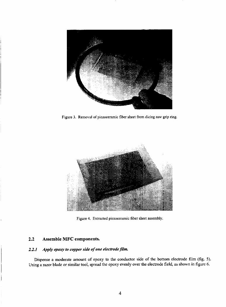
Figure 3. Removal of piezoceramic fiber sheet from dicing saw grip ring.
Figure 4. Extracted piezoceramic fiber sheet assembly.
2.2 Assemble MFC components.
2.2.1 Appb epoxy to copper side of one electrodefilm.
Dispense a moderate amount of epoxy to the conductor side of the bottom electrode film (fig. 5) . Using a razor blade or similar tool, spread the epoxy evenly over the electrode field, as shown in figure 6.
4

Figure 5. Dispensing of epoxy adhesive to electrode film.
Figure 6. Use of razor/doctor blade to distribute epoxy on electrode film.
The copper electrodes serve as a spacer that will determine the amount of epoxy remaining on the film. Ideally, all of the epoxy is removed from the top surface of the copper electrodes. Do not create dry areas on the film by excessively wiping across the film. During this stage, only the area that will be underneath the ceramic should be coated with epoxy. This makes it easier to remove the part from the lay-up stack after partial cure.
5

2.2.2 Apply epoxy to piezoceramicfiber sheet
Clean any contaminants from the piezoceramic using compressed dry nitrogen, and then apply a bead of epoxy along the end of the piezoceramic material, as shown in figure 7. Push the epoxy back and forth across the surface several times with the razor blade to force some epoxy down into the spaces between piezoceramic fibers (fig. 8). On the final pass, push the razor blade along the fibers with the blade facing forward, as shown in figure 9. This will minimize the amount of excess epoxy remaining on the piezoceramic surface.
Figure 7. Dispensing epoxy onto piezoceramic fiber sheet.
Figure 8. Distributing epoxy across piezoceramic fiber sheet.
6
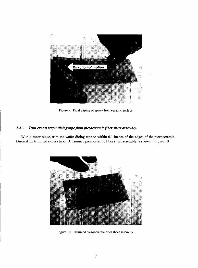
Figure 9. Final wiping of epoxy from ceramic surface.
~
2.2.3 Trim excess wafer dicing tape from piezoceramic _fiber sheet assembly. I I
With a razor blade, trim the wafer dicing tape to within 0.1 inches of the edges of the piezoceramic. Discard the trimmed excess tape. A trimmed piezoceramic fiber sheet assembly is shown in figure 10.
Figure 10. Trimmed piezoceramic fiber sheet assembly.
7

2.2.4 Place electrode film on piezoceramic sheet.
Invert the epoxy-wetted bottom electrode film pattern and position it on top of the piezoceramic, as shown in figure 1 1. Flip the film and piezoceramic combination so that the electrode film pattern is now on the bottom and the wafer dicing tape holding the ceramic together is dn top. Carefully slide the diced ceramic fibers into their proper position relative to the electrode pattern by pushing with your fingers, as shown in figure 12. This constitutes an MFCpurtiul assembly, as seen in figure 13.
Figure 1 1 . Lowering of bottom electrode film onto piezoceramic fiber sheet.
Figure 12. Manual alignment of piezoceramic fiber sheet on bottom electrode pattern.
8

Figure 13. MFC partial assembly.
2.2.5 Place partial assembly in the vacuum press stack lay-up.
Refer to appendix C for a description of the stack materials and lay-up order.
2.2.6 listed in appendix D.
Perform a partial cure of the MFCpartial assembly in a vacuum press utilizing the parameters
Extreme care should be taken during this stage to ensure that the partial assembly is not over-cured. At the completion of this step, the epoxy should be cured enough to hold the fibers in place, but it should not be hard.
I
At NASA Langley Research Center, the preferred apparatus for consolidating MFC components is a Wabash Model V40-I 81 8-2TMx Laminating Vacuum Press.. Operational procedures for using the Wabash press to consolidate MFC assemblies are given in appendix E.
I 2.2.7 Remove wafer dicing tape from piezoceramic fibers.
Remove the partial assembly from the press lay-up stack. Starting in one corner, carefully peel the wafer dicing tape from the ceramic, as shown in figure 14. The exposed piezoceramic fibers, now transferred to the bottom electrode film, are shown in figure 15.
* Product of Wabash MPI, 1569 Morris St, P.O. Box 298, Wabash, IN 46992-0298 USA.
9
Figure 14. Removal of wafer dicing tape from piezoceramic fibers.
Figure 15. Piezoceramic fibers transferred to bottom electrode film.
10
Inspect the exposed ceramic to be sure that no slivers of tape or other debris are present. Remove any foreign particles with tweezers or other suitable instruments prior to proceeding to the next step.
2.2.8 Apply epoxy film to the top electrode pattern.
Repeat step 2.2.1 for the opposite electrode film. A new mixing nozzle is used for this step. Ensure the film is wet with epoxy from edge to edge, excluding any copper border that will eventually be trimmed away.
2.2.9 Apply epoxy to exposed piezoceramic fibers.
Repeat step 2 to coat the exposed side of the ceramic. Ensure there is a thin layer of epoxy all the way to the edges of the pattern area of the film. No epoxy should be on the soldered pads.
2.2.1 0 Place remaining electrode film onto MFC partial assembly.
Invert the top electrode film pattern, so that the copper electrodes are facing down. Lower it onto the partially cured bottom electrode fildceramic assembly, as shown in figure 16, being careful to align both copper patterns. A careful visual alignment of the upper and lower electrode patterns generally yields satisfactory performance in the completed MFC package. The completed MFC assembly, ready for final vacuum press curing, is shown in figure 17.
Figure 16. Placement of top electrode film onto MFC partial assembly.
1 1
Figure 17. MFC assembly prior to final vacuum press curing.
2.2. I1 Place the completed MFC assembly in a new vacuum press lay-up stack.
Refer to appendix C again for a description of the stack.
2.2.12 Perform a full cure of the MFC assembly in the vacuum press.
Utilize the parameters listed in appendix D for the full-cure process.
2.2.13 Remove the MFC device from press lay-up stack
The assembled MFC device, prior to trimming excess film and copper, is shown in Figure 18.
Figure 18. Cured MFC package.
12
3
3.1
Inspect MFC assembly and connect electrodes.
Inspect MFC assembly for defects.
The MFC unit should be visually inspected for defects prior to poling. The most significant defects are pockets of entrapped air, or voids, spanning electrode fingers. Epoxy voids provide a potentially low dielectric breakdown pathway in the package, and will result in electrical shorts when voltage is applied to the electrodes.
MFC packages with large epoxy voids should be rejected.
Secondary defects include poor fiber alignment or shifting of fibers, and cracks across fibers. These defects typically will not directly cause electrical faults or failures in the package, but can result in
~
I I I undesirable nonuniformities in package mechanical properties.
Packages with secondary defects, in general, should be rejected.
3.2 Trim excess film and copper from MFC assembly.
Carefully remove excess polyimide film and copper from the perimeter of the device. Leave a minimum 1 mm polyimide border around the device. A trimmed MFC device is shown in figure 19.
I Figure 19. Trimmed MFC device.
3.4 Record trimmed weight of MFC device.
I A measurement, and record, of the trimmed weight of the MFC device is typically made at this point I for reference purposes.
13

3.5 Electrically connect upper and lower electrodes.
The electrode patterns on the top and bottom electrode film patterns are soldered to form a permanent electrical connection between them. The standard MFC electrode design includes features that accomplish this and provide an attachment point for electrical test leads or connectors. The electrical connection procedure used with the standard MFC package is described here.
Using a razor blade, carefully score the polyimide film around the perimeter of the slot where the test lead will be attached, as shown in figure 20. Remove the polyimide film, including residual cured epoxy below it, to expose the soldered surface of the lower electrode tab (fig. 2 1).
Figure 20. Scoring of polyimide over electrode tab solder.
Figure 2 1. Removal of polyimide over solder.
14

This is a delicate operation, and care needs to be taken not to cut all the way through the bottom electrode film. Apply heat from a soldering iron to reflow the solder (fig. 22). Flux and additional wire solder typically are used to ensure gqod wetting between the upper and lower solder tinned tabs. Remove any flux residue with isopropyl alcohol.
Figure 22. Reflowing of solder to connect upper and lower electrodes.
A wire test lead or connector may also be lap-soldered to the solder tinned slot at this time. A complete MFC with attached test lead wires is shown in figure 23.
Figure 23. Completely assembled MFC device with attached test leads.
15

4 Poling Procedure
Type* MFC I
The final step in the MFC manufacturing process is to electrically pole the device. Customarily, several electrical properties of the MFC device are also measured and recorded at this time. These measurements are made twice; prior to poling and immediately after poling.
Interdigitated electrode spacing 0.042 in I3000V
I DC Poling voltage
4.1 Record pre-poled room temperature electrical properties.
Using an electrical impedance analyzer, or equivalent instrument, measure and record the following room-temperature electrical properties of the un-poled MFC:
capacitance (C)
dissipation factor (0)
0 impedance (14)
phase angle (8 )
0 inductance (L )
quality factor (e) A11 measurements are to be made at a test frequency of I kHz, and a test signal amplitude of I V. Note
that the actuator should be mechanically unconstrained while making these measurements.
4.2 Poling.
After recording the pre-poled electrical properties, poling of the device can be performed. A high Poling at room temperature (25" C) will yield satisfactory voltage DC source is used to pole.
performance in standard MFC actuators. The following procedure is used to pole standard MFC devices:
Poring Procedure: Starting at 0 volts, increment a DC voltage in 100 volt increments until reaching the designated poling voltage level. Poling voltages for standard MFC devices are given in Table 1. Allow a delay of 15 seconds between voltage increments to allow the device to relax. Maintain the poling voltage for five minutes. At the end of the holding period, the voltage may be reduced to 0 volts in one step.
Table 1. Poling Voltages for Standard MFC Devices.
I MFCII I 0.021 in I 1500V
* See appendix A for detailed descriptions of MFC I and MFC II interdigitated electrode patterns.
4.3 Record post-poled room temperature electrical properties.
Short the electrode leads for several minutes to allow residual charges to dissipate, and then measure and record post-poled electrical properties, as listed in section 4.1. The MFC device is now completely functional and ready for use.
16

Summary
A complete method used for manufacturing research-standard Macro-Fiber Composite piezoelectric actuators was documented in this manuscript. This method has been used to fabricate over 400 MFC actuators at NASA Langley Research Center with satisfactory results. No claim is made that the MFC fabrication process described herein is “optimal,” or yields MFC devices with the best possible performance. This method does, however, produce MFC devices with consistent properties and repeatable performance. Devices manufactured using this process have exhibited variations in performance of less than 5% between units. The process is also relatively high-yield, with a successful poling rate of over 95%. Following these procedures exactly as described will enable the reader to produce piezocomposite actuator devices with equivalent properties.
I
17
Appendix A
Material Length Width Thickness
Specifications for Standard MFC Sub-Components and Materials
CTS Wireless Components 3 195HD lead-zirconate-titanate variable (3.375 to 5.5 inches typical) variable (1 .O to 2.5 inches typical) 0.007 in
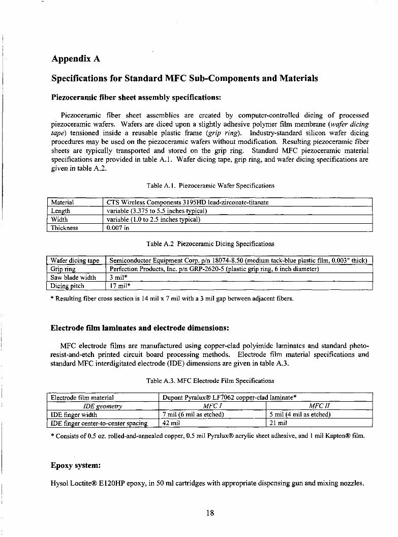
Piezoceramic fiber sheet assembly specifications:
Wafer dicing tape Grip ring Saw blade width Dicing Ditch
Piezoceramic fiber sheet assemblies are created by computer-controlled dicing of processed piezoceramic wafers. Wafers are diced upon a slightly adhesive polymer film membrane (wafer dicing tape) tensioned inside a reusable plastic frame k i p ring). Industry-standard silicon wafer dicing procedures may be used on the piezoceramic wafers without modification. Resulting piezoceramic fiber sheets are typically transported and stored on the grip ring. Standard MFC piezoceramic material specifications are provided in table A. 1. Wafer dicing tape, grip ring, and wafer dicing specifications are given in table A.2.
Semiconductor Equipment Corp. p/n 18074-8.50 (medium tack-blue plastic film, 0.003" thick) Perfection Products, Inc. p/n GRP-2620-5 (plastic grip ring, 6 inch diameter) 3 mil* 17 mil*
Table A. 1. Piezoceramic Wafer Specifications
IDE geometry MFC I I MFC II
* Resulting fiber cross section is 14 mil x 7 mil with a 3 mil gap between adjacent fibers.
Electrode film laminates and electrode dimensions:
MFC electrode films are manufactured using copper-clad polyimide laminates and standard photo- resist-and-etch printed circuit board processing methods. Electrode film material specifications and standard MFC interdigitated electrode (IDE) dimensions are given in table A.3.
Table A.3. MFC Electrode Film Specifications ~~ ~
(Electrode film material I Dupont F'yraluxB LF7062 copper-clad laminate*
I IDE finger center-to-center spacing 1 42 mil 121rnil
* Consists of 0.5 oz. rolled-and-annealed copper, 0.5 mil F'yraluxB acrylic sheet adhesive, and 1 mil KaptonB film.
Epoxy system:
Hysol LoctiteB E120HP epoxy, in 50 ml cartridges with appropriate dispensing gun and mixing nozzles.
18

Appendix B
Vendor Contact Information for Standard MFC Materials and Services
Piezoceramic wafers: I
I
CTS Wireless Components 4800 Alameda NE Albuquerque, NM 87 1 13 Phone: (505) 348-4361
I Fax: (505) 348-4617
I Electrode film laminates and processing:
GC Aero 3 165 Fujita Street Torrance, California 90505 Phone: (3 10) 539-7600 Fax: (3 10) 326-7903
Ceramic dicing products and services:
American Dicing 344 East Brighton Ave. Syracuse, NY 132 10 Phone: (315) 428-1200
i I Fax: (3 15) 428-121 1
I Semiconductor Equipment Corporation 5 154 Goldman Ave. Moorpark, California 93020-8079 Phone: (805)529-2293, Ext. 11
I
I
, Fax: (805)529-2 193
Perfection Products, Inc. 1320 South Indianapolis Ave. Lebanon, IN 46052 Phone: (765) 482-7786 Fax: (765) 482-7792
Epoxy materials and accessories:
Applied Industrial Technologies 2 100 Mingee Drive Hampton, VA Phone: (757) 838-4390
19

Appendix C
Building the Vacuum Press Stack Lay-Up
MFC vacuum press operations are performed using a stack of padding materials. The press-pad stack serves three primary purposes: 1) cushioning the assembly undergoing lamination, 2) facilitating the application of uniform pressure to the assembly, and 3) providing a release mechanism to enable the assembly to be removed from the stack after curing.
The most common combination or materials* used for manufacturing MFC devices, from top to bottom, is as follows:
0 1/8” thick aluminum top plate
o Pacothane Plus8 plastic film
o Equalizor 90@ press pad
o Airtech Wrightlon 4600 B l u e 0 release film
. MFC assembly (partial or complete)
o Airtech Wrightlon 4600 Blue@ release film
o Equalizor 9 0 8 press pad
o Pacothane Plus@ plastic film
0 1 /8” thick aluminum bottom plate
* Brand names of product are for reference only. Functionally equivalent products may be substituted with caution.
Length and width of press pad materials will vary based on the intended size of the MFC assembly. Typically, a minimum border of one-inch around the untrimmed MFC package should be used for all layers. Note that the order of materials in the stack is symmetric about the MFC assembly.
20

Appendix D
Operation Target temperature Stack pressure* Initial vacuum dwell Room temperature none Epoxy partial cure 115" F 70 psi Epoxy full cure 250" F 70 psi
MFC Cure Cycle Parameters for Loctitem E-120HP Epoxy
Duration at temperature and pressure 15 minutes (minimum) 3-5 minutes (maximum) 2 hours (minimum)
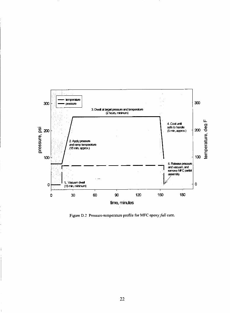
The preferred adhesive system for assembling the standard MFC device is LoctiteB E-120" epoxy. Nominal cure cycle parameters for use with this epoxy system only are provided in table D. 1. Typical pressure-temperature profiles for partial and full cure processing are shown in figures D.l and D.2 Additional information on cure processing of standard MFC devices may be found in reference 3.
Table D. 1. MFC Cure Processing Parameters
140
120
100
-- 80 3
20
0
0 10 20 30 40
time, minutes
140
120
100
20
0
Figure D. 1 Pressure-temperature profile for MFC epoxy partial cure.
21
0 30 60 90 120 150 180
time, minutes
Figure D.2 Pressure-temperature profile for MFC epoxy full cure.
22

Appendix E
Operation of Wabash Model V40-1818-2TMX Laminating Vacuum Press
Note: The press should be allowed to warm up for 20-60 minutes prior to use.
STEP 1: Ensure all controls are in their home state prior to pulling out the power o d o f f switch.
Home state is defined as follows:
0 All switches in the off position, including Heat or Cool Selector switch, Air switch, Vacuum switch, and Chart Recorder switch.
0 Manual pressure adjustment tuned to near zero pounds of force.
0 Pressure switch set to High.
0 Programmer switch set to Hold.
0 Manual or Program switch set to Manual.
STEP 2: Verify the limit switch trip mechanism located below the vacuum chamber door is positioned properly such that the limit switch will be triggered to activate the automatic slowdown and ultimate closure of the platens.
STEP 3: Power On
STEP 4: After a warm-up period, insert the stack containing the MFC unit(s) into the press.
Steel plates are typically used as spacers inside the press to make sure the upper and lower press platens never have less than 1 inch clearance between them. The MFC stack is placed on top of the steel plates.
STEP 5: Close and shut clamps on the vacuum chamber door.
STEP 6: Turn on the vacuum and let it run for 15 minutes prior to proceeding to the next step.
STEP 7: Turn the Heat or Cool Selector switch to the Heat position.
STEP 8: depressing the pushbutton on the controllers.
Adjust the temperature set point for all four zones by turning the adjustment wheel while
The adjustment wheel is located underneath a door on each controller that covers the lower half of the controller. Typically all four controllers will be set to the same temperature.
STEP 9: of the control panel.
Close the platens by simultaneously depressing the two green pushbuttons on the bottom
Once the platens are nearly closed, a yellow indicator lamp is illuminated indicating that further closure will be accomplished automatically at a prescribed slow rate. It is this function that highlights the
23
importance of properly adjusting the limit switch trip mechanism.
STEP 10: until the desired force is reached.
Once the platens are fully closed, slowly adjust the Manual Pressure Adjustment control
Note: Press force is determined by multiplying the stack aluminum plate area by the nominal processing stack pressure, as given in appendix D.
STEP 11: C.
Maintain appropriate time at temperature, as per the processing parameters in appendix
Once the time-at-temperature parameter has been met, opening the press for removal of the part is essentially the reverse of the previous steps.
STEP 12: Turn the Heat or Cool Selector switch to cool.
This will remove the electrical current from the heating elements of the press, and open valves permitting cooling water to flow through the platens. Leave the switch in this position until the temperature as indicated by the four controllers is in a range that will enable safe handling of the part stack. The safe handling temperature typically is between 90 and 95 degrees F.
STEP 13: Heat or Cool Selector switch to the Off position.
Once controller temperature is at a safe handling temperature (<95 degrees F), turn the
STEP 14: Turn the Vacuum switch to the Off position.
STEP 15: Turn the Air switch to the On position, and leave On for 15 - 20 seconds.
The purpose of this is to clear the cooling lines of water.
STEP 16: knob counterclockwise until the force on the platens is minimized.
Slowly remove the pressure from the platens by turning the Manual Pressure Adjustment
It is important to remove the pressure from the platens prior to proceeding to the next step.
STEP 17: Open the platens by depressing the yellow Clamp Open switch on the bottom of the control panel. Depress the switch firmly until the platens are filly opened, as indicated by the location of limit switch trip mechanism.
STEP 18: Open the vacuum chamber door and remove the stack containing the MFC unit.
24
References
1. Wilkie, W. Keats, et al, “Piezoelectric Macro-Fiber Composite Actuator and Method for Making Same,” U.S. Patent Application Publication US 20031005635 1 Al, March 27,2003.
2. Wilkie, W. K., High, J. W., Mirick, P. H., Fox, R. L., Little, B. D., Bryant, R. G., Hellbaum, R. F., Jalink, A., Jr., “Low-Cost Piezocomposite Actuator for Structural Control Applications,” presented at Industrial and Commercial Applications of Smart Structures Technologies, SPIE 7th International Symposium on Smart Structures and Materials, Newport Beach, California, March 5-9, 2000.
3. Williams, R. B., Grimsley, B. W., Inman, D. J. and Wilkie, W. K., “Manufacturing and Mechanics-Based Characterization of Macro Fiber Composite Actuators,” in proceedings of 2002 ASME International Adaptive Structures and Materials Systems Symposium, New Orleans, LA, November 17-22,2002.
25
I Form Approved OMB No. 0704-0188 REPORT DOCUMENTATION PAGE
Public reporting burden lor this collection of information is estimated to average 1 hour per response, including the time for reviewing instructions, searching existing data sources. gathering and maintaining the data needed, and completing and reviewing the collection of information. Send comments regarding this burden estimate or any Other aspect of this collection of information, including suggestions for reducing this burden, to Washington Headquarters Services. Directorate for Information Operations and Reports. 1215 Jefferson Davis Highway, Suite 1204, Arlington, VA 22202-4302, and to the Office of Management and Budget, Paperwork Reduction Project (0704-0188).
NASA Langley Research Genie; U.S. Army Research Laboratory Hampton, VA 2368 1-2 199 Vehicle Technology Directorate
NASA Langley Research Center Hampton, VA 2368 1-2 199
Washington. DC 20503
1. AGENCY USE ONLY (Leave blank) 2. REPORT DATE 3. REPORT TYPE AND DATES COVERED June 2003 Technical Memorandum
4. TITLE AND SUBTITLE I 5. FUNDING NUMBERS
REPORT NUMBER
L-18237
Method of Fabricating NASA-Standard Macro-Fiber Composite Piezoelectric Actuators
12a. DlSTRlBUTlONlAVAlLABlLlTY STATEMENT
Unclassified-Unlimited Subject Category 39 Distribution: Standard Availability: NASA CAS1 (301) 62 1-0390
755-06-00-1 1
12b. DISTRIBUTION CODE
6. AUTHOR(S) James W. High and W. Keats Wilkie
14. SUBJECT TERMS Actuators, piezoceramic, piezoelectricity, composites
17. SECURITY CLASSIFICATION 18. SECURITY CLASSIFICATION 19. SECURITY CLASSIFICATION OF ABSTRACT OF REPORT OF THIS PAGE
Unclassified Unclassified Unclassified
I
7. PERFORMING ORGANIZATION NAMEIS) AND ADDRESSIES) I 8. PERFORMING ORGANIZATION
15. NUMBER OF PAGES 30
16. PRICE CODE
20. LIMITATION OF ABSTRACT
UL
I
9. SPONSORlNGlMONITORlNG AGENCY NAME(S) AND ADDRESS(ES) I 10. SPONSORING/MONITORING
National Aeronautics and Space Administration Washington, DC 20546-0001
U.S. Army Research Laboratory and
AGENCY REPORT NUMBER
NASAITM-2003-2 12427 ARL-TR-2833
Adelphi, MD 20783-1 145 I 11. SUPPLEMENTARY NOTES