METHOD AND APPARATUS OF ESTABLISHING A …
23
Note: Within nine months of the publication of the mention of the grant of the European patent in the European Patent Bulletin, any person may give notice to the European Patent Office of opposition to that patent, in accordance with the Implementing Regulations. Notice of opposition shall not be deemed to have been filed until the opposition fee has been paid. (Art. 99(1) European Patent Convention). Printed by Jouve, 75001 PARIS (FR) (19) EP 2 090 050 B1 & (11) EP 2 090 050 B1 (12) EUROPEAN PATENT SPECIFICATION (45) Date of publication and mention of the grant of the patent: 12.01.2011 Bulletin 2011/02 (21) Application number: 08734202.8 (22) Date of filing: 29.04.2008 (51) Int Cl.: H04L 27/26 (2006.01) (86) International application number: PCT/CN2008/070844 (87) International publication number: WO 2008/134976 (13.11.2008 Gazette 2008/46) (54) METHOD AND APPARATUS OF ESTABLISHING A SYNCHRONISATION SIGNAL IN A COMMUNICATION SYSTEM VERFAHREN UND EINRICHTUNG ZUM AUFBAU EINES SYNCHRONISIERSIGNALS IN EINEM VERMITTLUNGSSYSTEM PROCÉDÉ ET APPAREIL D’ÉTABLISSEMENT D’UN SIGNAL DE SYNCHRONISATION DANS UN SYSTÈME DE COMMUNICATION (84) Designated Contracting States: AT BE BG CH CY CZ DE DK EE ES FI FR GB GR HR HU IE IS IT LI LT LU LV MC MT NL NO PL PT RO SE SI SK TR (30) Priority: 02.05.2007 SE 0701056 (43) Date of publication of application: 19.08.2009 Bulletin 2009/34 (73) Proprietor: Huawei Technologies Co., Ltd. Longgang District, Shenzhen Guangdong 518129 (CN) (72) Inventor: POPOVIC, Branislav, M. SE-164 94 Kista, Stockholm (SE) (74) Representative: Körber, Martin Hans Mitscherlich & Partner Patent- und Rechtsanwälte Sonnenstraße 33 80331 München (DE) (56) References cited: EP-A1- 1 530 336 EP-A2- 1 505 787 CN-A- 1 780 276 • HUAWEI: "Cell-specific signals for initial synchronization and cell identification" 3GPP DRAFT; R1-060225, 3RD GENERATION PARTNERSHIP PROJECT (3GPP), MOBILE COMPETENCE CENTRE ; 650, ROUTE DES LUCIOLES ; F-06921 SOPHIA-ANTIPOLIS CEDEX ; FRANCE, vol. RAN WG1, no. Helsinki, Finland; 20060118, 18 January 2006 (2006-01-18), XP050111356 [retrieved on 2006-01-18] • PANASONIC ET AL: "RACH Zadoff-Chu sequence definition and allocation" 3GPP DRAFT; R1-071111, 3RD GENERATION PARTNERSHIP PROJECT (3GPP), MOBILE COMPETENCE CENTRE ; 650, ROUTE DES LUCIOLES ; F-06921 SOPHIA-ANTIPOLIS CEDEX ; FRANCE, vol. RAN WG1, no. St. Louis, USA; 20070206, 6 February 2007 (2007-02-06), XP050105102 [retrieved on 2007-02-06] • NEC GROUP: "Package of PSC and SSC proposals for LTE cell search" 3GPP DRAFT; R1-071497, 3RD GENERATION PARTNERSHIP PROJECT (3GPP), MOBILE COMPETENCE CENTRE ; 650, ROUTE DES LUCIOLES ; F-06921 SOPHIA-ANTIPOLIS CEDEX ; FRANCE, vol. RAN WG1, no. St. Julian; 20070403, 3 April 2007 (2007-04-03), XP050105430 [retrieved on 2007-04-03]
Transcript of METHOD AND APPARATUS OF ESTABLISHING A …

Note: Within nine months of the publication of the mention of the grant of the European patent in the European PatentBulletin, any person may give notice to the European Patent Office of opposition to that patent, in accordance with theImplementing Regulations. Notice of opposition shall not be deemed to have been filed until the opposition fee has beenpaid. (Art. 99(1) European Patent Convention).
Printed by Jouve, 75001 PARIS (FR)
(19)E
P2
090
050
B1
��&�� ���������(11) EP 2 090 050 B1
(12) EUROPEAN PATENT SPECIFICATION
(45) Date of publication and mention of the grant of the patent: 12.01.2011 Bulletin 2011/02
(21) Application number: 08734202.8
(22) Date of filing: 29.04.2008
(51) Int Cl.:H04L 27/26 (2006.01)
(86) International application number: PCT/CN2008/070844
(87) International publication number: WO 2008/134976 (13.11.2008 Gazette 2008/46)
(54) METHOD AND APPARATUS OF ESTABLISHING A SYNCHRONISATION SIGNAL IN A COMMUNICATION SYSTEM
VERFAHREN UND EINRICHTUNG ZUM AUFBAU EINES SYNCHRONISIERSIGNALS IN EINEM VERMITTLUNGSSYSTEM
PROCÉDÉ ET APPAREIL D’ÉTABLISSEMENT D’UN SIGNAL DE SYNCHRONISATION DANS UN SYSTÈME DE COMMUNICATION
(84) Designated Contracting States: AT BE BG CH CY CZ DE DK EE ES FI FR GB GR HR HU IE IS IT LI LT LU LV MC MT NL NO PL PT RO SE SI SK TR
(30) Priority: 02.05.2007 SE 0701056
(43) Date of publication of application: 19.08.2009 Bulletin 2009/34
(73) Proprietor: Huawei Technologies Co., Ltd.Longgang District, ShenzhenGuangdong 518129 (CN)
(72) Inventor: POPOVIC, Branislav, M.SE-164 94 Kista, Stockholm (SE)
(74) Representative: Körber, Martin HansMitscherlich & Partner Patent- und Rechtsanwälte Sonnenstraße 3380331 München (DE)
(56) References cited: EP-A1- 1 530 336 EP-A2- 1 505 787CN-A- 1 780 276
• HUAWEI: "Cell-specific signals for initial synchronization and cell identification" 3GPP DRAFT; R1-060225, 3RD GENERATION PARTNERSHIP PROJECT (3GPP), MOBILE COMPETENCE CENTRE ; 650, ROUTE DES LUCIOLES ; F-06921 SOPHIA-ANTIPOLIS CEDEX ; FRANCE, vol. RAN WG1, no. Helsinki, Finland; 20060118, 18 January 2006 (2006-01-18), XP050111356 [retrieved on 2006-01-18]
• PANASONIC ET AL: "RACH Zadoff-Chu sequence definition and allocation" 3GPP DRAFT; R1-071111, 3RD GENERATION PARTNERSHIP PROJECT (3GPP), MOBILE COMPETENCE CENTRE ; 650, ROUTE DES LUCIOLES ; F-06921 SOPHIA-ANTIPOLIS CEDEX ; FRANCE, vol. RAN WG1, no. St. Louis, USA; 20070206, 6 February 2007 (2007-02-06), XP050105102 [retrieved on 2007-02-06]
• NEC GROUP: "Package of PSC and SSC proposals for LTE cell search" 3GPP DRAFT; R1-071497, 3RD GENERATION PARTNERSHIP PROJECT (3GPP), MOBILE COMPETENCE CENTRE ; 650, ROUTE DES LUCIOLES ; F-06921 SOPHIA-ANTIPOLIS CEDEX ; FRANCE, vol. RAN WG1, no. St. Julian; 20070403, 3 April 2007 (2007-04-03), XP050105430 [retrieved on 2007-04-03]

2
EP 2 090 050 B1
• HUAWEI: "P-SCH sequences" 3GPP DRAFT; R1-072321, 3RD GENERATION PARTNERSHIP PROJECT (3GPP), MOBILE COMPETENCE CENTRE ; 650, ROUTE DES LUCIOLES ; F-06921 SOPHIA-ANTIPOLIS CEDEX ; FRANCE, vol. RAN WG1, no. Kobe, Japan; 20070503, 3 May 2007 (2007-05-03), XP050106051 [retrieved on 2007-05-03]

EP 2 090 050 B1
3
5
10
15
20
25
30
35
40
45
50
55
Description
CROSS-REFERENCE TO RELATED APPLICATIONS
[0001] The present application claims priority to application No. SE0701056.4 filed on May 2, 2007.
FIELD OF THE INVENTION
[0002] The technical field is communications and synchronisation. More particularly, the invention relates to, e.g.,synchronisation in OFDM (Orthogonal Frequency Division Multiplex) systems.
BACKGROUND
[0003] 3GPP Technical Specification, 3GPP TS 36.211 v1.0.0, 3rd Generation Partnership Project, Technical Spec-ification Group Radio Access Network, Physical Channels and Modulation (Release 8), France, March 2007, describesphysical channels for evolved UTRA.[0004] When specifying a synchronisation scheme for a communication system, of course many parameters have tobe weighed in order to optimise, in some sense, the performance of the system. That would be true both for the specificsynchronisation performance, where perhaps improving one design parameter may worsen another and vice versa, butalso for the performance of the communication system as a whole due to the chosen synchronisation scheme. Forinstance, for a wireless system there may be constraints on terminals in terms of power consumption, cost of device,radio reception sensitivity and so forth. Such constraints on communication systems and their constituents can beimposed both by standard regulating bodies, as well as by manufacturers themselves wanting to maximise incomegenerating power of their products. Designers of communication systems designing synchronisation schemes must bearthese problems of design in mind.[0005] A document for agenda item 7.2 of RAN WG1 meeting 48bis titled, Package of PSC and SSC proposals forLTE cell search, R1-071497 Malta, March 26 - 30, 2007, proposes a package of Primary Synchronisation Codes, PSC,and Secondary Synchronisation Codes, SSC, design for LTE cell search. The document presents a solution to theproblem of how to design PSC synchronisation sequences being Zadoff-Chu sequences of length 71, with root indicesu =1, 5 and 70.[0006] Another document for agenda item 7.2 of RAN WG1 meeting 48bis titled, Comparison of sequence and structurefor P-SCH, R1-071531 Malta, March 26 - 30, 2007, presents another proposal on how to design synchronization for E-UTRA. In the document, it was proposed to use Zadoff-Chu sequences of length 72, with no specified root indices u.[0007] A further document for agenda item 5.1.3.4 of 3GPP TSG RAN WG1 LTE Ad Hoc titled, Cell-specific signalsfor initial synchronization and cell identification, R1-060225, Helsinki, Finland, January 23-25, 2006, introduces centrallysymmetric signals and a blind reverse differential correlation detection algorithm for detection of the signals withoutknowledge of their exact waveform. The document also stresses the importance of PAPR (Peak-to-Average-Power-Ratio) values and concludes that all the OFDM synchronization signals, based on different Golay sequences from a setof orthogonal complementary pairs will have small PAPR values, allowing in that way the maximization of the averagetransmitted power, i.e. the maximization of the received SNR at the cell edge.A further document for agenda item 6.5.1 of 3GPP TSG RAN WG1 meeting 48bis titled, RACH Zadoff-Chu sequencedefinition and allocation, R1-071111, St. Louis, USA, February 12-16, 2007, discusses Zadoff-Chu sequence definitionand allocation on non-synchronized random access preamble in order to allow simpler implementation of the randomaccess preamble generation and detection. This document also discloses that frequency domain defined ZC sequencemakes use of the central symmetry or complex conjugate symmetry properties to reduce the number of multiplicationsneeded at the receiver.
SUMMARY
[0008] An object of example embodiments of the invention is to provide efficient synchronization for communications.According to an example embodiment of the invention, a method of establishing a synchronization signal suitable for,particularly, a matched filter receiver in a communication system including: defining a set of discrete Fourier frequencycoefficients; and transforming the set of discrete Fourier frequency coefficients into a discrete time representation.[0009] Further, the communication system is preferably prepared for using the discrete time representation as thesynchronization signal in the communication system.[0010] The set of discrete Fourier frequency coefficients is preferably defined so as to be centrally symmetric or isachieved from a mapping of a number sequence being centrally symmetric. The set of discrete Fourier frequencycoefficients is a set of Fourier frequency coefficients that is centrally symmetric, and said centrally symmetric number

EP 2 090 050 B1
4
5
10
15
20
25
30
35
40
45
50
55
sequence corresponds to puncturing a central element of a Zadoff-Chu sequence of odd length L+1.[0011] Specifying a synchronization signal based on Fourier frequency coefficients being centrally symmetric providesthe advantage of allowing for an efficient implementation of a corresponding bank of correlators in, e.g. a receiverreceiving such a signal.[0012] Another demonstrated merit of an embodiment of the invention is advantageous Peak-to-Average-Power-Ratio,PAPR.[0013] An object of a preferred example embodiment of the invention is to devise an improved or alternative synchro-nization scheme for a matched filter receiver.[0014] According to the invention, an example transmitter for a communication system is provided, the transmitterbeing arranged to send a synchronization signal to, e.g. a matched filter receiver in the communication system. Thesynchronization signal is preferably established from:
defining a set of discrete Fourier frequency coefficients; andtransforming the set of discrete Fourier frequency coefficients into a discrete time representation.
[0015] Further, the transmitter is preferably arranged to use the discrete time representation as the synchronizationsignal in the communication system.[0016] In a preferred mode of the invention, the discrete time representation is such that the set of discrete Fourierfrequency coefficients is centrally symmetric. The set of discrete Fourier frequency coefficients is a set of Fourier frequencycoefficients that is centrally symmetric, and said centrally symmetric number sequence corresponds to puncturing acentral element of a Zadoff-Chu sequence of odd length L+1.[0017] According to yet another aspect of the invention, an example receiver of, preferably, matched filter type for acommunication system is disclosed. The receiver is arranged to receive a synchronization signal in the communicationsystem and is adapted to the synchronization signal as established by:
defining a set of discrete Fourier frequency coefficients,transforming the set of discrete Fourier frequency coefficients into a discrete time representation,
where the receiver is preferably arranged to receive the discrete time representation as the synchronization signal inthe communication system.[0018] In a preferred mode, the discrete time representation is such that the set of discrete Fourier frequency coefficientsis centrally symmetric. The set of discrete Fourier frequency coefficients is a set of Fourier frequency coefficients thatis centrally symmetric, and said centrally symmetric number sequence corresponds to puncturing a central element ofa Zadoff-Chu sequence of odd length L+1.[0019] According to yet another example aspect of the invention, a communication system includes:
a transmitter arranged to send a synchronization signal; anda receiver, preferably of matched filter type, arranged to receive the synchronization signal;
where the synchronization signal is established from:
a set of discrete Fourier frequency coefficients being defined, andthe set of discrete Fourier frequency coefficients being transformed into a discrete time representation,
where the transmitter and receiver preferably is arranged to transmit and receive, respectively, the discrete time repre-sentation as the synchronization signal.[0020] In preferred modes of the invention, said transmitter and receiver are arranged to use said discrete time rep-resentation as said synchronisation signal, wherein said discrete time representation is such that said set of discreteFourier frequency coefficients is centrally symmetric.
BRIEF DESCRIPTION OF THE DRAWING(S)
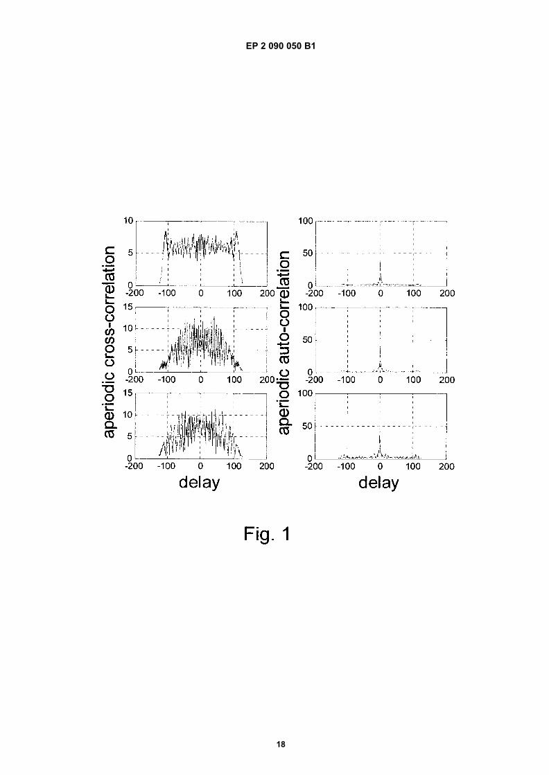
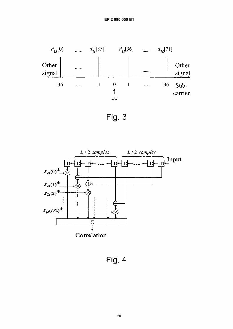
[0021] Embodiments exemplifying the invention are described by means of the appended drawings on which:[0022] Figure 1 illustrates, according to prior art, aperiodic correlation functions of P-SCH signals from the documentR1-071497 of RAN WG1 meeting 48bis, using 128 samples long correlators.[0023] Figure 2 illustrates, according to prior art, aperiodic correlation functions of P-SCH signals from the documentR1-071531 of RAN WG1 meeting 48bis, using 128 samples long correlators.[0024] Figure 3 illustrates schematically a resulting mapping of a P-SCH sequence to subcarriers, according to the

EP 2 090 050 B1
5
5
10
15
20
25
30
35
40
45
50
55
invention.[0025] Figure 4 illustrates schematically an efficient matched filter for P-SCH signal, defined by equation 5 for sequencelengths of N=L+1 samples, according to the invention.[0026] Figure 5 illustrates, according to the invention, aperiodic correlation functions of P SCH signals, as specifiedin equation 14, using 128 samples long correlators.[0027] Figure 6 illustrates schematically transmitter and receiver of an example communications system according tothe invention.
DETAILED DESCRIPTION
[0028] Downlink signals in, e.g., E-UTRA cellular system, based on OFDM transmission technology, are specified notto use the central frequency in the available bandwidth, the so-called DC subcarrier, for transmission. A reason for thisis that potential local-oscillator leakage, which can occur either in the transmitter of the base station or in the receiverof the mobile User Equipment, UE, can cause significant interference to the DC subcarrier, and thus make it practicallyunusable.[0029] The E-UTRA cellular system is specified to use multiple (three) Primary Synchronisation, P-SCH, signals,transmitted on the Down-Link, DL, to support the OFDM symbol timing synchronisation at the UE. The three P-SCHsignals are tied to the cell identities within a cell identity group, serving in that way both for timing synchronisationpurposes and information transmission.[0030] The P-SCH signals have non-repetitive structure, and are based on the Zadoff-Chu, ZC, sequences. The P-SCH signals are OFDM signals with up to 72 active subcarriers, centred around the DC subcarrier. The active subcarriersare modulated with the elements of a cell-specific P-SCH sequence du[n] selected from a set of three different ZCsequences with root indices u = u1, u2 and u3. The resulting mapping of an example P-SCH sequence du[n], n=0,...,71, of length L=72, to available subcarriers is schematically illustrated in figure 3. Reception at the UE of the synchro-nisation signal is preferably by way of a matched filter receiver. A matched filter can be shown to maximise the signalto noise ratio at the output of the filter in the instant of complete reception of the signal. The impulse response of thematched filter for the signal that has passed the Additive White Gaussian Noise, AWGN, channel is equal to the time-reversed version of the transmitted signal. Such matched filters are used in practice even if the propagation channel isnot AWGN, as a good approximation of the exact matched filter for such non-AWGN channels would require the knowledgeof the channel correlation function.[0031] Comparing the two proposals from RAN WG1 meeting 48bis, a trade-off made in the former is that one availablesubcarrier remains unused. This reduces the frequency diversity of the signal, making the signal more susceptible tothe effects of the fading propagation channel. Larger reduction of the signal bandwidth would lead to broadening of themain autocorrelation lobe of the signals, which would mean reduced accuracy of signal timing estimation. A drawbackof the latter proposal, Comparison of sequence and structure for P-SCH, RI -071531, compared to the former, Packageof PSC and SSC proposals for LTE cell search, R1-071497, is that the maximum cross-correlations of multiple PrimarySynchronisation, P-SCH, signals obtained from the different root indices of Zadoff-Chu sequences of length 72 arehigher than if the length of Zadoff-Chu sequences is 71.[0032] In order to improve or provide an alternative to the prior art, example embodiments of this invention proposesa method, system and apparatus for establishing a synchronisation signal, particularly well suited for a matched filterreceiver, in a communication system, the method including:
- a set of discrete Fourier frequency coefficients, Hu[l], being defined,- said set of discrete Fourier frequency coefficients, Hu[l], being transformed into a discrete time representation, su
[k], and- preparing said communication system for use of said discrete time representation, su[k], as said synchronisation
signal in said communication system.
[0033] The "preparing the communication system for use...," includes making the communication system ready to usethe specified synchronisation signal, for instance: by storing the signal in a memory somewhere in the system; orprogramming parts of the communication system in order to make use of the synchronisation signal, when transmittingor receiving.[0034] Said set of discrete Fourier frequency coefficients, Hu[l], is preferably defined so as to be centrally symmetric.It will be shown below, that if the frequency representation is centrally symmetric then that is a necessary and sufficientcondition for the discrete time representation su[k] also to be centrally symmetric. This means that the matched filterreceiver can be designed to be much more efficient than is the case for the abovementioned proposals of the RAN WG1meeting 48bis.[0035] One motivation of central symmetry of the signal in the present invention is a thereby achieved efficient imple-

EP 2 090 050 B1
6
5
10
15
20
25
30
35
40
45
50
55
mentation of a receiver, such as a matched filter receiver, for which the exact knowledge of the signal waveform is aprerequisite.[0036] One way to define the set of discrete Fourier frequency coefficients in an example method according to theinvention is to, for defining said set of discrete Fourier frequency coefficients, Hu[l], include in the example method:
- a number sequence, du[n], being defined, and- a mapping of the number sequence, du[n], being performed to arrive at a said set of discrete Fourier frequency
coefficients, Hu[l], that is preferably centrally symmetric,
[0037] This allows for a convenient way of defining the coefficients, Hu[l], that also conforms with the standard in 3GPPTechnical Specification. 3GPP TS 36.211 v1.0.0 and still retains the preferred property of central symmetry.[0038] Further on the method according to the present invention, the defining a number sequence du[n] preferablyalso includes defining said number sequence, du[n], to be centrally symmetric.[0039] Additionally, in a preferred embodiment of the invention said mapping is performed such as to have said setof discrete Fourier frequency coefficients Hu[l] with a DC-carrier being zero. This would be beneficial in systems havinga requirement for the DC-carrier to be zero, such as in 3GPP Technical Specification 3GPP TS 36.211 v1.0.0.[0040] As an example, a mapping according to the method of the invention is performed in accordance with:
where L is a length of said number sequence du[n] and N=L+1 is the number of discrete Fourier frequency coefficients,Hu[l]. This mapping would conform both with the preferred requirement of mapping a centrally symmetric number se-quence onto a set of centrally symmetric frequency coefficients as well as mapping said number sequence such thatthe set of frequency coefficients would have a DC-carrier being zero.[0041] Defining said number sequence could for instance involve defining said number sequence as a centrally sym-metric sequence, du[n], being of length L and having a property such that du[n]= du[L-1-n], n=0,1,...,L/2-1. So this wouldprovide central symmetry of du[n]. Said centrally symmetric number sequence, du[n], could be defined by concatenatinga number sequence of length L/2 and its reverted replica. As an example of this, a number sequence could be mentioned,wherein said centrally symmetric number sequence, du[n], is obtained by concatenating a Zadoff-Chu sequence oflength L/2 and its reverted replica, so that du[n] is given by
where WN=e-j2π/N, for positive integers N.[0042] Another way to obtain a centrally symmetric number sequence is by puncturing a central element of a Zadoff-Chu sequence of odd length L+1, so that du[n] is given by

EP 2 090 050 B1
7
5
10
15
20
25
30
35
40
45
50
55
where WN=e-j2π/N, for positive integers N.[0043] If the sequence du[n] is centrally symmetric, such that
then Hu[l] in equation 1 will also be centrally symmetric around the DC. This is a sufficient and necessary condition forthe time domain synchronisation signal, su[k], to be centrally symmetric, such that
[0044] It means that only the sample Su[0] does not have its symmetric counterpart. The proof of equation 5 is as follows:Starting from the definition of su[k],
it follows that
where we introduced the change of variables n=N-1, reordered the summation and used periodicity of the DFT{Hu[n]=Hu[n+N]}. From abovementioned relations, it follows that su[k]=su[N-k] if Hu[n]=Hu[N-n], which is a sufficient condition.It is also a necessary condition, meaning that only if Hu[n]=Hu[N-n] it will be that su[k]=su[N-k], as it can be shown bystarting from the expression for Hu[n].[0045] In an applied case, if we define said centrally symmetric sequence to have a length L=72, we can compare itsperformance with that achievable from sequences of abovementioned prior art proposals of RAN WG1 meeting 48bis.Compared to the first of these cited documents, it provides utilization of all available active subcarriers for P-SCH signals.Compared to both cited proposals of RAN WG1 meeting 48bis, it yields synchronisation signals with very low pair-wiseaperiodic cross-correlations, very low autocorrelation side lobes of synchronisation signals, and low Peak-to-Average-Power-Ratio, PAPR, as will be discussed below.[0046] Of course, the choice of the length L of du[n] is not limited to this example length and would depend on theapplication. As an example, it is perfectly possible for said centrally symmetric sequence to have a length L=64.[0047] In the method according to the invention, said transforming recited above, could include transforming of Fourier

EP 2 090 050 B1
8
5
10
15
20
25
30
35
40
45
50
55
frequency coefficients, Hu[l], l=0,1,...N-1, such that su[k]= WN=exp(-j2π/N), k=0,...N-
1. This is the Inverse Discrete Fourier Transform. In a communication system where such a transforming is performed,it could be implemented with any suitable algorithm that enables fast computation. It is of course also possible to havesaid discrete time representation su[k] calculated in advance and stored in a memory somewhere in the communication
system.[0048] The described method of establishing a synchronisation signal in a communication system according to theinvention could be used for establishing synchronisation signals in different communication systems requiring some sortof synchronisation, for instance, establishing such synchronisation signals for a communication system being a wirelesscommunication system. One example of such a wireless communication system is an OFDM-downlink channel in acellular communication system. Such a system is described in 3GPP Technical Specification, 3GPP TS 36.211 v1.0.0.[0049] It should be stated that all features of the method according to the invention described above and all theirdifferent alternatives can be combined arbitrarily, just as long as such combinations does not imply a self-contradiction.[0050] As an example, we now use the insights of the invention applied to the case of a system according to the onespecified in 3GPP Technical Specification, 3GPP TS 36.211 v1.0.0 and compare the performance of that applied casewith that of abovementioned prior art proposals of RAN WG1 meeting 48bis. As specified in 3GPP Technical Specification,3GPP TS 36.211 v1.0.0, and shown in figure 3, the DC subcarrier cannot be used for mapping the elements of sequencedu[n], while the elements of du[n] are mapped to all other consecutive, equally-spaced subcarriers around the DCsubcarrier. The baseband P-SCH signal su[k], k=0,1,...,N-1, from figure 3 is e.g. obtained by N-point IDFT (InverseDiscrete Fourier Transform) of the spectrum of N Fourier coefficients Hu[l], l=0,1,..., N-1, as
where du[n], n=0,1,...,L-1, is the example P-SCH sequence of length L=72.[0051] As an illustration, the proposal R1-071497 of RAN WG1 meeting 48bis describes P SCH sequences given by
[0052] The aperiodic cross/auto-correlation functions of the P-SCH signals from R1-071497 of RAN WG1 meeting48bis, for 128 samples long correlators, are shown in figure 1. The PAPR values of these signals are 3.14 dB, 3.14 dBand 4.66 dB.[0053] As another illustration, the proposal R1-071531, of RAN WG1 meeting 48bis can be described by P-SCHsequences given by

EP 2 090 050 B1
9
5
10
15
20
25
30
35
40
45
50
55
[0054] The aperiodic cross/auto-correlation functions of the P-SCH signals in proposal R1-071531 from RAN WG1meeting 48bis, for 128 samples long correlators, and for u=1, 71 and 5, are shown in figure 2. The PAPR values of thesesignals are 2.61 dB, 2.57 dB and 6.78 dB.[0055] The central symmetry of N-1 samples of a P-SCH signal can be used to reduce the number of multiplicationsin an example matched filter corresponding to the P-SCH signal. For example, if N=L+1=73, there are 72 centrallysymmetric samples of P-SCH signal, so the matched filter can be implemented by 1+72/2=37 multiplications per singlecorrelation, which is a reduction of about 50% compared to the direct implementation, which requires 73 multiplications.It is illustrated in figure 4, where "*" denotes complex conjugation.[0056] Below, two procedures or ways to obtain an example P-SCH sequence, du[n], which is centrally symmetricbased on a Zadoff-Chu, ZC, sequence are discussed.[0057] The first way is to concatenate the ZC sequence of length L/2 and its reverted replica. The corresponding P-SCH sequences, du[n], are given by equation 2:
[0058] The second way is to puncture the central element of a ZC sequence of odd length L+1. In that case the P-SCH sequences, du[n], are given by equation 3:
[0059] The second alternative provides example P-SCH signals with lower maximum cross-correlations.[0060] From the above discussion, it follows that it is beneficial to define the three different example P-SCH sequences,du[n], of length 72 as obtained by puncturing the central elements of different ZC sequences of length 73, i.e. as
[0061] The aperiodic cross/auto-correlation functions of the P-SCH signals obtained from equation 14, using 128samples long correlators, are shown in figure 5. The PAPR values achieved in accordance with the invention are 2.98dB, 2.98 dB and 4.43 dB, i.e., better than or corresponding to PAPR-values of prior art.[0062] As the Zadoff-Chu sequence of length L+1 with the root index u3=L+1-u1 is the complex conjugated versionof the ZC sequence of the same length with the root index u1, the two corresponding matched filters can be implementedwith the multiplication complexity of just one filter.[0063] Specifying a synchronisation signal based on Fourier frequency coefficients being centrally symmetric benefits

EP 2 090 050 B1
10
5
10
15
20
25
30
35
40
45
50
55
from an insight not revealed in the abovementioned background-documents for RAN WG1 meeting 48bis, namely thattransmission of such a synchronisation signal provides the advantage of allowing for an efficient implementation of acorresponding bank of correlators in, e.g., a receiver receiving such a signal. This benefit is surprising in view of whatcan be achieved from the teachings of the prior-art documents.[0064] Another demonstrated merit of an embodiment of the invention is advantageous Peak-to-Average-Power-Ratio,PAPR.[0065] According to an embodiment of the invention, the invention encompasses a transmitter for a communicationsystem, said transmitter being arranged to send a synchronisation signal for, e.g., a matched filter receiver in saidcommunication system, wherein said synchronisation signal is established from:
- a set of discrete Fourier frequency coefficients, Hu[l], being defined, and- said set of discrete Fourier frequency coefficients, Hu[l], being transformed into a discrete time representation, su[k],
said transmitter preferably being arranged to use said discrete time representation, su[k], as said synchronisation signalin said communication system.[0066] In an example embodiment, the transmitter is arranged to use said discrete time representation, su[k], as saidsynchronisation signal in said communication system, wherein said discrete time representation, su[k], is such that saidset of discrete Fourier frequency coefficients, Hu[l], is centrally symmetric.[0067] Figure 6 illustrates schematically transmitter, Tx, (61) and receiver, Rx, (65) of an example communicationssystem according to the invention.[0068] Basically, the transmitter can be arranged to perform any feature, from a transmitting viewpoint, of the methodaccording to the invention, described above, as desired for a particular application. The transmitter is arranged to usethe discrete time representation, su[k], as said synchronisation signal in said communication system. This implies thatit is provided with structures to put the synchronisation signal in use. Non-exclusive examples of such structures includeelectronic memory, MT, (64) a microprocessor, KT, (62) and circuitry for sending electric signals, Tc (63).[0069] In one embodiment of the invention, the invention encompasses a receiver of the matched filter type for acommunication system, said receiver being arranged to receive a synchronisation signal in said communication system,where said synchronisation signal is established from:
- a set of discrete Fourier frequency coefficients, Hu[l], being defined,- said set of discrete Fourier frequency coefficients, Hu[l], being transformed into a discrete time representation, su[k],
said receiver preferably being arranged to receive said discrete time representation, su[k], as said synchronisation signalin said communication system.[0070] In an example embodiment, the receiver is arranged to use said discrete time representation, su[k], as saidsynchronisation signal in said communication system, wherein said discrete time representation, su[k], is such that saidset of discrete Fourier frequency coefficients, Hu[l], is centrally symmetric.[0071] Basically, the receiver can be arranged to perform any feature, from a receiving viewpoint, of the methodaccording to the invention, described above, as desired for a particular application. The receiver is preferably arrangedto use the discrete time representation, su[k], as said synchronisation signal in said communication system. This impliesthat it is provided with structures to put the synchronisation signal into use. Non-exclusive examples of such structuresinclude electronic memory, MR, (68) a microprocessor, KR, (66) and circuitry for receiving electric signals, Rc (67).[0072] In one example embodiment of the invention, the invention encompasses a communication system including:
- a transmitter being arranged to send a synchronisation signal for an example matched filter receiver, and- a receiver, of the example matched filter type, being arranged to receive said synchronisation signal, wherein said
synchronisation signal is established from:- a set of discrete Fourier frequency coefficients, Hu[l], being defined,- said set of discrete Fourier frequency coefficients, Hu[l], being transformed into a discrete time representation, su[k],
said transmitter preferably being arranged to transmit and said receiver preferably being arranged to receive said discretetime representation, su[k], as said synchronisation signal. In a preferred mode of the invention, the transmitter andreceiver of said communication system are arranged to use said discrete time representation, su[k], as said synchroni-sation signal, wherein said discrete time representation, su[k], is such that said set of discrete Fourier frequency coeffi-cients, Hu[l], is centrally symmetric.

EP 2 090 050 B1
11
5
10
15
20
25
30
35
40
45
50
55
Claims
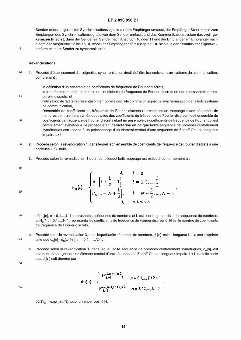
1. A method of establishing a synchronization signal for transmission in a communication system, comprising:
defining a set of discrete Fourier frequency coefficients,transforming said set of discrete Fourier frequency coefficients into a discrete time representation, andusing said discrete time representation as said synchronization signal in said communication system,wherein the set of discrete Fourier frequency coefficients represents a mapping of a centrally symmetric numbersequence onto discrete Fourier frequency coefficients, said set of discrete Fourier frequency coefficients is aset of Fourier frequency coefficients that is centrally symmetric, the method characterized in that said centrallysymmetric number sequence corresponds to puncturing a central element of a Zadoff-Chu sequence of oddlength L+1.
2. The method according to claim 1, wherein said set of discrete Fourier frequency coefficients has a DC-carrier beingzero.
3. The method according to claim 1 or 2, wherein said mapping is performed in accordance with:
where, du[n], n=0,1,..., L-1, represents the number sequence and L is a length of said number sequence, and Hu[l],l=0,1,..., N-1, represents the discrete Fourier frequency coefficients and N is the number of discrete Fourier frequencycoefficients.
4. The method according to claim 3, wherein said number sequence, du[n], is of length L and has a property such thatdu[n]= du[L-1-n], n=0,1,...,L/2-1.
5. The method according to claim 1, wherein said centrally symmetric number sequence, du[n], is obtained by puncturinga central element of a Zadoff-Chu sequence of odd length L+1, so that du[n] is given by
where WN=exp(-j2π/N), for positive integer N.
6. The method according to claim 1 or 5, wherein the centrally symmetric number sequence is a punctured Zadoff-Chu sequence of either of three root indices, u, u=u1, u=u2 or u=u3.
7. The method according to claim 6, wherein for a first root index u1, a second root index is L+1-u1.
8. The method according to claim 6 or 7, wherein each of the root indices corresponds to a cell-specific synchronizationsequence in a cellular communication system.
9. The method according to one of the claims 1 to 8, wherein the set of discrete Fourier frequency coefficients are

EP 2 090 050 B1
12
5
10
15
20
25
30
35
40
45
50
55
transformed into a discrete time representation, su[k], corresponding to
for Fourier frequency coefficients Hu[l], l=0, 1,...,N-1, where N is the number of discrete Fourier frequency coefficientsof the set.
10. A transmitter (61) for a communication system, said transmitter comprising circuitry for sending in said communicationsystem a synchronization signal as established, the transmitter being characterized by a microprocessor beingadapted to establish the synchronization signal for transmission representinga set of discrete Fourier frequency coefficients as defined,said set of discrete Fourier frequency coefficients being transformed into a discrete time representation,the set of discrete Fourier frequency coefficients being defined to represent mapping of a centrally symmetric numbersequence onto discrete Fourier frequency coefficients, said set of discrete Fourier frequency coefficients is a set ofFourier frequency coefficients that is centrally symmetric, and said centrally symmetric number sequence corre-sponds to puncturing a central element of a Zadoff-Chu sequence of odd length L+1, andsaid circuitry for sending being arranged for sending a synchronization signal corresponding to said discrete timerepresentation in said communication system.
11. The transmitter according to claim 10 characterized by the microprocessor being adapted to establish a synchro-nization signal of the method in any of claims 1 to 9.
12. A receiver (65) for a communication system, said receiver comprising circuitry for receiving in said communicationsystem a synchronization signal as established, the receiver being characterized by a microprocessor being adapt-ed to synchronize the receiver to the synchronization signal representinga set of discrete Fourier frequency coefficients as defined,said set of discrete Fourier frequency coefficients being transformed into a discrete time representation,the set of discrete Fourier frequency coefficients being defined to represent mapping of a centrally symmetric numbersequence onto discrete Fourier frequency coefficients, said set of discrete Fourier frequency coefficients is a set ofFourier frequency coefficients that is centrally symmetric, and said centrally symmetric number sequence corre-sponds to puncturing a central element of a Zadoff-Chu sequence of odd length L+1, andsaid circuitry for receiving being arranged for receiving a synchronization signal corresponding to said discrete timerepresentation in said communication system.
13. The receiver according to claim 12, characterized by the receiver corresponding to a matched filter type receiver,wherein the number of filter coefficients reduced by one corresponds to half the length of the centrally symmetricnumber sequence.
14. The receiver according to claim 13, characterized by the receiver corresponding to a matched filter type receiver,for which filter coefficients correspond to one of a plurality of root indices of a Zadoff-Chu sequence, being arrangedfor storing filter coefficients for the plurality of root indices.
15. The receiver according to claim 12, characterized by the receiver being of matched filter type.
16. The receiver according to one of the claims 12 to 15 characterized by microprocessor being adapted to a synchro-nization signal as established in the method in any of claims 1 to 9.
17. A communication system including a transmitter (61) and a receiver (65), the transmitter comprising circuitry forsending a synchronization signal as established to the receiver, the receiver comprising circuitry for receiving thesynchronization signal from the transmitter, the communication system characterized by the transmitter being atransmitter of claim 10 or 11 and the receiver being a receiver in any of claims 12 to 16, the receiver being adaptedto synchronize to the transmitter from the knowledge of the signal waveform.

EP 2 090 050 B1
13
5
10
15
20
25
30
35
40
45
50
55
Patentansprüche
1. Verfahren zum Herstellen eines Synchronisationssignals zur Übertragung in einem Kommunikationssystem, mitden folgenden Schritten:
Definieren einer Menge von diskreten Fourier-Frequenzkoeffizienten,Transformieren der Menge von diskreten Fourier-Frequenzkoeffizienten in eine zeitdiskrete Darstellung undVerwenden der zeitdiskreten Darstellung als das Synchronisationssignal in dem Kommunikationssystem,wobei die Menge von diskreten Fourier-Frequenzkoeffizienten eine Abbildung einer zentralsymmetrischen Zah-lensequenz auf diskrete Fourier-Frequenzkoeffizienten darstellt, die Menge von diskreten Fourier-Frequenz-koeffizienten eine Menge von Fourier-Frequenzkoeffizienten ist, die zentralsymmetrisch ist, wobei das Verfahrendadurch gekennzeichnet ist, dass die zentralsymmetrische Zahlensequenz dem Punktieren eines Zentral-elements einer Zadoff-Chu-Sequenz ungerader Länge L + 1 entspricht.
2. Verfahren nach Anspruch 1, wobei die Menge von diskreten Fourier-Frequenzkoeffizienten einen DC-Träger auf-weist, der null ist.
3. Verfahren nach Anspruch 1 oder 2, wobei die Abbildung folgendermaßen durchgeführt wird:
wobei du[n], n=0, 1, ..., L-1 die Zahlensequenz darstellt und L eine Länge der Zahlensequenz ist und Hu[l], l=0, 1, ...,N-1 die diskreten Fourier-Frequenzkoeffizienten darstellt und N die Anzahl von diskreten Fourier-Frequenzkoeffi-zienten ist.
4. Verfahren nach Anspruch 3, wobei die Zahlensequenz du[n] die Länge L aufweist und eine Eigenschaft dergestaltaufweist, dass du[n]=du[L-1-n], n=0, 1, ..., L/2-1 ist.
5. Verfahren nach Anspruch 1, wobei die zentralsymmetrische Zahlensequenz du[n] durch Punktieren eines Zentral-elements einer Zadoff-Chu-Sequenz ungerader Länge L+1 erhalten wird, dergestalt, dass du[n] durch
gegeben wird, mit WN=exp(-j2π/N) für eine positive ganze Zahl N.
6. Verfahren nach Anspruch 1 oder 5, wobei die zentralsymmetrische Zahlensequenz eine punktierte Zadoff-Chu-Sequenz eines von drei Wurzelindizes u, u=u1, u=u2 oder u=u3 ist.
7. Verfahren nach Anspruch 6, wobei für einen ersten Wurzelindex u1 ein zweiter Wurzelindex L+1-u1 ist.

EP 2 090 050 B1
14
5
10
15
20
25
30
35
40
45
50
55
8. Verfahren nach Anspruch 6 oder 7, wobei jeder der Wurzelindizes einer zellenspezifischen Synchronisationssequenzin einem zellularen Kommunikationssystem entspricht.
9. Verfahren nach einem der Ansprüche 1 bis 8, wobei die Menge von diskreten Fourier-Frequenzkoeffizienten ent-sprechend Folgendem in eine zeitdiskrete Darstellung su[k] transformiert wird:
für Fourier-Frequenzkoeffizienten Hu[l], l=0, 1, ..., N-1, wobei N die Anzahl der diskreten Fourier-Frequenzkoeffizi-enten der Menge ist.
10. Sender (61) für ein Kommunikationssystem, wobei der Sender Schaltkreise zum Senden eines hergestellten Syn-chronisationssignals in dem Kommunikationssystem umfasst, wobei der Sender durch einen Mikroprozessor ge-kennzeichnet ist, der dafür ausgelegt ist, das Synchronisationssignal zur Übertragung herzustellen, das eine Mengevon definierten diskreten Fourier-Frequenzkoeffizienten darstellt,wobei die Menge von diskreten Fourier-Frequenzkoeffizienten in eine zeitdiskrete Darstellung transformiert wird,wobei die Menge von diskreten Fourier-Frequenzkoeffizienten definiert wird, um eine Abbildung einer zentralsym-metrischen Zahlensequenz auf diskrete Fourier-Frequenzkoeffizienten darzustellen, die Menge von diskreten Fou-rier-Frequenzkoeffizienten eine Menge von Fourier-Frequenzkoeffizienten ist, die zentralsymmetrisch ist, und diezentralsymmetrische Zahlensequenz dem Punktieren eines Zentralelements einer Zadoff-Chu-Sequenz ungeraderLänge L+1 entspricht und die Schaltkreise zum Senden dafür ausgelegt sind, ein Synchronisationssignal, das derzeitdiskreten Darstellung entspricht, in dem Kommunikationssystem zu senden.
11. Sender nach Anspruch 10, dadurch gekennzeichnet, dass der Mikroprozessor dafür ausgelegt ist, ein Synchro-nisationssignal des Verfahrens nach einem der Ansprüche 1 bis 9 herzustellen.
12. Empfänger (65) für ein Kommunikationssystem, wobei der Empfänger Schaltkreise zum Empfangen eines herge-stellten Synchronisationssignals in dem Kommunikationssystem umfasst, wobei der Empfänger durch einen Mikro-prozessor gekennzeichnet ist, der dafür ausgelegt ist, den Empfänger mit dem Synchronisationssignal zu syn-chronisieren, das eine Menge von definierten diskreten Fourier-Frequenzkoeffizienten darstellt,wobei die Menge von diskreten Fourier-Frequenzkoeffizienten in eine zeitdiskrete Darstellung transformiert wird,die Menge von diskreten Fourier-Frequenzkoeffizienten definiert wird, um eine Abbildung einer zentralsymmetri-schen Zahlensequenz auf diskrete Fourier-Frequenzkoeffizienten darzustellen, die Menge von diskreten Fourier-Frequenzkoeffizienten eine Menge von Fourier-Frequenzkoeffizienten ist, die zentralsymmetrisch ist, und die zen-tralsymmetrische Zahlensequenz dem Punktieren eines Zentralelements einer Zadoff-Chu-Sequenz ungerader Län-ge L+1 entspricht unddie Schaltkreise zum Empfangen dafür ausgelegt sind, ein Synchronisationssignal, das der zeitdiskreten Darstellungentspricht, in dem Kommunikationssystem zu empfangen.
13. Empfänger nach Anspruch 12, dadurch gekennzeichnet, dass der Empfänger einem Empfänger des Optimalfil-tertyps entspricht, wobei die Anzahl der Filterkoeffizienten vermindert um 1 der Hälfte der Länge der zentralsym-metrischen Zahlensequenz entspricht.
14. Empfänger nach Anspruch 13, dadurch gekennzeichnet, dass der Empfänger einem Empfänger des Optimalfil-tertyps entspricht, für den Filterkoeffizienten einem von mehreren Wurzelindizes einer Zadoff-Chu-Sequenz ent-sprechen, der dafür ausgelegt ist, Filterkoeffizienten für die mehreren Wurzelindizes zu speichern.
15. Empfänger nach Anspruch 12, dadurch gekennzeichnet, dass der Empfänger vom Optimalfiltertyp ist.
16. Empfänger nach einem der Ansprüche 12 bis 15, dadurch gekennzeichnet, dass der Mikroprozessor auf einSynchronisationssignal wie in dem Verfahren nach einem der Ansprüche 1 bis 9 hergestellt ausgelegt ist.
17. Kommunikationssystem mit einem Sender (61) und einem Empfänger (65), wobei der Sender Schaltkreise zum
EP 2 090 050 B1
15
5
10
15
20
25
30
35
40
45
50
55
Senden eines hergestellten Synchronisationssignals zu dem Empfänger umfasst, der Empfänger Schaltkreise zumEmpfangen des Synchronisationssignals von dem Sender umfasst und das Kommunikationssystem dadurch ge-kennzeichnet ist, dass der Sender ein Sender nach Anspruch 10 oder 11 und der Empfänger ein Empfänger nacheinem der Ansprüche 12 bis 16 ist, wobei der Empfänger dafür ausgelegt ist, sich aus der Kenntnis der Signalwel-lenform mit dem Sender zu synchronisieren.
Revendications
1. Procédé d’établissement d’un signal de synchronisation destiné à être transmis dans un système de communication,comprenant :
la définition d’un ensemble de coefficients de fréquence de Fourier discrets,la transformation dudit ensemble de coefficients de fréquence de Fourier discrets en une représentation tem-porelle discrète, etl’utilisation de ladite représentation temporelle discrète comme dit signal de synchronisation dans ledit systèmede communication,l’ensemble de coefficients de fréquence de Fourier discrets représentant un mappage d’une séquence denombres centralement symétriques avec des coefficients de fréquence de Fourier discrets, ledit ensemble decoefficients de fréquence de Fourier discrets étant un ensemble de coefficients de fréquence de Fourier qui estcentralement symétrique, le procédé étant caractérisé en ce que ladite séquence de nombres centralementsymétriques correspond à un poinçonnage d’un élément central d’une séquence de Zadoff-Chu de longueurimpaire L+1.
2. Procédé selon la revendication 1, dans lequel ledit ensemble de coefficients de fréquence de Fourier discrets a uneporteuse C.C. nulle.
3. Procédé selon la revendication 1 ou 2, dans lequel ledit mappage est exécuté conformément à :
où du[n], n = 0,1,...,L-1, représente la séquence de nombres et L est une longueur de ladite séquence de nombres,et Hu[l], l = 0,1,...,N-1, représente les coefficients de fréquence de Fourier discrets et N est le nombre de coefficientsde fréquence de Fourier discrets.
4. Procédé selon la revendication 3, dans lequel ladite séquence de nombres, du[n], est de longueur L et a une propriétételle que du[n]= du[L-1-n], n = 0,1,...,L/2-1.
5. Procédé selon la revendication 1, dans lequel ladite séquence de nombres centralement symétriques, du[n], estobtenue en poinçonnant un élément central d’une séquence de Zadoff-Chu de longueur impaire L+1, de telle sorteque du[n] soit donnée par
où WN = exp(-j2π/N), pour un entier positif N.

EP 2 090 050 B1
16
5
10
15
20
25
30
35
40
45
50
55
6. Procédé selon la revendication 1 ou 5, dans lequel la séquence de nombres centralement symétriques est uneséquence de Zadoff-Chu poinçonnée de trois indices racines, u, u = u1, u = u2 ou u = u3.
7. Procédé selon la revendication 6, dans lequel pour un premier indice racine, u1, un deuxième indice racine est L+1- u1.
8. Procédé selon la revendication 6 ou 7, dans lequel chacun des indices racines correspond à une séquence desynchronisation spécifique à la cellule dans un système de communication cellulaire.
9. Procédé selon l’une quelconque des revendications 1 à 8, dans lequel l’ensemble de coefficients de fréquence deFourier discrets est transformé en une représentation temporelle discrète, su [k], correspondant à
pour les coefficients de fréquence de Fourier Hu [l], l = 0, 1,...,N-1, où N est le nombre de coefficients de fréquencede Fourier discrets de l’ensemble.
10. Emetteur (61) d’un système de communication, ledit émetteur comprenant des circuits pour envoyer dans leditsystème de communication un signal de synchronisation tel que établi, l’émetteur étant caractérisé par un micro-processeur étant adapté pour établir le signal de synchronisation destiné à être transmis représentantun ensemble de coefficients de fréquence de Fourier discrets tel que défini,ledit ensemble de coefficients de fréquence de Fourier discrets étant transformé en une représentation temporellediscrète,l’ensemble de coefficients de fréquence de Fourier discrets étant défini pour représenter un mappage d’une séquencede nombres centralement symétriques avec des coefficients de fréquence de Fourier discrets, ledit ensemble decoefficients de fréquence de Fourier discrets est un ensemble de coefficients de fréquence de Fourier qui estcentralement symétrique, et ladite séquence de nombres centralement symétriques correspond à un poinçonnaged’un élément central d’une séquence de Zadoff-Chu de longueur impaire L+1, etlesdits circuits d’envoi étant agencés pour envoyer un signal de synchronisation correspondant à ladite représentationtemporelle discrète dans ledit système de communication.
11. Emetteur selon la revendication 10, caractérisé par le microprocesseur étant adapté pour établir un signal desynchronisation du procédé selon l’une quelconque des revendications 1 à 9.
12. Récepteur (65) d’un système de communication, ledit récepteur comprenant des circuits pour recevoir dans leditsystème de communication un signal de synchronisation tel que établi, le récepteur étant caractérisé par unmicroprocesseur étant adapté pour synchroniser le récepteur avec le signal de synchronisation représentantun ensemble de coefficients de fréquence de Fourier discrets tel que défini,ledit ensemble de coefficients de fréquence de Fourier discrets étant transformé en une représentation temporellediscrète,l’ensemble de coefficients de fréquence de Fourier discrets étant défini pour représenter un mappage d’une séquencede nombres centralement symétriques avec des coefficients de fréquence de Fourier discrets, ledit ensemble decoefficients de fréquence de Fourier discrets est un ensemble de coefficients de fréquence de Fourier qui estcentralement symétrique, et ladite séquence de nombres centralement symétriques correspond à un poinçonnaged’un élément central d’une séquence de Zadoff-Chu de longueur impaire L+1, etlesdits circuits de réception étant agencés pour recevoir un signal de synchronisation correspondant à ladite repré-sentation temporelle discrète dans ledit système de communication.
13. Récepteur selon la revendication 12, caractérisé par le récepteur correspondant à un récepteur du type à filtreadapté, dans lequel le nombre de coefficients de filtre réduit de un correspond à la moitié de la longueur de laséquence de nombres centralement symétriques.
14. Récepteur selon la revendication 13, caractérisé par le récepteur correspondant à un récepteur du type à filtreadapté, pour lequel les coefficients de filtre correspondent à l’un d’une pluralité d’indices racines d’une séquencede Zadoff-Chu, étant agencé pour mémoriser les coefficients de filtre de la pluralité d’indices racines.

EP 2 090 050 B1
17
5
10
15
20
25
30
35
40
45
50
55
15. Récepteur selon la revendication 12, caractérisé par le récepteur étant du type à filtre adapté.
16. Récepteur selon l’une quelconque des revendications 12 à 15, caractérisé par le microprocesseur étant adapté àun signal de synchronisation tel que établi dans le procédé selon l’une quelconque des revendications 1 à 9.
17. Système de communication comportant un émetteur (61) et un récepteur (65), l’émetteur comprenant des circuitspour envoyer au récepteur un signal de synchronisation tel que établi, le récepteur comprenant des circuits pourrecevoir le signal de synchronisation de l’émetteur, le système de communication étant caractérisé par le fait quel’émetteur est un émetteur selon la revendication 10 ou 11, et le récepteur est un récepteur selon l’une quelconquedes revendications 12 à 16, le récepteur étant adapté pour se synchroniser sur l’émetteur en connaissant la formed’onde du signal.
EP 2 090 050 B1
18

EP 2 090 050 B1
19
EP 2 090 050 B1
20

EP 2 090 050 B1
21

EP 2 090 050 B1
22

EP 2 090 050 B1
23
REFERENCES CITED IN THE DESCRIPTION
This list of references cited by the applicant is for the reader’s convenience only. It does not form part of the Europeanpatent document. Even though great care has been taken in compiling the references, errors or omissions cannot beexcluded and the EPO disclaims all liability in this regard.
Patent documents cited in the description
• SE 0701056 [0001]