Method and apparatus for round-trip software engineering
22
US 20020170048A1 (12) Patent Application Publication (10) Pub. No.: US 2002/0170048 A1 (19) United States ZGARBA et al. (43) Pub. Date: NOV. 14, 2002 (54) METHOD AND APPARATUS FOR ROUND-TRIP SOFTWARE ENGINEERING (76) Inventors: TONY ZGARBA, HOUSTON, TX (US); HELGA YANG, PAOLI, PA (US); DILHAR DESILVA, HOUSTON, TX (US) Correspondence Address: RICHARD F JAWORSKI, COOPER& & DUNHAM LLP 1185 AVENUE OF THE AMERICAS NEW YORK, NY 10036 (US) ( * ) Notice: This is a publication of a continued pros ecution application (CPA) ?led under 37 CFR 1.53(d). (21) Appl. No.: 09/190,761 Publication Classi?cation (51) Im. c1? . .... .. G06F 9/44 (52) Us. 01. ............................................................ ..717/168 (57) ABSTRACT A method of round-trip engineering source code from a softWare model, and in particular a method of forWard engineering code previously reverse engineered into a soft Ware model Whereby to generate updated source code With out any changes to the code not changed in the model, and Without using obtrusive code markers in the source code. Elements from the original source code represented by the model are placed in a meta-model, and compared to a similar meta-model of the softWare model. Appropriate changes and additions are made in the source code to elements Which have been changed in the softWare model. The rest of the (22) Filed: Nov. 12, 1998 code in the softWare model remains untouched. 2 / 6 / / 4 2 x DIAGRAMMATIC REPRESENTATION SOFTWARE MODEL SOURCE CODE \ K
-
Upload
vuongthien -
Category
Documents
-
view
226 -
download
4
Transcript of Method and apparatus for round-trip software engineering

US 20020170048A1
(12) Patent Application Publication (10) Pub. No.: US 2002/0170048 A1 (19) United States
ZGARBA et al. (43) Pub. Date: NOV. 14, 2002
(54) METHOD AND APPARATUS FOR ROUND-TRIP SOFTWARE ENGINEERING
(76) Inventors: TONY ZGARBA, HOUSTON, TX (US); HELGA YANG, PAOLI, PA (US); DILHAR DESILVA, HOUSTON, TX (US)
Correspondence Address: RICHARD F JAWORSKI, COOPER& & DUNHAM LLP 1185 AVENUE OF THE AMERICAS NEW YORK, NY 10036 (US)
( * ) Notice: This is a publication of a continued pros ecution application (CPA) ?led under 37 CFR 1.53(d).
(21) Appl. No.: 09/190,761
Publication Classi?cation
(51) Im. c1? . .... .. G06F 9/44
(52) Us. 01. ............................................................ ..717/168
(57) ABSTRACT
A method of round-trip engineering source code from a softWare model, and in particular a method of forWard engineering code previously reverse engineered into a soft Ware model Whereby to generate updated source code With out any changes to the code not changed in the model, and Without using obtrusive code markers in the source code. Elements from the original source code represented by the model are placed in a meta-model, and compared to a similar meta-model of the softWare model. Appropriate changes and additions are made in the source code to elements Which have been changed in the softWare model. The rest of the
(22) Filed: Nov. 12, 1998 code in the softWare model remains untouched.
2
/ 6 / / 4 2 x
DIAGRAMMATIC REPRESENTATION SOFTWARE MODEL SOURCE CODE
\ K

Patent Application Publication Nov. 14, 2002 Sheet 1 0f 14
6
/
FIG1
DIAGRAMMATIC REPRESENTATION
&
US 2002/0170048 A1
2
/ / 4 \
SOFTWARE MODEL SOURCE CODE
/
FIG 2


Patent Application Publication Nov. 14, 2002 Sheet 3 0f 14
20
FIG 4
SOFTWARE MODEL
SOURCE CODE
N EWLY GENERATED SOURCE CODE
US 2002/0170048 A1
80

Patent Application Publication Nov. 14, 2002 Sheet 4 0f 14
1O
15
20
FIG 5
/* This is a library file */
class X {
int att'l; Z att2; void doThis();
/*imp0rtant comment about Class Y*/
class Y {
int att3; void doTheOtherO
}
US 2002/0170048 A1
(DOOMODU'i-b-OONA

Patent Application Publication Nov. 14, 2002 Sheet 5 0f 14 US 2002/0170048 A1
20292622? 28% > 295250? E.“ Em
N A x N?
_o_uo_>_-m6_>_ uohomcwmcm 096%: $596 w 9-"

Patent Application Publication Nov. 14, 2002 Sheet 7 0f 14 US 2002/0170048 A1
/
SLIM
“_ N 650260
WM!!! w P 65.00
I?!
i! N was m P 25.00 .. 52:22 6:30 262 QC 260 850m 655 wEmz
m=0=2u0wm< 223.350 m m N
M Ni 5.5.2.1}! < N >
Em < P X
6:30 wEmz mi @9502 a; 0262 $38.52 .3320 _mvo_>_ ohmécow 0225: w 6-“
NH

Patent Application Publication Nov. 14, 2002 Sheet 8 0f 14 US 2002/0170048 A1
Qw
ww it p \
002395
uoccmucD m?
umccmucD m?
>
2% .96 am 0:3
uocambcj w
205250? 8559.:
HE“ Em
N_A
B05695
99% .cO “a 0:3
962
Nam _
2g .96 3" 2:
99m .50
#2:
46 GE
Patent Application Publication Nov. 14, 2002 Sheet 9 0f 14 US 2002/0170048 A1
> 29???? 205250?
N A 2.56.
NEW x
$602 ohmBcow E9; 682-922 uogwmsmcm Emzzom mm 0-"

Patent Application Publication Nov. 14, 2002 Sheet 10 0f 14 US 2002/0170048 A1
mcoz v
mcoz
20292622? UQEQQ m?
mcoz m?
>
22m .96
202922?
mcoz
202C250?
ocoz
E: Em
@coz
X
mcoz N
Nam
MR 3:
99% :0 3m 2:
wuou 850w E2”, umumhwcmm EnoEémE
Om 0E

Patent Application Publication Nov. 14, 2002 Sheet 11 0f 14 US 2002/0170048 A1
FIG 10
Index FHe
/* This is a library ?le */
class X
{ int att1; Z att2; void doThis();
}
/*lmportant comment about Class Y*/
class Y
{ /* int att3; *l void doTheOther()
void doThat();

Patent Application Publication Nov. 14, 2002 Sheet 12 0f 14 US 2002/0170048 A1
FIG 11
* This is a library file *I 5
class X {
int att'l; Z att2;
10 void doThisO; void doThat();
}
/*|mportant comment about Class Y*/ 15
class Y {
/*int att3;*/ void doTheOtherO
20 }

Patent Application Publication Nov. 14, 2002 Sheet 13 0f 14 US 2002/0170048 A1
FIG 12
Exported PowerBuilder PowerBuilder
Object Object
. . Exported -
PowerBullder \ PowerBullder \ . \ PowerBullder
Object , ORCA AP‘ ’ Powerj3ullder , ORCA API —> MODEL Object
PowerBuilder Exported Object PowerBuilder
Object

MODEL
Patent Application Publication Nov. 14, 2002 Sheet 14 0f 14 US 2002/0170048 A1
FIG 13
_ PowerBuilder I
.sr* flle ORCA API ‘
A V
Exported PowerBuilder
Object
V
pb_merge.$$$ Result of merging
exported *0t_>Ject wlth + Report File .sr flle

US 2002/0170048 A1
METHOD AND APPARATUS FOR ROUND-TRIP SOFTWARE ENGINEERING
BACKGROUND OF THE INVENTION
[0001] The present invention relates to software design modeling, and in particular to roundtrip software engineer ing in Which a softWare application is reverse engineered into a softWare model, the softWare model can be changed, and the code represented by the softWare model can then be re-coded.
[0002] Due to inadequate softWare design modeling, application development projects have typically been very dif?cult to deliver With any kind of consistent success. A very loW percentage of signi?cant application development projects are completed on time and Within budget. As projects have groWn larger in scope, organiZations have begun to partition applications and corresponding sub systems into multiple tiers, With each tier being developed and maintained independently of the others. This enables applications to scale up to the enterprise level. As more complex 3rd generation language projects are developed, a corresponding need for formal analysis and design modeling has increased. Accordingly, in order to combine various disjoint applications into a single large scale solution, exist ing applications need to be visualiZed and understood, Without recourse to digging through the source code. Fur thermore, projects need to be re-engineered using compo nent-based development techniques to take advantage of various emerging object technologies such as CORBA, Microsoft ActiveX (OCX) and the World Wide Web.
[0003] The ?rst step required involves adding object oriented analysis and design to the existing development process. As softWare needs become increasingly complex, an environment is needed to complement the third genera tion lifecycle With an object-oriented analysis and design front end, enabling the application Writer to take advantage of reusable components and track the development of the project. Many modeling products have been developed for this purpose, such as Platinum Technology, Inc.’s Paradigm Plus. The challenge in such products is to keep the design information synchroniZed With the code.
[0004] As represented in FIG. 1, the capability is required to keep a softWare model 2 up to date With changing source code 4, alloWing the generation of easily understood dia grammatic representations of the softWare design. This capability has been included in most, if not all, object modeling tools. Without this feature, a softWare model must be manually updated Whenever changes are made in the design as the source code is Written. This often leads to forgotten updates to the softWare model and a softWare model that is out of date With respect to the source code that it is intended to represent.
[0005] As shoWn in the Venn Diagram in FIG. 2, the problem is exacerbated by the fact that the softWare model generally only represents a subset of the information repre sented in the source code, and a large amount of meta-data concerning the project Which is stored in the softWare model is not represented in the source code. For example, neither comments in the source code nor properties of objects relating to their formatting Will generally be incorporated in the softWare model. Design principles and relationships betWeen objects in the modeling methodology being used
Nov. 14, 2002
Which are represented in the softWare model, Will not be included explicitly in the source code.
[0006] Several tools in the industry have added a round trip engineering technology Which can read the source code and synchroniZe the softWare model With the source code. HoWever, these tools rely on being able to place markers into the source code 4 to de?ne areas of the code Which corre spond to the softWare model 2. These markers clutter the source code With extraneous marks, causing readability problems. In addition, this technique is prone to error When one of the markers is deleted or inadvertently edited by the developer. [0007] What is required is a method of round-trip engi neering alloWing a softWare model to be kept synchroniZed With corresponding source code or equivalent objects, With out the need for code markers cluttering up the code.
STATEMENT OF INVENTION
[0008] The present invention provides a system for keep ing a softWare model representing a softWare application in synchroniZation With the source code it represents Without the need for any kind of source code markers delimiting parts of the code Which are to be synchroniZed With the softWare model. The code in the softWare application is analyZed, and a softWare model of the aspects of the application Which can be incorporated in the softWare model is generated. The softWare model is then used to regenerate the source code represented by the softWare model, and any of the source code Which is not represented in the softWare model is merged into the generated source code from the original code.
[0009] These and other objects of the invention Will be apparent from the remaining portion of this speci?cation.
BRIEF DESCRIPTION OF THE DRAWINGS
[0010] FIG. 1 is a diagram shoWing an overvieW of the requirements of a round-trip engineering tool.
[0011] FIG. 2 is a Venn Diagram representing the infor mation stored in the source code for a project and a softWare model of the same project.
[0012] FIG. 3A shoWs an exported PoWerBuilder object by Way of example.
[0013] FIG. 3B shoWs the PoWerBuilder object of FIG. 3B once it has been reverse engineered and forWard engi neered in accordance With bi-directional engineering tech niques knoWn prior to the present invention.
[0014] FIG. 4 shoWs an overvieW of a round-trip engi neering process in accordance With a ?rst embodiment of the invention.
[0015] FIG. 5 shoWs sample C++ source code by Way of example. [0016] FIG. 6 shoWs a meta-model generated from the source code shoWn in FIG. 5.
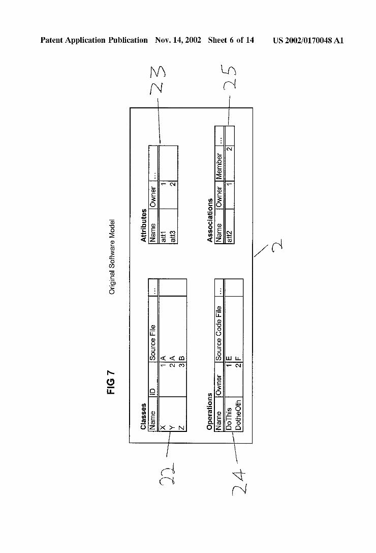
[0017] FIG. 7 shoWs tables in a database representing a softWare model. FIG. 8 shoWs modi?ed tables in a database representing a softWare model.
[0018] FIG. 9A shoWs a meta-model generated from the for source code shoWn in FIG. 5.

US 2002/0170048 A1
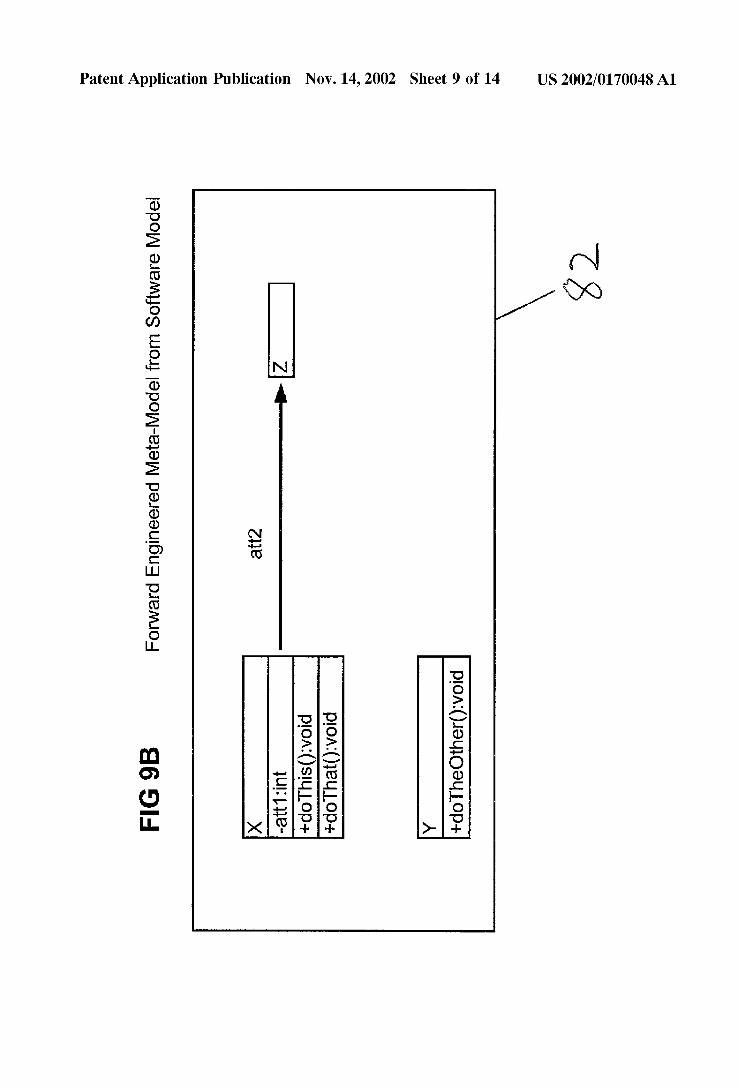
[0019] FIG. 9B shows a meta-model generated from the software model shown in FIG. 8.
[0020] FIG. 9C shows an updated meta-model based on the meta-models in FIGS. 9A and 9B.
[0021] FIG. 10 showing preliminary merge code
[0022] FIG. 11 showing ?nal merge code
[0023] FIG. 12 showing overview of reverse engineering (PowerBuilder) [0024] FIG. 13 showing overview of forward engineering
DETAILED DESCRIPTION
[0025] As shown in FIG. 1, the embodiment of the invention hereinafter described relates to round-trip engi neering of a software project between a software model 2 and the project source code 4, whereby the software model and the software can be kept synchroniZed.
[0026] The primary example used to clarify the operation of the embodiment and represented in FIGS. 5-11 Is based around the C++ programming language, although there is no reason the invention could not operate on other object oriented languages or other types of languages, as will become apparent. Languages in which the objects are nor mally stored in proprietary binary formats can often be exported into ?at ?le formats, such as ASCII Text Files with representations of all the features of the objects, so that the objects can be re-imported back into the application. Examples of such applications are Microsoft’s Visual BASIC, Visual C ++, Access and Sybase PowerBuilder. Often, certain modules in these applications will be stored as ?at source code ?les anyway, such a s C++ .cpp ?les and BASIC .bas ?les.
[0027] The software model 2 does not need to provide all the concepts of the language of the source code, and will normally provide modeling for the higher level concepts in the source code such as classes, attributes, operation/meth ods etc., or data How modeling between components. Many aspects of the source code, such as formatting of objects therein will often not be stored in the software model, but it is very important that such information is not lost in round trip engineering. For example, code exported from a Sybase PowerBuilder application shown in FIG. 3A includes infor mation concerning the width, height and position of a window type class w_sort. Such information generally would not be included in a software model. If this code were reverse engineered into a software model 2, and then rec reating using the software model per se, the code generated might have the appearance of the code shown in FIG. 3B with much of the formatting information being lost in the round-trip.
[0028] Furthermore, the language in which the software model 2 is generated will ideally be able to model various software development languages and therefore it is unlikely that any particular language being modeled will support all the concepts supported by the modeling language.
[0029] Accordingly, a situation exempli?ed by the Venn Diagram in FIG. 2 arises, with the software model and the software development language sharing common concepts, but each having concepts not provided by the other.
Nov. 14, 2002
[0030] For example, if the source code language were C++, the software model might provide for the modeling of C++ classes, structs, unions and enumeration classes with similar structures, although enumeration classes might be considered as a data type rather than a class in the software model. C++ attributes could be mapped onto software model attributes, associations and/or aggregations depending on options passed to the reverse engineering utility and code situations. Additional information, such as “static” or “const” might be marked in the operations’ properties accordingly. Global methods might be mapped to global operations in the modeling language. C++ methods might be modeled as operations in the modeling language, and over loaded methods could be given an integer ID concatenated to their name to uniquely identify them in the software model.
[0031] Many software modeling products, such as Plati num Technology, Inc.’s Paradigm Plus are currently avail able which permit generation of software models from source code using various different modeling methodolo gies, and also permit the generation of source code from the software model. The following description of the operation of the invention assumes that the necessary functionality is already in place to generate such software models and regenerate source code from these software models and accordingly does not address the actual representation of the software model, except by way of example. [0032] The source code 4 of a software project, which will generally consist of a set of ?les stored on a computer or a network or computers. The present invention provides a method for round-trip engineering of source code using an implementing an improved system for forward engineering.
[0033] As stated above, standard techniques are used to generate a software model, or to augment a software model 2 already generated. The software model can then be for ward engineered to generate source code for the project as shown. Importantly, when a software project is reverse engineered from source code, and the software model gen erated is forward engineered, the resultant code should be essentially the same, regardless of what information in the source code is represented in the software model. This allows for proper “round-trip” engineering of the software project, so that the software model and the source code can be kept synchroniZed, updates in both the source code and the software model will be maintained when generating the source code from the software model and vice versa, and comments and other features of the source code not repre sented in the software model do not get moved around or even disappear in the round-trip process.
[0034] The operation of the round-trip engineering of the speci?c embodiment of the invention described is shown in broad terms in FIG. 4.
[0035] Reverse engineering 10 is carried out in a normal manner, but importantly, during forward engineering 12, the existing source code 4 is merged with the data from the software model 2 whereby to generate new source code 8 which then replaces the existing source code. Corresponding sections of the source code are identi?ed for each element in the software model 2, and any changes, additions or dele tions that have been made in the software model and which do not correspond to the source code are incorporated in the new source code 8, without affecting any parts of the source code not represented by the software model.
US 2002/0170048 A1
[0036] The operation of the speci?c embodiment of the invention is hereinafter described With reference to FIGS. 5-11. The invention relates to forWard, reverse and round trip engineering from any softWare language to a softWare model representing the softWare. An example of the opera tion of the embodiment is given With reference to the C++ programming language, although the embodiment is equally applicable to other programming language, and ideally Would be able to handle multiple programming languages. The invention is in no Way limited to the constructs used by the C++ programming language. The invention primarily relates to the merging of the source code and the data in the softWare model, Where possible retaining the original source code Without recourse to markers in the code. The actual contents of the code are not relevant to the invention.
[0037] Source code 4 in source code ?les 40, Written in a particular programming language are reverse engineered into a neW softWare model 2 or incorporated into an existing softWare model 2, and then forWard engineered from the softWare model 2 into a neW set of source code ?les 80, or merged With existing source code ?les 40 Without recourse to neW source code ?les.
Reverse Engineering
[0038] Reverse engineering according to this embodiment is effected by parsing the code and transforming all the elements of the code Which can be represented by the softWare model into a generic meta-model, for example using the CASE Data Interchange Format (CDIF) Which is commonly used as a generic standard representation format for softWare entities. Details of the CDIF set of standards can be obtained from the Electronic Industries Association CDIF Technical Committee. From the generic meta-model, the elements of the code Which can be represented in the softWare model selected are exported into the softWare model. The method of exporting the data from the meta model to the softWare model Will depend on the format of the softWare model and meta-model generated, but in most cases Will simply involve populating a database 30 of elements. The softWare model 2 of this embodiment of the invention uses a database comprising tables 22, 23, 24, 25 to represent the data.
[0039] The softWare model 2 need not be in database format, and might be stored in any kind of data structure. In the database shoWn in FIG. 7, different elements of the application are classi?ed by type into tables 22, 23, 24, 25 With appropriate ?elds to represent all the properties of the elements, and cross reference them to other associated elements appropriately. The format of these tables Will vary depending primarily on the methodology embodied by the softWare model to represent the softWare being modeled. For example, the softWare model shoWn in FIG. 7 represents classes, attributes, operations, associations, the relationships therebetWeen and other features thereof. These constructs can be used to represent constructs in many object oriented languages. For example, C++ methods can be represented as operations in the softWare model, and C++ constructs of the types CLASS, STRUCT, UNION and ENUM can all be represented as classes in the softWare model. The softWare model might also hold information relating to other softWare entities such as objects or data How betWeen entities. Four tables are shoWn in FIG. 7, each holding information relating to classes, attributes, operations and associations.
Nov. 14, 2002
The tWo classes X and Y in the Classes table 22 are given integer identi?ers Which the softWare model uses to identify them. Other features of the classes are also stored in the table, such as the source ?le of the class in question, and the type of the class in question, such as CLASS or STRUCT. Certain of the ?elds provided by the softWare model for each of the classes might be inapplicable to the softWare language being modeled, and can be left empty.
[0040] Each entry in the attributes table 23 has a ?eld representing the name of the attribute, and the oWning class. Other ?elds might be the scope of the attribute, the type, and the source ?le. As attributes might be overloaded, ie. dif ferent attributes in different classes sharing the same name, the name given to the attribute in the softWare model might need to be modi?ed to distinguish betWeen commonly named attributes and an alias given for the attribute in question. [0041] Alternatively, attributes could be given arbitrary identi?ers as key values in the table, so that more than one attribute could share the same name. The same principle Would be used for other constructs Which could be over loaded, such as operations.
[0042] Records in the operations table 24 contains opera tions, Which in this example Would hold C++ methods and functions. These records likeWise have ?elds for the oWning class, if there is one. In this example based around C++, a source ?le ?eld in this table Would refer to the actual ?le containing the source code for the method, rather than the source ?le containing the declaration of the method, as the latter could be derived from the source ?le of the owning class.
[0043] Finally, the associations table 25 contains associa tions betWeen classes. In this example, attributes Which are of a class type are stored as associations, although they could be stored in the attributes table With the type set to the class name. The oWning class ?eld stores the class in Which the attribute is de?ned, and via Which it is accessed. The member class stores the class of Which the attribute is a type, that is to say, the class type of the attribute.
[0044] Reverse engineering of object based languages, rather than source code can be achieved by exporting all the information encapsulated in the objects into a ?at ?le format, for example ASCII, and then importing any information Which can be represented by the softWare model 2 from the exported ?le into the CDIF meta-model and from there imported into the softWare model. The step of representing the data in the CDIF format could be avoided. HoWever, using the intermediate step of generating a CDIF format ?le has the advantage that standard utilities Which are already in existence for transforming data from various source lan guages into CDIF Format can be used, and a single utility can then be used to import the data from CDIF format into the softWare model. If the softWare model Were to be generated directly from the source code, a different utility Would need to be generated for each source language supported by any particular softWare model format. FIG. 12 shoWs a an example of the operation of reverse engineering according to the invention on a set of PoWerBuilder objects. If the invention Were operating on C++ source code, the exporting step Would not be necessary, and the code could be transformed directly into CDIF Format.
[0045] If a softWare model 2 is already present When the data from the source ?le is imported into the softWare model,

US 2002/0170048 A1
and data from the source ?le is to be merged into the software model rather than replacing it, a check is made before adding elements into the database for corresponding elements already in the database. If a corresponding element is not found, the element is simply added to the database.
[0046] If a corresponding element is found in the database and the data ?elds Which are de?ned in both the element to be merged and the corresponding element already in the table match, any data ?elds de?ned only in the element being imported are incorporated in the existing ?elds for the corresponding elements and the other ?elds are left untouched.
[0047] If a corresponding element is found in the database and the data ?elds Which are de?ned in both the element to be merged and the corresponding element already in the table do not match, contention handling is used to ascertain Whether the imported element or the element already in existence Will have priority. For example, a message box could be displayed reporting the contention and asking Which data should be used in the softWare model. Which of the imported data and the data already present has priority could also be preset before the import commences so that n o contention resolution is necessary.
[0048] Furthermore, a check could also be made that all the data in the softWare model associated With the source ?le or source ?les being imported Were actually among the elements imported. Any mismatch Would correspond either to elements added to the softWare model or elements removed from the source code since the softWare model and the source code Were last synchroniZed. If logging of addi tions to the softWare model are made, a simple check of the logged additions Would alloW the importing utility to ascer tain Whether the element had been added to the softWare model or removed from the source code and take appropriate action. In the latter case, a message box could be provided asking if the element should be removed from the softWare model.
ForWard Engineering
[0049] ForWard engineering is effected by merging the data in the softWare model 2 With any existing source code 4, adding neW code, changing code or removing code When necessary to create neW source code 8. Importantly, existing source code not affected by changes in the softWare model is left unchanged. An example of the forWard engineering process Which could be used to generate a PoWerBuilder project, after reverse engineering in accordance With FIG. 12, is shoWn in FIG. 13. The ForWard Engineering process Will generally be used to modify source code based on modi?cations to the softWare model, or to create neW source code. The present invention provides a system for doing the former, and the process is explained With reference to FIGS. 8 to 11 Wherein FIG. 8 shoWs a softWare model 2 being a modi?ed version of the softWare model shoWn in FIG. 7.
[0050] As mentioned already, ?elds in the softWare model 2 might not be transferrable into the source code. For example, a ?eld might be provided in the representation of a class in the softWare model identifying a document con taining an explanation of the function of the class in ques tion. Such ?elds can be populated in the softWare model to aid in the softWare design Without being incorporated into the source code, and, as discussed above, Will not be affected
Nov. 14, 2002
by reverse engineering of the source code because corre sponding data Which might cause a contention Would never be imported from the source code.
[0051] Returning to FIGS. 9A and 9B, When performing forWard engineering of a source code ?le, a generic meta model 80 of the data in the source ?le or ?les being forWard engineered, and a generic meta-model 82 of the data in the softWare model are ?rst generated. Meta-models Which might be generated from the modi?ed softWare model shoWn in FIG. 8 and the original source code shoWn in FIG. 5 are shoWn in FIGS. 9A and 9B respectively. The meta models might for example be generated in CDIF format, as discussed above With reference to the reverse engineering process. The generic meta-model format used must permit representation of all the elements of the source-code that can be represented in the softWare model and vice-versa. The use of the generic meta-model makes it possible to compare the tWo different data sources. Mappings from each speci?c environment to the generic meta-model are developed to ensure that no data is lost and the appropriate information is compared. Furthermore, only the elements from the softWare model Which should be present in the source-code ?le being forWard engineered are extracted. For example, all the classes stored in the softWare model 2 With their source-code ?le ?eld corresponding to the source-code ?le Will be brought into the meta-model 82, and all the attributes, operations and associations oWned by those classes. Classes and other objects from source-code ?les other than the source-code ?le being generated are not placed in the meta-model. For example, as shoWn in FIG. 9A, Class Z is not put in the meta-model, as it does not form part of source-code ?le A (see FIG. 8). If more than one source ?le is to be generated in the forWard engineering process, the method described for forWard engineering Will be carried out for each source ?le and the appropriate data extracted form the softWare model 2 in each case.
[0052] The operation of the meta-model generation and the nature of the meta-models generated Will depend on the structure of the programming language and the constructs therein, as Well as the constructs used in the softWare model. It must be possible to search through the elements in the source-code meta-model 80 and identify corresponding ele ments from the softWare model 2 and the source code 4. For example, different classes, variables and other independent structures in the source code such as STRUCT and UNION structures could be stored in a linked list. Elements oWned by these structures could be placed in a linked list pointed to by the appropriate element in the main linked list. Searching for elements is then easily accomplished by passing doWn the linked list, ?nding the appropriate elements, and if necessary then looking through the appended linked list associated With that element.
[0053] Importantly, each element in the generic meta model generated from the source code has associated With it a line number 84 and a “change state”86. The line number corresponds to the line number of the element in question in the original source code. In alternative embodiments of the invention, the actual start and ?nish points in the code associated With any particular element could be stored in the softWare model, rather than just the line number, so that multiple elements on one line can be independently merged.

US 2002/0170048 A1
For example, in the example meta-model generated from the source code shown in FIG. 9A, the line numbers 84 are shown in the center column.
[0054] The change state 86 is shoWn in the right column for each of the elements in FIG. 9A. It can have one of four values: Added, Deleted, Modi?ed and None. Initially, When the meta-model is generated, the elements Will all have an unde?ned change state, to represent that the merge has not yet commenced, and no changes have been made to the meta-model, as shoWn in FIG. 9A.
[0055] The meta-model 82 generated for the softWare model 2 does not require the line numbers 84 and change states 86 as Will become apparent. A representation of a meta-model generated for the softWare model 2 is shoWn in FIG. 9B.
[0056] A search is made over the generic meta-model 80 of the source code 4 for a corresponding element to each element in the meta-model 82 for the softWare model 2.
[0057] If a corresponding element is not found, the ele ment is added to the meta-model for the source code, and the element’s “ChangeState” is set to “Added”.
[0058] If the element is found but there is a parameter mismatch, the parameters are changed to the updated param eters., and the change state of the corresponding element is set to “Modi?ed”. A representation of the replaced param eters Would be stored in a ?le, or in the meta-model so that an appropriate log can be made at the end of the ForWard Engineering Process.
[0059] If the element is found, and the parameters of the element match, the change state is set to “None” to re?ect that there are no changes.
[0060] Once all the elements have been searched for, any elements that have not had their change state set must have been removed from the softWare model. These elements have their change state set to “Deleted”. The Change States of all the elements could initially be set to “Deleted” before the search instead of being left empty to avoid passing through all the elements a second time.
[0061] To avoid having to generate the second generic meta-model 82, the elements in the meta-model format generated from the softWare model 2 could instead be compared With the meta-model 80 as they are generated As each element is compared, the same actions described above Would be carried out to set the change states, resulting in the same merged meta-model.
[0062] It should be noted that it is assumed in the above processing that the softWare model is assumed to be the correct version and the source code is assumed to be out of date. HoWever, the tWo could be synchroniZed if updates to the source code and the softWare model Were previously logged, and the information in the log used to decide Which of tWo corresponding elements in the tWo meta-models had priority When the softWare model and the source code do not agree. Reverse engineering Would then have to be performed to bring the softWare model into line With the neW source code generated. This Would effectively be the opposite round-trip engineering, starting With ForWard Engineering. It is generally simpler to the round-trip engineering in the conventional order and the associated merging procedure
Nov. 14, 2002
With the softWare model having priority is therefore the procedure dealt With herein in detail.
[0063] The updated meta-model 88 resulting from this process is shoWn in FIG. 9C With the operation doThat( ) added and the attribute 3 deleted from the source-code meta-model.
[0064] A neW version of the source code ?le is then generated from the original source code ?le shoWn in FIG. 5 and the generic-meta model. The neW version could be constructed in a ?le, in a one-dimensional text array With an entry for each line of code, or by placing the source code in a linked list With one entry for each line of code. TWo essentially different approaches could be used for inserting neW lines of code into the source code. The neW source code could be added to the end, and appropriate mappings gen erated from an index, or the loWer part of the data structure in question could be shifted doWn expanded and the neW code slotted in. This Would generally be easier if the construction Was taking place in a linked list or an array. It is assumed in this example that neW code is added to the end of a ?le, and an index of positions in the ?le for each line of code updated appropriately, as shoWn in FIG. 10. The folloWing procedure is then carried out for each elements in the generic-meta model of the code:
[0065] If the change state is None, nothing is done to the associated source code.
[0066] If the change state is “Deleted”, the appropriate line is found in the neW source code ?le using the index, and the line is removed using syntax speci?c comments (i.e. com mented out). For example, in C++, this Would involve using comments /* and */ at the beginning and end of the line. Alternatively, the code could actually be removed, and the removed text could be recorded in a log ?le. In this case, the index position for the line removed Would be deleted, and all the other index locations beloW it moved up by one.
[0067] If the change state is “Added”, the appropriate place to add the neW code is established. For example, if the neW element is a member of a class, the last line in the class is found by scanning through all the elements in the class and adding 1 to the highest line number found. Alternatively, the end of the class could actually be included in the generic meta-model With the class element in question, along With the ?rst line number in the class, or a scan of the actual source code could be made to ?nd the last line in the class. A neW line or neW lines are added to the end of the source code and appropriate code for the element is entered therein. The appropriate point relative to the last line in the class in the original source code is found in the index, and references to the neW lines of code inserted. All the index entries beloW this point are moved doWn appropriately. The result of this operation inserting the method doThat( ) is shoWn in FIG. 10.
[0068] If the change state is “changed”, the appropriate index entry is found for the line, and appropriate changes made to the code.
[0069] Once all the necessary changes and additions have been made, a pass is made through the index and the corresponding lines of code from the merged source code ?le or data structure representative thereof are extracted and Written to a neW ?le in the correct order as shoWn in FIG. 11. The original source code ?le is then replaced by the neW source code ?le.