Metering Standards and Procedures Issue 11 - DOE · Metering Standards and Procedures ... Service...
218
Public WESM Market Manual Metering Standards and Procedures Issue 11.0 Abstract This document covers the development, validation, approval, publication and revision of the WESM Metering Manual. Document Identity: WESM-MSDM-MM-11 Issue: 11.0 Reason for Issue: Implementation of Preferential Dispatch Approval Date: Publication Date: Effective Date: PUBLIC Annex C
Transcript of Metering Standards and Procedures Issue 11 - DOE · Metering Standards and Procedures ... Service...

Public
WESM Market Manual
Metering Standards and Procedures Issue 11.0
Abstract This document covers the development, validation, approval, publication and revision of the WESM Metering Manual.
Document Identity: WESM-MSDM-MM-11
Issue: 11.0
Reason for Issue: Implementation of Preferential Dispatch
Approval Date:
Publication Date:
Effective Date:
PUBLIC
Annex C

Metering Standards and Procedures WESM-MSDM-MM-11 Effective Date:
Public
Document Change History
Issue No.
Proponent Date of Effectivity
Reason for Amendment
1 TWGMC 1/28/2005 New Document, Incorporate the comments of Mother Committee TWG
2 8/29/2005 (1) Changes in SEIN (2) Inclusion of Metering Point Location (3) Additional Procedures in the Meter Data
Collection/Retrieval System (4) Additional Procedures in the Validation,
Estimation, and Editing (5) Inclusion of the Metering Service Agreement
Pro-forma (6) Inclusion of Meter Security in the Metering
Installation Standard
3 Changes in Section 7.3.5 Meter Value Estimation.
4 (1) Changes in Metering Services Provider Registration under Section 4.1 Introduction and Section 4.2 Pre-requisite for Registration.
(2) Changes in Section 6.2 Meter Data Collection. (3) Inclusion of a new Section 6.9 – Emergency
Procedure. (4) Upgrade Section 7.5 – Work Flow for Metering
Data Validation, Estimation and Editing. (5) Changes made in Section 7.6 Procedural
Steps for Validation, Estimation and Editing Process.
(6) Inclusion of a new Section 9 – Site Specific Loss Adjustment (SSLA).
5 2/8/2007 Changes “Philippine Electricity Market Corportion” or “PEMC” to “Market Operator” or “MO”.
6 RCC Metering Subcommittee
8/12/2008
2/8/2010
(1) Addition of new Section 7.4.3.4 on the Use of Meter Register Reading Reading in VEE
(2) Inclusion of new Section on the Metering Service Provider (MSP) Perfomance Measurement
7 RCC Metering Subcommittee
8/12/2008 Revision of Section 9 on the allocation of transformer losses in SSLA calculation
8 RCC/PEMC 11/12/2012 Correction of Section 9.8.3 by modifying the formulae that determines SSLA in the WESM, with the value/term 1000 to be incorporated in the formulae for consistency with the units of real and reactive losses in the equations.
9 RCC/PEMC 06/20/2013 Revisions to Section 9.7 of the Metering

Metering Standards and Procedures WESM-MSDM-MM-11 Effective Date:
Public
Standards and Procedures to clarify the respective roles of the Network Service Provider, Metering Service Provider, the Market Operator as well as Trading Participants in carrying out site-specific loss adjustments.
10 RCC/PEMC 05/30/2014 Revision to Section 1.3.4 to replace ‘Dispute Resolution Administrator’ with ‘Enforcement and Compliance Officer’ as the one to undertake investigations of infractions and/or tampering of meter data and metering facilities.
11 PEMC Implementation of Preferential Dispatch

Metering Standards and Procedures WESM-MSDM-MM-11 Effective Date:
Public
Document Approval
Issue No. RCC Approval
RCC Resolution
No.
PEM Board
Approval
PEM Board Resolution
No.
DOE
Approval
DOE DC No.
1.0 25 November
2005 17 March
2006
2.0 15 June 2006 21 June 2006
3.0 18 July 2006 27 September
2006
4.0 07 September 2006
27 September
2006
5.0 08 February 2007
28 February 2007
6.0 05 May 2010 2010-04 25 August 2010
7.0 02 June 2010 22 November
2010
8.0 03 October 2012
2012-11 12 November
2012
9.0 15 May 2013 2013-06 20 June 2013
10.0 07 May 2014 2014-08 30 May 2014 2014-33
11.0 01 June 2016 2016-07 10 November
2016 2016-30 xxx xxx

Metering Standards and Procedures WESM-MSDM-MM-11 Effective Date:
Public
Related Document
Document ID Document Title
WESM Rules
Philippine Grid Code
Philippine Distribution Code

Metering Standards and Procedures WESM-MSDM-MM-11 Effective Date:
Public
Table of Contents
Section 1 WESM METERING MANUAL .................................................................. 1
1.1 INTRODUCTION .................................................................................... 1 1.2 DEFINITION OF TERMS ........................................................................ 2 1.3 RESPONSIBILITIES ............................................................................... 8
Section 2 METERING INSTALLATION STANDARDS ........................................... 10 2.1. INTRODUCTION .................................................................................. 10 2.2. LOCATION OF THE METERING POINT ............................................. 10 2.3. METERING INSTALLATIONS .............................................................. 10
2.4. METERS ............................................................................................... 11 2.5. INSTRUMENTS TRANSFORMERS ..................................................... 15 2.7. SECONDARY CONNECTIONS FOR INSTRUMENT TRANSFORMERS ............................................................................... 22
2.8. COMMUNICATION LINKS FOR THE METER ..................................... 23 2.9. SECURITY OF METERING INSTALLATIONS AND DATA .................. 23 2.10. REDUNDANT METERING INSTALLATION ......................................... 26
2.11. METERING INSTALLATION - EXISTING ............................................26'
Section 3 SITE EQUIPMENT IDENTIFICATION (SEIN) ........................................ 27 3.1. INTRODUCTION .................................................................................. 27 3.2. GENERAL PROCEDURES .................................................................. 28
3.3. BASIS FOR ESTABLISHING THE SEIN .............................................. 31
Section 4 METERING SERVICES PROVIDER REGISTRATION .......................... 32 4.1. INTRODUCTION .................................................................................. 32
4.2. PRE-REQUISITE FOR REGISTRATION ............................................. 32 4.3. FLOWCHART AND PROCEDURAL STEPS ........................................ 33 4.4. PROCEDURAL STEPS FOR METERING SERVICES PROVIDER REGISTRATION .............................................................................................. 38
Section 5 METERING INSTALLATION REGISTRATION....................................... 44 5.1. INTRODUCTION .................................................................................. 44
5.2. PREPARING FOR METERING INSTALLATION REGISTRATION ...... 44
5.3. REGISTRATIONS AND SUBMITTALS ................................................ 44 5.4. WORKFLOW AND PROCEDURAL STEPS ......................................... 45 5.5. PROCEDURAL STEPS FOR REGISTRATION OF METERING INSTALLATIONS .................................................................................. 47
Section 6 METERING DATA COLLECTION .......................................................... 50 6.1. INTRODUCTION .................................................................................. 50
6.2. DATA COLLECTION ............................................................................ 50 6.3. METERING DATABASE ....................................................................... 51 6.4. INTERFACE AND DATA FLOW ........................................................... 51

Metering Standards and Procedures WESM-MSDM-MM-11 Effective Date:
Public
6.5. WORKFLOW AND PROCEDURAL STEPS ......................................... 52 6.6. METERING DATA COLLECTION PROCESS ...................................... 54 6.7. METER DATA RETRIEVAL SYSTEM .................................................. 55 6.8. METER DATA RETRIEVAL/COLLECTION PROCEDURE .................. 59 6.9. EMERGENCY PROCEDURES ............................................................ 62
Section 7 DATA VALIDATION, ESTIMATION AND EDITING ................................ 66 7.1. INTRODUCTION .................................................................................. 66 7.2. GENERAL DESCRIPTION OF THE VEE PROCESS .......................... 66
7.3. THE VEE PROCESS ............................................................................ 67 7.4. VEE – ESSENTIAL INDICATORS ........................................................ 69 7.5. WORK FLOW FOR METERING DATA VALIDATION, ESTIMATION AND EDITING .................................................................................................. 76 7.6. PROCEDURAL STEPS FOR VALIDATION, ESTIMATION AND EDITING PROCESS............................................................................. 77
Section 8 METER TROUBLE REPORT ................................................................. 78 8.1. INTRODUCTION .................................................................................. 78 8.2. METER TROUBLE REPORT (MTR) .................................................... 78
8.3. PROCEDURAL WORK FLOW ............................................................. 79 8.4. WORKFLOW FOR METER TROUBLE REPORT ................................ 80
8.5. PROCEDURAL STEPS FOR METER TROUBLE REPORTS .............. 83
Section 9 SITE – SPECIFIC LOSS ADJUSTMENT ............................................... 91 9.1. INTRODUCTION .................................................................................. 91
9.2. DEFINITION ......................................................................................... 91 9.3. PURPOSE ............................................................................................ 91
9.4. LOSS FACTOR .................................................................................... 91 9.5. SCOPE ................................................................................................. 92
9.6. WESM MEMBERS INVOLVED IN PERFORMING SSLA .................... 92 9.7. ROLES AND RESPONSIBILITIES ....................................................... 92 9.8. LOSS CALCULATION .......................................................................... 94
9.9. PROCEDURAL STEPS FOR SSLA ................................................... 106
Section 10 PERFORMANCE MEASUREMENT-METERING SERVICE PROVIDER ......................................................................................... 107
10.1. INTRODUCTION ................................................................................ 107
10.2. PURPOSE .......................................................................................... 107 10.3. SCOPE ............................................................................................... 107 10.4. PERFORMANCE MEASURES ........................................................... 108
10.5. PERFORMANCE STANDARDS ......................................................... 109 10.6. OVERALL PASSING PERCENTAGE ................................................ 110
10.7. PERFORMANCE RATING ................................................................. 111 _Toc397083932 APPENDIX.................... .............................................................................................. 114
Metering Services Provider Registration Form............................................... 114

Metering Standards and Procedures WESM-MSDM-MM-11 Effective Date:
Public
METERING INSTALLATION FORM .............................................................. 117 GOVERNING PROVISIONS OF THE WESM RULES ................................... 119 METERING SERVICE AGREEMENT ............................................................ 123 METERING OUTAGE FORM ........................................................................ 139 METER TROUBLE REPORT FORM ............................................................. 141
METERING INSTALLATION STANDARDS................................................... 142 DRAWINGS, FIGURES & PERTINENT SKETCHES .................................... 146 SITE EQUIPMENT IDENTIFICATION (SEIN) ................................................ 153 PROCEDURES OF SITE EQUIPMENT AND IDENTIFICATION ................... 168
SITE – SPECIFIC LOSS ADJUSTMENT ....................................................... 173

Metering Standards and Procedures WESM-MSDM-MM-11 Effective Date:
Public Page 1 of 210
SECTION 1 WESM METERING MANUAL 1.1 INTRODUCTION
1.1.1. About this Manual This manual consolidates the pertinent metering procedures, flowcharts, policies and standards intended generally for WESM Participants and more particularly for Metering Services Providers (MSP) to be used in the commercial operation of the WESM. These procedures are divided into topics integrated into chapters which formulate detailed guidelines, descriptions of the equipment, the steps involved with its significant periods, and tables, etc. This manual shall form part and parcel of the supplementary requirements on metering for the WESM rules.
1.1.2. Purpose The intention of this manual is to:
1. Provide for the process for the registration of a Metering Services Provider
2. Provide for the process of registration of Metering Installation (MI) of any delivery point which will participate in the WESM.
3. Provide for the smooth interfacing of Meter Data Collection process in accordance with WESM rules.
4. Provide for the efficient Validation, Estimating and Editing of Meter-Settlement Ready Data.
5. Provide for a prompt procedural manner of reporting in cases where Meter Trouble exists.
6. Provide for the Metering Standards to augment the harmonized version of the Grid and Distribution Codes and WESM rules.
7. Provide the procedures for a unique numbering system for the Site and Equipment Identification System of the metering facilities.
1.1.3. Scope This manual covers the procedural steps from the registration of the MSP and the Metering Installations they serve, to the meter data collection and the Validation, Estimating and Editing (VEE) processes as well as the publishing of meter data into the MO website, up to the maintenance and security aspect of the metering facilities with basis coming from the Metering Installation Standards and the Site Equipment and Identification (SEIN).

Metering Standards and Procedures WESM-MSDM-MM-11 Effective Date:
Public Page 2 of 210
1.1.4. Intended Audience This manual shall be used as a guide for the Network Service Provider (NSP), the Distribution Utilities, the Metering Services Providers and their respective Trading Participants which in this case are the Generator Companies and End Customers.
1.1.5. Conventions The standard conventions to be followed in this manual are as follows:
1. The word ‘shall’ denotes a mandatory requirement; 2. Terms and acronyms used in this manual including all Parts thereto
that are italicized have the meanings ascribed thereto in the WESM Rules, the Grid Code, the Distribution Code and in this manual;
3. Double quotation marks are used to indicate titles of publications, legislation, forms and other documents.
4. Any procedure-specific convention(s) shall be identified within the specific document itself.
1.1.6. Background
Pursuance to Section 2.3.6.of the WESM rules, any aspiring Metering Services Provider (MSP) who wants to join the WESM shall register with the Market Operator provided it should passed the requirements of section 4.4 of the WESM. In addition, the Trading Participant/MSP should register the desired Metering Facilities to be declared as WESM participants in accordance to section 4.3.1 (c) of the WESM rules. As stipulated under section 4.8.2 of the WESM rules, Market Operator should create and maintain a metering database which composed of energy (kilowatt) data, reactive (kilovar) energy, etc of Trading Participants that shall be used for settlement and for resolution in cases of disputes. Likewise, said metering data shall undergo the procedural steps of Validation and substitution process as per section 4.9 of the WESM rules.
1.2 DEFINITION OF TERMS
Accuracy Class: A designation assigned to an instrument transformer the errors of which remain within specified limits under prescribed conditions of use. Accuracy: The extent to which a given measurement agrees with the defined value.

Metering Standards and Procedures WESM-MSDM-MM-11 Effective Date:
Public Page 3 of 210
Basic Insulation Level (BIL): A specific insulation level in kilovolts of the crest value of a standard lightning impulse. Blondel’s Theorem: In a system of N conductors, N-1 meter elements, properly connected, will measure the active power or energy taken. The connection must be such that all voltages coils have a common tie to the conductor in which there is no current coil. Bottom-connected: Having a bottom-connected terminal assembly. Burden: For a voltage transformer, the total volt-ampere load, with specified power factor, applied to the secondary terminals. For a current transformer, the total apparent impedance, expressed in ohms, connected to the secondary terminals. Business Day: Any day on which is open for business, which is usually 24 hours a day and 7 days a week. Channel: Individual input, output and intervening circuitry required to record time-tagged data. Class Designation: The maximum specified continuous load in amperes. Commissioning Test: Is a procedural test on a new Metering Installation (MI) prior to its operation which consists of the visual check and safety of the surroundings of the new MI; continuity test; insulation test; instrument transformer ratio-check and the recordings of the required information on the meters and instrument transformers. Connection Point: The point of connection of the User System or Equipment to the Grid (for Users of the Grid) or to the Distribution System (for Users of the Distribution System). Current Transformer: An instrument transformer intended to have its primary winding connected in series with the conductor carrying the current to be measured or controlled. Customer Alert: A switching output used to indicate events or conditions. Customer: Any person/entity supplied with electric service under a contract with a Distributor or Supplier. Demand Interval: The specified interval of time on which a demand measurement is based.

Metering Standards and Procedures WESM-MSDM-MM-11 Effective Date:
Public Page 4 of 210
Demand: The average power or a related quantity over a specified interval of time. Display: A means of visually identifying and presenting measured or calculated quantities and other information. Distribution Code: The set of rules, requirements, procedures, and standards governing Distributor Utilities and Users of Distribution System in the operation, maintenance and development of the Distribution System. It also defines and establishes the relationship of the Distribution System with the facilities or installations of the parties connected thereto. Distributors: An Electric Cooperative, private corporation, government-owned utility or existing local government unit that has an exclusive franchise to operate a Distribution System. Double Secondary Current Transformer (Double Core): One which has two secondary coils each on a separate magnetic circuit with both magnetic circuits excited by the same primary winding. Double Secondary Potential Transformer (Double Core): One which has two secondary windings on the same magnetic circuit insulated from each other and the primary. Embedded Generator: A person or entity that generates electricity using a Generating Plant that is connected to a Distribution System of any User and has no direct connection to the Grid. Emergency Restoration Plan: Sometimes called the Emergency Instrument Transformer Restoration Plan, are plans which the Metering Services Provider must take in case of any failures on the meters or the Instrument Transformers. End-User: A person or entity that requires the supply and delivery of electricity for its own use. Energy: The integral of active power with respect to time. Flicker: The impression of unsteadiness of visual sensation induced by a light stimulus whose luminance or special distribution fluctuates with time. Frequency: The value of the frequency on which the requirements of this standard are based. Generator: Any person or entity authorized by the ERC to operate a facility used in the Generation of Electricity

Metering Standards and Procedures WESM-MSDM-MM-11 Effective Date:
Public Page 5 of 210
Grid Code: The set of rules, requirements, procedures, and standards to ensure the safe, reliable, secured and efficient operation, maintenance, and development of the high voltage backbone Transmission System and its related facilities. Grid Owner: The party that owns the high voltage backbone Transmission System and is responsible for maintaining adequate Grid capacity in accordance with the provisions of the Grid Code. Grid: The high voltage backbone System of interconnected transmission lines, substations, and related facilities for the purpose of conveyance of bulk power. Also known as the Transmission System. Grounding: An instrument transformer which has the neutral end of the high-voltage winding connected to the case or mounting base. Harmonics: Sinusoidal voltages and currents having frequencies that are integral multiple of the fundamental frequency. Interval Data: The recorded demand data based on specified demand time interval. Line-loss Compensation: A method that adds to or subtracts from the meter registration to compensate for predetermined energy losses of transmission/distribution lines. Low-Voltage Winding of an Instrument Transformer: The winding that is intended to be connected to the measuring or control devices. Philippine Electricity Market Corporation (PEMC): An independent group, with equitable representation from the electric power industry participants, whose task includes the operation and administration of the Wholesale Electricity Spot Market in accordance with the Market Rules. Mass Memory: An electronic storage circuit where data is stored for display and/or retrieval. Market Trading Node: Those nodes at which electricity will either be bought (Load Customer) or sold (Generator) from the spot market and at which energy bought or sold in the market is required to be measured. Meter: A device, which measures and records the consumption or production of electricity.

Metering Standards and Procedures WESM-MSDM-MM-11 Effective Date:
Public Page 6 of 210
Metering Installation: The meter and associated equipment and installations installed or to be installed for the collection of metering data required for settlement purposes. Metering Point: The point of physical connection of the device measuring the current in the power conductor. Metering Services Provider (MSP): A person or entity authorized by the ERC to provide metering services and registered with the Market Operator in that capacity in accordance with section 2.3.6 of the WESM rules. Multi-Ratio Current Transformer: One from which more that one ratio can be obtained by the use of taps on the secondary winding. Negative Sequence Unbalance Factor: The ratio of the magnitude of the negative sequence component of the voltages to the magnitude of the positive sequence component of the voltages, expressed in percent. Optical Port: A communications interface on metering products which allows the transfer of information, while providing electrical isolation and metering security. The communications medium is typically infrared light transmitted and received through the meter cover. Phasor: A complex number, associated with sinusoidally varying electrical quantities, such that the absolute value (modulus) of the complex number corresponds to either the peak amplitude or rms value of the quantity, and the phase (argument) to the phase angle at zero time. By extension, the term “phasor” can also be applied to impedance and related complex quantities that are not time-dependent. Power Quality: The quality of the voltage, including its frequency and resulting current that are measured in the Grid, Distribution System, or any User System. Power, Active (KW): The time average of the instantaneous power over one period of the wave. Power, Apparent (KVA): The product of rms current and rms voltage for any wave form in a two-wire circuit. For sinusoidal quantities, apparent power is equal to the square root of the sum of the squares of the active and reactive powers in both two-wire and polyphase circuits. Power, Reactive (KVAR): For sinusoidal quantities in a two-wire circuit, reactive power is the product of the voltage, the current, and the sine of the phase angle between them, using the current as reference. Rated Primary Current: The current selected for the basis of performance specifications of a current transformer.

Metering Standards and Procedures WESM-MSDM-MM-11 Effective Date:
Public Page 7 of 210
Rated Secondary Current: The rated current divided by the marked ratio. Rated Secondary Voltage: The rated voltage divided by the marked ratio. Rating: The nameplate voltage, current and frequency for a meter to which it is operating. Ratio (Marked): The ratio of the rated primary value to the rated secondary value as stated on the nameplate. Stator: An assembly of an induction watt-hour meter, which consists of a voltage circuit, one or more current circuits, so arranged that their joint effect, when energized, is to exert a driving torque on the rotor. System Operator: The party responsible for generation Dispatch, the provision of Ancillary Services, and operation and control to ensure safety, Power Quality, Stability, Reliability, and Security of the Grid. Test Amperes: The load current specified by the manufacturer for the main calibration adjustment. Time-of-Use: A selected period of time during which a specified rate will apply to the energy usage or demand, typically designated as A, B, C, and D. Totalizing: A device used to receive and sum pulses from two or more sources for proportional transmission to another totalizing relay or to a receiver. TRANSCO: The corporation that assumed the authority and responsibility of planning, maintaining, constructing, and centrally operating the high-voltage Transmission System, including the construction of Grid interconnections and the provision of Ancillary Services. Transformer-loss Compensation: A method that adds to or subtracts from the meter registration to compensate for predetermined iron and/or copper losses of transformers. User: A person or entity that uses the Grid or Distribution System and related facilities. Also, a person or entity to whom the Grid Code or Distribution Code applies. Voltage Fluctuation: The systematic variations of the voltage envelope or random amplitude changes where the RMS value of the voltage is between 90 percent and 110 percent of the nominal value.

Metering Standards and Procedures WESM-MSDM-MM-11 Effective Date:
Public Page 8 of 210
Voltage Transformer: A device that scales down primary voltage supplied to a meter while providing electrical isolation. WESM Participants: All Generation Companies, Distribution Utilities, Suppliers, Aggregators, End-Users, the TRANSCO or its Buyer or Concessionaire, IPP Administrators and other entities authorized by the ERC to participate in the WESM in accordance with he Act. WESM Rules: The rules that govern the administration and operation of the Wholesale Electricity Spot Market. Zero Sequence Unbalance Factor: The ratio of the magnitude of the zero sequence components of the voltages to the magnitude of the positive sequence component of the voltages, expressed in percent. Note: Any other concepts herein found in this metering manual shall also adopt the definitions integrated in the WESM rules, the Grid Code and the Distribution Code.
1.3 RESPONSIBILITIES 1.3.1. The Market Operator shall be responsible for the development, validation,
maintenance, publication and revision of this document in coordination with WESM Participants;
1.3.2. The Metering Services Provider/Trading Participant shall provide the necessary information and references for subsequent revisions and validation of this document;
1.3.3. The Philippine Electricity Market Board shall be responsible for the
approval of this document and subsequent revisions and issuances;
1.3.4. The Enforcement and Compliance Officer shall be responsible for the investigations on any infractions of the Trading Participants/Metering Services Provider or in cases where disputes which may arise involving meter data or tampering of any metering facilities that is detrimental to the integrity of the meter data;
1.3.5. And any other responsibilities of technical or legal committees or groups as stated in the WESM rules, the Grid Code or the Distribution Code which may affect the relevant provision of this manual.

Metering Standards and Procedures WESM-MSDM-MM-11 Effective Date:
Public Page 9 of 210
1.4 AMENDMENTS
Any amendments to this Manual shall be approved by the DOE, following the
procedures for changes to Market Manual set out in the WESM Rules and in
the relevant Market Manual.
1.5 PUBLICATION AND EFFECTIVITY
This Market Manual, as it may be amended from time to time, shall be
published in the market information website maintained by the Market
Operator.
This Market Manual or any amendments thereto shall become effective upon
approval of the DOE in accordance with the WESM Rules Clause 8.6.4. The
date of effectivity shall be indicated in this document.

Metering Standards and Procedures WESM-MSDM-MM-11 Effective Date:
Public Page 10 of 210
SECTION 2 METERING INSTALLATION STANDARDS
2.1. INTRODUCTION
These standards pertain to all metering facilities, such as devices and miscellaneous equipment, etc of a Metering Installation (MI) among and between all Grid Users like the Grid Owner (TRANSCO), System Operator, Market Operator, Generators, Distributors, Suppliers, Customers and any entity who will participate in the WESM. It also describes certain electrical, dimensional and mechanical characteristics and designs and takes into consideration certain safety features of current and inductively coupled voltage transformers of types generally used in the measurement of electricity associated with revenue metering.
2.1.1. General Requirements This standard supplements the minimum requirements of the harmonized standards on the WESM rules, PGC and PDC for the Grid and Distribution Metering Installations for the WESM. Any Metering Installation of a higher level accuracy or functionality than that by this standard may also be installed. 2.1.2. Applicability
This standard shall be observed by metered Trading Participants in the WESM. 2.2. LOCATION OF THE METERING POINT The location of the Metering Point is ideally at the Market Trading Node and shall be in accordance with the WESM Rules, the Grid Code, and the Distribution Code. If the Metering Point is not located at the Market Trading Node, an agreed Site Specific Loss Adjustment (SSLA) shall be applied to the meter data representing the energy supplied by the Generator or consumed by the Customer at that Metering Point for determining the quantities to be settled in the WESM. 2.3. METERING INSTALLATIONS
2.3.1. Applicability to Equipment This standard applies to the following metering equipment, devices and accessories:
a. Meters

Metering Standards and Procedures WESM-MSDM-MM-11 Effective Date:
Public Page 11 of 210
b. Instrument transformers c. Meter Enclosure d. Meter Test Switch/Block e. Secondary Cabling for Instrument Transformers f. Grounding g. Conduit System h. Communication Link i. Meter Seals and Padlock j. Metering Perimeter
The equipment is used for the settlement of Philippine WESM administered transactions. 2.3.2. Applicability to Installations This standard applies to Metering Installation in the WESM administered market for:
a. Connection between utility control areas b. Connection to the WESM controlled grid system c. Points of connection between local distribution companies d. Connection of registered Trading Participants embedded within the
local distribution companies e. Designated interties with other grid systems f. Any other locations as required by the WESM for settlement
purposes
2.3.3. Registration of Metering Installations All WESM Metering Installations, consisting of the Revenue Meter, Metering Instrument Transformers, Meter Enclosure, and Other Metering Accessories, shall be registered with MO prior to deployment in the WESM. 2.4. METERS
2.4.1. Requirements for Grid Revenue Meters Meters installed as the main revenue meter, shall meet the minimum requirements listed below:
ITEMS SPECIFICATIONS REFERENCE DOCUMENTS
Accuracy Class IEC 687 Class 0.2 / ANSI 12.20 Class 0.3 or better
Grid Code 9.3.3.1

Metering Standards and Procedures WESM-MSDM-MM-11 Effective Date:
Public Page 12 of 210
ITEMS SPECIFICATIONS REFERENCE DOCUMENTS
No. of Stator Blondel’s Theorem compliant / 3-element
Rating 115V 1 A or 5 A 60 Hz
The rating should be suitable to the secondary rating of the instrument transformers.
No. of Quadrants (Measurement)
Active Energy/Power Measurement: Bi-directional Reactive Power Measurement: 4 Quadrant
Grid Code 9.3.3.2
Interval Data Programmable to 1, 5, 15, 30, and 60 minute interval
Grid Code 9.3.4.1
No. of Channels At least eight (8) Grid Code 9.2.4.1 Grid Code 9.2.4.2
Mass Memory Minimum 60 day recording of a 5-minute time-stamped demand interval for 8 recording channels
WESM 4.5.1 (g) Grid Code 9.3.4.3 Grid Code 9.2.5.3
Billing Function The meter shall be capable of measuring and recording the following electrical parameters per billing interval:
Kwh (Delivered)
Kwh (Received)
Kvarh (Quadrant 1)
Kvarh (Quadrant 2)
Kvarh (Quadrant 3)
Kvarh (Quadrant 4)
Kvah (Delivered)
Kvah (Received)
Max Kw (Delivered)
Max Kw (Received)
Kvar (Quadrant 1)
Kvar (Quadrant 2)
Kvar (Quadrant 3)
Kvar (Quadrant 4)
Kva (Delivered)
Kva (Received) A. Power Factor
Frequency
Per Phase Current
Per Phase Voltage
Grid Code 9.2.4.1 Grid Code 9.2.4.2 Grid Code 9.3.3.1 Grid Code 9.3.3.2 Grid Code 9.5.4 Grid Code 9.5.5
Loss Compensation
A flexible transformer loss compensation for both copper and iron losses and transmission/ distribution line loss compensation with a simple user set-up for Site Specific adjustments. Losses can be measured and
Grid Code 9.2.3.1 WESM 4.5.2.2

Metering Standards and Procedures WESM-MSDM-MM-11 Effective Date:
Public Page 13 of 210
ITEMS SPECIFICATIONS REFERENCE DOCUMENTS
segregated separately from other billing parameters.
Security The meter shall have provisions for securing the meter data, meter configurations and programs by electronic means and/or passwords. It shall also be secured physically by way of security seals.
WESM 4.5.6 Grid Code 9.4.5
Communication Capability
The meter shall have at least minimum of three (3) independent communication ports that could operate independently. Each port can communicate simultaneously, with each one using a different protocol. It should be capable of a two-way communication.
WESM 4.5.7.1 WESM 4.5.1( c ) Grid Code 9.3.4.2 Grid Code 9.5.1.1 Grid Code 9.5.1.4
Internal Clock The meter shall have an internal clock with an allowable error of +/-1 second per demand interval.
WESM 4.5.8.1 Grid Code 9.3.4.4
Time Synchronization
Line frequency or crystal synchronization. The internal clock shall be capable of being reset set by the data collection software during normal collection operations.
WESM 4.5.8.1 Grid Code 9.3.4.4
Digital Display The meter shall have a digital display with a minimum of 5 digits.
WESM 4.5.1 ( c ) Grid Code 9.3.3.1
Codes and Standards Compliance
The meter shall adhere to established International Standards (IEC, etc.).
Grid Code 9.3.3.1
Applicable and Compliance Tests
These tests shall include material tests and established practice and/or other approved standards.
Routine tests prescribed by the applicable standards shall be performed. In particular, the following tests shall be performed for the revenue meters:
a. Power frequency tests (insulation) b. Impulse voltage test (insulation). c. HF interference test d. Surge withstand and fast
transient tests
Grid Code 9.3.3.3. IEC 255-1 IEC 255-A (Class III) IEC 245-4
Battery Capable of retaining readings and time of day for at least two days without external power source
Grid Code 9.2.5.3 Grid Code 9.3.3.2 WESM 4.5.1 (g)
Enclosure The meter shall be provided with the ANSI 12.1 4.3.4

Metering Standards and Procedures WESM-MSDM-MM-11 Effective Date:
Public Page 14 of 210
ITEMS SPECIFICATIONS REFERENCE DOCUMENTS
necessary cover to protect the internal component against the harmful elements of environment that may affect its measuring circuit and operation.
2.4.2. Requirements for Distribution Revenue Meter Meters installed as the main revenue meter, shall meet the minimum requirements listed below:
ITEMS SPECIFICATIONS REFERENCE DOCUMENTS
Accuracy Class IEC 687 Class 0.2 / ANSI 12.20 Class 0.3 or better
IEC 687 4.6
No. of Stator Corresponds to the service type and complying with Blondell's Theorem
Dist. Code 8.4.3.1 ANSI C12.1
Voltage Rating Corresponds to the secondary voltage rating of voltage transformers used
Dist. Code 5.5.1.1
Current Rating Corresponds to the secondary current rating of current transformers used (typically 1A or 5A)
ANSI or IEC Standard
Frequency 60 Hz Dist. Codes 3.2.2.1 -
Measurement Bi-directional active metering (delivered & received) and 4-quadrant reactive metering
Dist Codes 8.3.3.1 Dist. Codes 8.3.4.2 Dist. Code 8.4.3.2 .
Interval Data Programmable to 5, 15, 30 minute interval
Dist. Code 8.4.4.1
No. of Channels At least Six (6) Channels This satisfies the minimum requirements as stated under: Dist. Codes 8.3.3.2
Dist. Codes 8.3.4.3
Mass Memory At least 60 days Dist Code 8.3.5.3
Recording Billing Quantities
Display and record TOU energy and power parameters (kWh, kVarh, max. kW & cum. kW) for all rates
Dist. Code 8.4.3.1
Loss Compensation (if applicable)
A flexible transformer loss compensation for both copper and iron losses and transmission/ distribution line loss compensation with a simple user set-up for Site Specific adjustments. Losses can be measured and segregated separately from other billing parameters.
WESM 4.5.2.2

Metering Standards and Procedures WESM-MSDM-MM-11 Effective Date:
Public Page 15 of 210
ITEMS SPECIFICATIONS REFERENCE DOCUMENTS
Security The meter shall have provisions for securing the meter data, meter configurations and programs by electronic means and/or passwords. It shall also be secured physically by way of security seals.
WESM 4.5.6
Communication Capability
The meter shall be equipped with a means of communication channel capable of electronic data transfer. Either an integrated telephone modem, and/or RS-232 communication port for interface to an external communication medium are considered acceptable..
WESM 4.5.7.1 WESM 4.5.1( c ) Dist. Code 8.4.4.2
Internal Clock/Battery
With long life lithium battery for clock/ calendar maintenance
WESM 4.5.8.1 Dist Code 8.4.4.6
Time Synchronization
The meter can be programmed to synchronize time without change in measured billing parameters.
Digital Display The meter shall have a digital display with a minimum of 5 digits.
WESM 4.5.1 ( c ) Dist Code 8.4.3.1
Codes and Standards Compliance
The meter shall adhere to the IEC Standards or their equivalent national standards for metering
Enclosure The meter shall be provided with the necessary cover to protect the internal component against the harmful elements of environment that may affect its measuring circuit and operation.
ANSI 12.1 4.3.4
2.5. INSTRUMENTS TRANSFORMERS 2.5.1. General Requirements Metering installations shall include instrument transformers.
2.5.2. Use of Instrument Transformers Instrument transformers supplying the revenue meter shall be used solely for the purposes of revenue metering and not for any other purposes, including, but not limited to, the attachment of other devices.

Metering Standards and Procedures WESM-MSDM-MM-11 Effective Date:
Public Page 16 of 210
2.5.3. Instrument Transformer Ratios
2.5.3.1. Selection of Current Transformer Ratios
Current transformer ratios shall be selected according to the following factors:
a. The maximum sustained primary current in a current
transformer shall not exceed the primary tap multiplied by the primary factor of the current transformer; and
b. The minimum sustained primary current during normal operation shall not be less than 10% of the primary tap.
2.5.3.2. Selection of Voltage Transformer Ratios
Voltage transformer ratios shall be selected such that operation at the minimum or maximum sustained secondary voltage shall not affect meter accuracy or meter function.
2.5.4. Accuracy Requirements
2.5.4.1. Current Transformers
Current transformers shall conform to the IEC 44-1 Class 0.2 or ANSI C57.13 Class 0.3 or better of any instrument transformer.
2.5.4.2. Voltage Transformers
Voltage transformers shall conform to the IEC 6044-2 Class 0.2 or ANSI C57.13 Class 0.3 of any instrument transformer.
2.5.4.3. Proof of Accuracy Compliance
Proof of compliance with Section 4.4 shall be provided in the form of factory test cards complete with serial numbers.
2.5.4.4. Other Requirements Relating to Accuracy
Where accuracy tests are required, they shall comply with the following requirements:
a. tests shall be carried out by a third-party testing agency
using equipment traceable to International Standards;

Metering Standards and Procedures WESM-MSDM-MM-11 Effective Date:
Public Page 17 of 210
b. tests shall be conducted with the suitable burdens connected to each current transformer;
c. additional tests shall be conducted at other suitable burdens if the existing burden is expected to change in the future;
d. tests shall include ratio and phase-angle error tests; e. ratio and phase-angle tests of current transformers shall be
measured over a range of secondary current from 1% of rated primary current up to and including the maximum current as defined by the rating factor;
f. test results shall provide correction factors to be applied to both active and reactive power at each test point
2.5.5. Instrument Transformer Burdens: General Requirements Burden shall include the following considerations:
a. every device connected to every instrument transformer; b. the burden imposed by each device; and c. the size of the conductors in the secondary cabling and the length of
the path followed by the cabling
2.5.5.1. Burden Calculation – All Current Transformers
The burden calculation for a current transformer shall include: a. the impedance of the secondary wiring; b. the impedance of all devices connected to the current
transformer; c. the apparent impedance associated with the
interconnection of current transformer secondaries; d. the apparent impedance associated with the sharing of a
common current path through a measuring device with another current transformer;
e. the apparent impedance associated with the sharing of an approved common-return conductor;
f. the apparent impedance associated with the impedance of any other current transformer(s) connected in parallel with subject instrument transformer;
g. burden under balanced power system conditions; and h. worst-case unbalance, including single-phase power
2.5.5.2. Not to Exceed Nameplate Ratings

Metering Standards and Procedures WESM-MSDM-MM-11 Effective Date:
Public Page 18 of 210
The measurement of calculation shall verify that actual burdens in service do not exceed the nameplate rated burden limits for the IEC 44-1 Class 0.2 or ANSI C57.13 Class 0.3 of any instrument transformer.
2.5.5.3. Burden Calculations – All Voltage Transformers The burden calculation for a voltage transformer shall include the apparent power and power factor at the secondary terminals of the instrument transformer.
2.5.5.4. Not to Exceed Nameplate Ratings
The measurement of calculation shall verify that actual burdens in service do not exceed the nameplate rated burden limits for IEC 6044-2 Class 0.2 or ANSI C57.13 Class 0.3 of any instrument transformer.
2.5.6. Safety Requirements and Grounding System The installation shall conform to the requirements of:
a. Philippine Electrical Code; and b. The IEC or ANSI/IEEE C57.13-1983 IEEE Guide for Grounding of
Instrument Transformer Secondary Circuits and Cases.
2.5.7. Current Transformer Current Transformer installed as the main metering, shall meet the minimum requirements listed below:
ITEMS SPECIFICATIONS REFERENCE DOCUMENTS
Type Outdoor Type; Minimum oil filled, Dry Type or Gas-filled
Cooling Oil immersed, Self-cooled; Butyl, Cast resin
Construction Single phase, wound type, free standing
Accuracy Class IEC 44-1 Class 0.2 /ANSI C57.13 Class 0.3 or better
Grid Code 9.3.2.1
Burden Shall not exceed the rated burden limit of 12.5 VA for the IEC 44-1 Class 0.2 /ANSI C57.13 Class 0.3 (see Table 1)
Grid Code 9.3.2.2 Grid Code 9.4.1.2
Rated Primary Current The thermal rating factor shall not be

Metering Standards and Procedures WESM-MSDM-MM-11 Effective Date:
Public Page 19 of 210
ITEMS SPECIFICATIONS REFERENCE DOCUMENTS
less than 1.0.
Secondary Current 1A or 5A Grid Code 9.3.2.2 IEC 4.2 Standard
values of rated secondary currents
Rating Factor Minimum of 1.0 at 30oC
Frequency 60 Hz
Ambient Air Temperature
-5oC and 50
oC for very hot climate IEC 3.2.1 1996
BIL Refer to Table 2 for applicable BIL
Creepage Distance Refer to Table 3 for applicable creepage distance
Number of Core Preferably Two (2) metering core
Grid Code 9321 Grid Code 9.3.2.2
Mounting Depend on the applications
Grounding Grid Code 9.3.2.2
Security Seal holder shall be provided to the CT secondary terminal box (see Figure 1)
Grid Code 9.4.5 Meter Equipment Security .
2.5.8. Voltage Transformer Voltage Transformer installed as the main metering, shall meet the minimum requirements listed below:
ITEMS SPECIFICATIONS REFERENCE DOCUMENTS
Type Outdoor Type; Minimum oil filled, Dry Type or Gas-filled
Cooling Oil immersed, Self-cooled; Butyl, Cast resin
Construction Single phase, Inductive type, single bushing
Termination Line-to-ground Grid Code 9.3.1.
Accuracy Class IEC 6044-2 Class 0.2 /ANSI C57.13 Class 0.3 or better
Grid Code 9.3.1.1 .
Burden Shall not exceed the rated burden limit for the IEC 6044-2 Class 0.2 /ANSI C57.13 Class 0.3 or better. (see Table 4)
Grid Code 9.4.1.2
Ratio See Table 5
Secondary Voltage
See Table 5

Metering Standards and Procedures WESM-MSDM-MM-11 Effective Date:
Public Page 20 of 210
ITEMS SPECIFICATIONS REFERENCE DOCUMENTS
Frequency 60 Hz
Operating Temperature
55oC average ambient temperature, with
max ambient temperature not exceeding 65
oC
BIL Refer to Table 2 for applicable BIL
Creepage distance
Refer to Table 3 for applicable creepage distance
Number of Core Preferably Two (2)
Mounting Depend on the applications
Grounding Grid Code 9.3.1.1
Security Seal holder shall be provided to the CT secondary terminal box (see Figure 1)
Grid Code 9.4.5 Meter Equipment Security
2.5.9. Lightning Arrester Lightning Arrester installed (if necessary) at the main metering, shall meet the minimum requirements listed below:
Nominal System Voltage
Max. Rated
Voltage
Standard Lightning Impulse
Withstand Voltage
Max.
Continuous Operating Voltage
Max.
Nominal Discharge
Current
Maximum Line Discharge
Class
Long Duration Current Impulse
Withstand Capability
[ KV ] [ KV ] [ KV ] [ KV ] [ KA ] IEC ANSI [ KVA]
13.8 15 95 12 10 CL 2 Station 100
34.5 36 170 29 10 CL 2 Station 100
69 72.5 325 58 10 CL 2 Station 100
115 123 550 98 10 CL 2 Station 100
138 145 650 116 10 CL 2 Station 100
230 245 900 196 10 CL 2 Station 100
500 525 1550 420 20 CL 4 Station 100
2.6. PRIMARY CONNECTIONS 2.6.1. Location of Primary Terminals of Current Transformer
The primary terminals of each current transformer shall be located as close as practicable to the Metering Point. 2.6.2. Location of Primary Terminals of Voltage Transformer The primary terminals of each current transformer shall be located as close as practicable to the Metering Point.

Metering Standards and Procedures WESM-MSDM-MM-11 Effective Date:
Public Page 21 of 210
2.6.3. Requirements of Primary Terminals The primary terminals of each voltage transformer shall be:
a. at the same potential as the current transformer; and b. as close as practicable to the primary terminals of the current
transformer of the same phase
2.6.4. Connection to Power System With respect to any physical separation of the points at which the voltage transformer and the current transformer of each phase are connected to the power system, the installation shall:
a. minimize the voltage drop between the voltage transformer and the current transformer; and
b. minimize the leakage of current between the voltage transformer and the current transformer
2.6.5. Location/Arrangement of Instrument Transformers With respect to the physical arrangement of the instrument transformers, the current transformer shall be located at the load side based on the normal flow of current. Refer to Figure 3.
2.6.6. Distances, clearances between Instrument Transformers The distances between instrument transformers and the prescribed clearances were shown in Table 6 and Figure 4.
2.6.7. Primary Cable
2.6.7.1. Quality of Materials and Workmanship
The primary cable terminations connecting to the high-voltage terminals of an instrument transformer shall be in good quality and of accepted workmanship.
2.6.7.2. Location of Primary Connections
Primary connections of the instrument transformer shall be located such that operation of power system equipment does not degrade the following elements: a. accuracy of measurement;
Metering Standards and Procedures WESM-MSDM-MM-11 Effective Date:
Public Page 22 of 210
b. data required for validation or settlement; c. loss adjustment factors; and d. Monitoring of metering equipment condition
2.7. SECONDARY CONNECTIONS FOR INSTRUMENT TRANSFORMERS The requirements and applicability apply to all instrument transformers used in the Metering Installations of all metered Trading Participants of the WESM.
2.7.1. Current Transformer
2.7.1.1. Size of Secondary Cabling
The secondary cabling between the current transformers and the meter test switch/block shall be of a sufficient size that the rated burden for the IEC 0.2 or ANSI 0.3 accuracy class is not exceeded when current, equivalent to the rated current, flows in the secondary winding.
2.7.2. Voltage Transformer
2.7.2.1. Size of Secondary Cabling
The secondary cabling between the voltage transformers and the meter test switch/block shall be of correct size such that the voltage drop in each phase shall not exceed 0.2 V.
2.7.3. Codes and Conditions Instrument transformer secondary cabling and cabling accessories shall comply with the following codes and conditions:
2.7.3.1. the Philippine Electrical Code; 2.7.3.2. the main meter shall be supplied from dedicated current
transformers used for no other purpose; 2.7.3.3. voltage transformers with one secondary winding shall be
dedicated to the main metering and used for no other purpose; 2.7.3.4. voltage transformers with More than one secondary winding
shall have one winding dedicated to the main metering and shall be used for no other purpose;
2.7.3.5. electrical connection to the instrument transformer secondary terminals shall not be possible outside of the meter box;

Metering Standards and Procedures WESM-MSDM-MM-11 Effective Date:
Public Page 23 of 210
2.7.3.6. cabling from the instrument transformers to the meter enclosure shall be routed in dedicated conduit, and the route shall be visually traceable; and
2.7.3.7. each secondary terminal of each instrument transformer shall be brought to the test block on a separate conductor
2.8. COMMUNICATION LINKS FOR THE METER
The communication link to be installed shall be a dedicated line for metering purposes (e.g. PLDT, Bayantel, Digitel lines or GSM Modem) which must be compatible with the meter and the remote meter data collection system of MO and the MSP.
2.9. SECURITY OF METERING INSTALLATIONS AND DATA 2.9.1. Physical Security of Metering Equipment Metering Installation shall be secure and tamper proof and conforms to the following applicable security requirements:
2.9.1.1. Instrument transformers connections Secondary cabling shall be secured, tamper proof and compliant with the WESM Rules and the Grid and Distribution Code requirements on security of registered revenue metering Installations and metering data.
2.9.1.2. Conduit Systems
All wiring from the instrument transformers’ secondary terminal box to the meter installation enclosure (meter box) shall be placed in a conduit which is compliant with environmental requirements to ensure that the connections to cabling is secure, tamper proof and compliant with the MO Requirements. Conduit joints (elbow, T-connector) shall be properly sealed and secured. No secondary cabling shall be exposed and accessible to unauthorized personnel. See Figure 5.
2.9.1.3. Secondary Terminal Box
Secondary terminal boxes of the current transformers and voltage transformers shall be sealed and placed as far as

Metering Standards and Procedures WESM-MSDM-MM-11 Effective Date:
Public Page 24 of 210
practicable to ensure the detection of unauthorized access to the instrument transformer connections. See Figure 1.
2.9.1.4. Meter Enclosure
All meters, test links, and communication equipment shall be contained within a meter enclosure similar to Figure 5.
a. Meter Enclosure Requirements
The meter enclosure shall comply with the following requirements: i. The meter enclosure shall be secured by the meter
service provider. ii. The meter service provider shall have access to the
meter enclosure at all times. iii. Persons other than the meter service provider shall not
be given access to the meter enclosure. iv. The meter enclosure shall be padlocked and sealed as
far as practicable in a manner approved by the MO. v. The meter enclosure shall be weatherproof.
2.9.1.5. Meter Test Block/Switch
Test block/switch shall be installed inside the meter enclosure to allow the current and voltage from each instrument transformer and each meter to be individually determined. See Figure 6.
a. Technical Descriptions
i. Test Points: 10 points, (4 potential & 6 current Points) ii. Pole Arrangement: P-CC-P-CC-P-CC-P iii. Rating: 600 VAC, 20 amps iv. Current carrying parts are made of non-tarnishing
nickel silver v. Switches are of the open knife-blade type vi. Current switch poles are provided with an auto-
shorting jaw and the other has a shunted jack which is adaptable to a test plug
vii. Base is a one piece resistant moldings.

Metering Standards and Procedures WESM-MSDM-MM-11 Effective Date:
Public Page 25 of 210
Provided with standard cover, a one piece non-transparent/ transparent moulded high impact styrene and removable cover.
2.9.1.6. Meter Seals and Padlock
a. Meter Seal Requirements
The requirements for meter seals are: i. Seals shall have unique serial numbers ii. Seals shall be traceable to the MSP/ERC that installed
the seals iii. The MSP shall maintain a record of the seal serial
numbers and log subsequent changes including reasons for the seal change
b. Padlock Requirements
The requirements for padlock are: i. Padlock shall be heavy duty ii. Padlock shall have only one security key and placed
on a secured area iii. Security key shall be controlled by MSP iv. Use of security key shall be documented and
monitored
2.9.1.7. Metering Perimeter
The Metering Installation shall be secured by a perimeter fence similar to Figure 7 if applicable and its gate properly padlock, sealed and secured. Metering perimeter shall also be well lighted and free from any unwanted materials, equipment, vegetation, etc. (refer Table 7)
2.9.2. Security of Metering Data
2.9.2.1. Each Metered Market Participants thru its MSP shall ensure
that the metering data recorded in each Metering Installation is protected from direct local or remote electronic access, including during the transfer of such metering data to the communication interface of the metering database. The MSP shall implement suitable password and other security controls.

Metering Standards and Procedures WESM-MSDM-MM-11 Effective Date:
Public Page 26 of 210
2.9.2.2. Metering data shall be protected during delivery to the MO other than electronic means, protected from access by persons other than itself regardless of the medium, including but not limited to diskette, CDs and paper, on or in which such metering data is transcribed, transferred or stored for purposes of such delivery.
2.9.2.3. Each MSP shall keep all records of passwords for electronic
access to metering data confidential.
2.9.2.4. The MSP shall provide, in respect of each Metering Installation in respect of which it is the Metering Services Provider, ‘read-only’ passwords to the MO.
2.9.2.5. The MSP may, and at the request of the MO shall, change one
or more of the passwords relating to a Metering installation in respect of which it is the Metering Services Provider.
2.10. REDUNDANT METERING INSTALLATION A redundant Metering Installation can be achieved in one of two ways: 2.10.1. Dual metering using two independent sets of instrument transformers
approved by the Market Operator, where the main instrument transformers are connected to the main meter, the alternate instrument transformers are connected to the alternate meter; or
2.10.2. Partial redundant metering using a single set of instrument transformers
approved by the Market Operator where both the main and alternate meters are connected to either common or separate core.
2.11. METERING INSTALLATION - EXISTING
A Metering Installation installed and commissioned before the WESM comes into effect, and that does not comply with the requirement of this standard will be permitted by the Market Operator to remain in service subject to the following condition: 2.11.1. The meter shall have a mass memory capable of recording 15-minute
demand interval and have communication ports for remote and manual data retrieval,
2.11.2. ERC has tested/verified and sealed the meter,

Metering Standards and Procedures WESM-MSDM-MM-11 Effective Date:
Public Page 27 of 210
2.11.3. Accuracy class of the meter and instrument transformers shall be 0.5 or
better, and
2.11.4. All non-compliant meters and instrument transformers shall be replaced within one-year after the WESM come into effect.
SECTION 3 SITE EQUIPMENT IDENTIFICATION (SEIN) 3.1. INTRODUCTION This chapter describes all the Metering Installations (MI) up to the specific detail at the Connection Points between all Grid Users like The Grid Owner (TRANSCO), The System Operator, The Market Operator, Generators, Distributors, Suppliers, Customers and Any entity with a User System connected to the Grid.
The objectives of identifying Metering Installations are as follows:
a. To prescribe the manner of developing a Standard Identification
Equipment Labeling Systems for Metering Installation for the entities participating in the Wholesale Electricity Spot Market as prescribed in the Grid Code and Distribution Code.
b. To ease in locating and identifying equipment and make the location symbol more reflective of the name of the Metering Installation (MI).
c. To guide and direct the Market Operator, System Operator, Trading
Participants, Metering Services Provider (MSP) and Operation and Maintenance (O &M) in the operation and maintenance of Metering Installations.
d. To assist in the planning, documentation, spare management,
maintenance, defect statistics, budgeting and control of Metering Installations.
e. To help in the establishment of Metering Installation database
management system. f. To ensure the safety of maintenance personnel.

Metering Standards and Procedures WESM-MSDM-MM-11 Effective Date:
Public Page 28 of 210
3.2. GENERAL PROCEDURES The following procedures for labeling and identification of revenue Metering Installation and its equipment, devices, auxiliaries, etc. is detailed below:
3.2.1. Revenue Metering Installation Metering Installation shall be labeled as:
A-BBB-CCCC-XX where:
A Shall be a one (1) letter designation of the purpose or function of the metering. Please refer to Table 8 for the designation of the Meter Purpose.
BBB Shall be a three (3) letter initial designation of Substation or Plant ID. Please refer to Procedure 1 and Table 9 for Standard Site ID.
CCCC Shall be a four (4) letter initial designation of the Metered Participant ID. Please refer to Procedure 2 and Table 10 for Metered Participant ID.
NN Shall be a two (2) digit number to designate the delivery/receiving point number
Example:
M-MEX-SFEL-01 where: M - Main Meter MEX - Mexico S/S SFEL - SFELAPCO 01 - Delivery/Receiving point number 1
3.2.2. Revenue Meters Revenue Meters shall be labeled as:
DDY-(A-BBB-CCCC-XX) where:
DD Shall be a two (2) letter initial designation for revenue meters. Please refer to Table 11 for the standard designation of Metering equipment, devices and auxiliaries, etc.
Y Shall be a one (1) digit number designation for the purpose or function of the metering: 1 for Delivered (OUT) 2 for Received (IN) 3 for Bi-directional (IN & OUT)
(A-BBB- See identification procedure for Revenue Metering Installation.

Metering Standards and Procedures WESM-MSDM-MM-11 Effective Date:
Public Page 29 of 210
CCCC-XX)
Example:
MF3-(M-MEX-SFEL-01) where: MF - Multi-function electronic meter 3 - Bi-directional (IN & OUT) M - Main Meter MEX - Mexico S/S SFEL - SFELAPCO 01 - Delivery/Receiving point number 1
3.2.3. Meter Box Meter Box shall be labeled as:
DD-(A-BBB-CCCC-XX)
where:
DD Shall be a two (2) letter initial designation for metering box. Please refer to Table 11 for the standard designation of Metering equipment, devices and auxiliaries, etc.
(A-BBB-CCCC-XX)
See identification procedure for Revenue Metering Installation.
NOTE The above identification procedure applies to the following equipment: Modem
Example:
MB-(M-MEX-SFEL-01)
where: MB - Meter Box M - Main Meter MEX - Mexico S/S SFEL - SFELAPCO 01 - Delivery/Receiving point number 1
3.2.4. Meter Test Switch
Meter Test Switch shall be labeled as:
DDYY-(A-BBB-CCCC-XX) where:

Metering Standards and Procedures WESM-MSDM-MM-11 Effective Date:
Public Page 30 of 210
DD Shall be a two (2) letter initial designation for meter test switch. Please refer to Table 11 for the standard designation of Metering equipment, devices and auxiliaries, etc.
YY Shall be a two (2) digit designation for the equipment number.
(A-BBB-CCCC-XX)
See identification procedure for Revenue Metering Installation.
NOTE The above identification procedure applies to the following equipment: Metering Structure
Example:
TS01-(M-MEX-SFEL-01) where: TS - Meter Test Switch 01 - Meter Box M - Main Meter MEX - Mexico S/S SFEL - SFELAPCO 01 - Delivery/Receiving point number 1
3.2.5. Current Transformer Current Transformer shall be labeled as:
DEE-(A-BBB-CCCC-XX)
where:
D Shall be a one (1) letter initial designation for phase of the current transformer: “A” for Phase A “B” for Phase B “C” for Phase C “Z” for Three Phase (3Φ)
EE Shall be a two (2) letter initial designation for the current transformer. Please refer to Table 11 for the standard designation of Metering equipment, devices and auxiliaries, etc.
(A-BBB-CCCC-XX)
See identification procedure for Revenue Metering Installation.
NOTE The above identification procedure applies to the following equipment: Potential Transformer Lightning Arrester
Example:

Metering Standards and Procedures WESM-MSDM-MM-11 Effective Date:
Public Page 31 of 210
ACT-(M-MEX-SFEL-01) where: A - Phase A CT - Current Transformer M - Main Meter MEX - Mexico S/S SFEL - SFELAPCO 01 - Delivery/Receiving point number 1
3.3. BASIS FOR ESTABLISHING THE SEIN The specific details of this Standards and Procedures comprise the Site and Equipment Identification of Revenue Metering Installations of Trading Participants in the WESM as prescribed in the following provisions of the Philippine Grid Code and Distribution Code:
3.3.1. Grid Code 7.11.1.1 3.3.2. Grid Code 7.11.1.2 3.3.3. Grid Code 7.11.1.3 3.3.4. Grid Code 7.11.2.1 3.3.5. Grid Code 7.11.2.2 3.3.6. Distribution Code 7.12.1.1 3.3.7. Distribution Code 7.12.1.2 3.3.8. Distribution Code 7.12.1.3 3.3.9. Distribution Code 7.12.2.1 3.3.10. Distribution Code 7.12.2.2

Metering Standards and Procedures WESM-MSDM-MM-11 Effective Date:
Public Page 32 of 210
SECTION 4 METERING SERVICES PROVIDER REGISTRATION
4.1. INTRODUCTION The WESM Rules, under Section 4.4, prescribes the criteria and disqualifications for the registration of entities as WESM Metering Services Provider (MSP). This procedure details the process by which the Market Operator (MO) receives applications for MSP registration, assesses whether applicants can be registered as MSP based on the provisions of WESM Rules Section 4.4, and grants MSP registration to qualified applicants. 4.2. PRE-REQUISITE FOR REGISTRATION To apply for registration as WESM Metering Services Provider, the applicant must: 4.2.1. Have knowledge of the relevant sections of the WESM Metering Standard
and Procedures detailing the responsibilities of WESM Metering Services Provider, and the requirements and the processes for provision of WESM metering services;
4.2.2. Provide documentation that it possesses standards and procedures covering its business and technical processes to ensure the integrity of Metering Installations and the metered energy and demand data.
4.2.3. Submit documentary evidence that it has the financial and technical
resources, infrastructure and organization to perform all the functions and tasks of the Metering Service Provider, which include:
a. Daily retrieval of metered data from the metering points that it is
contracted to provide MSP services.
b. Daily electronic transmission of retrieved metered data to the Market Operator for billing and settlements, in a format that is compatible with the Market Operator’s Metered Data Collection System.
c. Installation, testing and commissioning to service, and calibration of
metering equipment in accordance with the Grid Code, the Distribution Code, the WESM Metering Manual, and the ERC Guidelines for WESM Metering Service Providers;
d. Maintenance and repairs on Metering Installations.

Metering Standards and Procedures WESM-MSDM-MM-11 Effective Date:
Public Page 33 of 210
4.2.4. Submit a copy of its Certification of Authority as WESM Metering Service Provider issued by the Energy Regulatory Commission (ERC);
4.2.5. Accomplish the Metering Services Provider Registration Form and submit the same to the Market Operator with supporting documents, together with the registration fee.
4.3. FLOWCHART AND PROCEDURAL STEPS The following diagram represents the flow of work and procedural steps related to the Registration of the Metering Services Provider, to wit:

Metering Standards and Procedures WESM-MSDM-MM-11 Effective Date:
Public Page 34 of 210
4.3.1. Procedural Workflow for Registration of Metering Services Provider
MO MSP
Applicant Withdraws
Applicant complies with all
requirements
Applicant does not comply with all
A
R.04 Receive the filled-up application form
including the supporting documentation and registration fees
R.03 Send signed MSP application form and submit
documentation in support for application to MO by mail or courier. Prepare payment for registration
fee.
R.01
Retrieve and Print MSP’s Registration Form from MO web site
Applicant wishes to
register as a Metering Services Provider
R.05 Acknowledge receipt
Acknowledgement letter
received
R.02 Complete MSP application form and submit all
the necessary requirements including the Certificate of Authority from the ERC

Metering Standards and Procedures WESM-MSDM-MM-11 Effective Date:
Public Page 35 of 210
Applicant Withdraws
Clarification not required
Further clarification is required
R.07
Within 5 business days upon receipt, notify
Applicant by mail or fax, for further
information or clarification required
R.06 Determine whether further clarification is
required
R.08
Receive request for further
information or clarification
C
R.10
Receive additional information from Applicant w/ in 15 business days
Applicant withdraws
R.12
Determine whether Applicant meets the
qualifications for registration w/in 15 business
days
Applicant seemed to have withdrawn
A
No response within 15 days of notification
R.09
Provide additional information
requested by MO by mail or fax
R.11
Determine within 5 days whether
information is now complete
Incomplete Information
Not Complete
Information Complete
R.13
Within 15 business days, MO’ to advise the applicant by mail or fax of intention to deny registration giving the reason for this decision
No (does not) Comply
B
Information Complete
D
Applicant
wishes
to proceed with
registration
Applicant wishes to proceed
Applicant does not wish to proceed
R.14
Receive notification of
intention to deny registration
Applicant does not
Wish to proceed
with
registration
Yes (does) Complies
MO MSP

Metering Standards and Procedures WESM-MSDM-MM-11 Effective Date:
Public Page 36 of 210
Receive MO’s Letter
Applicant fails to meet registration
qualification
Applicant meets
registration qualification
R.17 Advice Applicant that the MO is proceeding with the registration
process
R.16 MO to receive notification of action
taken by applicant and review explanations submitted within 15
business days
R.15 Within 15 business days, rectify the
qualification deficiency and advise the MO by mail or fax the action taken, or explain why qualifications should be
acceptable to MO
D
C
R.18 MO to notify Applicant by mail or fax that its registration as Participant is denied for the reasons stated
R.19 Receive notification of denial of registration as a
Participant
Inform ERC of the notice of non-approval of application within 5 business days after issuance
to the applicant (WESM Rule 2.5.6.2)
B
MO MSP
Applicant’s registration denied

Metering Standards and Procedures WESM-MSDM-MM-11 Effective Date:
Public Page 37 of 210
Received the Certificate of Registration from MO
R24 For Participant only – System Download complete and submit to participant MO’s
Form – complete and submit System Access and Contact information.
Participant signs and submits Form to MO.
End of Registration Procedure
System Access, User’s ID and Password
received
R20 Within 5 business days. MO’s Metering group notifies the Applicant by mail or courier on the
successful registration as a Participant. Attached is a copy of participant Agreement signed by the
MO upon payment of the Certification fee.
E
R22 MO to issue Certificate of Registration bearing MO’s
Seal and Approval Signatory upon receipt of payment of certification fee
R23 MO to establish the requirements as per
MMS to wit: 1) Feed in MSP’s registration details and
assigned shortname 2) Create new WESM Registry User 3) Set required access privilege for the user
through the online Registration System and give MSP access code.
4) Publish update at MO’s website.
R25 Receive MO Form
R21 Payment of the required fee for the
Certificate of MO’s Registration and receive notification of successful registration as a
Participant and signed copy of Participant’s Agreement
MO MSP

Metering Standards and Procedures WESM-MSDM-MM-11 Effective Date:
Public Page 38 of 210
4.4. PROCEDURAL STEPS FOR METERING SERVICES PROVIDER REGISTRATION
Ref. Task Name Task Detail When Resulting
Information Method
Completion Events
R.01
Retrieve and print “MSP’s Application form” from MO Web site.
Applicant downloads and prints required forms from the MO Web site.
When applicant wishes to register as a Participant
MO Web site
R.02
Completion of Applicant forms and required documents
Applicant completes required forms and submit the application form and all required documents including ERC’s Certificate of Authority
After Step R.01. Submission of completed forms and the required documentation.
By Courier
R.03
Transmission of MSP’s Application Form and Prepare payment for Registration Fee.
Applicant to transmit the application forms and required documents to MO and pay registration fee.
After Step R.02. Mail or courier
R.04 Receive completed MSP’s Application Form and fee
MO receives MSP’s application form and all required documents and fees from the Applicant.
After Step R.03. Mail or courier
R.05 Acknowledge receipt of documents.
MO sends acknowledgement letter to Applicant.
After Step R.04. Mail or courier
R.06
Determine whether further clarification is required.
MO reviews documentation to determine whether additional information or clarification is required in order to proceed with registration.
After Step R.05.
R.07 Acknowledge receipt MO sends acknowledgement letter After Step R.06. Mail or
Metering Standards and Procedures WESM-MSDM-MM-11 Effective Date:
Public Page 39 of 210
Ref. Task Name Task Detail When Resulting
Information Method
Completion Events
of documents. to Applicant. courier
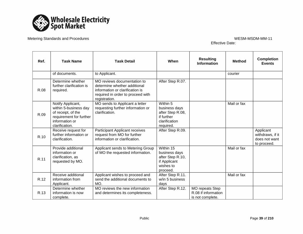
R.08
Determine whether further clarification is required.
MO reviews documentation to determine whether additional information or clarification is required in order to proceed with registration.
After Step R.07.
R.09
Notify Applicant, within 5-business day of receipt, of the requirement for further information or clarification.
MO sends to Applicant a letter requesting further information or clarification.
Within 5 business days after Step R.08, if further clarification required.
Mail or fax
R.10
Receive request for further information or clarification.
Participant Applicant receives request from MO for further information or clarification.
After Step R.09. Applicant withdraws, if it does not want to proceed.
R.11
Provide additional information or clarification, as requested by MO.
Applicant sends to Metering Group of MO the requested information.
Within 15 business days after Step R.10, if Applicant wishes to proceed.
Mail or fax
R.12 Receive additional information from Applicant.
Applicant wishes to proceed and send the additional documents to MO.
After Step R.11. w/in 5 business days
Mail or fax
R.13 Determine whether information is now complete.
MO reviews the new information and determines its completeness.
After Step R.12. MO repeats Step R.08 if information is not complete.

Metering Standards and Procedures WESM-MSDM-MM-11 Effective Date:
Public Page 40 of 210
Ref. Task Name Task Detail When Resulting
Information Method
Completion Events
R.14
Determine whether Applicant meets the qualifications for registration. w/in 5 business days
MO reviews the Applicant’s qualifications.
After Step R.13 or Step R.06, where information is complete.
MO proceeds to Step R.18 if satisfactory. Otherwise MO goes to R.13.
R.15
Advise Applicant within 15 business days of intention to deny registration, giving reason for the decision.
If the Applicant is deemed unqualified, the MO advises Applicant of intention to deny registration, stating reasons for this decision.
Within 15 business days after Step R.14, if Applicant does not comply with requirements.
Mail or fax
R.16
Receive notification of intention to deny registration.
Participant Applicant receives notification from MO of intention to deny registration.
After Step R.15. Mail or fax Applicant withdraws, if it does not wish to proceed.
R.17
Rectify the qualification deficiency or explain why qualifications should be acceptable to MO w/in 15 business days
If the Applicant wishes to proceed with registration, Applicant advises MO of actions taken or explanations as to why qualifications should be acceptable to MO.
Within 15 business days after Step R.16, if Applicant wishes to proceed with registration.
Mail or fax
R.18
Receive notification of action taken by Applicant and review explanations submitted.
MO receives and reviews the Applicant’s notification of action taken by Applicant or the explanations submitted.
After Step R.17. Decision on whether the Applicant now qualifies. If not, go to Step R.33. If

Metering Standards and Procedures WESM-MSDM-MM-11 Effective Date:
Public Page 41 of 210
Ref. Task Name Task Detail When Resulting
Information Method
Completion Events
yes, proceed to Step R.17.
R.19
Advise Applicant that MO is proceeding with the registration process
If the Applicant meets the registration qualifications, the MO advises Applicant of MO’s intention to proceed with the registration process
After Step R.18 Mail of Fax Applicant receives letter from the MO stating that the registration process will continue
R.20
Received Notification
Applicant had received the notification that its registration had been denied
Mail or fax Applicant’s Registration is denied – ERC to be notified by MO
R.21
Within 5 business days, notify Applicant of its successful registration as a Participant and payment of the Certification fee
Within 5 business days of the Applicant attending the Procedures Review, the MO notifies the Applicant of its successful Registration as a Participant. Upon payment of the Certification Fee,
After payment of the required fee, the Applicant shall receive notification of successful registration
R.22 The Participant shall receive notification of
After payment of certification fee, the Participant receives notification
After Step R.21.

Metering Standards and Procedures WESM-MSDM-MM-11 Effective Date:
Public Page 42 of 210
Ref. Task Name Task Detail When Resulting
Information Method
Completion Events
successful Registration as a new MSP, upon Payment of the Certification Fee.
of successful Registration
R.23
MO to establish the requirements as per MMS
These are among others: 1.) Feed in MSP’s registration
details & assigned short name 2.) Create new WESM Registry
User Set the required access privilege for the User through online Registry System & give to MSP the access code ETC
R.24
MO to issue Certificate of Registration with the Seal of MO
After payment of the certification fee, the participant shall receive the Certificate of Registration from the MO
After R.23
R.25
Update register of Participant
MO updates the registry of Participant with name of Applicant and publishes updated register on the MO Web site.
After Step R.24. Web publishing
Updated Participant Register published on the MO Web site.
R.26
Download, complete and submit to Participant, MO Form, Participant System
Download from the MO Web site, complete and submit the required form to your Metered Trading Participant. Participant signed MO
After Step R.25 System access for Participant Only is initiated.
Mail, courier or fax
System access requested.

Metering Standards and Procedures WESM-MSDM-MM-11 Effective Date:
Public Page 43 of 210
Ref. Task Name Task Detail When Resulting
Information Method
Completion Events
Access and Contact Information.
Forms to MO.
R.27
Receive MO-FORM.
The MO receives the System access information. Using “MO-FORM Participant Revenue Metering System Password” sends the password for the Market Management System (MMS).
After Step R.26 System access User IDs and Passwords
Participant has access to MO Systems. End of Registration procedure.

Metering Standards and Procedures WESM-MSDM-MM-11 Effective Date:
Public Page 44 of 210
SECTION 5 METERING INSTALLATION REGISTRATION 5.1. INTRODUCTION
All Trading Participants (Generators and Customers) who are direct WESM members, through their Metering Services Providers (MSP) are required to register their Metering Installations with the Market Operator (MO) before they will be allowed to participate in the WESM. 5.2. PREPARING FOR METERING INSTALLATION REGISTRATION In order to qualify for the registration of potential delivery points and be allowed to participate in the WESM, the Trading Participant and/or its Metering Services Provider must be able to demonstrate the following requirements prior to registration with the Market Operator (MO): 5.2.1. Read and understand relevant sections about the “Metering Installations”
detailing the requirements of the harmonized version of relevant sections of the WESM rules, the Philippine Distribution Code and the Philippine Grid Code;
5.2.2. Metering installations installed by the Trading Participant/Metering Services Provider shall consists of meters compliant with WESM rules:
5.2.3. Demonstrate to the Market Operator that the Trading Participant’s MSP has
successfully conducted a commissioning test for new Metering Installation. On the other hand, the Trading Participant’s MSP shall submit reports of all commissioning test for existing Metering Installation.
5.2.4. An End to End Test to satisfy the MO’s requirements on the successful
examination of the Metering Installation and ensure the accuracy of the meter data shall be performed by the Trading Participant’s MSP.
5.2.5. MSP shall demonstrate or provide proof that the metering equipment and
metering data are provided with adequate security system;
5.3. REGISTRATIONS AND SUBMITTALS
5.3.1. The three types of Metering Installations to be registered are:

Metering Standards and Procedures WESM-MSDM-MM-11 Effective Date:
Public Page 45 of 210
5.3.1.1. Main and alternate meter, of revenue quality meters, with the same
accuracy class and features. The alternate meter is not mandatory;
5.3.1.2. Main and check meter, of revenue quality meters, with the same accuracy class, but the check meter has lesser features than the main meter. The check meter is not mandatory;
5.3.1.3. Main or Single meter, of revenue quality type.
5.3.2. Pertinent Documents to be submitted by the Trading Participant in
coordination with its MSP: 5.3.2.1. Accomplished Metering Installation Form; 5.3.2.2. Metering Installation Specifications; 5.3.2.3. Load Profile (Forecast, Historical Data, including Maximum and
Minimum Hourly Demand) 5.3.2.4. Data of Connected Transformers (Core & Copper Loss) 5.3.2.5. Data of Radial Lines from the Market Trading Node to the Metering
Point. 5.3.2.6. Drawing of the Location Plan of the Metering Point; 5.3.2.7. Single Line Diagrams from Grid Substation to the Metering Point 5.3.2.8. Detailed Wiring Diagram of the Metering Installation 5.3.2.9. ERC’s Certification on Meter Test Results (with ERC Seal) 5.3.2.10. Test and calibration reports of Instrument Transformers and
Meters; 5.3.2.11. Pro-forma Agreement between Trading Participant and its MSP;
and 5.3.2.12. Other Special Features of the Meter.
Note: All drawings, plans, wiring diagrams shall be signed by a Professional Electrical Engineer (PEE).
5.4. WORKFLOW AND PROCEDURAL STEPS
The following diagram represents the work flow and information between the interfacing of the MO and the MSP in registering the Metering Installation. Also featured in this manual are the procedural steps to be followed by the Metering Services Provider in registering the Metering Installation/facilities.
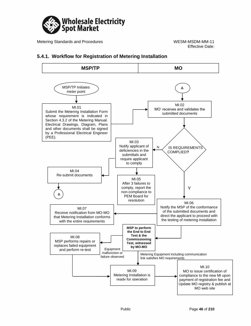
Metering Standards and Procedures WESM-MSDM-MM-11 Effective Date:
Public Page 46 of 210
5.4.1. Workflow for Registration of Metering Installation
MSP/TP MO
MI.07 Receive notification from MO-MO that Metering Installation conforms
with the entire requirements
MI.04 Re-submit documents
MI.02 MO’ receives and validates the
submitted documents
MI.01 Submit the Metering Installation Form whose requirement is indicated in Section 4.3.2 of the Metering Manual. Electrical Drawings, Diagram, Plans and other documents shall be signed by a Professional Electrical Engineer (PEE).
MI.06 Notify the MSP of the conformance
of the submitted documents and direct the applicant to proceed with the testing of metering installation
A
Y
N
MI.08 MSP performs repairs or replaces failed equipment
and perform re-test Equipment malfunction or
failure observed Metering Equipment including communication link satisfies MO requirements
MI.09 Metering Installation is
ready for operation
MI.10 MO to issue certification of
compliance to the new MI upon payment of registration fee and Update MO registry & publish at
MO web site
IS REQUIREMENTS COMPLIED?
MI.03 Notify applicant of deficiencies in the
submittals and require applicant
to comply
MI.05 After 3 failures to comply, report the non-compliance to
PEM Board for resolution
MSP to perform the End to End
Test & the Commissioning Test, witnessed
by MO-MO
MSP/TP Initiates meter point registration
A

Metering Standards and Procedures WESM-MSDM-MM-10 Effective Date: 03 October 2014
Public Page 47 of 210
5.5. PROCEDURAL STEPS FOR REGISTRATION OF METERING INSTALLATIONS
Ref. Task Name Task Detail When Resulting
Information Method
Completion Events
MI.01
Submission of Application Form and pertinent documents
Submit the application form with the following documents: Electrical Diagram, Metering Installation Specification and Documents, Metering Point Locations, Drawings, Load (Demand) Forecast of Metering Installation, Transformer Data, Agreement between MSP and TP (if any), Pictures of the Installation, Payment of Application Fee (submittals should be signed by a PEE)
MSP initiates the Metering Installation Registration
Application Forms with the required documents was submitted to MO
By courier
MO receives the documents.
MI.02
MO receives and validates the submitted documents
MO validates the application form and the Metering Installation documents for completeness and conformance to standards
Following receipt of Form and submittals from MSP
MI.03
Request clarification from MSP of requirements
The MO requests the MSP to provide further clarifications about the submitted forms and documents for no- conformance to MO requirements. If the MO decides the Metering Installation is not suitable for registration, then proceed to Step MI.05.
After the initial evaluation of the MO that submitted documents were found lacking in substance (if these circumstances happened
Notification by the MO requesting to fulfill its requirements
Fax, mail, or e-mail
The MSP receives the MO notification.

Metering Standards and Procedures WESM-MSDM-MM-10 Effective Date: 03 October 2014
Public Page 48 of 210
Ref. Task Name Task Detail When Resulting
Information Method
Completion Events
repeatedly, proceed to Step MI.05)
MI.04 Resubmit needed documents with clarification.
To continue the registration process, the MSP must resubmit to MO all the needed requirements.
After receiving the clarification request from the MO.
All the required documents with clarifications
mail or courier The MO receives the documents.
MI.05
MO-MO reports the non-compliance of the MI to the PEM Board for resolution
After 3 failures to comply with the requirements.
After MI.03
MO Board decides to reject the registration of the MI
Fax, mail or courier
MI is not included in the rolls of WESM Member
MI.06
Notify MSP the conformance of the entire requirements and request for End to End test
MO notifies the MSP that the Metering Installation described in the submitted documents conforms to MO standards and requests the MSP to perform the End to End test.
After evaluating that the submitted documents’ conform to MO’s requirements complete.
Notification by MO stating that the MSP’s documents conform to MO requirements.
Fax, mail, or e-mail
The MSP receives notification.
MI.07 Receive notification of conformance.
MSP receives notification of conformance and should pay the necessary registration fees.
After Step MI.06. Fax, mail, or e-mail

Metering Standards and Procedures WESM-MSDM-MM-10 Effective Date: 03 October 2014
Public Page 49 of 210
Ref. Task Name Task Detail When Resulting
Information Method
Completion Events
MI.08 MSP to rectify all uncovered problems
MSP has corrected the problems/failures concerning the end to end test
After MSP performs the end to end test by and uncovers some failures or problems
MSP’s Metering Installation is ready for testing
MI.09 Metering Installation is ready for operation
MSP’s Metering Installation satisfactorily passed the end to end test as witnessed by MO and ready for operation,
After MI.08
MI.10
Updating of the MO’s registry and Publishing it at MO’s Web site
MO to issue a certificate of compliance to the new Metering Installation upon payment of registration fee and Update its registry and published the new Metering Installation of the MSP at MO’s Web site
After MI.09
End of registration process of MSP’s MI

Metering Standards and Procedures WESM-MSDM-MM-11
Effective Date:
Public Page 50 of 210
SECTION 6 METERING DATA COLLECTION
6.1. INTRODUCTION The Metering Services Provider (MSP) is primarily responsible for and in behalf of the Trading Participant (TP) to collect and deliver Metering data to the Market Management System (MMS) of the Market Operator (MO). Revenue Meters and/or data collection system of the MSP must be capable of electronic, remote communication with the MO’s meter Interrogation System to transfer Metering data. The MO will publish on its web site the metering data for the time period covered by the settlement process in accordance to section 4.8 of the WESM rules. If remote acquisition of metering data becomes unavailable, the MO will contact the Metered TP or MSP to arrange an alternate means of transferring the data. 6.2. DATA COLLECTION The meter data collection process shall be done in the following manner: 6.2.1. The Registered MSP shall collect meter data the previous day (for the 24
hour period) from each Metering Points of their respective TPs (Generators or Customers) including meters which are remotely connected by means of their meter data retrieval systems starting at 12 midnight. Then all configured data shall be transmitted to the MMS every 4 AM the succeeding day. However, the MSP shall not make, cause or allow any alteration to the original stored meter data as retrieved in the metering installation; and
6.2.2. In case of remote communication failure, with prior notice to MO, the MSP shall manually retrieve the meter data and transmit or deliver it to the MMS.
6.2.3. However, MO may opt to perform remote data collection on the affected
meters using its own MMS’s data collection system with prior notice to the MSP.
All meter data delivery/transmittal shall be in accordance with established procedures. All meter clocks shall be synchronized by the MSP with the Philippine Standard Time (PST) to ensure accuracy of settlements as per section 4.5.8 of the WESM rules.

Metering Standards and Procedures WESM-MSDM-MM-11
Effective Date:
Public Page 51 of 210
6.3. METERING DATABASE The Metering data recorded in the Metering database with respect to a registered wholesale meter is confidential information and will only be made available to: 6.3.1. TP whose settlement statement is determined on the basis of the Metering
data recorded in that registered wholesale meter;
6.3.2. The MSP for that registered wholesale meter; and 6.3.3. Network Service Provider to whose system a TP is connected using a
separate WESM Metering Installation.
The TP may query the Metering database for the purpose of reviewing the Metering data to determine its correctness.
6.4. INTERFACE AND DATA FLOW Pursuant to Section 4.6 of the WESM Rules, the data that comes in from the Data collection system shall be subjected to Validation, Estimation and Editing (VEE) processes to ensure integrity of the metered data for settlement purposes. This MMS process involves various interfaces which comprises the following:
6.4.1. The MSP will collect daily the 24-hour metered data of the previous day
and shall transmit/deliver it to the MMS of the MO within the 4th hour of the succeeding day.
6.4.2. The following contents shall be needed by the MMS from the metered data: 6.4.2.1. Date and time (Time Series) of meter readings received for each
meter and the Meter data exchange format. 6.4.2.2. The meter data in kwh (Energy) with assigned channel number. 6.4.2.3. Site Equipment Identification Number (SEIN) or Recorder ID of
Meter (RevMeterID/Meter Point). 6.4.2.4. Meter Serial Number 6.4.2.5. Substation (Market Node) 6.4.2.6. Substation Voltages 6.4.2.7. Resolution (every 15 minute) 6.4.2.8. Minimum and Maximum Value of meter data

Metering Standards and Procedures WESM-MSDM-MM-11
Effective Date:
Public Page 52 of 210
6.4.3. The Metering Services Provider shall submit the metering data in meter data exchange format or any other secured format as required by the Market Operator.
6.5. WORKFLOW AND PROCEDURAL STEPS The following diagram represents the work flow and procedural steps regarding the interfacing of the MSP and the MO in relation to the metered data. 6.5.1. Metering Data System Workflow
Registered?
Data Collection
System
N
Estimating Editing
Market Settlement
Y
Market Database
Y
Pass
Fail
Problem Repaired
N
Load Profile History
Missing Values
Trouble Investigation
Trouble Call
Meter Installation Testing
Site Specific Loss Adjustment
Must be resolved within two days
Market Publication
Forecasting Engine
MeterData
Automatic or Manual Retrieval
Measurement & Recording
Meter
MMS Data Retrieval System
MSP
MO
Do not process data
MSP Data Retrieval System
Meter Registry
Data Warehouses
Validation
Substitution
Meter Error Log
DC.07
DC.06
DC.05
DC.04 DC.03
DC.02 DC.01
DC.08
Meter Registration

Metering Standards and Procedures WESM-MSDM-MM-11
Effective Date:
Public Page 53 of 210
6.5.2. Metering Data Collection Workflow
Automatic or Manual Retrieval System
Measurement & Recording
Meter
MSP
MO
MSP Data Retrieval System
MMS Data Retrieval System

Metering Standards and Procedures WESM-MSDM-MM-11 Effective Date:
Public Page 54 of 210
6.6. METERING DATA COLLECTION PROCESS
Ref
Requirement
Frequency/Method
Where/Who
From
To
DC.01 Measuring and recording of Metered data (kWh, Kw, kVArh and kVAr)
Continuous, 15-minute interval
Meter/MSP MSP MO
DC.02 Recording of event logs Per occurrence Meter/MSP MSP
MO
DC.03a Electronic downloading of Metered data/event log
Daily Automatic
MSP Meter MSP
DC.03b Manual downloading of Metered data/event log
Daily As instructed by MO in case of meter trouble.
MSP Meter Temporary Collection System (e. g. laptop)
DC.03c Uploading of Metered data/event log
Daily Automatic
MSP MSP Temporary
Collection System MO Meter Data
Collection System

Metering Standards and Procedures WESM-MSDM-MM-11
Effective Date:
Public Page 55 of 210
6.7. METER DATA RETRIEVAL SYSTEM 6.7.1. The MMS Data Retrieval/Collection System of the MO has three (3)
different ways to communicate with the meters and communication system with MSP, to wit:
6.7.1.1. Meter Data Retrieval of MSP to Meter Data Collection System of
MO 6.7.1.2. Meter Data Flat File to Meter data Collection System of MO 6.7.1.3. Meter to Meter Data Retrieval/Collection System of MO

Metering Standards and Procedures WESM-MSDM-MM-11
Effective Date:
Public Page 56 of 210
6.7.1.1 Meter Data Retrieval System (MDRS) of MSP to Meter Data Collection System (MDCS) of MO:
MSP’s MDRS retrieves the 15-minute raw Meter data of the previous day (00:00H to 24:00H) through Digital Telephone System
(DTS)/PLDT (landline) or any communication that will suit the MDRS
The MDRS of MSP is directly connected to the registered meter which is
automatically interrogated daily. The Meter is uniquely identified by its
Recorder ID (SEIN) and Device ID (Serial Number)
Meter Meter stores data every 15
minutes
MO calls on the MSP to resend data (Customer ID,
Recorder ID, Device ID, Date and Time Series, raw Meter
data, etc)
At 04:00H, MO’s MDCS receives the data (Customer ID,
Recorder ID, Device ID, Date
and raw data, etc) from MSP’s MDRS
The data (Customer ID, Recorder ID, Device ID, Date and Time Series, raw Meter data) is
automatically exported to MO’s MDCS through file transfer protocol
A
MO’s MDCS configures the raw Meter data into the
required file format
Communication Module
A

Metering Standards and Procedures WESM-MSDM-MM-11
Effective Date:
Public Page 57 of 210
6.7.1.2 Meter Data Flatfile to Meter Data Collection System of MO:
Meter Meter stores data every 15
minutes
MSP uses a Meter reader handheld device/laptop computer to directly download the 15-minute raw data from the registered Meter using a
communication cable to link the registered Meter and the Meter reader handheld device/laptop. The registered Meter is uniquely identified by its
Recorder ID (SEIN) and Device ID (Serial number)
At the nearest Trading Participant office (or any office near the meter site where
there is available communication), the data (Customer ID, Recorder ID, Device ID,
Date and Time Series, raw meter data) is sent through email to the MSP office
MSP receives the data (Customer ID, Recorder ID, Device ID, Date and Time Series, raw Meter
data) and uploads it to their Meter Data Retrieval System
(MDRS)
The MDRS of MSP automatically exports the data (Customer ID, Recorder ID, Device ID, Date and Time Series, raw Meter data) to the MDCS
of MO through file transfer protocol
MO calls on the MSP to resend data (Customer ID,
Recorder ID, Device ID, Date and Time Series, raw Meter
data)
MO’s MDCS receives the data (Customer ID, Recorder ID, Device ID, Date and Time
Series, raw Meter data) from MSP’s MDRS
Communication Module
A
MO’s MDCS configures the raw Meter data into the
required file format
A

Metering Standards and Procedures WESM-MSDM-MM-11
Effective Date:
Public Page 58 of 210
6.7.1.3 Meter to Meter Data Retrieval/Collection System of MO.
MO’s MDRS is directly connected to the registered meter, identified uniquely by its Recorder ID (SEIN) and Device ID
(Serial Number)
The registered Meter is automatically interrogated daily
Meter Meter stores data every 15
minutes
MO’s MDRS retrieves the 15-minute raw meter data of the previous day (00:00H to
24:00H) from the registered Meter through the Digital Telephone System (DTS)/PLDT
(landline) or any communication that suit the MDRS
MO’s MDRS configures the raw data into the required file format
Communication Module

Metering Standards and Procedures WESM-MSDM-MM-11 Effective Date:
Public Page 59 of 210
6.8. METER DATA RETRIEVAL/COLLECTION PROCEDURE 6.8.1. MSP’s Meter Data Retrieval System to Meter Data Collection System of MO
Ref
Requirement
Frequency/Method
Where/Who
From
To
1 Meter reads and stores data Continuous, 15-minute
interval Meter
2
Retrieval of raw meter data of the previous day (0000H-2400H) through DTS/PLDT or any available communication line
Daily
Automatic Meter/MSP Meter MSP’s MDRS
3 Meter data is exported to MO (0400H) next day
Daily Automatic
MSP MSP’s MDRS MO’s MDCS
4 Meter data is received by MO
Daily
Automatic MO
5 Configure the raw meter data to Required file format
Daily Automatic
MO

Metering Standards and Procedures WESM-MSDM-MM-11 Effective Date:
Public Page 60 of 210
6.8.2. Meter Data Flat File to Meter Data Collection of MO (In case of communication failure)
Ref
Requirement
Frequency/Method
Where/Who
From
To
1 Meter reads and stores data Continuous, 15-minute
interval Meter
2 Retrieval of raw meter data through meter reader handheld device or laptop
Daily/Weekly
Manual Meter/MSP Meter
Meter Reader Handheld
Device/Laptop
3 Meter data is e-mailed Per occurrence MSP MSP (Field) MSP (Main) where the
MDRS is located
4 Meter data is received & uploaded to MDRS
Per occurrence MSP
5 Meter data is exported and received by MO’s MDCS
Automatic MSP MSP’s MDRS MO’s MDCS
6 Configuration of raw meter data to the required file format
Automatic MO

Metering Standards and Procedures WESM-MSDM-MM-11 Effective Date:
Public Page 61 of 210
6.8.3. Meter to Meter Data Retrieval System of MO
Ref
Requirement
Frequency/Method
Where/Who
From
To
1 Meter reads and stores data Continuous, 15-minute
interval Meter
2
Retrieval of raw meter data of the previous day (0000H-2400H) through DTS/PLDT or any available communication line
Daily
Automatic Meter/MO Meter
MO’s MDRS
3 Configuration of raw meter data to the required file format
Daily
Automatic MO

Metering Standards and Procedures WESM-MSDM-MM-11
Effective Date:
Public Page 62 of 210
6.9. EMERGENCY PROCEDURES
In case of failure of MSP’s Meter Data Retrieval System (MDRS) and/or emergency situations that require transfer of the MO metered data processing operation from the Main Server to the Emergency Back-up System (EBS), the procedural steps to address the situation shall be as follows:
6.9.1. Failure of the MSP Meter Data Retrieval System
6.9.1.1. MSP
6.9.1.1.1. Inform MO of the occurrence of the failure of its
MDRS.
6.9.1.1.2. Perform emergency restoration of its MDRS.
6.9.1.1.3. While the MDRS is out of service, retrieve all required metered data using alternative methods of retrieval and submit it within seven (7) days to MO in a file format that is compatible with the MO system. .
6.9.1.1.4. For this purpose, the MSP may use a backup MDRS if
it is available, or retrieve the metered data on-site or remotely using the proprietary meter software.
6.9.1.2. MO Upon receipt of metered data, perform VEE and process the metered data for billing and settlement.
6.9.1.3. MSP
6.9.1.3.1. Inform MO when its MDRS is ready to resume normal
operation.
6.9.1.3.2. Resume normal retrieval and transmittal of metered data using the MDRS
6.9.2. In case of technical problems and emergency situations at the MO Main Server that necessitate transfer of operation to the Emergency Back-up System (EBS):

Metering Standards and Procedures WESM-MSDM-MM-11
Effective Date:
Public Page 63 of 210
6.9.2.1. MO 6.9.2.1.1. Inform the MSPs and the TPs of the need to transfer
operations from the Main Server to the EBS; and instruct MSPs to transmit the metered data to the EBS.
6.9.2.1.2. Activate the EBS, upload the metered data and
perform VEE process for billing and settlement.
6.9.2.1.3. Performs emergency restoration of its Main Server
6.9.2.2. MSP Transmit the metered data to MO-EBS.
6.9.2.3. MO When the MO is ready to resume operation at the Main Server, inform the MSPs to resume metered data transmittal to the Main Server.
6.9.2.4. MSP Resume transmittal of metered data to the MO Main
Server.
6.9.2.5. MO Resume operations at the Main Server. Upload the meter data and perform VEE process for billing and settlement.

Metering Standards and Procedures WESM-MSDM-MM-11
Effective Date:
Public Page 64 of 210
6.9.3. Failure of MSP Meter Data Retrieval System
MSP inform MO about the failure of MSP’s
MDRS to interrogate the meter data every 24 hours.
MSP retrieves the metered data from the all metering sites using alternative methods of data retrieval and transmit the data to MO
within seven (7) days.
MO uploads the meter data to MDW of the MMS and process the
data for billing and settlement.
MSP to perform Emergency Restoration
of its MDRS
Upon restoration of MDRS, MSP informs
MO that its MDRS is ready to operate.
MSP resumes normal daily retrieval and
delivery of meter data through the MDRS.
General Failure of the MSP’s MDRS

Metering Standards and Procedures WESM-MSDM-MM-11
Effective Date:
Public Page 65 of 210
6.9.4. Switching of Servers from Main Site to EBS by MO
MO decides to switch servers from Main to EBS
MO informs all MSP and all TP that MO to switch servers from its Main to the EBS.
Instruct all MSP to transmit the Metered data to the EBS.
All MSP transmit metered data to the EBS. MO activates the EBS.
MO uploads the metered data and performed VEE process for billing
and settlement.
MO performs emergency restoration of its Main Server.
Upon restoration of MO’s Main Server, inform all MSP to resume metered data
transmittal to MO’s Main Server.
All MSP resume transmittal of meter data to MO’s Main Server.

Metering Standards and Procedures WESM-MSDM-MM-11
Effective Date:
Public Page 66 of 210
SECTION 7 DATA VALIDATION, ESTIMATION AND EDITING
7.1. INTRODUCTION The Metering data collected by the Market Operator (MO) shall be reviewed using the Validation, Estimation, and Editing (VEE) process. The VEE process operates according to established schedule that ensures the integrity of the metered data suitable for settlement purposes as per Section 4.9 of the WESM rules. 7.2. GENERAL DESCRIPTION OF THE VEE PROCESS
7.2.1. The VEE Perspective At the time the metered data were received by the Market Management System (MMS), it shall be evaluated using criteria as agreed among Trading Participants, Metering Services Provider (MSP) and the MO. Whether the metered data contains missing values, uncertain values or exceeds the max/min values, such data shall undergo validation, estimation and editing wherein substitutions of metered data should follow the establish policy using historical data or the best available information. In cases where metered data fails in the VEE process, MO will then issue trouble report and give instruction to the concerned MSP who should investigate the trouble and provide report to MO later. The concerned Metering Services Provider may propose an adjustment to the edited value based on confirmed nature of failures. Once the metered data had undergone verification, all concerned parties including MO must agree to the proposed change. 7.2.2. Custodian of Metering Database MO shall establish and maintains a database containing metered data transferred from each registered wholesale meter to the MMS in accordance with section 4.8.2 of the WESM rules. The metering database includes original energy readings, substitutions, estimations, and calculated values for all WESM complaint meters.

Metering Standards and Procedures WESM-MSDM-MM-11
Effective Date:
Public Page 67 of 210
7.3. THE VEE PROCESS
7.3.1. Meter Value Validation
When the metered data is received by the MMS, several checks will be performed. The time series that fails the test will be reported according to four error categories:
7.3.1.1. Uncertain Value 7.3.1.2. Missing Values 7.3.1.3. Outside Min/max limits 7.3.1.4. Orphan values
7.3.2. Checks to be performed for the Meter Data The following checks will be performed for the above values:
7.3.2.1. Evaluate the meter’s maximum and minimum readings.
7.3.2.2. Verify the values of the check meter if check meter is available.
7.3.2.3. Verification for the values of the metered data whose meter is not registered in the MMS, master lists which are known as the “Orphan Values”.
7.3.2.4. Review the historical meter readings which fall outside defined
parameters max/min of the historical data. The historical data used for reasonability check is limited to:
a. Same value as last week b. Same value as the same hour during the previous day of
the same type (i.e. weekday or weekend)
7.3.3. Meter Values Validation Configuration Minimum and maximum values for the metered data are recorded in the registry of the MMS’ metering system. Any value that falls outside the range will be marked with status “uncertain”.
7.3.3.1. Check against Historical Values Check against historical meter data is executed by clock control or manually. This validation uses the following historical values: a. Same value as last week

Metering Standards and Procedures WESM-MSDM-MM-11
Effective Date:
Public Page 68 of 210
b. Same value as the previous day c. Average of previous day
7.3.3.2. Check against Check Meter (if necessary)
The verification of values of the check meter is recorded in the MMS and the parameters to be checked should follow the same period.
7.3.4. Meter Values Validation Reporting A special report is shown in the MMS wherein the errors in the three categories below are reflected:
7.3.4.1. Uncertain value. Values that failed the test against the check meter, the historical data check or the balance test.
7.3.4.2. Missing Values. This check is performed directly in the time series matrix.
7.3.4.3. Outside min/max limits. This check is performed directly in the
time series matrix.
7.3.4.4. Comparing the check meter to another meter (main or alternate meter measuring the same power flow).
7.3.5. Meter Value Estimation Meter values that are missing will be estimated and substituted for settlement purposes. This estimate shall be based on the following items:
7.3.5.1. Same value as last week
7.3.5.2. Same value as the same hour during the previous day of the same day type (i.e. weekday or weekend)
7.3.5.3. If the meter value for one interval is missing, estimation based
on Interpolation between values
7.3.5.4. If the meter values for two or more intervals are missing, meter data from the alternate meter
7.3.5.5. In the absence of an alternate meter, historical data previously gathered from the main meter

Metering Standards and Procedures WESM-MSDM-MM-11
Effective Date:
Public Page 69 of 210
7.3.5.6. For generators without alternate meters or historical, the real
time ex-post (RTX) information The estimated meter values shall be updated to their correct value upon submission by the Metering Services Provider (MSP) of the actual meter data obtained from the WESM compliant meters within the required period. A settlement recalculation run will be undertaken to implement the correct meter values into the settlement equation.
7.3.6. Meter Value Approval All meter data that are received must be approved by the MO before they are used in the settlement process. These data are reviewed and verified using the methods as discussed in sections 7.1 to 7.5. 7.3.7. Meter Value Export Settlement-ready values will be ready for transfer to the settlement process. Only approved values are transferable. 7.4. VEE – ESSENTIAL INDICATORS
7.4.1. Validation Tests for all Metering Installation The MSP may perform its own validation of Metering Installation. The following are the validation test that maybe performed by the MSP.
7.4.1.1. Current and Voltage Check
This indicator detects the loss of voltage and/or current input to the meter due to failure of the supply from one or more instrument transformers or tampering.
7.4.1.2. Load Profile vs Meter Reading
These checks for corruption related to the meter multiplier.
7.4.1.3. Intervals Found vs. Interval Expected
Checks for missing intervals.
7.4.1.4. Time Synchronization

Metering Standards and Procedures WESM-MSDM-MM-11
Effective Date:
Public Page 70 of 210
Checks for synchronism of meter clock to Philippine Standard Time/Data Collection System time.
7.4.1.5. Number of Power Outage Intervals
This indicator allows periods of zero primary power to be identified.
7.4.1.6. CRC/ROM RAM CRC pertains to the hardisk, ROM is read only memory and RAM is random access memory. This is part of the internal component of the meters, which automatically flags down indicating failure of internal electronics of the meter.
7.4.1.7. Meter Clock over Flow
Flag generated by the meter indicating failure of internal electronics.
7.4.1.8. Hardware Reset
Flag generated by the meter indicating failure of internal electronics.
7.4.1.9. Time Reset
Indicates the interval in which the meter clock time has been changed creating either a shorter or longer interval.
7.4.1.10. Data Overflow on Interval
This indicates that the meter is creating more pulses than it can record in an interval or Data Collection System (DCS) can accommodate in an interval.
7.4.1.11. Number of Channels
The actual number of data channels from the meter does not match the number expected at the data collection System.
7.4.1.12. Changed Device ID

Metering Standards and Procedures WESM-MSDM-MM-11
Effective Date:
Public Page 71 of 210
The internal device identifier does not match the value registered at the data collection System.
7.4.1.13. Watch Dog Time Out This is the failure of the meter to return data in response to a poll within the required time frame. This is reported by some recorders when a watchdog register is tripped or activated.
7.4.1.14. Parity Error This indicator determined by a parity error bit that is set by a recorder on a channel of data during status check or read/write function.
7.4.1.15. Event Log Check
Checks error messages and alarms recorded by the meter.
7.4.2. Main/Alternate/Check Meter Combination
Data from the alternate/check meter can be directly substituted for the main meter provided the equipment in the alternate/check meter installation is of revenue quality. However, if the main and the alternate/check meters are not installed at the same Connection Point, the alternate/check meter data must be adjusted to account for the physical losses.
7.4.2.1. Additional Tests Required for Main/Alternate/Check Meter
Combination a. Energy Comparison
For each dispatch interval (1 hour), the kWh delivered of the main meter shall be compared with the kWh delivered of the alternate/check meter. If the difference exceeds a predefined limit, Validation fails and a trouble call shall be issued. The process shall be repeated for kVArh delivered, kWh received and kVArh received of the main. Note:
The assignment of channel numbers in the main and alternate/check meter must be the same.
The predefined limit shall be associated with the main meter data.

Metering Standards and Procedures WESM-MSDM-MM-11
Effective Date:
Public Page 72 of 210
b. Demand Comparison
For each dispatch interval (1 hour), the active and reactive power demand values of the main meter shall be compared with the active and reactive power demand of to alternate/check meter.
7.4.2.2. Stand-alone Metering a. Generally, the validation shall check the
maximum/minimum energy limit and comparing it to historical data. The MO may opt to check/validate using its data collection system which is capable of performing the following test. No source of comparison data is available in stand-alone Metering; therefore, Validation must be based on the available data at hand.
i. High/Low Limit on Interval
Specifies maximum and minimum interval demand when exceeded.
ii. High/Low Limit on Energy
Specifies maximum and minimum energy when exceeded over the period being validated.
iii. Percentage Change on Interval
Flags validation failure if consecutive intervals differ by more than the specified intervals.
iv. Load Factor Tolerance
Flags Validation failure when the average load divided by the maximum load over the period being validated exceeds the prescribed level.
v. Power Factor Limit

Metering Standards and Procedures WESM-MSDM-MM-11
Effective Date:
Public Page 73 of 210
Flags a Validation failure when the average power factor over the period being validated is less than the specified minimum.
vi. Zero Interval Tolerance Flags a Validation failure if the total number of intervals containing zeroes over the period being validated exceeds the tolerance limit.
b. Voltage Check i. If the values in all voltage channels is within the
prescribe level, validation succeeds. ii. If the values in one or two but not in all voltage
channels are zero, a failure in the supply voltage is indicated.
iii. If the values in all voltage channels are zero and any of the current channels contain data, a failure in the supply voltage is indicated.
iv. If the values in all voltage and current channels are zero, the Validation succeeds.
c. Current Check i. If the values in all current channels are greater than
zero, Validation succeeds. ii. If the value in one or two but not in all current channels
is zero, a failure in the supply current is indicated. iii. If all current values are zero, Validation succeeds.
7.4.3. Estimating, Editing and Substitution
When Validation indicates that the data from the main meter might be incorrect, the VEE software will automatically prepare an estimate. Data from the alternate or check meter will be substituted if these data passed Validation. If no other data is available or if data from alternate or check meter is also a suspect (fails Validation), the estimate shall be prepared based on the historical load pattern.
7.4.3.1. Main/Alternate/Check Metering a. When energy comparison test fails, a trouble call shall be
initiated to establish which meter data is incorrect. The alarms registered in the event log shall be examined to determine whether the problem is associated with the

Metering Standards and Procedures WESM-MSDM-MM-11
Effective Date:
Public Page 74 of 210
failure of the main meter. If all tests carried out on the main meter do not indicate a problem, no Substitution from the alternate to the main shall be carried out.
b. If a test carried out on the main meter indicates a problem, data from the alternate/check meter shall be substituted for each dispatch interval where the energy comparison test fails. The data from the alternate/check meter shall pass the Validation tests before any Substitution is done.
c. If a test carried out on the main meter indicates a problem
and the data from the alternate/check meter does not pass validation (or the alternate/check meter also indicates a problem), an estimated data based on historical load pattern shall be substituted.
d. The decision to use the substituted data in the settlement process shall be based on the results of the trouble call investigation.
7.4.3.2. Stand-Alone Metering
For stand-alone Metering, estimating shall be based on historical load pattern since no other data is available. Estimation Methods is in accordance with sections 3.1 to 3.5.
7.4.3.3. If there is insufficient data to implement the two methods, the method agreed between the TP and MO shall be applied automatically.
7.4.3.4. Use of Meter Register Reading Reading in VEE (As approved by PEM Board Resolution No. 2010-57 dated 25 August 2010)
Meter Register Readings (Present Index & Previous Index corresponding to the start and end of the period to be settled) may be used for the VEE process under the following circumstances: a. Non availability of load profile capable meter b. Failure of both main and alternate meters c. Load profile data of the main/alternate meters is corrupted The trading participant through its MSP is required to submit the meter register readings from an installed Statistical or Revenue-

Metering Standards and Procedures WESM-MSDM-MM-11
Effective Date:
Public Page 75 of 210
class meter subject to the review and acceptance of the MO for use in the VEE process, based on the following criteria: a. The meter where the register readings are taken measures
the energy at the same metering point as the main meter. If the meter is not measuring at the same metering point as the main meter, corresponding adjustments for line and transformer losses shall be applied to the register readings.
b. The meter where the register readings are taken is certified by the MSP to have been tested and the error is quantified in a test report.
c. The register readings are adjusted for the meter error.
The meter register readings shall be treated by the MO in the following manner: a. The hourly equivalent meter data shall be computed
proportionately according to the load shape obtained from available RTU data corresponding to metering point for the time covered by the register readings, or to the load shape obtained from the historical load profile data for a similar day and time.
b. The hourly equivalent meter data shall undergo site – specific loss adjustment for any equipment between the market trading node and the meter.
c. Register readings for succeeding settlement periods shall be submitted by the trading participant through its MSP and shall be used by the MO until a load profile meter data is available.
7.4.3.5. The decision to use the substituted data in the settlement process shall be based on results of the trouble call investigation.
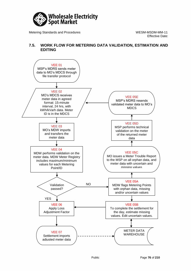
Metering Standards and Procedures WESM-MSDM-MM-11
Effective Date:
Public Page 76 of 210
7.5. WORK FLOW FOR METERING DATA VALIDATION, ESTIMATION AND EDITING
VEE 01 MSP’s MDRS sends meter
data to MO’s MDCS through file transfer protocol
VEE 02 MO’s MDCS receives meter data in agreed
format: 15-minute interval, 24 hrs, with
kWh/kVarh data. Meter ID is in the MDCS
Masterfile
VEE 03 MO’s MDW imports
and transfers the meter data
VEE 04 MDW performs validation on the meter data. MDW Meter Registry
includes maximum/minimum values for each Metering
Point/ID
Validation passed?
VEE 05A MDW flags Metering Points with orphan data, missing and/or uncertain values
VEE 05B To complete the settlement for
the day, estimate missing values. Edit uncertain values.
VEE 06 Apply Loss
Adjustment Factor
VEE 07 Settlement imports adjusted meter data
METER DATA WAREHOUSE
NO
YES
VEE 05C MO issues a Meter Trouble Report to the MSP on all orphan data, and
meter data with uncertain and missing values
VEE 05D MSP performs technical validation on the meter of the returned meter
data
VEE 05E MSP’s MDRS resends
validated meter data to MO’s MDCS

Metering Standards and Procedures WESM-MSDM-MM-11 Effective Date:
Public Page 77 of 210
7.6. PROCEDURAL STEPS FOR VALIDATION, ESTIMATION AND EDITING PROCESS
Ref. Task Name Task Detail When Resulting Information Method
VEE 01 Sending the meter data MSP’s MDRS sends meter data to MO’s MDCS
0745 H daily Meter data is in the shared folder for file transfer protocol in the MDCS terminal
File transfer protocol
VEE 02 Receiving the meter data MO’s MDCS receives meter data in agreed format
After meter data has been sent by the MSP
Meter data is in 15min interval by 24 hours with kWh and kVarh data. Meter ID is recognized by MDCS Masterfile
None
VEE 03 Importing the meter data Meter data is imported by MDW and the files are transferred
After meter data has been recognized by MDCS Masterfile
Meter data is recognized by MDW Masterfile
File import/transferred
VEE 04 MDW validation MDW validates the meter data for good, orphan, uncertain, and missing values. MDW Meter Registry includes maximum/minimum values for each Metering Point.
After meter data has been imported by the MDW.
Meter data with orphan, missing and/or uncertain values are indicated in the MDW interface
Automatic validation
VEE 05A Marking the validated meter data with flags
MDW flags meter data as orphan data, and meter data with missing and/or uncertain values
After meter data has been validated for maximum and minimum values limit.
Meter data values with flags Automatic marking of flags
VEE 05B MDW Estimation and Editing for daily settlement.
Manual estimation and editing of meter data with missing and/or uncertain data.
After meter data with flags are indicated in the MDW interface
Estimated missing values and edited uncertain values
Manual estimation and editing based on historical values
VEE 05C Returning the orphan meter data and meter data with uncertain and missing values
MO issues a Meter Trouble Report to the MSP on all orphan data and meter data with uncertain and missing values
After meter data has been validated for maximum and minimum values limit
Returned orphan data and meter data with uncertain and missing values in the Meter Trouble Report
File transfer
VEE 05D MSP validation MSP performs technical validation on the meter of the returned meter data
Upon receipt of the returned meter data
Re-validated meter data Per occurrence automatic validation
VEE 05E Resending the meter data MSP’s MDRS resends re-validated meter data to MO’s MDCS
After the MSP validation on the meter of the returned meter data
Re-validated meter data File transfer
VEE 06 Application of Loss Adjustment factor
The site specific loss adjustment factor is computed for each metering point and is applied.
After validation, estimation and editing of meter data
Adjusted metering data Manual computation for loss adjustment factor.
VEE 07 Settlement Import Settlement imports corrected meter data for preliminary settlement
After application of loss adjustment factor
Meter data is stored in the MDW --

Metering Standards and Procedures WESM-MSDM-MM-11
Effective Date:
Public Page 78 of 210
SECTION 8 METER TROUBLE REPORT
8.1. INTRODUCTION This chapter provides for instructions to the Trading Participants (TP) and their Metering Services Provider (MSPs) for the processing of Meter Trouble Reports (MTRs) to investigate potential problems with revenue Metering Installations. The Metering Services Provider of TP should review the entries in the metering database in a timely manner so that discrepancies can be addressed before the preliminary settlement statement is issued by the MO. The MO will issue an MTR to the MSP for the affected meter to investigate the problem, perform repairs as required, and provide substitute metering data in accordance with this procedure. 8.2. METER TROUBLE REPORT (MTR) The MO issues an MTR to the MSP for each meter for which it is responsible with data that fail the validation process, including missing data. MTRs are initiated by the said Metering Group, MSPs and/or TPs who experience difficulties communicating with a Metering Installation or validation of meter data. An MSP and/or TP may inform and request that the MO to issue an MTR. Where the MO determines that an MTR is not required, it notifies the TP and/or MSP of its decision. The market rules contain strict timelines with respect to MTR processing. These timelines are required to ensure prompt resolution of all MTRs and maintain the integrity of the settlements process. MSPs are expected to meet these timelines and all exceptions are tracked by the MO. MTRs that are not resolved within timelines specified in the Metering standard can trigger sanctions and data estimates for the Metering Installation of the TP. The MO is required to issue a MTR within 24 hours after its detection, to the associated MSP and promptly notify the TP when it becomes aware of a potential defect or malfunction at a Metering Installation. After notification and within two (2) business days, the MSP is required to implement the Emergency Restoration Plan and shall also inform the MO of such plan. If the MTR is still unresolved after seven (7) business day, the MO shall implement estimates (historical loading) for the resolution of the preliminary settlement of the Trading Participant. The MSP is also allowed up to twelve (12) business weeks to rectify the instrument transformer malfunction.

Metering Standards and Procedures WESM-MSDM-MM-11
Effective Date:
Public Page 79 of 210
8.2.1. Improving Efficiency in Resolving MTRs In case of outages, a TP and/or its MSP shall notify MO within 24 hours after its occurrence. All TPs may use the Metering Outages Form to notify their MSP and MO of any outages that may affect the metering data. The MSP will use this information to resolve MTRs that have been issued. Appendix A shows a sample of the form and instructions for completion. To access the MTR system, individuals in a TP or MSP organization, require a User ID and password. To obtain a User ID, download the following form from the MO Web site and complete it as directed including the appropriate signatures. Return the completed form to the MO. The Information Systems Group of MO will notify the user of the User ID and password. 8.2.2. Unresolved MTRs As described in Section 2.0 of this document, the MO can implement the VEE of metering data, when MTRs are not resolved within specific periods. These estimates remain in place until the MTR is rectified to the MO’s satisfaction. If the MSP resolves the MTR and subsequently provides metering data acceptable to the MO for the period in which the estimates were created, the MO replaces those estimates with that metering data. The TP/MSP must make the metering data available to MO within three (3) to seven (7) business days before the final statement date(s) for the trading day(s) affected. If the TP/MSP does not make the metering data available to the MO by this deadline, the MO estimates will appear on the final statement. If the MSP submitted the report after the final settlement period, the said adjustment will be reflected on the following billing period. In cases where there is unintentional meter error (e.g. meter multiplier) that causes meter malfunction occurred in the process, a prescribe period of one year is allowed for reconciliation from the date of discovery of such error. 8.3. PROCEDURAL WORK FLOW The procedural work flow contains graphical representations of the steps and flow of information related to MTR procedure between the MO, the primary external participant, the TP and its MSP involved in the procedure, and any other parties.

Metering Standards and Procedures WESM-MSDM-MM-11
Effective Date:
Public Page 80 of 210
8.4. WORKFLOW FOR METER TROUBLE REPORT
MTR. 02
Informs PEMC of problem at
metering installation
03 Data fail validations
or metering data
02 MSP discovers problem
onsite during meter maintenance
MTR. 03
Review request to issue a MTR
and determine whether MTR is
required
01 TPs believe
metering data are incorrect
MTR. 01
Request PEMC perform meter audit and/or ask MSP to
investigate problem
04 PEMC cannot
communicate with meter or does not
receive data from a check meter
06 Problem identified
through performance
monitoring
07 MSP notified of decision
MTR. 04
Generate log and send MTR
to MSP a nd notify MTP
MTR. 05
Receive and open MTR Acknowledge MTR receipt
08 MTP notified of decision
10 VEE process
triggered
MTR. 06
Informs PEMC of problem at
metering installation
MTR. 07
Determine whether MTR due
to failure of CT and PT
12 Receipt
status
confirmed
13 Two business
days after MTR issuance
MTR. 10
Verify whether MSP
satisfactorily resolved MTR or
notification of EITRP
implementation submitted
MTR. 08
MSP Implement Emergency Instrument Transformer
Restoration Plan ( EITRP) within two business days
of TR notification, notify PEMC of the implemented
plan, and perform applicable restorationprocedure.
MTR. 09
Informs PEMC of problem at
metering installation
A
B C
D
09 MTR notification
received
If
EITRP submitted
MTR
resolved
MTR not
resolved or
EITRP notsubmitted
Meter needs to
Be isolated and
replaced
Within two business
days if not due to
CT/ PT failure
Within two business
days if due to CT/ PT
failure
.
Within 24 hours
from the day of
documentation
Audit requested
MSP Contacted
NoYes
TPs MSP PEMC

Metering Standards and Procedures WESM-MSDM-MM-11
Effective Date:
Public Page 81 of 210
MTR. 11
Resolve MTR, submit MTR
resolution report, and
metering data adjustments, if
applicable
16 Within twelve
weeks, of MTR
issuance
MTR. 12
Determine whether MTR
resolved within twelve weeks
of MTR notification
17 Outstanding MTR,
previously determined
to be not signifi cant
by PEMC, is resolved
MTR. 16
Determine whether
malfunction/ defect will have
a significant impact on other
Trading Participants
MTR. 17
Submit MTR resolution report
and metering data
adjustments, if applicable
MTR. 13
Determine whether metering
data adjustments were
recommended
MTR. 14
Evaluate recommended
adjustments in consultation
with MSP. Agree to and
record final values
MTR. 15
Respond to clarifications from
PEMC regarding
recommended adjustments
E
17 VEE process triggered
MSP PEMC
A
C
B
D
No significant
impact
If
MTR resolved
If MTR
not resolved
significant
impact
If adjustments
recommended
Yes No
15 Within twelve
weeks, of MTR
issuance
TPs
MTR. 18
Meter needs to be quarantine
And issue sanctions
To TP and MSP

Metering Standards and Procedures WESM-MSDM-MM-11
Effective Date:
Public Page 82 of 210
MSP PEMC TPs
MTR. 19
Update status of MTR with
details of MTR resolution
E
MTR. 22
Close MTR and notify MTP
and MSP
MTR. 20
Update the Metering
Installation Registration Data
for the replaced metering
components
MTR. 23 R.24
Receive closed MTR
notification
MTR. 21
Perform applicable
adjustment in the Metering
Installation Registration Data
19 VEE process edit
completed
If failure not due
To CT or PT
If failure due
To CT or PT
Receive closed MTR
notification

Metering Standards and Procedures WESM-MSDM-MM-11 Effective Date:
Public Page 83 of 210
8.5. PROCEDURAL STEPS FOR METER TROUBLE REPORTS
Ref.
Task Name Task Detail When Resulting Information
Method Completion Events
MTR.01
Request MO to perform meter audit (Conformance monitoring") and/or ask MSP to investigate problem.
The TP either requests that the Metering Group of MO perform an audit of the Metering Installation and/or instructs its MSP to investigate the problem.
Upon suspicion by the TP that the metering data are incorrect.
If audit required: Request for Meter Audit. MSP instructed to investigate
As cited in Conformance monitoring
Audit requested of MO or MSP instructed to investigate problem.
Audit report produced
MTR.02
Inform MO of problem at Metering Installation
The MSP informs the MO of a problem discovered at a Metering Installation. MSPs may discover problems at Metering Installations during normal service activities, such as maintenance or seal changes, or be informed of a problem by a TP.
Within one business day of a discovery by (or notification to) the MSP of a problem at a Metering Installation
Request for MTR.
If urgent, the MSP phones the MO to report the problem. In all cases the MSP sends an email giving details of the problem at the Metering Installation.
Request for MTR submitted to the MO.
MTR.03
Review request to issue an MTR and determine whether MTR is required.
MO reviews the results of the metering data audit submitted by the MTP or the problem at the Metering Installation reported by the MSP and determines whether an MTR is warranted. If an MTR is warranted, the MO proceeds to Step MTR.04. If an MTR is not warranted, the MO logs the actions taken to address the reported problem and the reasons for not issuing an MTR and notifies the MSP and TP of its decision.
Upon receipt of a request for an MTR from a MTP or MSP; or, upon identification of an error in the metering data during the Commercial Reconciliation process.
Details for MTR or arguments to justify why it will not be issued.
MO staff exercise their judgment re: the results of the Data Audit Report or details of the problem at the Metering Installation
Decision as to whether MTR is warranted and actions logged.
MTR.04
Generate, log and send MTR to MSP and notify TP.
The MO generates, logs, and sends the MTR to the MSP and notifies the MTP of the MTR.
Upon a determination in Step V.03 that an MTR is warranted. Upon failing Validation, Editing and Estimation of Data (VEE) process validations. Upon failure of the metering data collection application to communicate with a
Data required to complete the fields of an MTR form, issue it to the MSP for resolution, and notify the TP.
Automatic completion and issue via Internet of an MTR form for a selection of Communication or Validation Failures; Or Automatic completion and manual issue via Internet of the MTR form for a
MTR generated, logged, and sent to the MSP and the TP is notified.

Metering Standards and Procedures WESM-MSDM-MM-11 Effective Date:
Public Page 84 of 210
Ref.
Task Name Task Detail When Resulting Information
Method Completion Events
Metering Installation; or, upon failure to receive metering data from a check meter. Upon identification of a problem at a Metering Installation through performance monitoring. Upon failure of an audit by a Metering Installation or Upon determination that a meter is not compliant with requirements.
selection of Communication or Validation Failures
2.6.1.1.1.1. Or
Manual completion and issue via Internet of the MTR form for reports of failed Data Audits, problems at a Metering Installation, non compliant meters, CR Data discrepancies
MTR.05
Receive and open MTR. Acknowledge MTR receipt.
The MSP receives and opens the MTR, sends to MO an acknowledgement of MTR receipt within 24 hours following MTR issue.
Following Step MTR.04. Acknowledgement of MTR Receipt
The MSP
receives MTR form via Internet,
checks the box "Acknowledge Receipt"
MTR received and opened by MSP. Acknowledgement of MTR Receipt checked.
MTR.06
Verify whether MSP received and opened the MTR.
The MO verifies whether the MSP received and opened the MTR, and records result for Performance monitoring.
Following Step MTR.05 Late acknowledgement, if applicable
If applicable, Late Acknowledgement message displayed on MO system
Receipt status confirmed by MO
MTR.07
Determine whether MTR due to failure of CT or PT.
The MSP determines whether the MTR is due to the failure of a current transformer (CT) or a potential transformer (PT). If the MTR is due to the failure of a CT or PT, the MSP proceeds to Step 5A.08. If the MTR is not due to the failure of a CT or PT, the MSP proceeds to Step 5A.09.
Following Step MTR.05. None The MSP conducts its own investigation.
Determination rendered as to whether MTR is due to failure of CT or PT.
MTR.08
Implement Emergency Instrument Transformer Restoration Plan (EITRP) within two business days of
The MSP implements an EITRP to remedy the MTR within two business days of MTR notification, notifies the MO of the implemented plan, and
Within two days of determining in Step V.07 that MTR is due to the failure of a CT or PT.
Notification of Implementation of EITRP.
The MSP selects "Yes" in boxes "Failure Type is PT or CT?" & "EITRP Implemented" attaches pertinent information
EITRP implemented and applicable registration procedure performed by the MSP.

Metering Standards and Procedures WESM-MSDM-MM-11 Effective Date:
Public Page 85 of 210
Ref.
Task Name Task Detail When Resulting Information
Method Completion Events
MTR notification, notify MO of the implemented plan, and perform applicable registration procedure.
performs the applicable registration procedure. The EITRP must remain in place until the CT or PT is replaced.
if required and returns the MTR form to the MO via Internet. ●The MSP phones the MO Metering Group, then sends an email with pertinent registration details
MTR.09
Resolve MTR, submit MTR resolution report, and metering data adjustments, if applicable.
The MSP resolves the MTR and submits the actions taken to resolve the MTR to the MO The MSP may also submit metering data adjustments to the MO, if applicable.
Within two days of determining in Step MTR.07 that MTR is not due to the failure of a CT or PT.
MTR resolution report and metering data adjustments, if applicable.
The MSP:
Completes the "MTR Resolution Report" in the Meter Trouble Report form, attaches pertinent information
If applicable, selects "Yes" in the box "Metering Data Adjustments" submits proposed data adjustments and justification,
Returns MTR form to the MO via Internet
MTR resolved and MTR resolution report and, if required, applicable metering data adjustments submitted to the MO
MTR.10
Verify whether MSP satisfactorily resolved MTR or notification of EITRP implementation submitted.
The MO verifies whether the MSP satisfactorily resolved the MTR or whether the MSP submitted a notification to the MO of the implemented EITRP. If the MTR is resolved, the MO proceeds to Step 5A.13. If the MTR is not resolved (and an EITRP notification has not been submitted), the MO proceeds to Step 5A.16. If the MSP submitted an EITRP, the MO proceeds to Step 5A.12. If the MTR requires that the meter be quarantined, the Quarantine Meter process is followed.
Following Steps V.08 or MTR.09, and within two days following issuance of MTR.
None MO check MSP’s "MTR Resolution Report" in MTR form:
If MSP reports that problem has been fixed, MO verifies that the original cause of problem does not persist and MSP has provided accurate, accessible, complete information, or
If MSP has selected "Yes" in boxes "Failure Type is PT or CT?" and "EITRP Implemented" of the MTR form, MO verifies that meter Quarantine (meter isolation and needs to be
Verification of MTR resolution or EITRP submission completed.

Metering Standards and Procedures WESM-MSDM-MM-11 Effective Date:
Public Page 86 of 210
Ref.
Task Name Task Detail When Resulting Information
Method Completion Events
replaced) and re-registration have processes have been initiated.
MTR.11
Resolve MTR, submit MTR resolution report, and metering data adjustments, if applicable.
The MSP resolves the MTR and submits a report documenting the actions taken to resolve the MTR to the MO. The MSP may also submit metering data adjustments to the MO, if applicable.
Following Step MTR.08, within twelve weeks of MTR notification.
MTR resolution report, and metering data adjustments, if applicable, duly justified by the MSP.
The MSP
Completes the "MTR Resolution Report" in the MTR form, attaches pertinent information
If applicable, selects "Yes" in the box "Metering Data Adjustments" submits proposed data adjustments and justification,
Returns MTR form to the MO via Internet
MTR resolved and MTR resolution report and applicable metering data adjustments submitted to the MO.
MTR.12
Determine whether MTR resolved within twelve weeks of MTR notification.
The MO determines whether the MTR was resolved within twelve weeks of MTR notification. If the MTR was resolved, the MO proceeds to Step MTR.13. If the MTR was not resolved, the MO proceeds to Step MTR.16.
Following Step MTR.10 and within twelve weeks of determining in Step MTR.07 that MTR is due to the failure of a CT or PT.
None MO check MSP’s "MTR Resolution Report" in MTR form:
If MSP reports that problem has been fixed, MO verifies that the original cause of problem does not persist and MSP has provided accurate, accessible, complete information and
Re-registration process has been initiated
Determination rendered as to whether MTR was resolved within twelve weeks of notification.

Metering Standards and Procedures WESM-MSDM-MM-11 Effective Date:
Public Page 87 of 210
Ref.
Task Name Task Detail When Resulting Information
Method Completion Events
MTR.13
Determine whether metering data adjustments were recommended.
The MO determines whether the MSP recommended any adjustments to the metering data. If metering data adjustments were recommended, the MO proceeds to Step MTR.14. If metering data adjustments were not recommended, the MO proceeds to the VEE process.
Upon determination in Step V.10 that MTR was resolved; or upon determination in Step MTR.12 that MTR was resolved; or following resolution of MTR in Step MTR.17;
None MO checks "MTR Resolution Report" submitted by MSP in the MTR form, and verifies "Yes/No" selection by MSP in "Metering Data Adjustments" box.
Determination rendered as to whether the MSP recommended metering data adjustments.
MTR.14
Evaluate recommended adjustments in consultation with MSP. Agree to and record final values.
The MO evaluates the recommended adjustments submitted by the MSP and, if clarifications are required, consults the MSP, and records final values.
Upon determination in Step MTR.13 that the MSP submitted metering data adjustments.
Proposed adjustments and final values.
MO staff assess proposed adjustments and justifications, verify that
Adjusted data are comparable to data collected before and after failure and to previous load patterns
Values are within nameplate rating of power transformers
Adjustments are supported by operations data, "as found" and "as left" readings.
Final adjustment values agreed to and recorded by the MO.
MTR.15
Respond to clarifications from the MO regarding recommended adjustments.
The MSP responds to clarifications from the MO regarding the recommended adjustments.
Following Step MTR.14 Clarifications regarding recommended adjustments.
Telephone conversations, followed by emails to record exchanges and agreed adjustment values.
Clarifications responded to by the MSP.

Metering Standards and Procedures WESM-MSDM-MM-11 Effective Date:
Public Page 88 of 210
Ref.
Task Name Task Detail When Resulting Information
Method Completion Events
MTR.16
Determine whether malfunction/defect will have a significant impact on other Trading Participants.
Where an MSP does not:
resolve an MTR within two business days;
implement an Emergency Restoration Plan within two business days of notification of a CT/PT failure; or
install and register a new PT or CT, as required, within twelve weeks of MTR notification, the MO assesses the potential impacts/risks for other Trading Participants. The MO assumes that the unresolved malfunction/defect has a significant impact on other Trading Participants unless it is determined that the metering data affected are not significant. If the unresolved MTR does not have a significant impact on other Trading Participants, the MO awaits resolution of the MTR by the MSP (Step V.17).
Upon determination in Step V.12 that the MSP has not satisfactorily resolved the MTR; or, upon determination in Step V.10 that the MSP has not satisfactorily resolved the MTR.
None By default, late MTRs have a significant impact on other Trading Participants. Exceptions are determined by the MO.
Determination rendered as to whether malfunction/defect will have a significant impact on other Trading Participants.

Metering Standards and Procedures WESM-MSDM-MM-11 Effective Date:
Public Page 89 of 210
Ref.
Task Name Task Detail When Resulting Information
Method Completion Events
MTR.17
Submit MTR resolution report, and metering data adjustments, if applicable.
The MSP resolves the MTR and submits a report documenting the actions taken to resolve the MTR to the MO. The MSP may also submit metering data adjustments to the MO, if applicable.
Following resolution of outstanding MTR, previously assessed to not impact other Trading Participants
MTR resolution report and metering data adjustments, if applicable.
The MSP
Completes the "MTR Resolution Report" in the MTR form, attaches pertinent information
If applicable, selects "Yes" in the box "Metering Data Adjustments" submits proposed data adjustments and justification,
Returns MTR form to the MO via Internet
MTR resolved and MTR resolution report and applicable metering data adjustments submitted to the MO.
MTR.18
Meter needs to be quarantine and issue sanctions on the TP and MSP
The MO sends a notification that the meter needs to be quarantined and likewise issue sanctions against the TP and MSP involved.
After checking out that the result on the malfunctioned meter have resulted in significant impact on other Trading Participant
Meter to be Quarantine and sanctions have been issued
Email to concerned TP and/or MSP
Instructions sent to the TP and/or MSP.
MTR.19
Update status of MTR with details of resolution.
The MO logs the status of the MTR and the details of its resolution. If the failure was due to a CT or PT, the MO proceeds to Step MTR.20. If the failure was not due to a CT or PT, the MO closes the MTR.
Following Steps MTR.14; or upon completion of VEE process edit (ovals 10 and 17).
None Entries in MTR form MTR status updated.
MTR.20
Request Metering Services Provider to perform applicable procedure(s).
The MO requests the MSP to perform the applicable procedure(s).
Following Step MTR.19, where the problem was a result of a failure of a CT or PT.
Request to MSP.
Notification by MTR.
Request sent to MSP.

Metering Standards and Procedures WESM-MSDM-MM-11 Effective Date:
Public Page 90 of 210
Ref.
Task Name Task Detail When Resulting Information
Method Completion Events
MTR.21
Perform applicable procedure(s) and submit required registration files.
The MSP performs the applicable procedure(s) in and submits the required registration files to the MO
Following Step MTR.20.
Required registration files.
As cited in "Metering Standard"
Applicable "Changes to Metering Installation Registration" sub procedure conducted and required registration files submitted to the MO
MTR.22
Close MTR and notify TP and MSP.
The MO sends a notification to the TP and the MSP once it is satisfied that the MTR has been successfully closed.
Following Step MTR.21 TP and MSP receive notification from MO that MTR is formally closed

Metering Standards and Procedures WESM-MSDM-MM-11
Effective Date:
Public Page 91 of 210
SECTION 9 SITE – SPECIFIC LOSS ADJUSTMENT 9.1. INTRODUCTION
The WESM Rules states that the ideal location of the Metering Point should be at the Market Trading Node (MTN). The Trading Participant, the Network Service Provider, and the Market Operator, as mandated by the WESM Rules, shall use their best endeavor to adjust the meter registration to account for electrical losses when the Metering Point is not physically located at the MTN. 9.2. DEFINITION The Site – Specific Loss Adjustment (SSLA) is a procedure developed for determining the amount of electrical losses between the Metering Point and the MTN. 9.3. PURPOSE
This Procedure shall be used to adjust Trading Participant’s meter data to compensate for the electrical losses in the components that come between the Metering Point and the MTN. The power and energy registered at the Metering Point shall be adjusted to reflect meter readings that would have been obtained if the revenue meter is physically located at the MTN.
This procedure is also intended to provide Market Participants with a summary of the steps and interfaces for performing Site - Specific Loss Adjustment.
9.4. LOSS FACTOR There shall be a Site – Specific Loss Factor (SSLF) distinct for every Metering Point, and dynamic for every Trading Interval, which represents the adjusted meter data of a Metering Point.
The SSLF is a unit-less number that shall be multiplied to the original meter data of its corresponding Trading Interval. The end-product of the SSLF and the original meter data is the adjusted power or energy of the Trading Participant as seen from the MTN.

Metering Standards and Procedures WESM-MSDM-MM-11
Effective Date:
Public Page 92 of 210
9.5. SCOPE
This Procedure applies to all Revenue Metering Installations of Trading Participants in the WESM, where the Metering Point is not physically located at the MTN.
9.6. WESM MEMBERS INVOLVED IN PERFORMING SSLA
9.6.1. Network Service Provider in coordination with Trading Participants 9.6.2. Metering Services Provider (MSP) 9.6.3. Market Operator (MO)
9.7. ROLES AND RESPONSIBILITIES Responsibility for carrying out site-specific loss adjustments is shared among:
9.7.1. Network Service Provider:
9.7.1.1. The Network Service Provider shall submit to the Market
Operator every six months all significant conductor and power transformer data between the metering point and the market trading node and as often as it implements significant changes in the actual physical configuration of the conductor and power transformer between the metering point and the market trading node.
9.7.1.1.1. Conductor Data
a. Conductor size b. Number of conductors per circuit c. Line Length (km) d. Line Voltage
9.7.1.1.2. Power Transformer Data
a. Rated kVA b. Core Loss (Open Circuit Test result) c. Full-load Copper Loss (Short-Circuit Test
result) d. Percent Impedance (% Z) e. Equivalent Transformer Resistance (Re) f. Equivalent Transformer Reactance (Xe) g. Equivalent Transformer Impedance (Ze) h. Transformer’s Full-Load Output Active Power
(kW)

Metering Standards and Procedures WESM-MSDM-MM-11
Effective Date:
Public Page 93 of 210
i. Transformer’s Efficiency (%) at Full-Load Output Active Power
j. Transformer’s Maximum Efficiency (%) k. Transformer’s Output Active Power (kW) at
Maximum Efficiency
9.7.1.2. In coordination with the Metering Services Provider, grid single-line diagrams that show the significant changes in the actual physical configuration of the conductor and power transformer shall also be submitted by the Network Service Provider to the Market Operator.
9.7.2. Metering Services Provider: 9.7.2.1. The Metering Services Provider shall collect and deliver to the
Market Operator the meter data containing the daily energy consumption or delivery of all Trading Participants.
9.7.3. Trading Participant: 9.7.3.1. The Trading Participant, in coordination with the Network
Service Provider, shall submit to the Market Operator all significant conductor and power transformer data between its metering point and the market trading node upon its registration in the WESM, and as often as it notices significant changes in the actual physical configuration of the conductor and power transformer between its metering point and the market trading node. The Trading Participant shall submit the same type of data stated in Sub-sections 9.7.1.1.1 and 9.7.1.1.2.
9.7.4. Market Operator: 9.7.4.1. The Market Operator shall reconcile the data submitted by the
Network Service Provider and the Trading Participant. The reconciled data shall be agreed by the Market Operator, Network Service Provider and the Trading Participants. The Market Operator shall use the reconciled data starting on the current billing month only, then progressively for the succeeding billing months until a new conductor and power transformer data is submitted.

Metering Standards and Procedures WESM-MSDM-MM-11
Effective Date:
Public Page 94 of 210
9.7.4.2. Calculate the loss adjustment in accordance with this procedure using Microsoft Excel.
9.7.4.3. Develop in consultation with the WESM Participants, a standard
table of reference, containing data for power transformers and conductors.
9.8. LOSS CALCULATION 9.8.1. Load Customer Cases:
9.8.1.1. Case 1: Single Market Trading Node: A metering point is
connected to only one MTN.
a. Case 1 – A: only one metering point is presently connected to the MTN (figure 1).
Figure 1
L
Market Trading Node
Transformer Loss
Line Loss
M
ILine

Metering Standards and Procedures WESM-MSDM-MM-11
Effective Date:
Public Page 95 of 210
b. Case 1 – B: numerous metering points connected to, or are sharing the same MTN (figure 2).
Figure 2
L3
Node 2
M
4
M
2
M
3
L2
L4
L6 L5
I2 I3
I4
I5
I6
Node 1
Node 3
Market Trading Node
Transformer 2 loss
L1
I1
M
1
Transformer 1 loss

Metering Standards and Procedures WESM-MSDM-MM-11
Effective Date:
Public Page 96 of 210
9.8.1.2. Case 2: Multiple Market Trading Nodes: A metering point is
connected to two or more MTNs during normal condition (figure 3).
Figure 3
Market Trading Node 1
L2
L4
L6
Node 1
L5
I1 I2
I3
I4
I5
I6
Node 1
Node 3
Market Trading Node 2
M
1
M
4
M
2
M
3
Transformer 2 Loss Transformer 1 Loss
L3
Node 2

Metering Standards and Procedures WESM-MSDM-MM-11
Effective Date:
Public Page 97 of 210
9.8.1.3. Case 3: Alternate Market Trading Node: A metering point is connected to another MTN for alternate source of power during emergency condition or pre-arranged shutdown. a. Case 3 – A: a metering point is connected to another
transformer for alternate source of power during emergency or pre-arranged shutdown. Usual setting for alternate source of power from the same substation (figure 4).
Figure 4
M
1
Market Trading Node 1
L2
L4
L6
L1
L5
I1 I2
I3
I4
I5
I6
Node 1
Node 3
Market Trading Node 2
M
4
M
2
M
3
Transformer 2 Loss Transformer 1 Loss
Node 2

Metering Standards and Procedures WESM-MSDM-MM-11
Effective Date:
Public Page 98 of 210
b. Case 3 – B: a metering point is connected to another line for alternate source of power during emergency or pre-arranged shutdown. This is the usual setting for alternate source of power from another substation (figure 5).
Figure 5
M
5
Node 1
Node 3
Node 2
I2 I3 I7
M
1
M
4
M
2
M
3
L1
L5
I1
I4
I5
I6
Market Trading Node 1
L11
L7 I6
L2
L4
L6
L10 L3
Transformer 2 Loss Transformer 1 Loss
L9 L8
Market Trading Node 2
N.C.
N.O.

Metering Standards and Procedures WESM-MSDM-MM-11
Effective Date:
Public Page 99 of 210
9.8.1.4. Case 4: Lagging MTN: A metering point is located before the MTN. The meter is installed at a voltage level higher or equal to the voltage level of the MTN (figure 6).
Figure 6
L3 L1
M
1 I1
M
2
I2
I4
Market Trading Node
M
3 I3
Transformer Loss
L2
L4

Metering Standards and Procedures WESM-MSDM-MM-11
Effective Date:
Public Page 100 of 210
9.8.2. Generator Cases: 9.8.2.1. Case 1: One Metering Point – One Market Trading Node: A
metering point measures the dispatch of only one generating unit (figure 7).
Figure 7
L
Market Trading Node
Transformer Loss
M
ILine

Metering Standards and Procedures WESM-MSDM-MM-11
Effective Date:
Public Page 101 of 210
9.8.2.2. Case 2: One Metering Point – Multiple Market Trading Nodes: A metering point measures the aggregate dispatch of a group or block of generating units (figure 8).
Figure 8
L
Transformer Loss
M
ILine
Market Trading Node 3
Market Trading Node 1
Market Trading Node 2

Metering Standards and Procedures WESM-MSDM-MM-11
Effective Date:
Public Page 102 of 210
9.8.2.3. Case 3: Multiple Metering Points – Multiple Market Trading Nodes: A group of metering points measures the aggregate dispatch of a group or block of generating units (figure 9).
Figure 9
9.8.3. General Equations:
The following are the equations to be used for calculating the SSLF
kWMeter = (kWhMeter-15min + kWhMeter-30min + kWhMeter-45min + kWhMeter-
00min) ÷ 1h
kVarMeter = (kVarhMeter-15min + kVarhMeter-30min + kVarhMeter-45min + kVarhMeter-00min) ÷ 1h
ILine = kWMeter ÷ ((√3) * V * pfMeter)
pfMeter = cos (tan-1 (kVarMeter ÷ kWMeter))
LinekW-Loss = (ILine)
2 * RLine ÷ 1000 RLine = ra * L
LinekVar-Loss = (ILine) 2 * XLine ÷ 1000
XLine = Xl * L
I4 L L
L
L2
L1
M
1 I1
M
2
I2 I3
Market Trading Node 1
Transformer 1 Loss
Market Trading Node 2
Transformer 2 Loss

Metering Standards and Procedures WESM-MSDM-MM-11
Effective Date:
Public Page 103 of 210
TransformerLoss = TCoreLoss + TCopperLoss
TCoreLoss = constant loss from the open-circuit test
TCopperLoss = full-load copper loss from the short-circuit test or PShort-Circuit
CoreLoss-Meter = TCoreLoss * kWM1 ÷ ∑kWMeters (Formula to be used if all
meters register consumption, core loss being shared by all meters proportional to its consumption) (As approved by PEM Board Resolution No. 2010-76 dated 22 November 2010)
CoreLoss-Meter = TCoreLoss * kWM1 * HLSM1 (Formula to be used if one or
more or all of the meter/s register/s zero, core loss being shared according to the historical load factor of each metering point) (As approved by PEM Board Resolution No. 2010-76 dated 22 November 2010)
CopperLoss-Meter= ((kWMeter ÷ pfMeter) ÷ TkVA-Rating)
2 * PShort-Circuit
TotalkW-Loss = LinekW-Loss + CoreLoss-Meter + CopperLoss-Meter
SSLF = 1 + (TotalkW-Loss ÷ kWMeter)
AdjustedkW = SSLF * kWMeter = TotalkW-Loss + kWMeter
Where:
kWhMeter-XXMin : 15-minute interval active energy meter registration
kVarhMeter-XXMin : 15-minute interval reactive energy meter registration
kWMeter : active power derived from the meter registration
ILine : current (Ampere) along the line
V : voltage (kV) level of the line
pfMeter : power factor from the derived active and reactive power
kVarMeter : reactive power derived from the meter registration
LinekW-Loss : the active loss (kW) along the line

Metering Standards and Procedures WESM-MSDM-MM-11
Effective Date:
Public Page 104 of 210
LinekVar-Loss : the reactive loss (kVar) along the line
RLine : total resistance (ohm) of the line
XLine : total inductive reactance (ohm) of the line
ra : resistance per unit length (ohm/km) of the line
Xl : total inductive reactance per unit length (ohm/km) of
the line
L : total line length (km)
TransformerLoss : total loss (kW) in the transformer TCoreLoss : constant loss (kW) from the open-circuit test
TCopperLoss : full-load copper loss (kW) from the short-circuit test
PShort-Circuit : same meaning as the TCopperLoss
CoreLoss-Meter : meter’s equivalent share (kW) of the TCoreLoss
CopperLoss-Meter : meter’s equivalent share (kW) of the TCopperLoss
∑kWMeters : summation of active power derived from the meter
readings of all metering points under the same transformer (As approved by PEM Board Resolution No. 2010-76 dated 22 November 2010)
HLS : Historical Load Share; the fraction or ratio of a
metering point’s total energy, against the total energy of all metering points under the same transformer. The HLS for the current billing month shall be based on the energy of the last twelve (12) billing months. (As approved by PEM Board Resolution No. 2010-76 dated 22 November 2010)
M1 : pertains to the first meter, and so on
TkVA-Rating : transformer rating (kVA)
TotalkW-Loss : total active loss (kW) for a metering point

Metering Standards and Procedures WESM-MSDM-MM-11
Effective Date:
Public Page 105 of 210
AdjustedkW : adjusted (kW) active power
SSLF : Site – Specific Loss Factor
9.8.4. Detailed Loss Calculation:
The detailed example loss calculations for every case are included in the Appendix of this Manual under “Site – Specific Loss Adjustment”.

Metering Standards and Procedures WESM-MSDM-MM-11 Effective Date:
Public Page 106 of 210
9.9. PROCEDURAL STEPS FOR SSLA Ref. Task Name Task Detail When Resulting
Information Method Completion
Events
S.01 Determination of Metering Point location
MO to determine the exact location of the Metering Points for each MTN
After the registration of the Metering Installations
S.02 Metering Point located at the MTN
MO shall declare that there is no need for meter data to be adjusted for Metering Points located at the MTN
After MO verifies the location of the Metering Point
SSLF equal to 1
S.03 Metering Point not located at the MTN
MO shall request the Network Service Provider and the Trading Participant to submit power transformer and line data
After MO verifies the location of the Metering Point
Letter for the submission of requested data
By mail of fax
S.04 Receive Request Network Service Provider and Trading Participant to acknowledge the receipt of the request
Upon receipt of the request
By phone or e-mail
S.05 Preparation of the data
Network Service Provider in coordination with the Trading Participant to prepare the data requested
Upon acknowledge of the request
Preliminary transformer and line data
S.06 Submission of the Requested Data
Network Service Provider and Trading Participant to submit the data requested
Upon completion of the data
Accurate and valid transformer and line data
By mail of fax
S.07 Receive Information MO to acknowledge the receipt of the submitted data
Upon receipt of the data By phone or e-mail
S.08 Preparation of Loss Calculation
MO to prepare the Loss Calculation for each MTN or group of MTNs using the data submitted by the Network Service Provider and the Trading Participant
Upon acknowledge of the data
Loss Network Models of the MTNs
S.09 Send Meter Data Metering Services Provider(s) to send the Meter Data of the previous Trading Day to MO
Every trading day Meter Data MSP’s Meter Data Retreival System
S.10 Initial Calculation of SSLF
MO to initially calculate the SSLF of all Trading Participants to test the procedure
Preliminary SSLF
S.11 Presents initial calculation of SSLF
MO to present to the Trading Participants and MSP the initial SSLF values computed for the agreement of the process
After completion of initial calculation

Metering Standards and Procedures WESM-MSDM-MM-11
Effective Date:
Public Page 107 of 210
SECTION 10 PERFORMANCE MEASUREMENT-METERING
SERVICE PROVIDER
(As approved by PEM Board Resolution No. 2010-58 dated 25 August 2010)
10.1. INTRODUCTION The integrity of meter data and timeliness of submission/delivery of meter data to the Philippine Electricity Market Corporation (PEMC) by the Meter Service Provider/s (MSP) are the objectives of the WESM to produce and transmit the settlement ready data to the trading participant/s (TP). Erroneous meter data and/or a delay in submission/delivery of meter data may affect the billing and settlement of WESM generators, customers and other entities. 10.2. PURPOSE This section provides the Trading Participant/s, Meter Service Provider/s and PEMC steps required for the review, evaluation and measurement of the performance of a Meter Service Provider (MSP). The measurement process monitors the conformance of an MSP to the WESM Rule Section 4.3.3 – MSP Obligation and as discussed in this section. 10.3. SCOPE This procedure is intended to provide the Trading Participant/s, Meter Service Provider/s and PEMC information and/or steps in rating the performance of the Metering Service Provider/s. The procedural work flows described in this section serve as reference for the trading participant/s, metering service provider/s and PEMC in reflecting the requirement in the WESM Rules. The scope of an MSP Performance Measurement includes the following: 10.3.1. The integrity of meter data provided by the Meter Service Provider/s to
PEMC and the Trading Participant/s.
10.3.2. The daily and monthly meter data delivery by the Meter Service Provider/s in accordance with the WESM Rules.
10.3.3. The timely resolution to the daily and monthly meter trouble report by the Meter Service Provider/s.
10.3.4. The Customer Satisfaction Rating/s.
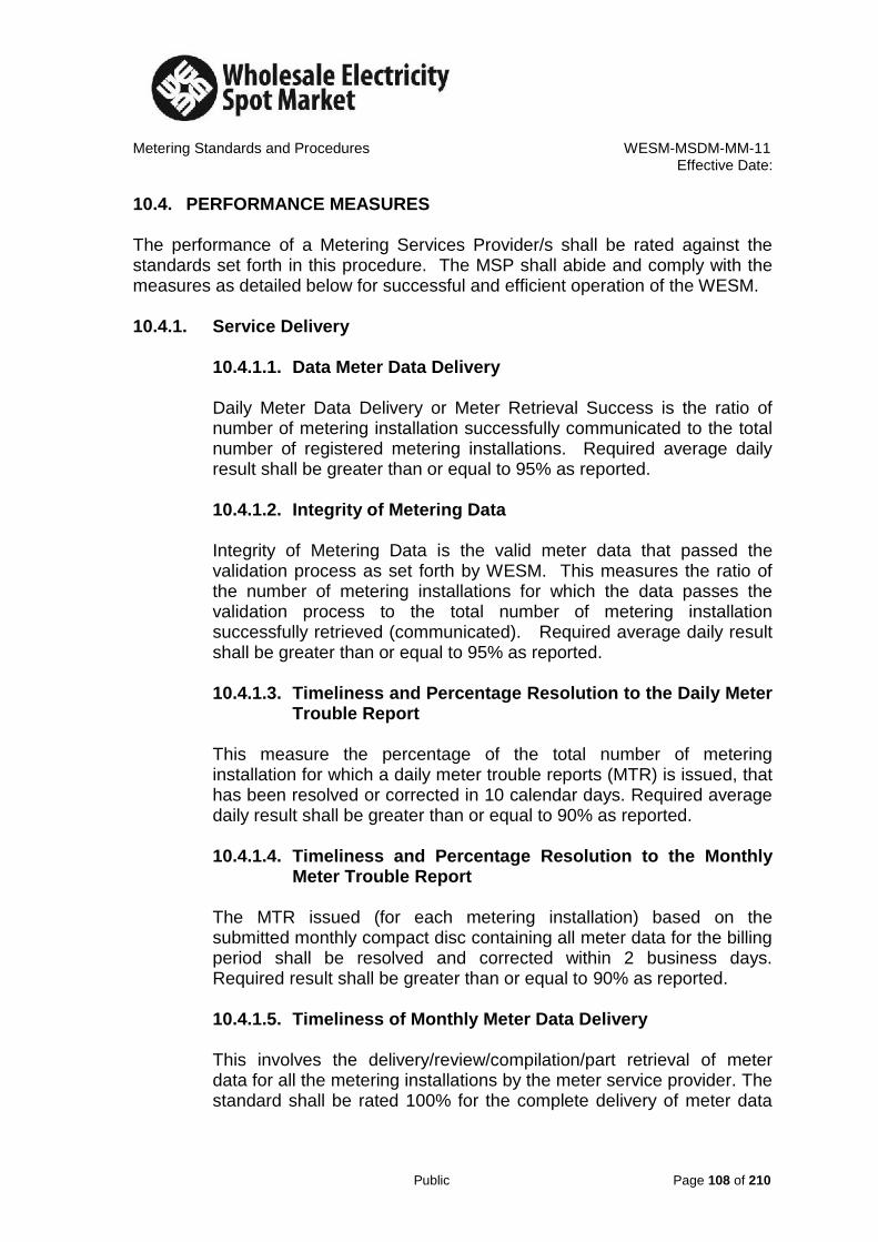
Metering Standards and Procedures WESM-MSDM-MM-11
Effective Date:
Public Page 108 of 210
10.4. PERFORMANCE MEASURES The performance of a Metering Services Provider/s shall be rated against the standards set forth in this procedure. The MSP shall abide and comply with the measures as detailed below for successful and efficient operation of the WESM. 10.4.1. Service Delivery
10.4.1.1. Data Meter Data Delivery Daily Meter Data Delivery or Meter Retrieval Success is the ratio of number of metering installation successfully communicated to the total number of registered metering installations. Required average daily result shall be greater than or equal to 95% as reported. 10.4.1.2. Integrity of Metering Data Integrity of Metering Data is the valid meter data that passed the validation process as set forth by WESM. This measures the ratio of the number of metering installations for which the data passes the validation process to the total number of metering installation successfully retrieved (communicated). Required average daily result shall be greater than or equal to 95% as reported. 10.4.1.3. Timeliness and Percentage Resolution to the Daily Meter
Trouble Report This measure the percentage of the total number of metering installation for which a daily meter trouble reports (MTR) is issued, that has been resolved or corrected in 10 calendar days. Required average daily result shall be greater than or equal to 90% as reported. 10.4.1.4. Timeliness and Percentage Resolution to the Monthly
Meter Trouble Report The MTR issued (for each metering installation) based on the submitted monthly compact disc containing all meter data for the billing period shall be resolved and corrected within 2 business days. Required result shall be greater than or equal to 90% as reported. 10.4.1.5. Timeliness of Monthly Meter Data Delivery This involves the delivery/review/compilation/part retrieval of meter data for all the metering installations by the meter service provider. The standard shall be rated 100% for the complete delivery of meter data

Metering Standards and Procedures WESM-MSDM-MM-11
Effective Date:
Public Page 109 of 210
for all metering installations within 3 calendar days after the billing period. Incomplete Metering Data shall be rated based on the ratio of the number of metering points with meter data submitted to total metering installations as registered in the WESM.
10.4.2. Customer Satisfaction Customer Satisfaction is a measurement of the Meter Service Provider corporate image, its responsiveness to emergency situation and on call meeting/s, the safety/behavior of its personnel and its compliance to the requirement of the metering facilities. A Meter Service Provider Customer Satisfaction Rating Sheet shall be issued to measure the service satisfaction provided by a Meter Service Provider as rated by the WESM trading participant/s. Required annual average result shall be greater than or equal to 90%. 10.5. PERFORMANCE STANDARDS The Performance Standard as set by the WESM is the following:
Performance Indicator
Category Performance Measures
Percent Weight
Percent Passing
Service Delivery
Daily Meter Data Delivery
Number of metering installations successfully retrieved
25 95
Integrity of Meter Data
Meter Data that passed the validation processes
25 95
Timeliness and Percentage Resolution to the Daily Meter Trouble Report
Resolution to the Meter Trouble Report within 10 calendar days
15 90
Timeliness and Percentage Resolution to the
Resolution to the Meter Trouble Report within 2
10 90

Metering Standards and Procedures WESM-MSDM-MM-11
Effective Date:
Public Page 110 of 210
Performance Indicator
Category Performance Measures
Percent Weight
Percent Passing
Monthly Meter Trouble Report
business days
Timeliness of Monthly Meter Data Delivery
Complete delivery of all meter data within 3 calendar days after the billing period.
15 100
Customer Satisfaction
Customer Satisfaction Rating
Meter Service Provider Performance Appraisal by the Trading Participant/s.
10 90
10.6. OVERALL PASSING PERCENTAGE The following is the overall passing percentage of a meter service provider rated annually. % Weight Passing Equivalent %
Daily Meter Data Delivery
25 % 95 % 23.75 %
Integrity of Meter Data
25 % 95 % 23.75 %
Timely Resolution (Daily MTR)
15 % 90 % 13.5 %
Timely Resolution (Monthly MTR)
10 % 90 % 9 %
Timely Delivery Monthly Meter Data
15 % 100 % 15 %
Customer Satisfaction
10 % 90 % 9 %
Overall Passing 94 %

Metering Standards and Procedures WESM-MSDM-MM-11
Effective Date:
Public Page 111 of 210
10.7. PERFORMANCE RATING 10.7.1. Monthly Performance Rating After every billing period, the Philippine Electricity Market Corporation shall issue or release to the trading participant/s and meter service provider/s the actual generated performance rating of the MSP measured under Section 10.4.1 – Service Delivery. The result of the MSP performance ratings shall be discussed with the MSP by the PEMC if so requested by the concerned MSP and its trading participant/s. The generated performance rating of the MSP shall be published in the website. 10.7.2. Semi-Annual Customer Satisfaction Rating Every six (6) months, the PEMC Metering & Settlement Department shall conduct a CSR on the MSP performance through the issuance of the CSR form to all the WESM trading participants to be accomplished and submitted back to PEMC. The CSR forms are to be accomplished every first week of July of the current year and January of the following year. The July rating comprises the MSP performance from January to June of the current year and the January rating correspond to the second half of the previous year (July to December). 10.7.3. Annual Performance Rating Annual Performance Rating covers the billing periods January to December of each year. It shall consist of:
1. The annual Performance Measures under Sub- section 10.4.1 – Service Delivery (Average of the 12 months billing).
2. The Customer Satisfaction Rating under Sub-sections 10.4.2 and 10.7.2.
The annual MSP Performance Rating shall be submitted by the PEMC Metering & Settlement Department to PEMC Management.
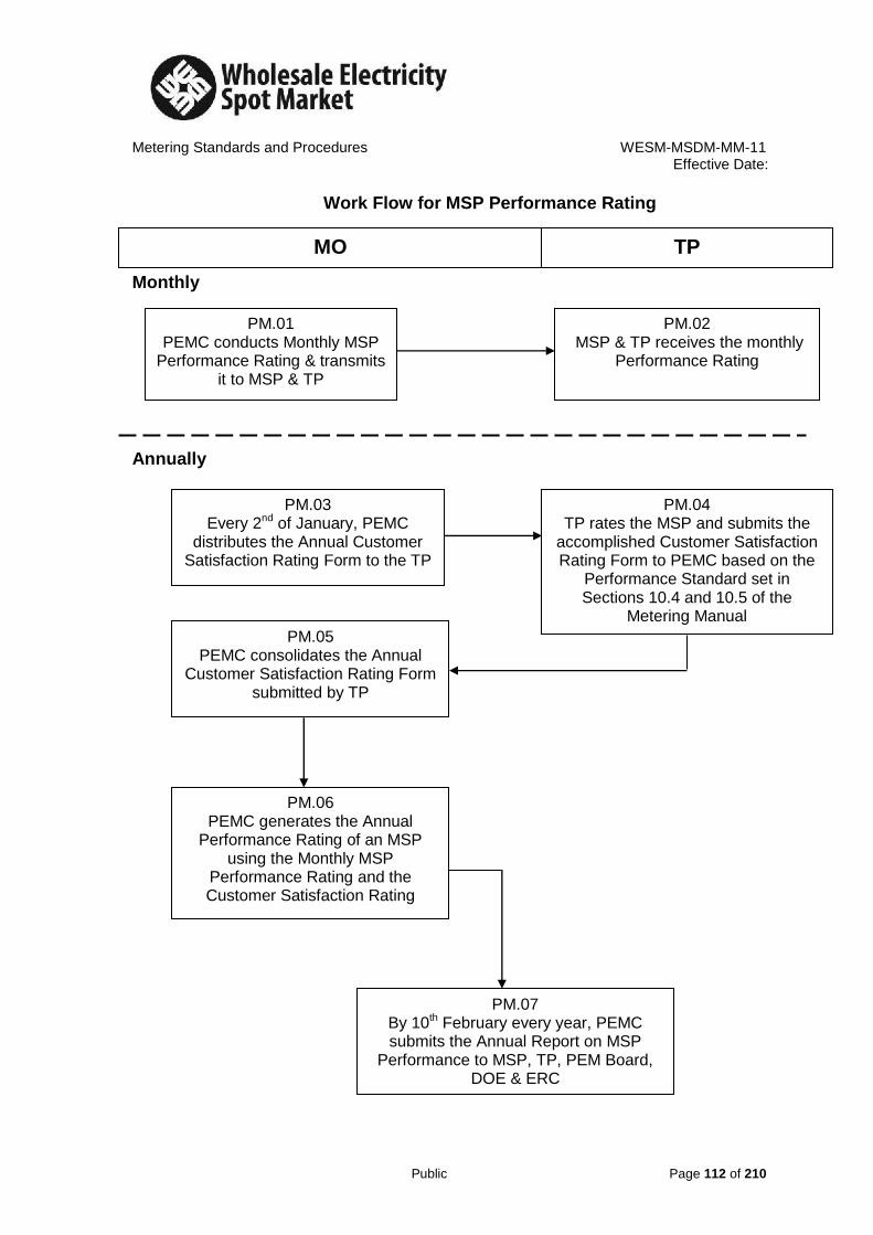
Metering Standards and Procedures WESM-MSDM-MM-11
Effective Date:
Public Page 112 of 210
Work Flow for MSP Performance Rating
Monthly
Annually
MO TP
PM.01 PEMC conducts Monthly MSP
Performance Rating & transmits it to MSP & TP
PM.02 MSP & TP receives the monthly
Performance Rating
PM.03 Every 2nd of January, PEMC
distributes the Annual Customer Satisfaction Rating Form to the TP
PM.04 TP rates the MSP and submits the
accomplished Customer Satisfaction Rating Form to PEMC based on the
Performance Standard set in Sections 10.4 and 10.5 of the
Metering Manual PM.05
PEMC consolidates the Annual Customer Satisfaction Rating Form
submitted by TP
PM.06 PEMC generates the Annual
Performance Rating of an MSP using the Monthly MSP
Performance Rating and the Customer Satisfaction Rating
PM.07 By 10th February every year, PEMC submits the Annual Report on MSP
Performance to MSP, TP, PEM Board, DOE & ERC

Metering Standards and Procedures WESM-MSDM-MM-11 Effective Date:
Public Page 113 of 210
Customer Satisfaction Measurement
Meter Service Provider Customer Satisfaction Rating Sheet: *LEVELS OF SATISFACTION
Below 90% Above 90% Above 95% Above 99%
A. Corporate Image:
Does the MSP’s Company/Employee maintain good representation at all times?
Wearing ID at all times
Tidy and neat appearance/attire of personnel
General appearance of service vehicle
Upkeep of tools and equipment
B. Punctuality/Responsiveness:
Do they arrive/act on time?
Emergency breakdown
On time during appointment/meeting
Do they submit report/s on time? Metering Information Registration Form
Notice of Metering Installation Changes
Metering Equipment Test/Calibration Report/s
C. Safety:
Do they observe safety at all times?
Wearing safety helmet
Wearing safety shoes
Wearing gloves when needed
Secure clearance during metering activities
D. Behavioral/ General Impression
Do they conduct themselves in a professional manner?
Courteous
Accommodating
Knowledgeable/Competent
* MSP Rating in numerical percentage

Metering Standards and Procedures WESM-MSDM-MM-11
Effective Date:
Public Page 114 of 210
APPENDIX
METERING SERVICES PROVIDER REGISTRATION FORM
A. General Information
1. Name
Name of Organization to be Registered: ___________________________ Short Name: ________________________________
2. Business/ Office Address
No. Street City: Province: Postal/Zip Code:
Phone Number: FAX Number: E-mail Address:

Metering Standards and Procedures WESM-MSDM-MM-11
Effective Date:
Public Page 115 of 210
3. Primary Contact for this Application Mr. Mrs. Last Name: Full Name: Middle Initial: Mr. /Ms. ______________________________________________________ Position Held _____________________________________________________ Other: ______________________________________________________ Local Address, if the address in item 2 is located outside the country:
Street City: Province Country Postal/Zip Code:
Phone Number: FAX Number: E-mail Address:
Assistant’s Name: ______________________________________________________ 4. Head of Business Organization (chief executive officer, president or other
person that has authority over and responsibility for the operations of the organization)
Mr. Mrs. Last Name: Full Name: Middle Initial: Miss. Ms. ______________________________________________________ Position Held _____________________________________________________ Other: ______________________________________________________ Phone Number: FAX Number: E-mail Address:

Metering Standards and Procedures WESM-MSDM-MM-11
Effective Date:
Public Page 116 of 210
B. Details of Mo’s Requirements
1. Nature and Details of Form of Applicant’s Business Organization
Form (i.e., corporation, partnership, etc.): _________________________ Date of Information: __________________________________________
2. How long is your organization been involved in the metering services? _________Please submit additional documents as detailed below in support to the registration.
A. Provide proof that it has relevant experience (technical and financial capability) based on previous work and company’s profile on Technical Capability;
a. Submit a detailed list of the company’s employees resume, which contains years of experience and their respective field of expertise;
b. Demonstrate and submit documents that an appropriate infrastructure exists to communicate with the MO for Metering processes;
c. Demonstrate and Submit documents an ability to service meter trouble calls to MO standards; and
d. Demonstrate and Submit documents that emergency restoration plans for Metering Installation failure are in place.
B. Certificate of Authority from the ERC and all relevant documents as approved by ERC.
3. For further clarification, please don’t hesitate to call us at Tel No. 631-87-34 local ____ or e-mail your inquiry at_______
Submitted by:
President or Representative Meter Service Provider

Metering Standards and Procedures WESM-MSDM-MM-11
Effective Date:
Public Page 117 of 210
METERING INSTALLATION FORM
Region Resource ID (for MO use only)
District Market Trading Node (for MO use only)
PARTICIPANT'S INFORMATION
Participant's Name:
Type : Generator Customer
Delivery Pt No./Address Substation Name/Capacity/Loc/Prov.
Voltage Level Classification Type of Meter:
Electronic
Electro-Mechanical
Contact Person Tel. No.
Metering Services Provider Tel. No.
METERING INFORMATION
Scheme MAIN Meter
Multiplier:
Metering Line Voltage Internal External
Service ALT/BACK-UP Meter
Multiplier:
Frequency Internal External
METER DEVICE INFORMATION
Particulars MAIN Meter ALTERNATE/BACK-UP Meter
METERING INSTALLATION (MI) SEIN
Serial Number
Make/Brand
Model/Type
Time Base Used
METER COMMUNICATION INFORMATION
Communication Port/s Available BAUD Rate
Telephone No./Communication Provider Available
Additional Documents to be submitted Remarks (for MO Used Only)
1.) Metering Installation Specifications
2.) Load Profile (Forecast, Historical Data, including Maximum and Minimum Hourly Demand)
3.) Data of Connected Power Transformers (Core & Copper Loss)
PHILIPPINE ELECTRICITY MARKET CORPORATION 9th Floor, Robinsons-Equitable Tower, ADB Ave. cor. Poveda St., Ortigas Center 1600, Pasig City Tel. No. (632) 631-8734 Telefax: (632) 636-0802 Website: www.wesm.ph
PHIL
IPPI
NE
ELEC
TRICITY MARKET C
ORPO
RATIO
N
2 0 0 3

Metering Standards and Procedures WESM-MSDM-MM-11
Effective Date:
Public Page 118 of 210
4.) Data of Lines from Metering Point to Market Trading Node
5.) Drawing of the Location Plan of the Metering Point
6.) Single Line Diagrams from Grid Substation to the Metering Point
7.) Detailed Wiring Diagram of the Metering Installation
8.) ERC's Certification on Meter Test Results (w/ ERC Seal)
9.) Test & Calibration reports of Instrument Transformers and Meters
10.) Pro-forma Agreement between Trading Participant & its MSP
11.) Other Special Features of the Meter
Submitted by: Approved by:
(Signature above Printed Name) Note: The Trading Participant shall accomplished this form in coordination with its MSP All drawings, plans, wiring diagrams shall be signed by a Professional Electrical Engineer.

Metering Standards and Procedures WESM-MSDM-MM-11
Effective Date:
Public Page 119 of 210
GOVERNING PROVISIONS OF THE WESM RULES The following pertinent provision in the WESM rules that served as requirements for potential candidates for being Trading Participants and Metering Services Providers are detailed below, to wit: Section 4.3.2 Election of a Metering Services Provider by a Trading Participant
Section 4.3.2.1 A Trading Participant who is a Direct WESM Member shall: a. Elect a Metering Services Provider who will have
responsibility for arranging for the provision, installation, testing, calibration and maintenance of each Metering Installation for which that Trading Participant is financially responsible;
Sections 4.3.3 Metering Services Provider Obligations
The Metering Services Provider shall:
a. Ensure that its Metering Installations are provided, installed, tested, calibrated and maintained in accordance with this chapter 4, the Grid Code and Distribution Code and all applicable laws, rules and regulations.
b. Ensure that the accuracy of each of its Metering Installations complies with the requirements of chapter 4 and the Grid Code and Distribution Code; and
c. The Metering Services Provider shall provide for remote
monitoring facilities to alert the Market Operator of any failure of any components of the Metering Installation which might affect the accuracy of the metering data derived from that Metering Installation.
Section 4.4.2 Subject to clause 4.3.3.3, a Generation Company or Customer
which is involved in the trading of energy shall not be registered as a Metering Services Provider for any Connection Point in respect of which the metering data relates to its own use of energy.
Section 4.4.3 If a Trading Participant is a Customer and also a Network Service
Provider, the Trading Participant may register as a Metering Services Provider only for Connection Points that it does not own.

Metering Standards and Procedures WESM-MSDM-MM-11
Effective Date:
Public Page 120 of 210
Section 4.5 METERING INSTALLATION Section 4.5.1 Metering Installation Components A Metering Installation shall:
a. Be accurate in accordance with this chapter 4 and the Grid Code and Distribution Code;
b. Have facilities to enable metering data to be transmitted from
the metering installation to the metering database, and be capable of communication with the metering database; This requirement may be relaxed during the operation of the interim WESM.
c. Contain a device which has a visible or an equivalently
accessible display of metering data or which allows the metering data to be accessed and read at the same time by portable computer or other equipment of a type or specification reasonably acceptable to all entities who are entitled to have access to that metering data;
d. Be secure;
e. Have electronic data recording facilities such that all metering
data can be measured and recorded in trading intervals;
f. Be capable of separately registering and recording flows in each direction where bi-directional active energy flows occur;
g. Have a meter having an internal or external data logger
capable of storing the metering data for at least 60 days and have a back up storage facility enabling metering data to be stored for 48 hours in the event of external power failure; and
h. Have an active energy meter, and if required in accordance
with the Grid Code and Distribution Code, a reactive energy meter, having both an internal or external data logger.
Section 4.5.6 Security of Metering Data Held in a Metering Installation
The Metering Services Provider shall ensure that metering data held
in a Metering Installation is protected from local or remote electronic access or manipulation of data by the installation of suitable security

Metering Standards and Procedures WESM-MSDM-MM-11
Effective Date:
Public Page 121 of 210
electronic access controls (including, if required by the Market Operator, passwords).
Section 4.5.7 Performance of Metering Installations
Section 4.5.7.1 The Metering Services Provider shall use all reasonable
endeavors to ensure that metering data is capable of being transmitted to the metering database from its Metering Installations:
a. Within the applicable accuracy parameters described in the
Grid Code and Distribution Code; and
b. Within the time required for settlement, at a level of availability of at least 99% per annum, or as otherwise agreed between the Market Operator and the Metering Services Provider.
Section 4.5.7.2 If a Metering Installation malfunction or defect occurs, the
Metering Services Provider shall ensure that repairs shall be made as soon as practicable and in any event within two business days, unless extended by the Market Operator.
Section 4.5.8 Meter Time
Section 4.5.8.1 The Metering Services Provider shall ensure that all
Metering Installation and data logger clocks are referenced to Philippines Standard Time.
Section 4.6 METERING DATA
Section 4.6.1 Changes to Metering Data The Metering Services Provider shall not make, cause or allow any alteration to the original stored data in a Metering Installation. It shall also use reasonable endeavors to ensure that no other person or entity does the same. Section 4.6.2.3 The Metering Services Provider shall, at its own cost,
ensure that metering data derived from a Metering Installation for which it is responsible shows the time and date at which it is recorded and is capable of being transmitted from the metering installation to the metering database in accordance with the Market Operator’s reasonable requirements.

Metering Standards and Procedures WESM-MSDM-MM-11
Effective Date:
Public Page 122 of 210
Section 4.6.2.5 Without prejudice to the generality of this clause 4.5, the
Metering Services Provider shall ensure that each of its Metering Installations have adequate communication facility that will enable the Market Operator to obtain remote access to the metering data from the metering database. This requirement, however, may be relaxed during the initial operation of the WESM.
Section 4.8.1 Installation Databases
Section 4.8.1.1 The Metering Services Provider shall create, maintain and
administer an installation database in relation to all its Metering Installations.
Section 4.8.1.2 The Metering Services Provider shall ensure that each
affected Participant and the Market Operator is given access to the information in its installation database at all reasonable times and:
a. In the case of data sixteen months old or less, within seven
business days of receiving written notice from the person or entity seeking access; and
b. In the case of data more than sixteen months old, within thirty
days of receiving written notice from the person or entity seeking access.
Section 4.8.1.3 The Metering Services Provider shall ensure that its
installation database contains the information specified in Appendix B2.
Section 4.8.4 Confidentiality
Subject to clause 4.7.3, metering data is confidential and each WESM Member and Metering Services Provider shall ensure that such data is treated as confidential information in accordance with the WESM Rules.

Metering Standards and Procedures WESM-MSDM-MM-11
Effective Date:
Public Page 123 of 210
METERING SERVICE AGREEMENT
This METERING SERVICE AGREEMENT (hereinafter referred to as “Agreement,” for brevity) entered into this ______ day of ___________, 2005, by and between: __________(individual/ corporation/ business organization)_______ duly incorporated/formed/registered] and organized under the laws of __________(country/state) ___________, having its registered address at_________________________________________________________________, hereinafter referred to as the Metered Trading Participant (MTP).
- and -
_____________________________________, a (form of business organization) organized under the laws of the Republic of the Philippines, and having received Authorization from the Philippine Energy Regulatory Commission (ERC) to operate as a Metering Services Provider for WESM Trading Participants, and having its registered address at _____________________________________________________________, hereinafter referred to as the Metering Service Provider ( MSP)
WITNESSETH:
WHEREAS, The provision of metering equipment and services to the entities involved in the generation, transmission, distribution, and wholesale trading of electricity in the restructured Philippine electricity industry is governed by the Wholesale Electricity Spot Market (WESM) Rules, the Philippine Grid Code, and the Philippine Distribution Code;
WHEREAS, Clause 4.3.2 of the WESM Rules requires a Trading
Participant who is a Direct WESM Member to:
(a) Elect a Metering Services Provider who will provide, install, test, calibrate and maintain each metering installation for which the Trading Participant is financially responsible;
(b) Enter into an Agreement with the Metering Services Provider which includes the terms and conditions for the provision, installation and maintenance of the relevant metering installation by the Metering Services Provider, and
(c) Provide the Market Operator with the relevant details of the metering installation in accordance with Appendix B2 within ten (10) business days of entering into an Agreement with the Metering Services Provider(s) under clause 4.3.4(b);
WHEREAS, the WESM Rules requires the Metering Services Provider to:
Met
erin
g S
ervic
es P
rovid
er (
MS
P):
Met
ered
Tra
din
g P
arti
cipan
t (M
TP
):
MS
P R
epre
senta
tiv
e:
M
TP
Rep
rese
nta
tive:
Tit
le:
Sig
na
ture
:
Tit
le:
Sig
nat
ure

Metering Standards and Procedures WESM-MSDM-MM-11
Effective Date:
Public Page 124 of 210
(a) Ensure that its metering installations are provided, installed, tested, calibrated and maintained in accordance with Chapter 4 of this, the Grid Code and Distribution Code and all applicable laws, rules and regulations. (Clause 4.3.3)
(b) Ensure the accuracy of each of its metering installations in compliance with the requirements of Chapter 4 and the Grid Code and Distribution Code.(Clause 4.3.3)
(c) Protect the metering installation from any form of unauthorized interference, by providing secure housing for metering equipment or by ensuring that security at the metering point is adequate to protect against such interference. (Clause 4.5.5.1)
(d) Ensure that metering data held in a metering installation are duly- protected from local or remote electronic access or manipulation of data by the installation of suitable security electronic access controls (including, if required by the Market Operator, passwords). (Clause 4.5.6)
(e) Undertake all reasonable measures to ensure that the metering data are capable of being transmitted to the metering database from their metering installations (Clause 4.5.6):
(f) Perform repairs on failed metering installations as soon as practicable and in any event within two (2) business days, unless extended by the Market Operator (Clause 4.5.7.2);
WHEREAS, The (Name of MSP) has been issued Authorization by the
Energy Regulatory Commission (“ERC”) and registered by the Market Operator (“MO”) as a Metering Service Provider of the WESM, and the (Name of Metered Trading Participant) has been registered by the Market Operator as a WESM Trading Participant;
WHEREAS, The provision and maintenance of revenue metering
equipment, and the delivery of services as Meter Service Provider to the Metered Trading Participants shall be covered in a Supplemental Agreement to this Metering Service Agreement;
WHEREAS, This Agreement is entered into for the purpose of establishing
the terms and conditions between the Parties, as well as their respective rights and obligations pursuant to this Agreement, the WESM Rules, the Grid Code, and the Distribution Code;
NOW, THEREFORE, for and in consideration of the mutual covenants
herein set forth, for valuable and adequate consideration, the receipt of which is hereby acknowledged, the Parties agree as follows:
Me
terin
g S
erv
ices P
rovid
er
(MS
P):
Me
tere
d T
radin
g P
art
icip
an
t (M
TP
):
MS
P R
epre
senta
tive:
M
TP
Re
pre
se
nta
tive
:
Title
:
S
igna
ture
:
Title
:
S
igna
ture

Metering Standards and Procedures WESM-MSDM-MM-11
Effective Date:
Public Page 125 of 210
ARTICLE I
INTERPRETATION
1.1. WESM Rules Definitions: Subject to Section 1.2, italicized expressions used in this Page 2 of 12 Agreement have the meanings ascribed thereto in Chapter 11 of the WESM Rules.
1.2. Supplementary Definitions: The following words shall have the
meanings set out below, unless the context requires otherwise:
“Agreement” means this Agreement, including any Schedules hereto attached; “Metered Trading Participant” (MTP) means a WESM Trading Participant which has contracted the services of a Metering Service Provider (MSP) under this Agreement. "Applicable Laws” are laws, regulations, rules, codes, guidelines, market manuals and such other documents as are applicable to the provision of metering services, and all orders of the government and its instrumentalities and agencies exercising jurisdiction over such activities; “Confidential Information” means (i) information which has been supplied by the disclosing person in confidence implicitly or explicitly, where disclosure can reasonably be expected to (a) prejudice significantly the competitive position of the disclosing person, (b) interfere significantly with the contractual or other negotiations of the disclosing person or another person; (c) result in undue loss or gain to the disclosing person or to another person, (d) compromise the efficiency of the WESM, or (e) result in the disclosing person’s being in breach of a bona fide arm’s length confidentiality agreement to which the information is subject; or (ii) information that, pursuant to the WESM Rules or such other applicable laws, the Parties cannot disclose or make available to one or more persons; “Effectivity Date” is the date of signing of this Agreement by the representatives of the Metering Service Provider (MSP) and the Metered Trading Participant (MTP); "Party" means a party to this Agreement; “Market Operator” means the Philippine Electricity Market Operator or any other successor entity duly formed for the purpose of operating the spot market;
Met
erin
g S
ervic
es P
rovid
er (
MS
P):
Met
ered
Tra
din
g P
arti
cipan
t (M
TP
):
MS
P R
epre
senta
tiv
e:
M
TP
Rep
rese
nta
tive:
Tit
le:
Sig
nat
ure
:
Tit
le:
Sig
nat
ure

Metering Standards and Procedures WESM-MSDM-MM-11
Effective Date:
Public Page 126 of 210
“Supplemental Agreement” is an agreement which is intended to supplement and form part of this Agreement, for the purpose of defining the specific scope of supply and services, the agreed rates for the service charges, and other commercial terms not covered in this Agreement.
1.3. Interpretation: Unless the context otherwise requires, it is understood
that: 1.3.1. Words importing the singular include the plural and vice versa; 1.3.2. Words importing a gender include all genders; 1.3.3. When italicized, the parts of speech and grammatical forms of a
word or phrase defined in this Agreement have a corresponding meaning;
1.3.4. “Person” includes a natural or juridical person; 1.3.5. A reference to a thing includes a part of that thing; 1.3.6. A reference to an article, section, provision or schedule is
understood to mean that which is contained in this Agreement; 1.3.7. A reference to any statute, regulation, proclamation or any
similar directive includes all statutes, regulations, proclamations, orders or directives varying, consolidating, re-enacting, extending or replacing it;
1.3.8. A reference to a document or provision of a document, including this Agreement and the WESM Rules, includes an amendment or supplement to, or replacement or notation of, that document, as well as any exhibit, schedule, appendix or other attachments thereto;
1.3.9. A reference to a person includes that person’s heirs, executors, administrators, successors and permitted assigns;
1.3.10. A reference to sections of this Agreement or of the WESM Rules separated by the word “to” ( i.e., “sections 1.1 to 1.4”) shall be a reference to the sections inclusively;
1.3.11. The expressions “including,” “includes” and “included” mean including, without limitation; and
1.3.12. A reference in this Agreement to the WESM Rules includes a reference to any forms and market manuals pertaining to the WESM and to any policies, guidelines or other documents adopted by the PEM Board;
1.4. Headings: The division of this Agreement into articles and sections and
the insertion of headings are for convenience of reference only and shall not affect the interpretation of this Agreement, nor shall they be construed as indicating that all of the provisions of this Agreement relating to any particular topic are to be found in any particular article, section, sub-section, clause, provision, part or schedule.
Mete
ring S
erv
ices P
rovid
er
(MS
P):
Mete
red T
radin
g P
art
icip
ant (M
TP
):
MS
P R
epre
senta
tive:
M
TP
Re
pre
se
nta
tive
:
Title
:
S
igna
ture
:
Title
:
S
igna
ture

Metering Standards and Procedures WESM-MSDM-MM-11
Effective Date:
Public Page 127 of 210
ARTICLE 2
WESM RULES
2.1. WESM Rules Governs: In the event of any inconsistency between this Agreement and the WESM Rules, the WESM Rules shall prevail.
ARTICLE 3
MSP RIGHTS AND OBLIGATIONS
3.1 Compliance with WESM Rules: The MSP is bound by the provisions of the WESM Rules, the Grid Code and the Distribution Code insofar far as they are applicable to metering service providers in the same manner as if such provisions formed part of this Agreement.
3.2 Provision of Metering Equipment: The MSP shall provide the
equipment that shall form part of the Metering Installation in accordance with the agreed scope of supply under the Supplemental Agreement between the Metering Service Provider and the Metered Trading Participant.
3.3 Provision of Metering Services: The MSP shall provide the following
metering services:
3.3.1 Metering installation and commissioning services for new metering installations or upgrading, relocation or such other services for the purpose of providing WESM compliant meters;
3.3.2 Metering installation operation and preventive maintenance, covering the following activities:
a. Meter reading; b. Periodic inspections; c. Metering security; d. Meter data communications service, including commercial
telephone subscription; e. Annual calibration and testing of meters; f. Testing of instrument transformers as may be provided under
the WESM Rules, furnishing the Metered Trading Participant with metered demand and energy consumption data, metering installation data and such other data as may be required by the MO;
Me
terin
g S
erv
ices P
rovid
er
(MS
P):
Me
tere
d T
radin
g P
art
icip
an
t (M
TP
):
MS
P R
epre
senta
tive:
M
TP
Re
pre
se
nta
tive
:
Title
:
S
igna
ture
:
Title
:
S
igna
ture

Metering Standards and Procedures WESM-MSDM-MM-11
Effective Date:
Public Page 128 of 210
3.3.3 Off-schedule work requested by the Market Operator or the Metered Trading Participant;
3.4 Performance Standards: The MSP shall meet the performance
standards pertaining to its obligations set forth in the ERC Guidelines for MSPs, the WESM Rules, Grid Code & Distribution Code.
3.5 Staffing Requirements: The MSP shall at all times maintain an
adequate number of qualified personnel so as to permit it to perform all of its functions and obligations under this Agreement, and as a Metering Service Provider under the WESM Rules, and to meet the performance standards referred to in Section 3.4.
3.6 Rights Relating to Metering Installations: The Metered Trading
Participant shall, in respect to a metering installation covered under the Supplemental Agreement, provide the MSP with access to, and procure any rights necessary, for the MSP to access such metering installation and to access all metering data in such metering installation to the extent of enabling the MSP to perform its obligations and exercise its rights under the WESM Rules and this Agreement.
3.7 Information on Metering Installation: The MSP shall disclose or
provide to the Metered Trading Participant all information on the metering installation for which it is the Metering Service Provider where such information is required by the Metered Trading Participant in order to be able to perform its obligations and exercise its rights under the WESM Rules and this Agreement with respect to such metering installation. Where no time is specified as regards the disclosure or provision of specific information, the said information shall be disclosed or provided within a reasonable time.
3.8 Accuracy of Information: The MSP shall ensure the accuracy of information it has obtained from its metering installations.
3.9 Correction of Information: Where the MSP discovers that any
information previously disclosed by it pursuant to Section 3.7 was untrue or inaccurate, or subsequently becomes untrue, incorrect, incomplete, misleading or deceptive, the MSP shall immediately rectify the situation by disclosing or providing the true, correct, complete and accurate information to the person to whom the erroneous information was disclosed or provided.
3.10 Record Retention: The MSP shall retain all records which it is
mandated to maintain as per the provisions of Chapter 4 of the WESM Rules, or as per the order of the Metered Trading Participant under this Agreement for a period of sixteen (16) months in accessible format, and
Mete
ring S
erv
ices P
rovid
er
(MS
P):
Mete
red T
radin
g P
art
icip
ant (M
TP
):
MS
P R
epre
senta
tive:
M
TP
Re
pre
se
nta
tive
:
Title
:
S
igna
ture
:
Title
:
S
igna
ture

Metering Standards and Procedures WESM-MSDM-MM-11
Effective Date:
Public Page 129 of 210
ten (10) years in archive, or for such other period of time as may be specified in the WESM Rules or designated by the MO in respect of any record or class of records.
3.11 Permits and Licenses: The MSP shall at all times maintain in good
standing all permits, licenses and other authorizations that may be necessary to enable it to carry on the business, and perform the functions and obligations of a Metering Service Provider as described in the WESM Rules and in this Agreement.
3.12 Notification of Significant Events: The MSP shall notify the Metered
Trading Participant of any of the circumstances which may give rise to the following, either at the time of the occurrence thereof, or immediately upon becoming aware thereof:
3.12.1 The MSP ceases to satisfy any of the qualifications of an MSP. 3.12.2 It becomes unlawful for the MSP to comply with any of the
obligations imposed on Metering Service Providers under the WESM Rules or under this Agreement by reason of the fact that its license, permit or other authorization has been suspended or revoked.
3.12.3 The MSP ceases, or is in danger of terminating, the conduct of its business or a substantial part thereof;
3.12.4 The MSP is wound up or dissolved, unless the notice of winding up or dissolution is discharged;
3.12.5 The MSP is insolvent or unable to pay its debts under any applicable legislation;
3.12.6 An event has triggered, or is likely to trigger, the revocation or expiration of the registration of any metering installation with respect to which it acts as a metering service provider; and
3.12.7 Any other event arises which materially affects or is likely to materially affect: a. the performance by the MSP of any of the obligations
imposed on Metering Service Providers under the WESM Rules or this Agreement;
b. the performance by the MSP of its obligations relating to metering installations or metering data under the WESM Rules or this Agreement; or
c. the performance, accuracy or security of any metering installation with respect to which it acts as a Metering Service Provider or of any metering data contained in, or are being made available from such metering installation.
3.13 No Adjustments to Metering Data: Except as expressly permitted by
the WESM Rules or this Agreement, the MSP shall not adjust any
Me
terin
g S
erv
ices P
rovid
er
(MS
P):
Me
tere
d T
radin
g P
art
icip
an
t (M
TP
):
MS
P R
epre
senta
tive:
M
TP
Re
pre
se
nta
tive
:
Title
:
S
igna
ture
:
Title
:
S
igna
ture

Metering Standards and Procedures WESM-MSDM-MM-11
Effective Date:
Public Page 130 of 210
metering data or other information contained in a metering installation with respect to which it is the Metering Service Provider, in the metering registry or in the metering database.
3.14 Insurance: The MSP shall at all times maintain general contractual
liability insurance coverage and such other insurance coverage upon such terms and in such amounts as would be maintained by a prudent person conducting business activities identical to, or similar in nature, to those of the MSP’s.
3.15 The MSP as a Third-Party Beneficiary. The MSP shall be a third-party
beneficiary to any future agreement between the Metered Trading Participant and any other party relating to the metering installation of the Metered Trading Participant for the purpose of granting the MSP access to any relevant information, records and facilities as needed by the MSP to fulfill its obligations under the WESM Rules, the Grid Code, Distribution Code, and this Agreement.
ARTICLE 4
RIGHTS AND OBLIGATIONS OF METERED TRADING PARTICIPANTS
4.1 Compliance with WESM Rules: The Metered Trading Participant is bound by the provisions of the WESM Rules insofar as they are applicable to the subject matter of this Agreement as though such provisions formed part of this Agreement.
4.2 Provision of Metering Equipment. The Metered Trading Participant
shall provide the metering equipment to be installed as part of the Metering Installation;
4.3 Payment for Metering Charges. The Metered Trading Participant shall
pay to the Metering Services Provider the metering charges as stipulated in the Supplemental Agreement, to cover the following items of supply and services:
4.3.1 Metering Installation and Commissioning Services, as one-time
charge. 4.3.2 Metering Installation Operation and Preventive Maintenance, as
regular monthly charge, covering the costs of: a. Meter reading; b. Periodic inspections; c. Metering security;
Me
terin
g S
erv
ices P
rovid
er
(MS
P):
Me
tere
d T
radin
g P
art
icip
an
t (M
TP
):
MS
P R
epre
senta
tive:
M
TP
Re
pre
se
nta
tive
:
Title
:
S
igna
ture
:
Title
:
S
igna
ture

Metering Standards and Procedures WESM-MSDM-MM-11
Effective Date:
Public Page 131 of 210
d. Meter data communications service, including commercial telephone subscription;
e. Annual calibration and testing of meters; f. Testing of instrument transformers as may be provided under
the Grid Code.
4.3.3 Capital Cost Recovery for metering equipment provided by the Metering Service Provider, as part of its scope of supply under the Supplemental Agreement, to be paid as part of the monthly metering charges.
4.3.4 Off-schedule work rendered as per request of the Trading
Participant, to be paid as part of the monthly metering charges.
4.3.5 Miscellaneous expenditures including replacement of metering equipment, and costs arising from any compliance to regulatory requirements under the WESM Rules, Grid Code, Distribution Code and other applicable laws.
The rates covering these charges and the manner in which the amounts shall be computed shall be covered by the Supplemental Agreement.
4.4 Disclosure of Information: The Metered Trading Participant shall
disclose or provide to the MSP such information as is required to be disclosed or provided to the MSP pursuant to the WESM Rules and this Agreement. Such information shall be so disclosed within the time specified in, and in the form and manner required by the WESM Rules or this Agreement. Where no time is specified in relation to the disclosure or provision of specific information, the same shall be disclosed or provided within a reasonable time.
4.5 Accuracy of Information: Information disclosed or provided by the
Metered Trading Participant pursuant to Section 4.3 shall be true, accurate and complete, to the best of the Metered Trading Participant’s knowledge, at the time when such disclosure or provision is made. The Metered Trading Participant shall not knowingly or recklessly disclose or provide information pursuant to Section 4.3 that, at the time and in light of the circumstances in which such disclosure or provision is made, is misleading or deceptive or does not state a fact that is required to be stated.
4.6 Correction of Information: Where the Metered Trading Participant
discovers that any information previously disclosed or provided by it to the MSP pursuant to Section 4.3 was, at the time of disclosure or subsequently thereafter, becomes untrue, incorrect, incomplete,
Me
terin
g S
erv
ices P
rovid
er
(MS
P):
Me
tere
d T
radin
g P
art
icip
an
t (M
TP
):
MS
P R
epre
senta
tive:
M
TP
Repre
senta
tive:
Title
:
S
igna
ture
:
Title
:
S
igna
ture

Metering Standards and Procedures WESM-MSDM-MM-11
Effective Date:
Public Page 132 of 210
misleading or deceptive, the Metered Trading Participant shall immediately rectify the situation and disclose or provide the true, correct, complete information to the person to whom the original or currently untrue, incorrect, incomplete, misleading or deceptive information had been disclosed or provided.
4.7 Use of Information: Except as otherwise prohibited by the WESM Rules
or this Agreement, the Metered Trading Participant is entitled to use any data or information obtained from the MSP in pursuance of its duties under the WESM Rules or under this Agreement.
4.8 Rights of the MSP to Access Metering Facilities. The Metered
Trading Participant shall, with respect to a metering installation, provide the MSP with access to, and procure any rights necessary for the MSP to access, such metering installation and to access all metering data in such metering installation so as to enable the MSP to perform its obligations and exercise its rights under the WESM Rules and this Agreement. The MSP shall not be prevented from fulfilling its obligations under the WESM Rules and the Grid Code or this Agreement by reason of the fact that it is provided with escorted access to the Metering Facilities of the Metered Trading Participant.
4.9 Notification of Significant Events: The Metered Trading Participant
shall notify the MSP of the occurrence of any circumstance which would most likely give rise to any of the following events, upon the occurrence thereof, or upon becoming aware thereof:
4.9.1 The Metered Trading Participant ceases to satisfy any of the
qualifications of a WESM Trading Participant. 4.9.2 Its registration as a Metered Trading Participant is suspended or
revoked, or is threatened to be suspended or revoked because of violation of the WESM Rules.
4.9.3 The Metered Trading Participant enters into, or intends to enter into an arrangement or compromise with, or an assignment for the benefit of, all or any class of its creditors or members or a moratorium involving any of them;
4.9.4 A receiver, manager or person having a similar function under the laws of any relevant jurisdiction is appointed with respect to any property of the Metered Trading Participant which is used in or relevant to the performance by the MTP of any of the obligations to metering service providers under the WESM Rules or under this Agreement;
4.9.5 An administrator, liquidator, trustee in bankruptcy or person having a similar or analogous function under the laws of any
Mete
ring S
erv
ices P
rovid
er
(MS
P):
Mete
red T
radin
g P
art
icip
ant (M
TP
):
MS
P R
epre
senta
tive:
M
TP
Re
pre
se
nta
tive
:
Title
:
S
igna
ture
:
Title
:
S
igna
ture

Metering Standards and Procedures WESM-MSDM-MM-11
Effective Date:
Public Page 133 of 210
relevant jurisdiction is appointed in respect of the MTP, or any action is taken to appoint such person;
4.9.6 An application is made, or a resolution is passed, for the winding up or dissolution of the MTP;
4.9.7 The MTP is wound up or dissolved, unless the notice of winding up or dissolution is discharged;
4.9.8 The MTP is taken to be insolvent or unable to pay its debts under any applicable legislation;
4.10 The MSP as Third-Party Beneficiary. The Metered Trading Participant
shall ensure that the MSP is given third-party beneficiary rights in any future agreement between the Metered Trading Participant and any other party relating to the metering installations for which it is the MSP, for the purpose of granting the MSP access to any relevant information, records and facilities as needed by the MSP to fulfill its obligations under the WESM Rules, the Grid Code, the Distribution Code, and this Agreement.
ARTICLE 5
REPRESENTATIONS AND WARRANTIES
5.1 Representations and Warranties of the Parties: The Parties to this Agreement hereby represent and warrant as follows :
5.1.1 This Agreement constitutes a legal, binding and enforceable
obligation of the Parties; 5.1.2 The Parties have all the qualifications and none of the
disqualifications to enter into this Agreement; 5.1.3 Each Party has the necessary corporate power to enter into, and
perform its obligations under, this Agreement; 5.1.4 5.1.4 The execution, delivery and performance of this Agreement
has been duly authorized by the government; 5.1.5 The individuals executing this Agreement and any document in
connection herewith have been duly authorized to execute this Agreement and have the full power and authority to bind the Parties;
5.1.6 The activities undertaken by the Parties prior to the effectivity date in respect of any metering installation, have been carried out in accordance with the WESM Rules
Mete
ring S
erv
ices P
rovid
er
(MS
P):
Mete
red T
radin
g P
art
icip
ant (M
TP
):
MS
P R
epre
senta
tive:
M
TP
Re
pre
se
nta
tive
:
Title
:
S
igna
ture
:
Title
:
S
igna
ture

Metering Standards and Procedures WESM-MSDM-MM-11
Effective Date:
Public Page 134 of 210
ARTICLE 6
CONFIDENTIALITY
6.1 Confidentiality: Section 4.8.4 of Chapter 4, and Sections 5.2 - 5.3 of Chapter 5 of the WESM Rules apply to this Agreement, and all references in those Sections to a trading participant are deemed to be references to the MSP and all references in those sections to the WESM Rules are deemed to include references to this Agreement.
6.2 Other Confidentiality Obligations: The MSP shall:
6.2.1 Comply with the obligations referred to in Article 6.1 of this
agreement with respect to any historical metering data pertaining to any metering installation that was created prior to the commencement by the MSP of its activities as a metering service provider; and
6.2.2 Respect the confidentiality classification and all associated restrictions on disclosure, assigned or applicable to any confidential information that the MSP may prepare or have in its possession or control as a result of activities undertaken by the MSP under the WESM Rules or this Agreement.
6.3 Other Confidentiality Provisions: Nothing in this Agreement shall
require a Party to disclose information that it is strictly classified or considered to be highly-confidential by applicable laws or the WESM Rules.
ARTICLE 7
TERM AND TERMINATION
7.1 Term: This Agreement shall be a binding obligation on its date of effectivity and shall remain in full force and effect until terminated in accordance with Sections 7.02 and 7.3 of Article 7.
7.2 Termination upon Revocation of Registration: This Agreement shall
be automatically terminated upon the revocation by the Market Operator of the registration of the Metering Service Provider (MSP) or the Metered Trading Participant (MTP), in accordance with the WESM Rules.
7.3 Termination by any of the Parties: Any of the Parties may terminate
this Agreement with or without cause, within thirty (30) days from written notice to the other party.
Me
terin
g S
erv
ices P
rovid
er
(MS
P):
Me
tere
d T
radin
g P
art
icip
an
t (M
TP
):
MS
P R
epre
senta
tive:
M
TP
Re
pre
se
nta
tive
:
Title
:
S
igna
ture
:
Title
:
S
igna
ture

Metering Standards and Procedures WESM-MSDM-MM-11
Effective Date:
Public Page 135 of 210
7.4 Termination by the MTP Without Cause. Upon termination by the MTP without cause, the MTP shall pay MSP a termination fee in the amount provided for under the Supplemental Agreement.
7.5 Ongoing Liability: Notwithstanding the termination of this Agreement for
any reason, both the Metering Service Provider and Trading Participant shall remain subject to the liabilities and financial obligations that were incurred or which arose under the WESM Rules or this Agreement prior to the date of termination of this Agreement, regardless of the date on which any claim relating thereto may be made.
7.6 Survival: The provisions of Articles 7.4, 6 and 8 of this Agreement shall
survive the termination of this Agreement for any reason.
ARTICLE 8
LIABILITY
8.1 Liability: The provisions of Clauses 2.8 and 4.7 of the WESM Rules or such other applicable laws are incorporated in this Agreement, such that any reference in such Section to metering service providers and trading participants is deemed to be a references to the parties to this Agreement.
ARTICLE 9
DISPUTE RESOLUTION
9.1 Dispute Resolution: In the event of any dispute between the Parties arising pursuant to this Agreement, the Parties shall use the dispute resolution process set forth in Chapter 7 of the WESM Rules. For this purpose, references in Chapter 7 of the WESM Rules to a trading participant shall be deemed to be in reference to the Parties.
9.2 No Other Proceedings: Subject to Section 9.3 of this Agreement, no
Party shall commence a civil action or other proceeding in relation to a dispute referred to in Section 9.1 until such time that the dispute resolution process has been completed.
9.3 No Prejudice to Sanctions: Nothing in this Agreement shall prejudice
the right of the MO to take any enforcement actions referred to in the WESM Rules.
Me
terin
g S
erv
ice
s P
rovid
er
(MS
P):
Me
tere
d T
radin
g P
art
icip
an
t (M
TP
):
MS
P R
epre
senta
tive:
M
TP
Re
pre
se
nta
tive
:
Title
:
S
igna
ture
:
Title
:
S
igna
ture

Metering Standards and Procedures WESM-MSDM-MM-11
Effective Date:
Public Page 136 of 210
ARTICLE 10
MISCELLANEOUS
10.1 Amendment: No amendment of this Agreement shall be effective unless made in writing and signed by the Parties.
10.2 Assignment: Either Party may assign or transfer any or all of its rights
and/or obligations under this Agreement subject to the other Party’s prior written consent. Such consent shall not be unreasonably withheld. Any such transfer or assignment shall be conditioned upon the successor-in-interest’s being pre-qualified to discharge the functions and obligations of the original Party, and its/his full and unconditional acceptance of the rights and obligations under this Agreement, as though said successor-in-interest was an original Party to this Agreement.
10.3 Successors and Assigns: This Agreement shall inure to the benefit of,
and be binding upon, the Parties and their respective heirs, administrators, executors, successors and permitted assigns.
10.4 Further Assurances: Each Party shall promptly execute and deliver or
cause to be executed and delivered all further documents in connection with this Agreement that the other Party may reasonably require for purposes of giving effect to this Agreement.
10.5 Waiver: A waiver of any default, breach or non-compliance under this Agreement shall not take effect, unless in writing and signed by the Party to be bound by the waiver. No waiver shall be inferred or implied from any Party’s failure to act, or delay in acting with respect to the other Party’s default, breach, omission or non-observance of duties and obligations set forth in this Agreement.
10.6 Applicable Laws: The Parties to this Agreement shall ensure
compliance with existing laws, rules, regulations, administrative orders and policies. Any amendments thereto shall be deemed incorporated herein. Should any provision of this Agreement be later on adjudged as unconstitutional, invalid or unenforceable, the same shall be deemed severed here from, without affecting the validity or enforceability of the remaining provisions.
10.7 Prior Agreements: Subject to Article 10.9, this Agreement supersedes
any prior agreement between the Parties.
10.8 Ongoing Liability: Nothing in this Agreement shall extinguish any liabilities or financial obligations that either Party may owe to the other
Me
terin
g S
erv
ices P
rovid
er
(MS
P):
Me
tere
d T
radin
g P
art
icip
an
t (M
TP
):
MS
P R
epre
senta
tive:
M
TP
Re
pre
se
nta
tive
:
Title
:
S
igna
ture
:
Title
:
S
igna
ture

Metering Standards and Procedures WESM-MSDM-MM-11
Effective Date:
Public Page 137 of 210
under the terms of any prior written agreement between them of like intent.
10.9 Notices: Any notice, demand, consent, request or other communication required or permitted to be given or made under this Agreement shall:
10.9.1 Be given or made in the manner set forth in Clause 9.6 of the
WESM Rules; 10.9.2 Be, pursuant to Article 3.11 hereof, addressed to the other Party
in accordance with the information set forth in Part A of Schedule 1; and
10.9.3 Be treated as having been duly given or made in accordance with the provisions of Clause 9.6 of the WESM Rules.
Either Party may change its address and representative as set forth in Part A of Schedule 1 by written notice to the other Party. Such change, however, shall not constitute an amendment of this Agreement for the purposes of the application of Section 10.2.
10.10 Governing Law: This Agreement shall be governed by, and construed
in accordance with, applicable Philippine laws and jurisprudence. 10.11 Counterparts: This Agreement may be executed in any number of
counterparts, each of which shall be deemed to be an original and all of which, when taken together, shall be deemed to constitute one and the same instrument. Counterparts may be executed either in original or faxed form and the Parties adopt any signatures received by a receiving facsimile machine as original signatures of the Parties; provided, however, that any Party providing its signature in such manner shall promptly forward to the other Party an original signed copy of this Agreement which was so faxed. .
Mete
ring S
erv
ices P
rovid
er
(MS
P):
Mete
red T
radin
g P
art
icip
ant (M
TP
):
MS
P R
epre
senta
tive:
M
TP
Re
pre
se
nta
tive
:
Title
:
S
igna
ture
:
Title
:
S
igna
ture

Metering Standards and Procedures WESM-MSDM-MM-11
Effective Date:
Public Page 138 of 210
IN WITNESS WHEREOF, the Parties have hereto executed this Agreement, through their duly authorized representatives.
Metering Service Provider (MSP) Metered Trading Participant (MTP) By: By: Name: Name: Title: Title: Date: Date: _____________________ ____________________
Signature Signature

Metering Standards and Procedures WESM-MSDM-MM-11
Effective Date:
Public Page 139 of 210
METERING OUTAGE FORM
Metering Outage Reporting Form
Form Completion Date:
MTP Name:
MTP ID:
MTP Primary Contact Person/Phone#:
MTP Alternate Contact Person/Phone#:
Facility Name:
Meter Point ID’s Affected:
Power System Outage Yes/No:
Metering Outage Yes/No:
Actual Outage Start Date:
Actual Outage Start Time:
Actual Outage End Date:
Actual Outage End Time:
Temporary Metering Required:
Outage Verification
MTR Numbers:
Remarks: Initial Findings within 24 hours
What causes the problem?
Remedial Action Taken
Note: Detailed Report for submission within 48 Hours to MO.
MTR Closed:
MTR Close Date:
Meter Service Provider of TP
Signature above printed name

Metering Standards and Procedures WESM-MSDM-MM-11
Effective Date:
Public Page 140 of 210
Instructions to MTPs for completion of Metering Outage Form
This form will be used by your MSPs to resolve issued MTRs. This will reduce the time spent by your MSPs in confirming metering outages and the associated costs.
1) MTPs should complete the top portion only (MSP Metering Outage Reporting
Form - Notification). This form should be completed on the start day of the metering outage. Please ensure all meter points affected are included.
2) If the outage is complete enter the end time. 3) Submit the form to your MSPs with a copy to the MO for reference purposes. 4) If the outage is ongoing, complete the end time on day of completion and
resubmit form to your MSPs. 5) The Outage Verification section is for the MSPs only.

Metering Standards and Procedures WESM-MSDM-MM-11
Effective Date:
Public Page 141 of 210
METER TROUBLE REPORT FORM
____________________________ __________________________
Market Operator Meter Service Provider (Signature over Printed Name) (Signature over Printed Name)
Meter Trouble Report Form Completion Date (mm/dd/yyyy):
SEIN:
MDEF File Number:
Substation:
Initial Findings (Gap/Overlap/Uncertain):
Actual Start Date (mm/dd/yyyy):
Actual Start Time (hh:mm):
Actual End Date (mm/dd/yyyy):
Actual End Time (hh:mm):
Initial Action Taken(Edit/Estimation):
MSP Verification Remarks (Findings and Action Taken):
Proposed Adjustment (Estimated Value):
Report Close Date (mm/dd/yyyy):
Note: Detailed Completion Report for submission within 48 Hours to MO.

Metering Standards and Procedures WESM-MSDM-MM-11 Effective Date:
Public Page 142 of 210
METERING INSTALLATION STANDARDS
Table 1 – Standard Burdens for Current Transformers
with 5 A Secondary Windings
Desig- nation
Resistance (ohms)
Inductance (mH)
Impedance (ohms)
Voltamperes (at 5 A)
Power Factor
B-0.1 0.09 0.116 0.1 2.5 0.9
B-0.2 0.18 0.232 0.2 5.0 0.9
B-0.5 0.45 0.580 0.5 12.5 0.9
B-0.9 0.81 1.040 0.9 22.5 0.9
B-1.8 1.62 2.080 1.8 45.0 0.9
Table 2 – Basic Impulse Insulation Levels (BIL)
Nominal System Voltage (kV) BIL and full-wave crest (kV)
15 110
25 150
34.5 200
69 350
115 550
138 650
230 1050
500 1675
Table 3 – Creepage Distance
Pollution Level Minimum Nominal Specific Creepage Distance Between Phase and Earth (mm/kV)
Light 16
Medium 20
Heavy 25
Very Heavy 31

Metering Standards and Procedures WESM-MSDM-MM-11 Effective Date:
Public Page 143 of 210
Table 4 – Standard Burdens for Voltage Transformers
Characteristics on Standard Burdens
Characteristics on 120 V Basis
Characteristics on 69.3 V Basis
Designa- Tion
VA Power Factor
Resis- tance
Induc- tance
Impe- dance
Resis- tance
Induc- tance
Impe-dance
W 12.5 0.10 115.2 3.0400 1152 38.4 1.0100 384
X 25.0 0.70 403.2 1.0900 576 134.4 0.3640 192
M 35.0 0.20 82.3 1.0700 411 27.4 0.3560 137
Y 75.0 0.85 163.2 0.2680 192 54.4 0.0894 64
Z 200.0 0.85 61.2 0.1010 72 20.4 0.0335 24
ZZ 400.0 0.85 30.6 0.0503 36 10.2 0.0168 12
Table 5 – Ratios and Ratings of Voltage Transformers
Rated Voltage (V) Marked Ratio Secondary Voltage
14,400 Grd Y/8,400 70/120:1 120V/69V
24,940 Grd Y/14,400 120/200:1 120V/69V
34,500 Grd Y/20,125 175/300:1 120V/69V
69,000 Grd Y/40,250 350/600:1 115V/67V
115,000 Grd Y/69,000 600/1000:1 115V/67V
138,000 Grd Y/80,500 700/1200:1 115V/67V
230,000 Grd Y/138,000 1200/2000:1 115V/67V
500,000 Grd Y/287,500 2500/4500:1 115V/67V
Table 6 – Minimum Clearances and Distances
CLEARANCES OF ENERGIZED METAL PARTS ARE SUMMARIZED IN THE FOLLOWING TABLE FOR THE DIFFERENT SYSTEMS:
Nominal System Voltage
d1 (mm)
d2 (mm)
D (mm)
H (mm)
13.8 300 350 900 3500
34.5 500 610 1500 3600
69 800 900 2000 3750
115 1100 1360 2500 4000
138 1300 1800 3000 4000
230 1850 3200 4000 5000
500 3250 5200 8000 9000

Metering Standards and Procedures WESM-MSDM-MM-11 Effective Date:
Public Page 144 of 210
Where: d1 = minimum clearance between live metal parts and ground d2 = minimum clearance between live metal parts of two phases D = practical distance phase center lines H = minimum height of live conductors above ground.
However, the upper edge of an earthed insulator support must, for all voltage series, beat a height of at least 2300mm above the ground level.

Metering Standards and Procedures WESM-MSDM-MM-11 Effective Date:
Public Page 145 of 210
Table 7 – Minimum Height and Protective Barrier Clearance in Outdoor Installation
Rated Volta
ge
Maximum
Voltage for Eqpt
Minimum Clearances
Minimum Height Protective Clearance Between Barriers and Live Parts Inside
the Installation At The Perimeter Fence
H A B C D E
Minimum Clearances
Minimum Clearances
Minimum Clearances
Minimum Clearances
Minimum Clearances
Minimum Clearances
Un (kV)
Um (kV)
N (mm) S(mm) N(mm) S(mm) N(mm) S(mm) N(mm) S(mm) N(mm) S(mm) N(mm) S(mm
)
N(mm) S(mm)
3 3.6 150 150 2600 2600 150 150 250 250 600 600 1150 1150 1650 1650
6 7.2 150 150 2600 2600 150 150 250 250 600 600 1150 1150 1650 1650
10 12 150 150 2600 2600 150 150 250 250 600 600 1150 1150 1650 1650
20 24 215 160 2600 2600 215 160 315 600 600 1215 1160 1720 1660
30 36 325 270 2625 2600 325 270 425 625 600 1325 1270 1825 1770
45 52 520 2820 520 620 820 1520 2020
60 72.5 700 3000 700 800 1000 1700 2200
110 123 1100 950 3400 3250 1100 950 1200 1450 1250 2100 1950 2600 2450
150 170 1550 1350 3850 3650 1550 1350 1650 1850 1650 2550 2350 3050 2850
220 245 2200 1850 4500 4150 2200 1850 2300 2500 2150 3200 2850 3700 3350
330 362 2400 4700 2400 2500 2700 3400 3900
380 420 2900 5200 2900 3000 3200 3900 4400
500 525 4100 6400 4100 4200 4400 5100 5600

Metering Standards and Procedures WESM-MSDM-MM-11 Effective Date:
Public Page 146 of 210
DRAWINGS, FIGURES & PERTINENT SKETCHES
Figure 1 – CT/VT Secondary Terminal Box

Metering Standards and Procedures WESM-MSDM-MM-11 Effective Date:
Public Page 147 of 210
Figure 2 - Location/Arrangement of Instrument Transformers

Metering Standards and Procedures WESM-MSDM-MM-11 Effective Date:
Public Page 148 of 210
A – TOWER PLAN (TOP VIEW)
B – TOWER PLAN (DISTANCE BETWEEN PHASES)

Metering Standards and Procedures WESM-MSDM-MM-11 Effective Date:
Public Page 149 of 210
C – TOWER PLAN (DISTANCE BETWEEN INSTRUMENT TRANSFORMERS)
Figure 3 – Distance and Clearance between Instrument Transformers

Metering Standards and Procedures WESM-MSDM-MM-11 Effective Date:
Public Page 150 of 210
Figure 4 – Conduit System

Metering Standards and Procedures WESM-MSDM-MM-11 Effective Date:
Public Page 151 of 210
Figure 5 – Meter Enclosure
Figure 6 – Switch Box

Metering Standards and Procedures WESM-MSDM-MM-11 Effective Date:
Public Page 152 of 210
Figure 7 – Perimeter Fence

Metering Standards and Procedures WESM-MSDM-MM-11 Effective Date:
Public Page 153 of 210
SITE EQUIPMENT IDENTIFICATION (SEIN)
RELEVANT TABLES
Table 8 – Meter Purpose Designation
Designation Meter Purpose
M Main Meter
A Alternate Meter (Partial Redundant Metering)
B Alternate Meter (Full Redundant Metering)
C Check Meter
Table 9 – Site Initials
Generating Stations/ Sub-Stations
Proposed Site ID
Generating Stations/ Sub-Stations
Proposed Site ID
ABAGA ABA ATOK ATO
ABUBOT ABU AURORA AUR
ABUCAY ABC BABATNGON BAB
ABUYOG ABY BACMAN BAC
AGOO AGO BACNOTAN BCN
AGUS AGU BACOLOD BCL
AGUSAN AGS BADOC BAD
AHEP AHE BAGAC BAG
AKLE AKL BAGANGA BGN
ALCEM ALC BAGO BGZ
ALCOY ALY BAIS BAI
ALICIA ALI BAKUN BAK
ALIJIS ALJ BALANGA BAL
ALLEN ALL BALAOAN BLN
ALSONS ALS BALASAN BLS
AMBAGO AMB BALATOC BLT
AMBUKLAO AMK BALDOZA BLD
AMLAN AML BALER BLR
AMPAYON AMP BALIBAGO BLB
AMPUCAO AMC BALIGATANHEP BLG
ANGAT ANG BALINGOAN BNG
ANGELES ANL BALINTAWAK BLK
ANISLAGAN ANI BALIWAG BLW

Metering Standards and Procedures WESM-MSDM-MM-11 Effective Date:
Public Page 154 of 210
Generating Stations/ Sub-Stations
Proposed Site ID
Generating Stations/ Sub-Stations
Proposed Site ID
APALIT APA BALIWASAN BWS
API API BALOC BLC
APLAYA APL BALOIAIRPORT BLP
ARANETA ARA BANGUED BAN
ARHEP ARH BANI BNI
ASTURIAS AST BANILAD BNL
ATIMONAN ATI BANTAY BNT
BANTIGUE BTG BUSECO BUS
BARIT BAR BUTUAN BUT
BAROBO BRB CABACUNGAN CAB
BATAAN BAT CABADBARAN CBD
BATANGAS BTN CABAGAN CBG
BATOBALANI BTB CABANATUAN CBN
BAUANG BAU CABARROGUIS CBR
BAYBAY BAY CADIZ CAD
BAYOMBONG BYM CAGELCO CAG
BAYUGAN BYG CAGWAIT CGW
BCC BCC CALAANAN CAL
BCI BCI CALABANGAN CLB
BDPP BDP CALACA CLC
BECKEL BEC CALAMBA CLM
BEI BEI CALASIAO CLS
BENECO BEN CALATAGAN CLT
BENQUET BNQ CALAUAN CLN
BHEP BHE CALINOG CLG
BHEPP BHP CALIRAYA CLR
BILIRAN BIL CAMILING CAM
BINALBAGAN BIN CANDON CAN
BINAN BNN CAPCOM CAP
BINGA BNZ CARMEN CAR
BINGCUNGAN BNC CASECNAN CAS
BISLIG BIS CASTILLEJOS CST
BITIN BIT CAT CAT

Metering Standards and Procedures WESM-MSDM-MM-11 Effective Date:
Public Page 155 of 210
Generating Stations/ Sub-Stations
Proposed Site ID
Generating Stations/ Sub-Stations
Proposed Site ID
BMMRC BMM CATARMAN CTR
BOKOD BOK CATBALOGAN CTB
BOHOL DIESEL BOH CATEEL CTL
BOLBOK BOL CATIGBI-AN CTG
BONGABON BON CATUBIG CBX
BONTOC BTC CAUAYAN CAU
BORONGAN BOR CAWAYAN CAW
BOTOCAN BOT CCP CCP
BOTOLAN BTL CELCOR CEL
BPC BPC CHEPP CHE
BPPC BPP CIGI CIG
BPPMI BPM CIP CIP
BRC BRC CLARK CLA
BSP BSP CND CND
BTPP BTP COMPOSTELA COM
BUGALLON BUG CONCEPCION CON
BULUALTO BUL CONSOLACION CNS
BUNAWAN BUN CORTES COR
BURGOS BUR FCVC FCV
CLARK CLA FEI FEI
CND CND FERROCHEM FER
COMPOSTELA COM FORCEM FOR
CONCEPCION CON FORI FOI
CONSOLACION CNS GADGARAN GAD
CORTES COR GARCIA LOAD END GAR
COTOBATO COT GATEWAY GAT
CPC CPC GENERAL SANTOS GEN
CPPC CPP GINGOOG GIN
CRUZNADAAN CRU GLAN GLA
CUENCA CUE GMA GMA
CUEVAS CVS GSCAIRPORT GSC
CULASI CUL GSDP GSD
CURRIMAO CUR GUADALUPE GUA

Metering Standards and Procedures WESM-MSDM-MM-11 Effective Date:
Public Page 156 of 210
Generating Stations/ Sub-Stations
Proposed Site ID
Generating Stations/ Sub-Stations
Proposed Site ID
DANAO DAN GUAGUA GGA
DAOTAP DAO GUBAT GUB
DAPITAN DAP GUIMBA GUI
DARAGA DAR GUIMELCO GML
DASMARINAS DAS GUMACA GUM
DATAG DAT HCC HCC
DAUIS DAU HEDCOR HED
DAVAO DAV HERMOSA HER
DECORP DEC HERNANDEZ HRN
DIGOS DIG HINIGDAAN HIN
DINALUPIHAN DIN HONDAGUA HON
DINAS DNS HOPEWELL HOP
DINGLE DNG HOUSING HOU
DOLEPHIL DOL IBAAN IBA
DOLORES DLR ICC ICC
DUHAT DUH IFELCO IFE
DUMAGUETE DUM ILAGAN ILA
DUMANGAS DMN ILECO ILE
DUMANJUG DMJ ILIJAN ILI
DURACOM DUR IMUS IMU
EAUC EAU INCHROME INC
ECI ECI INDOPHIL IND
EDISON EDI INEC INE
ELECTRODESTA ELE INFANTA INF
ELEGANT ELG INGASCO ING
ENRON ENR INGORE INR
EPZA EPZ IPIL IPI
ESTANCIA EST IRIGA IRI
EXEMPLAR EXE IROSIN IRO
FAMY FAM KIELCO KIE
FATIMA FAT KPSPP KPS
FCIE FCI LEYTE GPP LEY
FGPC FGP LUCBAN LUC
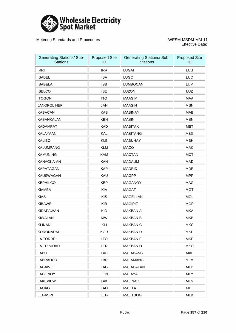
Metering Standards and Procedures WESM-MSDM-MM-11 Effective Date:
Public Page 157 of 210
Generating Stations/ Sub-Stations
Proposed Site ID
Generating Stations/ Sub-Stations
Proposed Site ID
IRRI IRR LUGAIT LUG
ISABEL ISA LUGO LUO
ISABELA ISB LUMBOCAN LUM
ISELCO ISE LUZON LUZ
ITOGON ITO MAASIM MAA
JANOPOL HEP JAN MAASIN MSN
KABACAN KAB MABINAY MAB
KABANKALAN KBN MABINI MBN
KADAMPAT KAD MABITAK MBT
KALAYAAN KAL MABITANG MBG
KALIBO KLB MABUHAY MBH
KALUMPANG KLM MACO MAC
KAMUNING KAM MACTAN MCT
KANAGKA-AN KAN MADAUM MAD
KAPATAGAN KAP MADRID MDR
KAUSWAGAN KAU MAGPP MPP
KEPHILCO KEP MAGANOY MAG
KIAMBA KIA MAGAT MGT
KIAS KIS MAGELLAN MGL
KIBAWE KIB MAGIPIT MGP
KIDAPAWAN KID MAKBAN A MKA
KIWALAN KIW MAKBAN B MKB
KLINAN KLI MAKBAN C MKC
KORONADAL KOR MAKBAN D MKD
LA TORRE LTO MAKBAN E MKE
LA TRINIDAD LTR MAKBAN O MKO
LABO LAB MALABANG MAL
LABRADOR LBR MALAMANG MLM
LAGAWE LAG MALAPATAN MLP
LAGONOY LGN MALAYA MLY
LAKEVIEW LAK MALINAO MLN
LAOAG LAO MALITA MLT
LEGASPI LEG MALITBOG MLB

Metering Standards and Procedures WESM-MSDM-MM-11 Effective Date:
Public Page 158 of 210
Generating Stations/ Sub-Stations
Proposed Site ID
Generating Stations/ Sub-Stations
Proposed Site ID
LEMON LEM MALOLOS MLL
LEPANTOMINES LEP MANDAUE MAN
LIBMANAN LIB MANGALDAN MNG
LIGAO LIG MANSILANGAN MNS
LIMALAND LIM MAPALAD MAP
LIMAY LMY MAPASO MPS
LINGAYEN LIN MARAMAG MAR
LIPA LIP MARAWI MRW
LOBOC LOB MARIBOJOC MRB
LOS BANOS LBA MARICALUM MRC
MARIVELES MRV NULING NUL
MASINLOC MAS NUVELCO NUV
MASIWAY MSW OBRERO OBR
MATANO MAT OKOY OKO
MATI MAI OLDBANTAY OLD
MAWAB MAW OLONGAPO OLO
MCARTHUR MCA ONGON ONG
MCCI MCC OPOL OPO
MCI MCI ORIONTAP ORI
MECO MEC ORMAT ORM
MEDELLIN MED ORMOC ORC
MEPZ MEP OROQUIETA ORO
MEXICO MEX OVERTON OVE
MIC MIC OZAMIS OZA
MIDSAYAP MID PACEMCO PAC
MILAGRO MIL PAF PAF
MIRANT MIR PAGADIAN PAG
MOBILE MOB PAGBILAO PGB
MOLAVE MOL PAGUDPOD PGD
MOPRECO MOP PALAPALA PAL
MORONG MOR PALINPINON PLN
MPCC MPC PALO PAO
MRO MRO PAMPLONA PAM

Metering Standards and Procedures WESM-MSDM-MM-11 Effective Date:
Public Page 159 of 210
Generating Stations/ Sub-Stations
Proposed Site ID
Generating Stations/ Sub-Stations
Proposed Site ID
MRSQ MRS PANAS PAN
MT VIEW MVI PANAY DIESEL PNY
MULANAY MUL PANELCO PNL
MUNOZ MUN PANIQUI PNQ
NABAS NAB PANITAN PNT
NABUNTURAN NBN PANTABANGAN PNB
NAGA LUZON NLU PARACALE PAR
NAGUILIAN NAG PASAR PAS
NAPOT NAP PATAG PAT
NARVACAN NAR PAYOCPOC PAY
NASIPIT NAS PELCO PEL
NASUGBU NSG PETRON PET
NASUJI NSJ PEZA PEZ
NDMC NDM PFC PFC
NEGROS GPP NEG PFM PFM
NENENG NEN PGI PGI
NEWBANTAY NEW PHILPHOS PHL
NEWLOON NWL PHILSECO PHS
NEWTECH NWT PHIVIDEC PHV
NIA NIA PICOP PIC
NMPC NMP PPC PPC
NOVALICHES NOV SANTIAGO SNT
NSC NSC SARA SAR
PILOT PIL SARI SAI
PINAMUCAN PIN SBMA SBM
PITOGO PIT SEMI SEM
PMA PMA SFELAPCO SFL
PMSC PMS SIBALOM SIB
PNOC PNO SIBONGA SBN
PNOC-EDC CEBU C1 PC1 SIGPIT SIG
PNOC-EDC CEBU C2 PC2 SIGUEL SGL
PNOC-EDC LUZON C1 PL1 SILAY SIL
PNOC-EDC LUZON C2 PL2 SIMUAY SIM
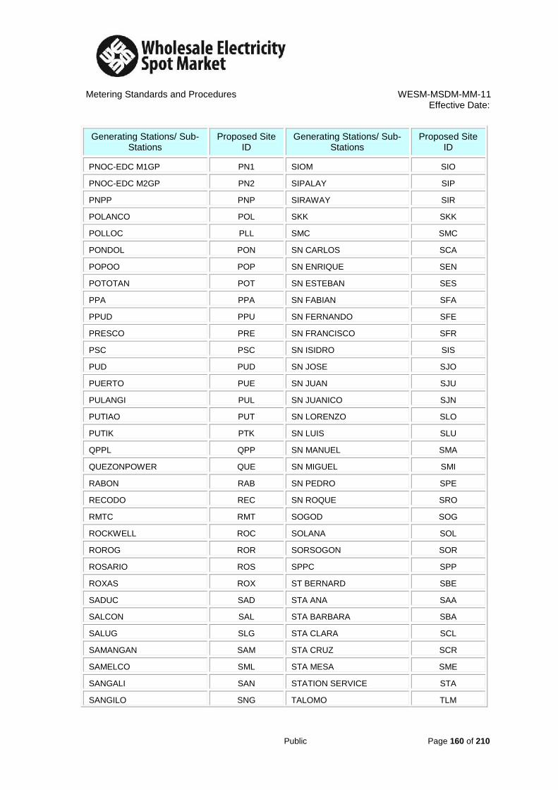
Metering Standards and Procedures WESM-MSDM-MM-11 Effective Date:
Public Page 160 of 210
Generating Stations/ Sub-Stations
Proposed Site ID
Generating Stations/ Sub-Stations
Proposed Site ID
PNOC-EDC M1GP PN1 SIOM SIO
PNOC-EDC M2GP PN2 SIPALAY SIP
PNPP PNP SIRAWAY SIR
POLANCO POL SKK SKK
POLLOC PLL SMC SMC
PONDOL PON SN CARLOS SCA
POPOO POP SN ENRIQUE SEN
POTOTAN POT SN ESTEBAN SES
PPA PPA SN FABIAN SFA
PPUD PPU SN FERNANDO SFE
PRESCO PRE SN FRANCISCO SFR
PSC PSC SN ISIDRO SIS
PUD PUD SN JOSE SJO
PUERTO PUE SN JUAN SJU
PULANGI PUL SN JUANICO SJN
PUTIAO PUT SN LORENZO SLO
PUTIK PTK SN LUIS SLU
QPPL QPP SN MANUEL SMA
QUEZONPOWER QUE SN MIGUEL SMI
RABON RAB SN PEDRO SPE
RECODO REC SN ROQUE SRO
RMTC RMT SOGOD SOG
ROCKWELL ROC SOLANA SOL
ROROG ROR SORSOGON SOR
ROSARIO ROS SPPC SPP
ROXAS ROX ST BERNARD SBE
SADUC SAD STA ANA SAA
SALCON SAL STA BARBARA SBA
SALUG SLG STA CLARA SCL
SAMANGAN SAM STA CRUZ SCR
SAMELCO SML STA MESA SME
SANGALI SAN STATION SERVICE STA
SANGILO SNG TALOMO TLM

Metering Standards and Procedures WESM-MSDM-MM-11 Effective Date:
Public Page 161 of 210
Generating Stations/ Sub-Stations
Proposed Site ID
Generating Stations/ Sub-Stations
Proposed Site ID
SCFTPP SCF TIGBAUAN TIG
STA RITA SRI TINAMBAC TIN
STA ROSA SRS TINDALO TND
STEELCORP STE TIPCO TIP
SUAL SUA TIWI A TWA
SUBA SUB TIWI B TWB
SUBIC SBC TIWI C TWC
SUCAT SUC TOLOSA TOL
SUKELCO SUK TOMONTON TOM
SUNVALLEY SUN TONGONAN TON
SURALLAH SUR TPC TPC
SURICON SRC TPS TPS
SURIGAO SRG TRANSASIA TRA
TAAL TAA TRENTO TRE
TABANGO TAB TRINIDAD TRI
TABUK TBK TUBIGON TUB
TACLOBAN TAC TUGAS TUG
TACURONG TCR TUGUEGARAO TGG
TAFT TAF TUNGA TUN
TAGAYTAY TAG TUNGAWAN TNG
TAGBILARAN TGB UBAY UBA
TAGKAWAYAN TGK UCC UCC
TAGOLOAN TGL UMIRAY UMI
TAGUM TGM UPPC UPP
TALAKAG TAL URDANETA URD
TALAVERA TLV VALLADOLID VAL
TALISAY TLS VECO VEC
TANAUAN TAN VMC VMC
TAPG TAP VOA VOA
TARELCO TAR WMPC WMP
TAYABAS TAY ZAMBALESBASE ZAM
TAYUG TYG ZAMBOANGA ZMB
TEI TEI ZAPOTE ZAP

Metering Standards and Procedures WESM-MSDM-MM-11 Effective Date:
Public Page 162 of 210
Generating Stations/ Sub-Stations
Proposed Site ID
Generating Stations/ Sub-Stations
Proposed Site ID
TERNATE TER
TABLE 10 – METERED PARTICIPANT ID
Metered Participant Proposed ID Metered Participant Proposed ID
ABRECO ABRE BACNOTAN STEEL BCNT
ACC ACCZ BALOI BALO
ADC ADCZ BARIT BARI
AEC AECZ BATAAN REFINING BATA
AFP AFPZ BATELEC I BAT1
AGP AGPZ BATELEC II BAT2
AGGREKO AGGR BBTI BBTI
AGUS AGUS BCC BCCZ
AGUSAN AGSN BCI BCIZ
AHEP AHEP BCM BCMZ
AKELCO AKEL BCWD BCWD
ALECO ALEC BEI BEIZ
ALTURAS ALTU BENECO BENE
AMLAN AMLA BEPZ BEPZ
ANECO ANEC BHEP BHEP
ANGAT ANGA BHEPP BHPP
ANTECO ANTE BHPI BHPI
APEX APEX BILECO BILE
API APIZ BLCI BLCI
ASELCO ASEL BOHECO I BOH1
AURELCO AURE BOHECO II BOH2
BAB (PAF) BABP BOHOL DIESEL BOHO
BACMAN BACM CPC CPCZ
BPPMI BPPM BPPC BPPC
BSP BSPZ CPPC CPPC
BTPI BTPI DANECO DANE
BUSCO BUSC DASURECO DASU
BUSECO BUSE DECORP DECO

Metering Standards and Procedures WESM-MSDM-MM-11 Effective Date:
Public Page 163 of 210
Metered Participant Proposed ID Metered Participant Proposed ID
CABCOM CABC DISTILLERIA DE BAGO DIST
CAGELCO I CAG1 DLPC DLPC
CAGELCO II CAG2 DMPI DMPI
CALACA CALA DND DNDZ
CAMELCO CAME DOLEPHIL DOLE
CANLUBANG SUGAR CANL DORECO DORE
CANORECO CANO DORELCO DRLC
CAPELCO CAPE DOW DOWZ
CASECNAN CASE DUCC DUCC
CASURECO I CAS1 DUCOMI DUCO
CASURECO II CAS2 DURACOM DURA
CASURECO II CAS3 E.B. MENDOZA EBME
CASURECO IV CAS4 EAUC EAUC
CAT CATZ ECOSIP ECOS
CEBECO I CEB1 EDISON COGEN EDIS
CEBECO II CEB2 EEI EEIZ
CEDC CEDC ELEGANT STEEL ELEG
CELCOR CELC ENRON ENRO
CENECO CENE ERDB-FORI ERDB
CENPELCO CENP ESAMELCO ESAM
CENTRAL ENG’G CENT FAB FABZ
CEPALCO CEPA FCC FCCZ
CEPZA CEPZ FCVC FCVC
CEZA CEZA FGPC FGPC
CHEPP CHEP FIBECO FIBE
CORDERO CORD FLECO FLEC
CLSU CLSU FPIC FPIC
COC COCZ FPRDI FPRD
COCOCHEM COCO GENSAN HSG GENS
COLIGHT COLI GIPCS GIPC
COTELCO COTE GMC GMCZ
COTO MINES COTO GPM GPMZ
GUIMELCO GUIM LIMAO LMZY
HCC HCCZ LIPA ICE PLANT LIPA

Metering Standards and Procedures WESM-MSDM-MM-11 Effective Date:
Public Page 164 of 210
Metered Participant Proposed ID Metered Participant Proposed ID
HEDCOR HEDC LMG CHEMICALS LMGC
HOPEWELL HOPE LOBOC LOBO
ICC ICCZ LUECO LUEC
IEEC IEEC LUELCO LUEL
IFELCO IFEL LUZON HYDRO LUZO
ILECO I ILE1 MAGAT MAGA
ILECO II ILE2 MAGELCO MAGE
ILECO III ILE3 MAGPP MAGP
ILIJAN ILIJ MAKBAN A MAKA
ILPI ILPI MAKBAN B MAKB
INDOPHIL INDO MAKBAN C MAKC
INEC INEC MANSONS MANS
INGASCO INGA MARCELA MARC
INNOVE INNO MASINLOC MASI
IRRI IRRI MASIWAY MSWY
ISECO ISEC MCCI MCCI
ISELCO I ISE1 MCI MCIZ
ISELCO II ISE2 MECO MECO
ITC ITCZ MECO MZYX
ITOGON MINES ITOG MEGAPACK MEGA
JANOPOL JANO MENDECO MEND
KAELCO KAEL MENZI-AGRI CORP MENZ
KALAYAAN KALA MEPZA MEPZ
KIBAWE HSG KIBA MGN MGNZ
KIELCO KIEL MIC MICZ
KPSPP KPSP MIRANT MIRA
KSP KSPZ MMC MMCZ
LANECO LANE MOELCI I MOE1
LASURECO LASU MOELCI II MOE2
LEPANTO MINES LEPA MOPRECO MOPR
LEYECO II LEY2 MORESCO I MOR1
LEYECO III LEY3 MORESCO II MOR2
LEYECO IV LEY4 MSMC MSMC
LEYECO V LEY5 MSU MSUZ

Metering Standards and Procedures WESM-MSDM-MM-11 Effective Date:
Public Page 165 of 210
Metered Participant Proposed ID Metered Participant Proposed ID
LEYTE GPP LEYT MUNICIPAL OF BAUAN MUNI
LIMALAND LIMA MVC MVCZ
MWSI MWSI PCC PCCZ
MWSS MWSS PELCO I PEL1
NALCO NALC PELCO II PEL2
NCC NCCZ PELCO III PEL3
NEECO I NEE1 PENELCO PENE
NEECO II NEE2 PFM PFMZ
NEGROS GPP NEGR PGI PGIZ
NEWTECH INDUSTRIES NEWT PHILPOS PHLP
NIA-AMPUCAO NIAA PHILTOWN PHLT
NIA-AMRIS NMLN PHIVIDEC PHIV
NIA-AMULUNG NMLG PICOP PICO
NIA-BALIGATAN NIAB PICOP NEWTECH PCPN
NIA-BUTUAN NBTN PILIPINAS SHELL PILI
NIA-CAUAYAN NIAC PILMICO PILM
NIA-PANTABANGAN NIAP PLANTERS PLAN
NIA-SOLANA NIAS PMA PMAZ
NMPC NMPC PMC PMCZ
NMT NMTZ PMSC-BOHOL PMSC
NOBEL NOBE PMSC-CEBU PMSB
NOCECO NOCE PNOC-CAMARINES SUR PNOC
NORECO I NOR1 PNOC-IPP PNCP
NORECO II NOR2 PNOC-LAGUNA PNCL
NORSAMELCO NORS PNOC-LEYTE PNCY
NPC NPCZ PNOC-NEGROS PNCN
NPC HSG NPCH PNOC-SWMI PNCS
NSC NSCZ PNPP PNPP
NUVELCO NUVE PPC PPCZ
ORICA ORIC PRESCO PRES
ORMAT ORMA PSC PSCZ
PACEMCO PACE PSIC PSIC
PAF PAFZ PSWR PSWR
PANAY DIESEL PANA PUD-OLONGAPO PUDO
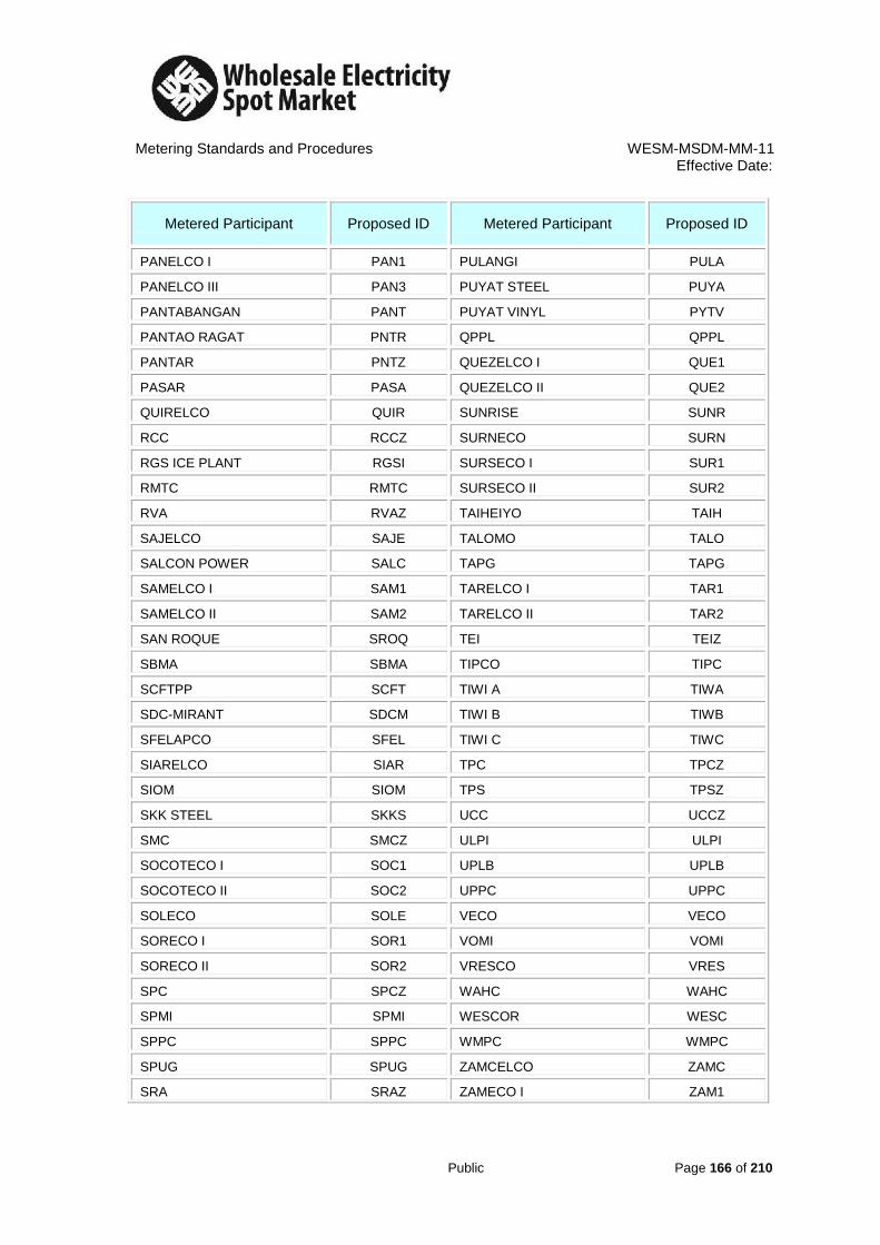
Metering Standards and Procedures WESM-MSDM-MM-11 Effective Date:
Public Page 166 of 210
Metered Participant Proposed ID Metered Participant Proposed ID
PANELCO I PAN1 PULANGI PULA
PANELCO III PAN3 PUYAT STEEL PUYA
PANTABANGAN PANT PUYAT VINYL PYTV
PANTAO RAGAT PNTR QPPL QPPL
PANTAR PNTZ QUEZELCO I QUE1
PASAR PASA QUEZELCO II QUE2
QUIRELCO QUIR SUNRISE SUNR
RCC RCCZ SURNECO SURN
RGS ICE PLANT RGSI SURSECO I SUR1
RMTC RMTC SURSECO II SUR2
RVA RVAZ TAIHEIYO TAIH
SAJELCO SAJE TALOMO TALO
SALCON POWER SALC TAPG TAPG
SAMELCO I SAM1 TARELCO I TAR1
SAMELCO II SAM2 TARELCO II TAR2
SAN ROQUE SROQ TEI TEIZ
SBMA SBMA TIPCO TIPC
SCFTPP SCFT TIWI A TIWA
SDC-MIRANT SDCM TIWI B TIWB
SFELAPCO SFEL TIWI C TIWC
SIARELCO SIAR TPC TPCZ
SIOM SIOM TPS TPSZ
SKK STEEL SKKS UCC UCCZ
SMC SMCZ ULPI ULPI
SOCOTECO I SOC1 UPLB UPLB
SOCOTECO II SOC2 UPPC UPPC
SOLECO SOLE VECO VECO
SORECO I SOR1 VOMI VOMI
SORECO II SOR2 VRESCO VRES
SPC SPCZ WAHC WAHC
SPMI SPMI WESCOR WESC
SPPC SPPC WMPC WMPC
SPUG SPUG ZAMCELCO ZAMC
SRA SRAZ ZAMECO I ZAM1

Metering Standards and Procedures WESM-MSDM-MM-11 Effective Date:
Public Page 167 of 210
Metered Participant Proposed ID Metered Participant Proposed ID
STATION SERVICE STAT ZAMECO II ZAM2
STEEL CORP STEE ZAMSURECO I ZMS1
STEPHAN STEP ZAMSURECO II ZMS2
SUBIC SHIPYARD SUBI ZANECO ZANE
SUKELCO SUKE
Table 11 – Metering Equipment, Devices and Auxiliaries
Designation Description
CT Current Transformer
LA Lightning Arrester
MB Meter Box
MD Modem
MF Multi-function Electronic Meter (Smart Meter)
PT Potential Transformer
ST Metering Structure
TS Meter Test Switch

Metering Standards and Procedures WESM-MSDM-MM-11 Effective Date:
Public Page 168 of 210
PROCEDURES OF SITE EQUIPMENT AND IDENTIFICATION
Procedure No. 1
1. The Site ID for all generating stations and substations connected to the grid shall be identified by its first three letters of the station’s name;
Note: The Site ID for generating stations or substations whose name is consisting of
only three letters, the Site ID will be its name itself.
Stations Site ID
ABAGA ABA
BABATNGON BAB
BCI BCI
CADIZ CAD
CIP CIP
EDISON EDI
FATIMA FAT
2. Any generating stations or substations that will appear to have identical Site IDs, the first
three letters of the stations name (item 1) shall be replaced by the first three/ next consonant letters of the station’s name. Note: - If the first letter of the station’s name is not a consonant, the first letter (a vowel) shall be carried followed by the succeeding two/ next consonant letters of the station’s name.
- Among the identical Site IDs, the one to come first will have the first three letters/ consonant of the stations name and the rest will apply the procedure on item 2.
- Adding of “Z”, “Y” or “X” to the first two consonants of the stations name is applied when all possible site IDs were used and duplication still exists.
Stations ITEM 1 (Identical Site ID)
ITEM 2 (Identical Site ID)
Site ID
AMBAGO AMB AMB AMB
AMBUKLAO AMB AMK AMK
BAIS BAI BAI
BALANGA BAL BAL BAL
BALAOAN BAL BLN BLN BLN
BALASAN BAL BLS BLS
BALATOC BAL BLT BLT
BALDOZA BAL BLD BLD

Metering Standards and Procedures WESM-MSDM-MM-11 Effective Date:
Public Page 169 of 210
Stations ITEM 1 (Identical Site ID)
ITEM 2 (Identical Site ID)
Site ID
BALER BAL BLR BLR
BALIBAGO BAL BLB BLB
BALIGATANHEP BAL BLG BLG BLG
BALINGOAN BAL BLN BLG BLN BNG BNG
BALINTAWAK BAL BLN BLT BLW BLK BLK
BALIWAG BAL BLW BLW BLW
BALIWASAN BAL BLW BLS BLN BWS BWS
BALOC BAL BLC BLC
BALOIAIRPORT BAL BLR BLP BLP
BANGUED BAN BAN BAN
BANI BAN BNZ BNZ
CABACUNGAN CAB CAB CAB
CABADBARAN CAB CBD CBD
CABAGAN CAB CBG CBG CBG
CABANATUAN CAB CBN CBN
CABARROGUIS CAB CBR CBR
CAT CAT CAT CAT
CATARMAN CAT CTR CTR
CATBALOGAN CAT CTB CTB
CATEEL CAT CTL CTL
CATIGBI-AN CAT CTG CTG CTG
CATUBIG CAT CTB CTG CBG CTZ CTZ
3. For generating stations like Makban and Tiwi Complex, the Site IDs shall be the first two
consonants of the stations name and the letter A, B, C, D, E… Note: - For Metered Participants like Makban and Tiwi Complex that will appear to have identical Site IDs, replace the 2
nd consonants with its next consonant and add the letter A,
B, C, D, E...
Stations Site ID
MAKBAN PLANT A MKA
MAKBAN PLANT B MKB
MAKBAN PLANT ORMAT MKO
TIWI PLANT A TWA
TIWI PLANT B TWB
4. For generating stations and substations whose station name begins with La, Mt, San or
Sta, the Site IDs shall be the first letter of the words La, Mt, San or Sta and the first two letters after the words La, Mt, San or Sta.
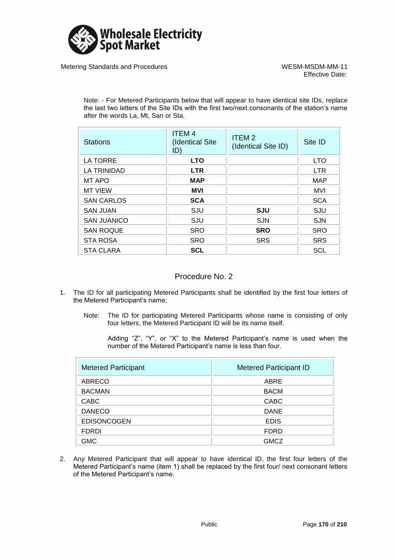
Metering Standards and Procedures WESM-MSDM-MM-11 Effective Date:
Public Page 170 of 210
Note: - For Metered Participants below that will appear to have identical site IDs, replace the last two letters of the Site IDs with the first two/next consonants of the station’s name after the words La, Mt, San or Sta.
Stations ITEM 4 (Identical Site ID)
ITEM 2 (Identical Site ID)
Site ID
LA TORRE LTO LTO
LA TRINIDAD LTR LTR
MT APO MAP MAP
MT VIEW MVI MVI
SAN CARLOS SCA SCA
SAN JUAN SJU SJU SJU
SAN JUANICO SJU SJN SJN
SAN ROQUE SRO SRO SRO
STA ROSA SRO SRS SRS
STA CLARA SCL SCL
Procedure No. 2 1. The ID for all participating Metered Participants shall be identified by the first four letters of
the Metered Participant’s name;
Note: The ID for participating Metered Participants whose name is consisting of only four letters, the Metered Participant ID will be its name itself.
Adding “Z”, “Y”, or “X” to the Metered Participant’s name is used when the
number of the Metered Participant’s name is less than four.
Metered Participant Metered Participant ID
ABRECO ABRE
BACMAN BACM
CABC CABC
DANECO DANE
EDISONCOGEN EDIS
FDRDI FDRD
GMC GMCZ
2. Any Metered Participant that will appear to have identical ID, the first four letters of the
Metered Participant’s name (item 1) shall be replaced by the first four/ next consonant letters of the Metered Participant’s name.

Metering Standards and Procedures WESM-MSDM-MM-11 Effective Date:
Public Page 171 of 210
Note: - If the first letter of the Metered Participant’s name is not a consonant, the first letter (a vowel) shall be carried followed by the succeeding three/ next consonant letters of the Metered Participant’s name.
- AMOng the identical Metered Participant IDs, the one to come first will have the
first four letters/ consonant of the Metered Participant’s name and the rest will apply the procedure on item 2.
- Adding of “Z”, “Y” or “X” to the first three/remaining consonants of the Metered Participant’s name is applied when all possible IDs were used and duplication still exists.
Metered Participant ITEM 1 (ID)
ITEM 2 (ID)
(Identical ID)
Metered Participant ID
BACNOTANCEMENT BACN BACN BACN
BACNOTANSTEEL BACN BCNT BCNT
DORECO DORE DORE DORE
DORELCO DORE DRLC DRLC
LIMALAD LIMA LIMA LIMA
LIMAO LIMA LMZY LMZY
PANTABANGAN PANT PANT PANT
PANTAORAGAT PANT PNTR PNTR PNTR
PANTAR PANT PNTR PNTZ PNTZ
3. For Metered Participants like Makban and Tiwi Complex, the IDs shall be the first three
letters of the Metered Participant’s name and the letter A, B, C, D, E… Note: - For Metered Participants like Makban and Tiwi Complex that will appear to have identical IDs, replace the first three letters of the Metered Participant’s name with its first three/remaining consonants or apply item 2.
Metered Participant Metered Participant ID
MAKBAN PLANT A MAKA
MAKBAN PLANT B MAKB
TIWI PLANT A TIWA
TIWI PLANT B TIWB
4. For Metered Participants whose names begin with La, Mt, San or Sta, the IDs shall be the
first letter of the words La, Mt, San or Sta and the first three letters after the words La, Mt, San or Sta.
Note: - For Metered Participants below that will appear to have identical IDs, replace the last three letters of the Metered Participant’s ID with its first three/remaining consonant after the words La, Mt, San or Sta or just simply apply item 2.
Metered Participant Metered Participant ID

Metering Standards and Procedures WESM-MSDM-MM-11 Effective Date:
Public Page 172 of 210
SAN JOSE SJOS
SAN ROQUE SROQ
5. For Metered Participants like Pelco and Zameco Complex, the IDs shall be the first three
letters of the customer’s name and the equivalent decimal of the given Roman Numerals.
Note: - For Metered Participants below that will appear to have identical IDs, replace the first three letters of the Metered Participant’s name with its first three consonants (Item 2) plus the equivalent decimal of the given Roman Numerals.
Metered Participant ITEM 1 (ID)
ITEM 2 (ID)
Metered Participant ID
PELCO I PEL1 PEL1
PELCO II PEL2 PEL2
PELCO III PEL3 PEL3
ZAMECO I ZAM1 ZAM1 ZAM1
ZAMELCO II ZAM2 ZAM2 ZAM2
ZAMSURECO I ZAM1 ZMS1 ZMS1
ZAMSURECO II ZAM2 ZMS2 ZMS2

Metering Standards and Procedures WESM-MSDM-MM-11 Effective Date:
Public Page 173 of 210
SITE – SPECIFIC LOSS ADJUSTMENT Customer Case 1: Single Settlement Point
A metering point is connected to only one MTN:
a. Case 1 – A: only one metering point is presently connected to the MTN (figure 1)
Figure 1 kWMi = (kWhMi-15min + kWhMi-30min + kWhMi-45min + kWhMi-00min) ÷ 1h kVarMi = (kVarhMi-15min + kVarhMi-30min + kVarhMi-45min + kVarhMi-00min) ÷ 1h ILine = kWMi ÷ ((√3) * V * pfMi) pfMi = cos (tan
-1 (kVarMi ÷ kWMi))
LinekW-Loss = (ILine)
2 * RLine
RLine = ra * L LinekVar-Loss = (ILine)
2 * XLine
XLine = Xl * L CoreLoss-Mi = TCoreLoss * (kWMi ÷ ) = T1CoreLoss ÷ 1 CopperLoss-Mi = ((kWMi ÷ pfMi) ÷ TkVA-Rating)
2 * PShort-Circuit
TotalkW-Loss = LinekW-Loss + CoreLoss-Mi + CopperLoss-Mi
SSLF = 1 + (TotalkW-Loss + kWMi) AdjustedkW = TotalkWLoss + kWMi = SSLF * kWMi
L
Market Trading Node
Transformer Loss
Line Loss
Mi
ILine
n
∑
kWMi
i =1

Metering Standards and Procedures WESM-MSDM-MM-11 Effective Date:
Public Page 174 of 210
b. Case 1 – B: numerous metering points connected to, or are sharing the same MTN (figure 2)
Figure 2
Active and Reactive Power: kWM1 = (kWhM1-15min + kWhM1-30min + kWhM1-45min + kWhM1-00min) ÷ 1h kVarM1 = (kVarhM1-15min + kVarhM1-30min + kVarhM1-45min + kVarhM1-00min) ÷ 1h kWM2 = (kWhM2-15min + kWhM2-30min + kWhM2-45min + kWhM2-00min) ÷ 1h kVarM2 = (kVarhM2-15min + kVarhM2-30min + kVarhM2-45min + kVarhM2-00min) ÷ 1h kWM3 = (kWhM3-15min + kWhM3-30min + kWhM3-45min + kWhM3-00min) ÷ 1h kVarM3 = (kVarhM3-15min + kVarhM3-30min + kVarhM3-45min + kVarhM3-00min) ÷ 1h kWM4 = (kWhM4-15min + kWhM4-30min + kWhM4-45min + kWhM4-00min) ÷ 1h kVarM4 = (kVarhM4-15min + kVarhM4-30min + kVarhM4-45min + kVarhM4-00min) ÷ 1h Line Currents and Line Losses: I1 = kWM1 ÷ ((√3) * V1 * pf1) = kWM1 ÷ ((√3) * V1 * cos (tan
-1 (kVarM1 ÷ kWM1)))
I3 = kWM2 ÷ ((√3) * V2 * pf2) = kWM2 ÷ ((√3) * V2 * cos (tan
-1 (kVarM2 ÷ kWM2)))
L3
Node 2
M
4
M
2
M
3
L2
L4
L6 L5
I2 I3
I4
I5
I6
Node 1
Node 3
Market Trading Node
Transformer 2 loss
L1
I1
M
1
Transformer 1 loss

Metering Standards and Procedures WESM-MSDM-MM-11 Effective Date:
Public Page 175 of 210
I5 = kWM3 ÷ ((√3) * V3 * pf3) = kWM3 ÷ ((√3) * V3 * cos (tan
-1 (kVarM3 ÷ kWM3)))
I6 = kWM4 ÷ ((√3) * V4 * pf4) = kWM4 ÷ ((√3) * V4 * cos (tan
-1 (kVarM4 ÷ kWM4)))
Line5-kW-Loss = (I5)
2 * R5 = (I5)
2 * (ra-5 * L5)
Line5-kVar-Loss = (I5)
2 * X5 = (I5)
2 * (Xl-5 * L5)
Line6-kW-Loss = (I6)
2 * R6 = (I6)
2 * (ra-6 * L6)
Line6-kVar-Loss = (I6)
2 * X6 = (I6)
2 * (Xl-6 * L6)
Total Active Power at Node 3 (kWN-3) = kWM3 + kWM4 + Line5-kW-Loss + Line6-kW-Loss
Total Reactive Power at Node 3 (kVarN-3) = kVarM3 + kVarM4 + Line5-kVar-Loss + Line6-kVar-Loss
I4 = kWN-3 ÷ ((√3) * VN-3 * pfN-3) = kWN-3 ÷ ((√3) * VN-3 * cos (tan
-1 (kVarN-3 ÷ kWN-3)))
Line4-kW-Loss = (I4)
2 * R4 = (I4)
2 * (ra-4 * L4)
Line4-kVar-Loss = (I4)
2 * X4 = (I4)
2 * (Xl-4 * L4)
Line3-kW-Loss = (I3)
2 * R3 = (I3)
2 * (ra-3 * L3)
Line3-kVar-Loss = (I3)
2 * X3 = (I3)
2 * (Xl-3 * L3)
Total Active Power at Node 2 (kWN-2) = kWM2 + kWM3 + kWM4 + Line3-kW-Loss + Line4-kW-Loss + Line5-kW-Loss + Line6-kW-Loss
Total Reactive Power at Node 2 (kVarN-2) = kVarM2 + kVarM3 + kVarM4 + Line3-kVar-Loss + Line4-kVar-Loss + Line5-kVar-Loss + Line6-kVar-Loss
I2 = kWN-2 ÷ ((√3) * VN-2 * pfN-2) = kWN-2 ÷ ((√3) * VN-2 * cos (tan
-1 (kVarN-2 ÷ kWN-2)))
Line2-kW-Loss = (I2)
2 * R2 = (I2)
2 * (ra-2 * L2)
Line2-kVar-Loss = (I2)
2 * X2 = (I2)
2 * (Xl-2 * L2)
Line1-kW-Loss = (I1)
2 * R1 = (I1)
2 * (ra-1 * L1)
Line1-kVar-Loss = (I1)
2 * X1 = (I1)
2 * (Xl-1 * L1)
Distributing Line4-kW-Loss For M3, Line4-kW-Loss-M3 = (Line4-kW-Loss * (kWM3 + Line5-kW-Loss)) ÷ kWN-3 For M4, Line4-kW-Loss-M4 = (Line4-kW-Loss * (kWM4 + Line6-kW-Loss)) ÷ kWN-3 Distributing Line2-kW-Loss For M2, Line2-kW-Loss-M2 = (Line2-kW-Loss * (kWM2 + Line3-kW-Loss)) ÷ kWN-2 For M3, Line2-kW-Loss-M3 = (Line2-kW-Loss * (kWM3 + Line5-kW-Loss + Line4-kW-Loss-M3)) ÷ kWN-2

Metering Standards and Procedures WESM-MSDM-MM-11 Effective Date:
Public Page 176 of 210
For M4, Line2-kW-Loss-M4 = (Line2-kW-Loss * (kWM4 + Line6-kW-Loss + Line4-kW-Loss-M4)) ÷ kWN-2 Transformer Losses: T1CoreLoss-M1 = T1CoreLoss * (kWM1 ÷ ) = T1CoreLoss ÷ 1 T1CopperLoss-M1 = ((kWM1 ÷ pf1) ÷ T1kVA-Rating)
2 * PShort-Circuit-T1
T2CoreLoss-M1 = T2CoreLoss * (kWM1 ÷ ) T2CoreLoss-M2 = T2CoreLoss * (kWM2 ÷ ) T2CoreLoss-M3 = T2CoreLoss * (kWM3 ÷ ) T2CoreLoss-M4 = T2CoreLoss * (kWM4 ÷ ) T2CopperLoss = ((kWN-1 ÷ pfN-1) ÷ T2kVA-Rating)
2 * PShort-Circuit-T2
T2CopperLoss-M1 = T2CopperLoss * (kWM1 + Line1-kW-Loss) ÷ kWN-1 T2CopperLoss-M2 = T2CopperLoss * (kWM2 + Line3-kW-Loss + Line2-kW-Loss-M2) ÷ kWN-1 T2CopperLoss-M3 = T2CopperLoss * (kWM3 + Line5-kW-Loss + Line4-kW-Loss-M3 + Line2-kW-Loss-M3) ÷
kWN-1 T2CopperLoss-M4 = T2CopperLoss * (kWM4 + Line6-kW-Loss + Line4-kW-Loss-M4 + Line2-kW-Loss-M4) ÷
kWN-1 Total Active Loss for each Meter: TotalkW-Loss-M1 = Line1-kW-Loss + T1CoreLoss + T1CopperLoss-M1 + T2CoreLoss-M1 +
T2CopperLoss-M1 TotalkW-Loss-M2 = Line3-kW-Loss + Line2-kW-Loss-M2 + T2CoreLoss-M2 + T2CopperLoss-M2 TotalkW-Loss-M3 = Line5-kW-Loss + Line4-kW-Loss-M3 + Line2-kW-Loss-M3 + T2CoreLoss-M3 +
T2CopperLoss-M3 TotalkW-Loss-M4 = Line6-kW-Loss + Line4-kW-Loss-M4 + Line2-kW-Loss-M4 + T2CoreLoss-M4 +
T2CopperLoss-M4 SSLF: SSLFM1 = 1 + (TotalkW-Loss-M1 ÷ kWM1) SSLFM2 = 1 + (TotalkW-Loss-M2 ÷ kWM2) SSLFM3 = 1 + (TotalkW-Loss-M3 ÷ kWM3) SSLFM4 = 1 + (TotalkW-Loss-M4 ÷ kWM4)
n
∑
kWMi
i =1
n
∑
kWMi
i =1
n
∑
kWMi
i =1
n
∑
kWMi
i =1
n
∑
kWMi
i =1

Metering Standards and Procedures WESM-MSDM-MM-11 Effective Date:
Public Page 177 of 210
Adjusted Active Power: AdjustedkW-M1 = TotalkW-Loss-M1 + kWM1 AdjustedkW-M2 = TotalkW-Loss-M2 + kWM2 AdjustedkW-M3 = TotalkW-Loss-M3 + kWM3 AdjustedkW-M4 = TotalkW-Loss-M4 + kWM4
In the event that Meter 4 reading becomes zero (0), see figure 3:
Figure 3
Active and Reactive Power: kWM1 = (kWhM1-15min + kWhM1-30min + kWhM1-45min + kWhM1-00min) ÷ 1h kVarM1 = (kVarhM1-15min + kVarhM1-30min + kVarhM1-45min + kVarhM1-00min) ÷ 1h kWM2 = (kWhM2-15min + kWhM2-30min + kWhM2-45min + kWhM2-00min) ÷ 1h kVarM2 = (kVarhM2-15min + kVarhM2-30min + kVarhM2-45min + kVarhM2-00min) ÷ 1h kWM3 = (kWhM3-15min + kWhM3-30min + kWhM3-45min + kWhM3-00min) ÷ 1h
L5
I2 I3
I4
I4
L3
Node 2
M
4
M
2
M
3
L2
L4
L6
Node 1
Node 3
Market Trading Node
Transformer 2 loss
L1
I1
M
1
Transformer 1 loss

Metering Standards and Procedures WESM-MSDM-MM-11 Effective Date:
Public Page 178 of 210
kVarM3 = (kVarhM3-15min + kVarhM3-30min + kVarhM3-45min + kVarhM3-00min) ÷ 1h Line Currents and Line Losses: I1 = kWM1 ÷ ((√3) * V1 * pf1) = kWM1 ÷ ((√3) * V1 * cos (tan
-1 (kVarM1 ÷ kWM1)))
I3 = kWM2 ÷ ((√3) * V2 * pf2) = kWM2 ÷ ((√3) * V2 * cos (tan
-1 (kVarM2 ÷ kWM2)))
I4 = kWM3 ÷ ((√3) * V3 * pf3) = kWM3 ÷ ((√3) * V3 * cos (tan
-1 (kVarM3 ÷ kWM3)))
Line5-kW-Loss = (I4)
2 * R5 = (I4)
2 * (ra-5 * L5)
Line5-kVar-Loss = (I4)
2 * X5 = (I4)
2 * (Xl-5 * L5)
Line4-kW-Loss = (I4)
2 * R4 = (I4)
2 * (ra-4 * L4)
Line4-kVar-Loss = (I4)
2 * X4 = (I4)
2 * (Xl-4 * L4)
Line3-kW-Loss = (I3)
2 * R3 = (I3)
2 * (ra-3 * L3)
Line3-kVar-Loss = (I3)
2 * X3 = (I3)
2 * (Xl-3 * L3)
Total Active Power at Node 2 (kWN-2) = kWM2 + kWM3 + Line3-kW-Loss + Line4-kW-Loss
+ Line5-kW-Loss Total Reactive Power at Node 2 (kVarN-2) = kVarM2 + kVarM3 + Line3-kVar-Loss + Line4-kVar-Loss
+ Line5-kVar-Loss I2 = kWN-2 ÷ ((√3) * VN-2 * pfN-2) = kWN-2 ÷ ((√3) * VN-2 * cos (tan
-1 (kVarN-2 ÷ kWN-2)))
Line2-kW-Loss = (I2)
2 * R2 = (I2)
2 * (ra-2 * L2)
Line2-kVar-Loss = (I2)
2 * X2 = (I2)
2 * (Xl-2 * L2)
Line1-kW-Loss = (I1)
2 * R1 = (I1)
2 * (ra-1 * L1)
Line1-kVar-Loss = (I1)
2 * X1 = (I1)
2 * (Xl-1 * L1)
Distributing Line2-kW-Loss For M2, Line2-kW-Loss-M2 = (Line2-kW-Loss * (kWM2 + Line3-kW-Loss)) ÷ kWN-2 For M3, Line2-kW-Loss-M3 = (Line2-kW-Loss * (kWM3 + Line5-kW-Loss + Line4-kW-Loss)) ÷ kWN-2
Transformer Losses: n
∑
kWMi
i =1

Metering Standards and Procedures WESM-MSDM-MM-11 Effective Date:
Public Page 179 of 210
T1CoreLoss-M1 = T1CoreLoss * (kWM1 ÷ ) = T1CoreLoss ÷ 1 T1CopperLoss-M1 = ((kWM1 ÷ pf1) ÷ T1kVA-Rating)
2 * PShort-Circuit-T1
T2CoreLoss-M4 = T2CoreLoss * HLSM4 T2CoreLoss-M1 = T2CoreLoss * HLSM1 T2CoreLoss-M2 = T2CoreLoss * HLSM2 T2CoreLoss-M3 = T2CoreLoss * HLSM3 T2CopperLoss = ((kWN-1 ÷ pfN-1) ÷ T2kVA-Rating)
2 * PShort-Circuit-T2
T2CopperLoss-M1 = T2CopperLoss * (kWM1 + Line1-kW-Loss) ÷ kWN-1 T2CopperLoss-M2 = T2CopperLoss * (kWM2 + Line3-kW-Loss + Line2-kW-Loss-M2) ÷ kWN-1 T2CopperLoss-M3 = T2CopperLoss * (kWM3 + Line5-kW-Loss + Line4-kW-Loss +Line2-kW-Loss-M3) ÷
kWN-1 Total Active Loss for each Meter: TotalkW-Loss-M1 = Line1-kW-Loss + T1CoreLoss + T1CopperLoss-M1 + T2CoreLoss-M1 + T2CopperLoss-M1 TotalkW-Loss-M2 = Line3-kW-Loss + Line2-kW-Loss-M2 + T2CoreLoss-M2 + T2CopperLoss-M2 TotalkW-Loss-M3 = Line5-kW-Loss + Line4-kW-Loss + Line2-kW-Loss-M3 + T2CoreLoss-M3 + T2CopperLoss-M3 TotalkW-Loss-M4 = T2CoreLoss-M4 Adjusted Active Power: AdjustedkW-M1 = TotalkW-Loss-M1 + kWM1 AdjustedkW-M2 = TotalkW-Loss-M2 + kWM2 AdjustedkW-M3 = TotalkW-Loss-M3 + kWM3 AdjustedkW-M4 = TotalkW-Loss-M4 + kWM4
SSLF: SSLFM1 = 1 + (TotalkW-Loss-M1 ÷ kWM1) SSLFM2 = 1 + (TotalkW-Loss-M2 ÷ kWM2) SSLFM3 = 1 + (TotalkW-Loss-M3 ÷ kWM3) SSLFM4 = 1 + (TotalkW-Loss-M4 ÷ kWM4) = ∞
0
0
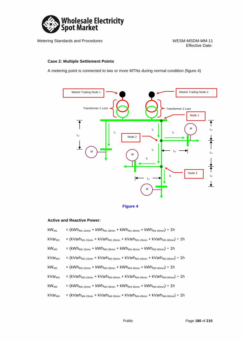
Metering Standards and Procedures WESM-MSDM-MM-11 Effective Date:
Public Page 180 of 210
Case 2: Multiple Settlement Points
A metering point is connected to two or more MTNs during normal condition (figure 4)
Figure 4
Active and Reactive Power: kWM1 = (kWhM1-15min + kWhM1-30min + kWhM1-45min + kWhM1-00min) ÷ 1h kVarM1 = (kVarhM1-15min + kVarhM1-30min + kVarhM1-45min + kVarhM1-00min) ÷ 1h kWM2 = (kWhM2-15min + kWhM2-30min + kWhM2-45min + kWhM2-00min) ÷ 1h kVarM2 = (kVarhM2-15min + kVarhM2-30min + kVarhM2-45min + kVarhM2-00min) ÷ 1h kWM3 = (kWhM3-15min + kWhM3-30min + kWhM3-45min + kWhM3-00min) ÷ 1h kVarM3 = (kVarhM3-15min + kVarhM3-30min + kVarhM3-45min + kVarhM3-00min) ÷ 1h kWM4 = (kWhM4-15min + kWhM4-30min + kWhM4-45min + kWhM4-00min) ÷ 1h kVarM4 = (kVarhM4-15min + kVarhM4-30min + kVarhM4-45min + kVarhM4-00min) ÷ 1h
Market Trading Node 1
L2
L4
L6
L4
L5
I1 I2
I3
I4
I5
I6
Node 1
Node 3
Market Trading Node 2
M
1
M
4
M
2
M
3
Transformer 2 Loss Transformer 1 Loss
L3
Node 2
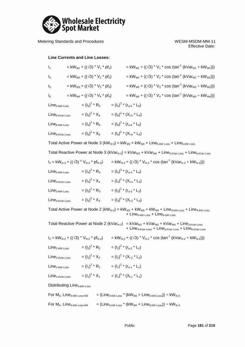
Metering Standards and Procedures WESM-MSDM-MM-11 Effective Date:
Public Page 181 of 210
Line Currents and Line Losses: I1 = kWM1 ÷ ((√3) * V1 * pf1) = kWM1 ÷ ((√3) * V1 * cos (tan
-1 (kVarM1 ÷ kWM1)))
I3 = kWM2 ÷ ((√3) * V2 * pf2) = kWM2 ÷ ((√3) * V2 * cos (tan
-1 (kVarM2 ÷ kWM2)))
I5 = kWM3 ÷ ((√3) * V3 * pf3) = kWM3 ÷ ((√3) * V3 * cos (tan
-1 (kVarM3 ÷ kWM3)))
I6 = kWM4 ÷ ((√3) * V4 * pf4) = kWM4 ÷ ((√3) * V4 * cos (tan
-1 (kVarM4 ÷ kWM4)))
Line5-kW-Loss = (I5)
2 * R5 = (I5)
2 * (ra-5 * L5)
Line5-kVar-Loss = (I5)
2 * X5 = (I5)
2 * (Xl-5 * L5)
Line6-kW-Loss = (I6)
2 * R6 = (I6)
2 * (ra-6 * L6)
Line6-kVar-Loss = (I6)
2 * X6 = (I6)
2 * (Xl-6 * L6)
Total Active Power at Node 3 (kWN-3) = kWM3 + kWM4 + Line5-kW-Loss + Line6-kW-Loss
Total Reactive Power at Node 3 (kVarN-3) = kVarM3 + kVarM4 + Line5-kVar-Loss + Line6-kVar-Loss
I4 = kWN-3 ÷ ((√3) * VN-3 * pfN-3) = kWN-3 ÷ ((√3) * VN-3 * cos (tan
-1 (kVarN-3 ÷ kWN-3)))
Line4-kW-Loss = (I4)
2 * R4 = (I4)
2 * (ra-4 * L4)
Line4-kVar-Loss = (I4)
2 * X4 = (I4)
2 * (Xl-4 * L4)
Line3-kW-Loss = (I3)
2 * R3 = (I3)
2 * (ra-3 * L3)
Line3-kVar-Loss = (I3)
2 * X3 = (I3)
2 * (Xl-3 * L3)
Total Active Power at Node 2 (kWN-2) = kWM2 + kWM3 + kWM4 + Line3-kW-Loss + Line4-kW-Loss + Line5-kW-Loss + Line6-kW-Loss
Total Reactive Power at Node 2 (kVarN-2) = kVarM2 + kVarM3 + kVarM4 + Line3-kVar-Loss + Line4-kVar-Loss + Line5-kVar-Loss + Line6-kVar-Loss
I2 = kWN-2 ÷ ((√3) * VN-2 * pfN-2) = kWN-2 ÷ ((√3) * VN-2 * cos (tan
-1 (kVarN-2 ÷ kWN-2)))
Line2-kW-Loss = (I2)
2 * R2 = (I2)
2 * (ra-2 * L2)
Line2-kVar-Loss = (I2)
2 * X2 = (I2)
2 * (Xl-2 * L2)
Line1-kW-Loss = (I1)
2 * R1 = (I1)
2 * (ra-1 * L1)
Line1-kVar-Loss = (I1)
2 * X1 = (I1)
2 * (Xl-1 * L1)
Distributing Line4-kW-Loss For M3, Line4-kW-Loss-M3 = (Line4-kW-Loss * (kWM3 + Line5-kW-Loss)) ÷ kWN-3 For M4, Line4-kW-Loss-M4 = (Line4-kW-Loss * (kWM4 + Line6-kW-Loss)) ÷ kWN-3

Metering Standards and Procedures WESM-MSDM-MM-11 Effective Date:
Public Page 182 of 210
Distributing Line2-kW-Loss For M2, Line2-kW-Loss-M2 = (Line2-kW-Loss * (kWM2 + Line3-kW-Loss)) ÷ kWN-2 For M3, Line2-kW-Loss-M3 = (Line2-kW-Loss * (kWM3 + Line5-kW-Loss + Line4-kW-Loss-M3)) ÷ kWN-2 For M4, Line2-kW-Loss-M4 = (Line2-kW-Loss * (kWM4 + Line6-kW-Loss + Line4-kW-Loss-M4)) ÷ kWN-2 Transformer Losses: T1CoreLoss-M1 = T1CoreLoss * (kWM1 ÷ )
T1CoreLoss-M2 = T1CoreLoss * (kWM2 ÷ ) T1CoreLoss-M3 = T1CoreLoss * (kWM3 ÷ ) T1CoreLoss-M4 = T1CoreLoss * (kWM4 ÷ ) T1CopperLoss = (((kWN-1 ÷ 2) ÷ pfN-1) ÷ T1kVA-Rating))
2 * PShort-Circuit-T1
T1CopperLoss-M1 = T1CopperLoss * (kWM1 + Line1-kW-Loss) ÷ kWN-1 T1CopperLoss-M2 = T1CopperLoss * (kWM2 + Line3-kW-Loss + Line2-kW-Loss-M2) ÷ kWN-1 T1CopperLoss-M3 = T1CopperLoss * (kWM3 + Line5-kW-Loss + Line4-kW-Loss-M3 + Line4-kW-Loss-M3) ÷
kWN-1 T1CopperLoss-M4 = T1CopperLoss * (kWM4 + Line5-kW-Loss + Line4-kW-Loss-M4 + Line4-kW-Loss-M4) ÷
kWN-1 T2CoreLoss-M1 = T2CoreLoss * (kWM1 ÷ )
T2CoreLoss-M2 = T2CoreLoss * (kWM2 ÷ ) T2CoreLoss-M3 = T2CoreLoss * (kWM3 ÷ ) T2CoreLoss-M4 = T2CoreLoss * (kWM4 ÷ ) T2CopperLoss = (((kWN-1 ÷ 2) ÷ pfN-1) ÷ T2kVA-Rating))
2 * PShort-Circuit-T2
T2CopperLoss-M1 = T2CopperLoss * (kWM1 + Line1-kW-Loss) ÷ kWN-1 T2CopperLoss-M2 = T2CopperLoss * (kWM2 + Line3-kW-Loss + Line2-kW-Loss-M2) ÷ kWN-1 T2CopperLoss-M3 = T2CopperLoss * (kWM3 + Line5-kW-Loss + Line4-kW-Loss-M3 + Line4-kW-Loss-M3) ÷
kWN-1 T2CopperLoss-M4 = T2CopperLoss * (kWM4 + Line5-kW-Loss + Line4-kW-Loss-M4 + Line4-kW-Loss-M4) ÷
kWN-1 Total Active Loss for each Meter:
n
∑
kWMi
i =1
n
∑
kWMi
i =1
n
∑
kWMi
i =1
n
∑
kWMi
i =1
n
∑
kWMi
i =1
n
∑
kWMi
i =1
n
∑
kWMi
i =1
n
∑
kWMi
i =1

Metering Standards and Procedures WESM-MSDM-MM-11 Effective Date:
Public Page 183 of 210
TotalkW-Loss-M1 = Line1-kW-Loss + T1CoreLoss-M1 + T1CopperLoss-M1 + T2CoreLoss-M1 +
T2CopperLoss-M1 TotalkW-Loss-M2 = Line3-kW-Loss + Line2-kW-Loss-M2 + T1CoreLoss-M2 + T1CopperLoss-M2 + T2CoreLoss-M2 + T2CopperLoss-M2 TotalkW-Loss-M3 = Line5-kW-Loss + Line4-kW-Loss-M3 + Line2-kW-Loss-M3 + T1CoreLoss-M3 + T1CopperLoss-M3 + T2CoreLoss-M3 + T2CopperLoss-M3 TotalkW-Loss-M4 = Line6-kW-Loss + Line4-kW-Loss-M4 + Line2-kW-Loss-M4 + T1CoreLoss-M4 + T1CopperLoss-M4 + T2CoreLoss-M4 + T2CopperLoss-M4 SSLF: SSLFM1 = 1 + (TotalkW-Loss-M1 ÷ kWM1) SSLFM2 = 1 + (TotalkW-Loss-M2 ÷ kWM2) SSLFM3 = 1 + (TotalkW-Loss-M3 ÷ kWM3) SSLFM4 = 1 + (TotalkW-Loss-M4 ÷ kWM4) Adjusted Active Power: AdjustedkW-M1 = TotalkW-Loss-M1 + kWM1 AdjustedkW-M2 = TotalkW-Loss-M2 + kWM2 AdjustedKW-M3 = TotalkW-Loss-M3 + kWM3 AdjustedkW-M4 = TotalkW-Loss-M4 + kWM4

Metering Standards and Procedures WESM-MSDM-MM-11 Effective Date:
Public Page 184 of 210
Case 3: Alternate Settlement Points: A metering point is connected to another MTN for alternate source of power during emergency condition or pre-arranged shutdown
a. Case 3 – A: a metering point is connected to another transformer for alternate source of power during emergency or pre-arranged shutdown. Usual setting for alternate source of power from the same substation (figure 5).
Figure 5 At normal condition (figure 5), SSLF of the meters connected to each defined point of sale can be computed separately treated the same as Case 1 – A (for T1) and Case 1 – B (for T2). At Normal Condition for T1:
Active and Reactive Power: kWM1 = (kWhM1-15min + kWhM1-30min + kWhM1-45min + kWhM1-00min) ÷ 1h kVarM1 = (kVarhM1-15min + kVarhM1-30min + kVarhM1-45min + kVarhM1-00min) ÷ 1h
M
1
Market Trading Node 1
L2
L4
L6
L1
L5
I1 I2
I3
I4
I5
I6
Node 1
Node 3
Market Trading Node 2
M
4
M
2
M
3
Transformer 2 Loss Transformer 1 Loss
Node 2

Metering Standards and Procedures WESM-MSDM-MM-11 Effective Date:
Public Page 185 of 210
Line Current and Line Loss
I1 = kWM1 ÷ ((√3) * V1 * pf1) Line1-kW-Loss = (I1)
2 * R1 = (I1)
2 * (ra-1 * L1)
Transformer Losses T1CoreLoss-M1 = T1CoreLoss ÷ 1 T1CopperLoss-M1 = ((kWM1 ÷ pf1) ÷ T1kVA-Rating)
2 * PShort-Circuit-T1
Total Active Loss TotalkW-Loss-M1 = Line1-kW-Loss + T1CoreLoss-M1 + T1CopperLoss-M1 SSLF
SSLF M1 = 1 + (TotalkW-Loss-M1 ÷ kWM1) Adjusted Active Power: AdjustedkW-M1 = TotalkW-Loss-M1 + kWM1
At Normal Condition for T2:
Active and Reactive Power: kWM2 = (kWhM2-15min + kWhM2-30min + kWhM2-45min + kWhM2-00min) ÷ 1h kVarM2 = (kVarhM2-15min + kVarhM2-30min + kVarhM2-45min + kVarhM2-00min) ÷ 1h kWM3 = (kWhM3-15min + kWhM3-30min + kWhM3-45min + kWhM3-00min) ÷ 1h kVarM3 = (kVarhM3-15min + kVarhM3-30min + kVarhM3-45min + kVarhM3-00min) ÷ 1h kWM4 = (kWhM4-15min + kWhM4-30min + kWhM4-45min + kWhM4-00min) ÷ 1h kVarM4 = (kVarhM4-15min + kVarhM4-30min + kVarhM4-45min + kVarhM4-00min) ÷ 1h Line Currents and Line Losses: I3 = kWM2 ÷ ((√3) * V2 * pf2) = kWM2 ÷ ((√3) * V2 * cos (tan
-1 (kVarM2 ÷ kWM2)))
I5 = kWM3 ÷ ((√3) * V3 * pf3) = kWM3 ÷ ((√3) * V3 * cos (tan
-1 (kVarM3 ÷ kWM3)))
I6 = kWM4 ÷ ((√3) * V4 * pf4) = kWM4 ÷ ((√3) * V4 * cos (tan
-1 (kVarM4 ÷ kWM4)))

Metering Standards and Procedures WESM-MSDM-MM-11 Effective Date:
Public Page 186 of 210
Line5-kW-Loss = (I5)2 * R5 = (I5)
2 * (ra-5 * L5)
Line5-kVar-Loss = (I5)
2 * X5 = (I5)
2 * (Xl-5 * L5)
Line6-kW-Loss = (I6)
2 * R6 = (I6)
2 * (ra-6 * L6)
Line6-kVar-Loss = (I6)
2 * X6 = (I6)
2 * (Xl-6 * L6)
Total Active Power at Node 3 (kWN-3) = kWM3 + kWM4 + Line5-kW-Loss + Line6-kW-Loss
Total Reactive Power at Node 3 (kVarN-3) = kVarM3 + kVarM4 + Line5-kVar-Loss + Line6-kVar-Loss
I4 = kWN-3 ÷ ((√3) * VN-3 * pfN-3) = kWN-3 ÷ ((√3) * VN-3 * cos (tan
-1 (kVarN-3 ÷ kWN-3)))
Line4-kW-Loss = (I4)
2 * R4 = (I4)
2 * (ra-4 * L4)
Line4-kVar-Loss = (I4)
2 * X4 = (I4)
2 * (Xl-4 * L4)
Line3-kW-Loss = (I3)
2 * R3 = (I3)
2 * (ra-3 * L3)
Line3-kVar-Loss = (I3)
2 * X3 = (I3)
2 * (Xl-3 * L3)
Total Active Power at Node 2 (kWN-2) = kWM2 + kWM3 + kWM4 + Line3-kWLoss + Line4-kW-Loss + Line5-kW-Loss + Line6-kW-Loss
Total Reactive Power at Node 2 (kVarN-2) = kVarM2 + kVarM3 + kVarM4 + Line3-kVar-Loss + Line4-kVar-Loss + Line5-kVar-Loss + Line6-kVar-Loss
I2 = kWN-2 ÷ ((√3) * VN-2 * pfN-2) = kWN-2 ÷ ((√3) * VN-2 * cos (tan
-1 (kVarN-2 ÷ kWN-2)))
Line2-kW-Loss = (I2)
2 * R2 = (I2)
2 * (ra-2 * L2)
Line2-kVar-Loss = (I2)
2 * X2 = (I2)
2 * (xl-2 * L2)
Distributing Line4-kWLoss For M3, Line4-kW-Loss-M3 = (Line4-kW-Loss * (kWM3 + Line5-kW-Loss)) ÷ kWN-3 For M4, Line4-kW-Loss-M4 = (Line4-kW-Loss * (kWM4 + Line6-kW-Loss)) ÷ kWN-3 Distributing Line2-kW-Loss For M2, Line2-kW-Loss-M2 = (Line2-kW-Loss * (kWM2 + Line3-kW-Loss)) ÷ kWN-2 For M3, Line2-kW-Loss-M3 = (Line2-kW-Loss * (kWM3 + Line5-kW-Loss + Line4-kW-Loss-M3)) ÷ kWN-2 For M4, Line2-kW-Loss-M4 = (Line2-kW-Loss * (kWM4 + Line6-kW-Loss + Line4-kW-Loss-M4)) ÷ kWN-2
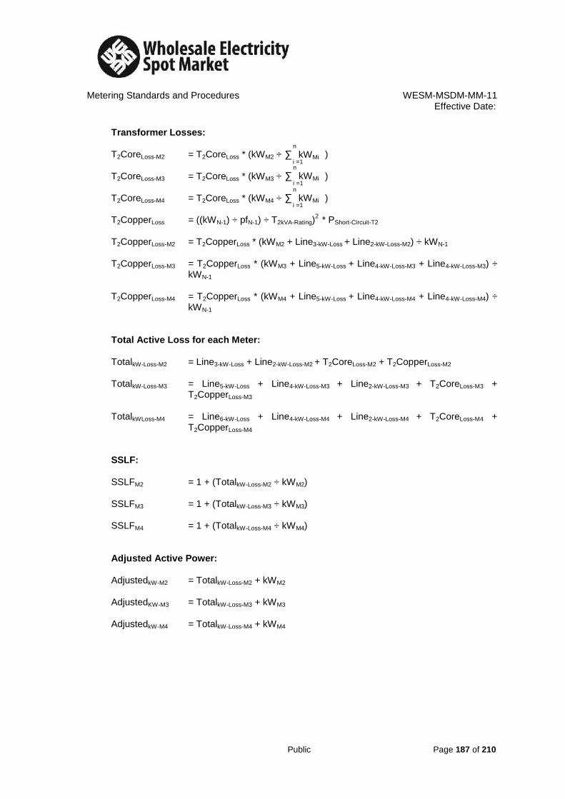
Metering Standards and Procedures WESM-MSDM-MM-11 Effective Date:
Public Page 187 of 210
Transformer Losses: T2CoreLoss-M2 = T2CoreLoss * (kWM2 ÷ ) T2CoreLoss-M3 = T2CoreLoss * (kWM3 ÷ ) T2CoreLoss-M4 = T2CoreLoss * (kWM4 ÷ ) T2CopperLoss = ((kWN-1) ÷ pfN-1) ÷ T2kVA-Rating)
2 * PShort-Circuit-T2
T2CopperLoss-M2 = T2CopperLoss * (kWM2 + Line3-kW-Loss + Line2-kW-Loss-M2) ÷ kWN-1 T2CopperLoss-M3 = T2CopperLoss * (kWM3 + Line5-kW-Loss + Line4-kW-Loss-M3 + Line4-kW-Loss-M3) ÷
kWN-1 T2CopperLoss-M4 = T2CopperLoss * (kWM4 + Line5-kW-Loss + Line4-kW-Loss-M4 + Line4-kW-Loss-M4) ÷
kWN-1 Total Active Loss for each Meter: TotalkW-Loss-M2 = Line3-kW-Loss + Line2-kW-Loss-M2 + T2CoreLoss-M2 + T2CopperLoss-M2 TotalkW-Loss-M3 = Line5-kW-Loss + Line4-kW-Loss-M3 + Line2-kW-Loss-M3 + T2CoreLoss-M3 +
T2CopperLoss-M3 TotalkWLoss-M4 = Line6-kW-Loss + Line4-kW-Loss-M4 + Line2-kW-Loss-M4 + T2CoreLoss-M4 +
T2CopperLoss-M4 SSLF: SSLFM2 = 1 + (TotalkW-Loss-M2 ÷ kWM2) SSLFM3 = 1 + (TotalkW-Loss-M3 ÷ kWM3) SSLFM4 = 1 + (TotalkW-Loss-M4 ÷ kWM4) Adjusted Active Power: AdjustedkW-M2 = TotalkW-Loss-M2 + kWM2 AdjustedKW-M3 = TotalkW-Loss-M3 + kWM3 AdjustedkW-M4 = TotalkW-Loss-M4 + kWM4
n
∑
kWMi
i =1 n
∑
kWMi
i =1
n
∑
kWMi
i =1
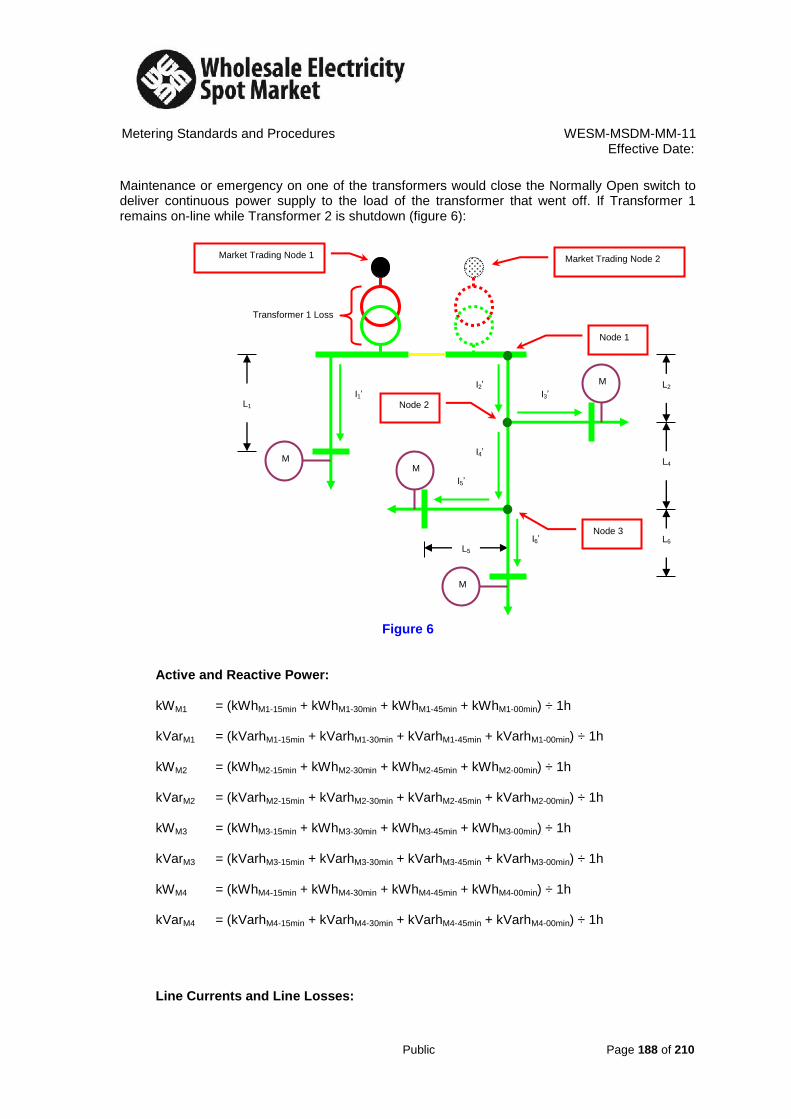
Metering Standards and Procedures WESM-MSDM-MM-11 Effective Date:
Public Page 188 of 210
Maintenance or emergency on one of the transformers would close the Normally Open switch to deliver continuous power supply to the load of the transformer that went off. If Transformer 1 remains on-line while Transformer 2 is shutdown (figure 6):
Figure 6 Active and Reactive Power: kWM1 = (kWhM1-15min + kWhM1-30min + kWhM1-45min + kWhM1-00min) ÷ 1h kVarM1 = (kVarhM1-15min + kVarhM1-30min + kVarhM1-45min + kVarhM1-00min) ÷ 1h kWM2 = (kWhM2-15min + kWhM2-30min + kWhM2-45min + kWhM2-00min) ÷ 1h kVarM2 = (kVarhM2-15min + kVarhM2-30min + kVarhM2-45min + kVarhM2-00min) ÷ 1h kWM3 = (kWhM3-15min + kWhM3-30min + kWhM3-45min + kWhM3-00min) ÷ 1h kVarM3 = (kVarhM3-15min + kVarhM3-30min + kVarhM3-45min + kVarhM3-00min) ÷ 1h kWM4 = (kWhM4-15min + kWhM4-30min + kWhM4-45min + kWhM4-00min) ÷ 1h kVarM4 = (kVarhM4-15min + kVarhM4-30min + kVarhM4-45min + kVarhM4-00min) ÷ 1h
Line Currents and Line Losses:
M
1
Market Trading Node 1
L2
L4
L6
L1
L5
I1’ I2’
I3’
I4’
I5’
I6’
Node 1
Node 3
Market Trading Node 2
M
4
M
2
M
3
Transformer 1 Loss
Node 2

Metering Standards and Procedures WESM-MSDM-MM-11 Effective Date:
Public Page 189 of 210
I1 = kWM1 ÷ ((√3) * V1 * pf1) = kWM1 ÷ ((√3) * V1 * cos (tan
-1 (kVarM1 ÷ kWM1)))
I3 = kWM2 ÷ ((√3) * V2 * pf2) = kWM2 ÷ ((√3) * V2 * cos (tan
-1 (kVarM2 ÷ kWM2)))
I5 = kWM3 ÷ ((√3) * V3 * pf3) = kWM3 ÷ ((√3) * V3 * cos (tan
-1 (kVarM3 ÷ kWM3)))
I6 = kWM4 ÷ ((√3) * V4 * pf4) = kWM4 ÷ ((√3) * V4 * cos (tan
-1 (kVarM4 ÷ kWM4)))
Line5-kW-Loss = (I5)
2 * R5 = (I5)
2 * (ra-5 * L5)
Line5-kVa-rLoss = (I5)
2 * X5 = (I5)
2 * (Xl-5 * L5)
Line6-kW-Loss = (I6)
2 * R6 = (I6)
2 * (ra-6 * L6)
Line6-kVar-Loss = (I6)
2 * X6 = (I6)
2 * (Xl-6 * L6)
Total Active Power at Node 3 (kWN-3) = kWM3 + kWM4 + Line5-kW-Loss + Line6-kW-Loss
Total Reactive Power at Node 3 (kVarN-3) = kVarM3 + kVarM4 + Line5-kVar-Loss + Line6-kVar-Loss
I4 = kWN-3 ÷ ((√3) * VN-3 * pfN-3) = kWN-3 ÷ ((√3) * VN-3 * cos (tan
-1 (kVarN-3 ÷ kWN-3)))
Line4-kW-Loss = (I4)
2 * R4 = (I4)
2 * (ra-4 * L4)
Line4-kVar-Loss = (I4)
2 * X4 = (I4)
2 * (Xl-4 * L4)
Line3-kW-Loss = (I3)
2 * R3 = (I3)
2 * (ra-3 * L3)
Line3-kVar-Loss = (I3)
2 * X3 = (I3)
2 * (Xl-3 * L3)
Total Active Power at Node 2 (kWN-2) = kWM2 + kWM3 + kWM4 + Line3-kW-Loss + Line4-kW-Loss + Line5-kW-Loss + Line6-kW-Loss Total Reactive Power at Node 2 (kVarN-2) = kVarM2 + kVarM3 + kVarM4 + Line3-kVar-Loss + Line4-kVar-Loss + Line5-kVar-Loss + Line6-kVar-Loss I2 = kWN-2 ÷ ((√3) * VN-2 * pfN-2) = kWN-2 ÷ ((√3) * VN-2 * cos (tan
-1 (kVarN-2 ÷ kWN-2)))
Line2-kW-Loss = (I2)
2 * R2 = (I2)
2 * (ra-2 * L2)
Line2-kVar-Loss = (I2)
2 * X2 = (I2)
2 * (Xl-2 * L2)
Line1-kW-Loss = (I1)
2 * R2 = (I1)
2 * (ra-2 * L2)
Line1-kVar-Loss = (I1)
2 * X2 = (I1)
2 * (Xl-2 * L2)
Distributing Line4-kW-Loss For M3, Line4-kW-Loss-M3 = (Line4-kW-Loss * (kWM3 + Line5-kW-Loss)) ÷ kWN-3 For M4, Line4-kW-Loss-M4 = (Line4-kW-Loss * (kWM4 + Line6-kW-Loss)) ÷ kWN-3

Metering Standards and Procedures WESM-MSDM-MM-11 Effective Date:
Public Page 190 of 210
Distributing Line2-kW-Loss For M2, Line2-kW-Loss-M2 = (Line2-kW-Loss * (kWM2 + Line3-kW-Loss)) ÷ kWN-2 For M3, Line2-kW-Loss-M3 = (Line2-kW-Loss * (kWM3 + Line5-kW-Loss + Line4-kW-LossM3)) ÷ kWN-2 For M4, Line2-kW-Loss-M4 = (Line2-kW-Loss * (kWM4 + Line6-kW-Loss + Line4-kW-LossM4)) ÷ kWN-2 Transformer Losses: T1CoreLoss-M1 = T1CoreLoss * (kWM1 ÷ )
T1CoreLoss-M2 = T1CoreLoss * (kWM2 ÷ ) T1CoreLoss-M3 = T1CoreLoss * (kWM3 ÷ ) T1CoreLoss-M4 = T1CoreLoss * (kWM4 ÷ ) T1CopperLoss = ((kWN-1) ÷ pfN-1) ÷ T1kVA-Rating)
2 * PShort-Circuit-T1
T1CopperLoss-M1 = T1CopperLoss * (kWM1 + Line1-kW-Loss) ÷ kWN-1 T1CopperLoss-M2 = T1CopperLoss * (kWM2 + Line3-kW-Loss + Line2-kW-Loss-M2) ÷ kWN-1 T1CopperLoss-M3 = T1CopperLoss * (kWM3 + Line5-kW-Loss + Line4-kW-Loss-M3 + Line2-kW-Loss-M3) ÷
kWN-1 T1CopperLoss-M4 = T1CopperLoss * (kWM4 + Line6-kW-Loss + Line4-kW-Loss-M4 + Line2-kW-Loss-M4) ÷
kWN-1 Total Active Loss for each Meter: TotalkW-Loss-M1 = Line1-kW-Loss + T1CoreLoss-M1 + T1CopperLoss-M1 TotalkW-Loss-M2 = Line3-kW-Loss + Line2-kWLoss-M2 + T1CoreLoss-M2 + T1CopperLoss-M2 TotalkW-Loss-M3 = Line5-kW-Loss + Line4-kW-Loss-M3 + Line2-kW-Loss-M3 + T1CoreLoss-M3 +
T1CopperLoss-M3 TotalkW-Loss-M4 = Line6-kW-Loss + Line4-kW-Loss-M4 + Line2-kW-Loss-M4 + T1CoreLoss-M4 +
T1CopperLoss-M4 SSLF: SSLFM1 = 1 + (TotalkW-Loss-M1 ÷ kWM1) SSLFM2 = 1 + (TotalkW-Loss-M2 ÷ kWM2) SSLFM3 = 1 + (TotalkW-Loss-M3 ÷ kWM3) SSLFM4 = 1 + (TotalkW-Loss-M4 ÷ kWM4)
n
∑
kWMi
i =1
n
∑
kWMi
i =1
n
∑
kWMi
i =1
n
∑
kWMi
i =1

Metering Standards and Procedures WESM-MSDM-MM-11 Effective Date:
Public Page 191 of 210
Adjusted Active Power: AdjustedkW-M1 = TotalkW-Loss-M1 + kWM1 AdjustedkW-M2 = TotalkW-Loss-M2 + kWM2 AdjustedKW-M3 = TotalkW-Loss-M3 + kWM3 AdjustedkW-M4 = TotalkW-Loss-M4 + kWM4
If Transformer 1 is shutdown while Transformer 2 remains on-line (figure 7), the manner of computation is the same, only, it is the core loss and full-load copper loss of Transformer 2 that would be distributed.
Figure 7
Market Trading Node 1
L2
L4
L6
L1
L5
I1” I2”
I3”
I4”
I5”
I6”
Node 1
Node 3
Market Trading Node 2
M
1
M
4
M
2
M
3
Transformer 2 Loss
Node 2

Metering Standards and Procedures WESM-MSDM-MM-11 Effective Date:
Public Page 192 of 210
b. Case 3 – B: a metering point is connected to another line for alternate source of power during emergency or pre-arranged shutdown. This is the usual setting for alternate source of power from another substation (figure 8).
Figure 8
At normal condition (figure 8), SSLF of the meters connected to each MTN can be computed separately treated the same as in Case 1 – A (for T2) and Case 1 – B (for T1). At Normal Condition for T1:
Active and Reactive Power: kWM1 = (kWhM1-15min + kWhM1-30min + kWhM1-45min + kWhM1-00min) ÷ 1h kVarM1 = (kVarhM1-15min + kVarhM1-30min + kVarhM1-45min + kVarhM1-00min) ÷ 1h kWM2 = (kWhM2-15min + kWhM2-30min + kWhM2-45min + kWhM2-00min) ÷ 1h kVarM2 = (kVarhM2-15min + kVarhM2-30min + kVarhM2-45min + kVarhM2-00min) ÷ 1h kWM3 = (kWhM3-15min + kWhM3-30min + kWhM3-45min + kWhM3-00min) ÷ 1h
M
5
Node 1
Node 3
Node 2
I2 I3 I7
M
1
M
4
M
2
M
3
L1
L5
I1
I4
I5
I6
Market Trading Node 1
L11
L7 I6
L2
L4
L6
L10 L3
Transformer 2 Loss Transformer 1 Loss
L9 L8
Market Trading Node 2
N.C.

Metering Standards and Procedures WESM-MSDM-MM-11 Effective Date:
Public Page 193 of 210
kVarM3 = (kVarhM3-15min + kVarhM3-30min + kVarhM3-45min + kVarhM3-00min) ÷ 1h kWM4 = (kWhM4-15min + kWhM4-30min + kWhM4-45min + kWhM4-00min) ÷ 1h kVarM4 = (kVarhM4-15min + kVarhM4-30min + kVarhM4-45min + kVarhM4-00min) ÷ 1h Line Currents and Line Losses: I1 = kWM1 ÷ ((√3) * V1 * pf1) = kWM1 ÷ ((√3) * V1 * cos (tan
-1 (kVarM1 ÷ kWM1)))
I3 = kWM2 ÷ ((√3) * V2 * pf2) = kWM2 ÷ ((√3) * V2 * cos (tan
-1 (kVarM2 ÷ kWM2)))
I5 = kWM3 ÷ ((√3) * V3 * pf3) = kWM3 ÷ ((√3) * V3 * cos (tan
-1 (kVarM3 ÷ kWM3)))
I6 = kWM4 ÷ ((√3) * V4 * pf4) = kWM4 ÷ ((√3) * V4 * cos (tan
-1 (kVarM4 ÷ kWM4)))
Line5-kW-Loss = (I5)
2 * R5 = (I5)
2 * (ra-5 * L5)
Line5-kVar-Loss = (I5)
2 * X5 = (I5)
2 * (Xl-5 * L5)
Line6-kW-Loss = (I6)
2 * R6 = (I6)
2 * (ra-6 * L6)
Line6-kVar-Loss = (I6)
2 * X6 = (I6)
2 * (Xl-6 * L6)
Line7-kW-Loss = (I6)
2 * R7 = (I6)
2 * (ra-7 * L7)
Line7-kVar-Loss = (I6)
2 * X7 = (I6)
2 * (Xl-7 * L7)
Total Active Power at Node 3 (kWN-3) = kWM3 + kWM4 + Line5-kW-Loss + Line6-kW-Loss + Line7-kW-Loss
Total Reactive Power at Node 3 (kVarN-3) = kVarM3 + kVarM4 + Line5-kVar-Loss + Line6-kVar-Loss + Line7-kVar-Loss
I4 = kWN-3 ÷ ((√3) * VN-3 * pfN-3) = kWN-3 ÷ ((√3) * VN-3 * cos (tan
-1 (kVarN-3 ÷ kWN-3)))
Line4-kW-Loss = (I4)
2 * R4 = (I4)
2 * (ra-4 * L4)
Line4-kVar-Loss = (I4)
2 * X4 = (I4)
2 * (Xl-4 * L4)
Line3-kW-Loss = (I3)
2 * R3 = (I3)
2 * (ra-3 * L3)
Line3-kVar-Loss = (I3)
2 * X3 = (I3)
2 * (Xl-3 * L3)
Total Active Power at Node 2 (kWN-2) = kWM2 + kWM3 + kWM4 + Line3-kW-Loss + Line4-kW-Loss + Line5-kW-Loss + Line6-kW-Loss + Line7-kW-Loss
Total Reactive Power at Node 2 (kVarN-2) = kVarM2 + kVarM3 + kVarM4 + Line3-kVar-Loss
+ Line4-kVar-Loss + Line5-kVar-Loss + Line6-kVar-Loss + Line7-kVar-Loss
I2 = kWN-2 ÷ ((√3) * VN-2 * pfN-2) = kWN-2 ÷ ((√3) * VN-2 * cos (tan
-1 (kVarN-2 ÷ kWN-2)))
Line2-kW-Loss = (I2)
2 * R2 = (I2)
2 * (ra-2 * L2)

Metering Standards and Procedures WESM-MSDM-MM-11 Effective Date:
Public Page 194 of 210
Line2-kVar-Loss = (I2)
2 * X2 = (I2)
2 * (Xl-2 * L2)
Line1-kW-Loss = (I1)
2 * R2 = (I1)
2 * (ra-2 * L2)
Line1-kVar-Loss = (I1)
2 * X2 = (I1)
2 * (Xl-2 * L2)
Distributing Line4-kW-Loss For M3, Line4-kW-Loss-M3 = (Line4-kW-Loss * (kWM3 + Line5-kW-Loss)) ÷ kWN-3 For M4, Line4-kW-Loss-M4 = (Line4-kW-Loss * (kWM4 + Line6-kW-Loss + Line7-kW-Loss)) ÷ kWN-3 Distributing Line2-kW-Loss For M2, Line2-kW-Loss-M2 = (Line2-kW-Loss * (kWM2 + Line3-kW-Loss)) ÷ kWN-2 For M3, Line2-kW-Loss-M3 = (Line2-kW-Loss * (kWM3 + Line5-kW-Loss + Line4-kW-Loss-M3)) ÷ kWN-2 For M4, Line2-kW-Loss-M4 = (Line2-kW-Loss * (kWM4 + Line6-kW-Loss + Line7-kW-Loss + Line4-kW-Loss-M4)) ÷ kWN-2 Transformer Losses: T1CoreLoss-M1 = T1CoreLoss * (kWM1 ÷ )
T1CoreLoss-M2 = T1CoreLoss * (kWM2 ÷ ) T1CoreLoss-M3 = T1CoreLoss * (kWM3 ÷ ) T1CoreLoss-M4 = T1CoreLoss * (kWM4 ÷ ) T1CopperLoss = (((kWN-1 ÷ 2) ÷ pfN-1) ÷ T1kVA-Rating)
2 * PShort-Circuit-T1
T1CopperLoss-M1 = T1CopperLoss * (kWM1 + Line1-kW-Loss) ÷ kWN-1 T1CopperLoss-M2 = T1CopperLoss * (kWM2 + Line3-kW-Loss + Line2-kW-Loss-M2) ÷ kWN-1 T1CopperLoss-M3 = T1CopperLoss * (kWM3 + Line5-kW-Loss + Line4-kW-Loss-M3 + Line2-kW-Loss-M3) ÷
kWN-1 T1CopperLoss-M4 = T1CopperLoss * (kWM4 + Line6-kW-Loss + Line7-kW-Loss + Line4-kW-Loss-M4 + Line2-kW-Loss-M4) ÷ kWN-1 Total Loss for each Meter: TotalkW-Loss-M1 = Line1-kW-Loss + T1CoreLoss-M1 + T1CopperLoss-M1 TotalkW-Loss-M2 = Line3-kW-Loss + Line2-kWLoss-M2 + T1CoreLoss-M2 + T1CopperLoss-M2
n
∑
kWMi
i =1
n
∑
kWMi
i =1
n
∑
kWMi
i =1
n
∑
kWMi
i =1

Metering Standards and Procedures WESM-MSDM-MM-11 Effective Date:
Public Page 195 of 210
TotalkW-Loss-M3 = Line5-kW-Loss + Line4-kW-Loss-M3 + Line2-kW-Loss-M3 + T1CoreLoss-M3 + T1CopperLoss-M3 TotalkW-Loss-M4 = Line6-kW-Loss + Line7-kW-Loss +Line4-kW-Loss-M4 + Line2-kW-Loss-M4 + T1CoreLoss-M4 + T1CopperLoss-M4 SSLF
SSLFM1 = 1 + (TotalkW-Loss-M1 ÷ kWM1) SSLFM2 = 1 + (TotalkW-Loss-M2 ÷ kWM2) SSLFM3 = 1 + (TotalkW-Loss-M3 ÷ kWM3) SSLFM4 = 1 + (TotalkW-Loss-M4 ÷ kWM4)
Adjusted Active Power: AdjustedkW-M1 = TotalkW-Loss-M1 + kWM1 AdjustedkW-M2 = TotalkW-Loss-M2 + kWM2 AdjustedKW-M3 = TotalkW-Loss-M3 + kWM3 AdjustedkW-M4 = TotalkW-Loss-M4 + kWM4
At Normal Condition for T2:
Active and Reactive Power: kWM5 = (kWhM5-15min + kWhM5-30min + kWhM5-45min + kWhM5-00min) ÷ 1h kVarM5 = (kVarhM5-15min + kVarhM5-30min + kVarhM5-45min + kVarhM5-00min) ÷ 1h Line Current and Line Loss I7 = kWM5 ÷ ((√3) * V5 * pf5) Line11-kW-Loss = (I7)
2 * R11 = (I7)
2 * (ra-11 * L11)
Transformer Losses T2CoreLoss-M5 = T2CoreLoss ÷ 1 T2CopperLoss-M5 = ((kWM5 ÷ pf5) ÷ T2kVA-Rating)
2 * PShort-Circuit-T2
Total Active Loss for the Meter

Metering Standards and Procedures WESM-MSDM-MM-11 Effective Date:
Public Page 196 of 210
TotalkW-Loss-M5 = Line11-kW-Loss + T2CoreLoss + T2CopperLoss-M5 SSLF SSLFM5 = 1 + (TotalkW-Loss-M5 ÷ kWM5) Adjusted Active Power: AdjustedkW-M5 = TotalkW-Loss-M5 + kWM5
Maintenance or emergency on the line would close the Normally Open switch to deliver continuous power supply to the load of the line that went off. If Transformer 1 remains on-line while Transformer 2 is shutdown (figure 9):
Figure 9
Active and Reactive Power:
L9
M
5
Node 1 Node 3
Node 2
I2 I3 I6
M
1
M
4
M
2
M
3
L1 I1
I4
Market Trading Node 1
L11
L7 I5
L2
L4
L6
L10 L3
Transformer 2 Loss Transformer 1 Loss
L8
Market Trading Node 2
L5
I5

Metering Standards and Procedures WESM-MSDM-MM-11 Effective Date:
Public Page 197 of 210
kWM1 = (kWhM1-15min + kWhM1-30min + kWhM1-45min + kWhM1-00min) ÷ 1h kVarM1 = (kVarhM1-15min + kVarhM1-30min + kVarhM1-45min + kVarhM1-00min) ÷ 1h kWM2 = (kWhM2-15min + kWhM2-30min + kWhM2-45min + kWhM2-00min) ÷ 1h kVarM2 = (kVarhM2-15min + kVarhM2-30min + kVarhM2-45min + kVarhM2-00min) ÷ 1h kWM3 = (kWhM3-15min + kWhM3-30min + kWhM3-45min + kWhM3-00min) ÷ 1h kVarM3 = (kVarhM3-15min + kVarhM3-30min + kVarhM3-45min + kVarhM3-00min) ÷ 1h kWM4 = (kWhM4-15min + kWhM4-30min + kWhM4-45min + kWhM4-00min) ÷ 1h kVarM4 = (kVarhM4-15min + kVarhM4-30min + kVarhM4-45min + kVarhM4-00min) ÷ 1h kWM5 = (kWhM5-15min + kWhM5-30min + kWhM5-45min + kWhM5-00min) ÷ 1h kVarM5 = (kVarhM5-15min + kVarhM5-30min + kVarhM5-45min + kVarhM5-00min) ÷ 1h Line Currents and Line Losses: I1 = kWM1 ÷ ((√3) * V1 * pf1) = kWM1 ÷ ((√3) * V1 * cos (tan
-1 (kVarM1 ÷ kWM1)))
I3 = kWM2 ÷ ((√3) * V2 * pf2) = kWM2 ÷ ((√3) * V2 * cos (tan
-1 (kVarM2 ÷ kWM2)))
I4 = kWM3 ÷ ((√3) * V5 * pf3) = kWM3 ÷ ((√3) * V5 * cos (tan
-1 (kVarM3 ÷ kWM3)))
Line5-kW-Loss = (I4)
2 * R5 = (I4)
2 * (ra-5 * L5)
Line5-kVar-Loss = (I4)
2 * X5 = (I4)
2 * (Xl-5 * L5)
Line4-kW-Loss = (I4)
2 * R4 = (I4)
2 * (ra-4 * L4)
Line4-kVar-Loss = (I4)
2 * X4 = (I4)
2 * (Xl-4 * L4)
Line3-kW-Loss = (I3)
2 * R3 = (I3)
2 * (ra-3 * L3)
Line3-kVar-Loss = (I3)
2 * X3 = (I3)
2 * (Xl-3 * L3)
Total Active Power at Node 2 (kWN-2) = kWM2 + kWM3 + Line3-kW-Loss + Line4-kW-Loss
+ Line5-kW-Loss
Total Reactive Power at Node 2 (kVarN-2) = kVarM2 + kVarM3 + Line3-kVar-Loss + Line4-kVar-Loss
+ Line5-kVar-Loss I2 = kWN-2 ÷ ((√3) * VN-2 * pfN-2) = kWN-2 ÷ ((√3) * VN-2 * cos (tan
-1 (kVarN-2 ÷ kWN-2)))
Line2-kW-Loss = (I2)
2 * R2 = (I2)
2 * (ra-2 * L2)
Line2-kVar-Loss = (I2)
2 * X2 = (I2)
2 * (Xl-2 * L2)
Line1-kW-Loss = (I1)
2 * R1 = (I1)
2 * (ra-1 * L1)
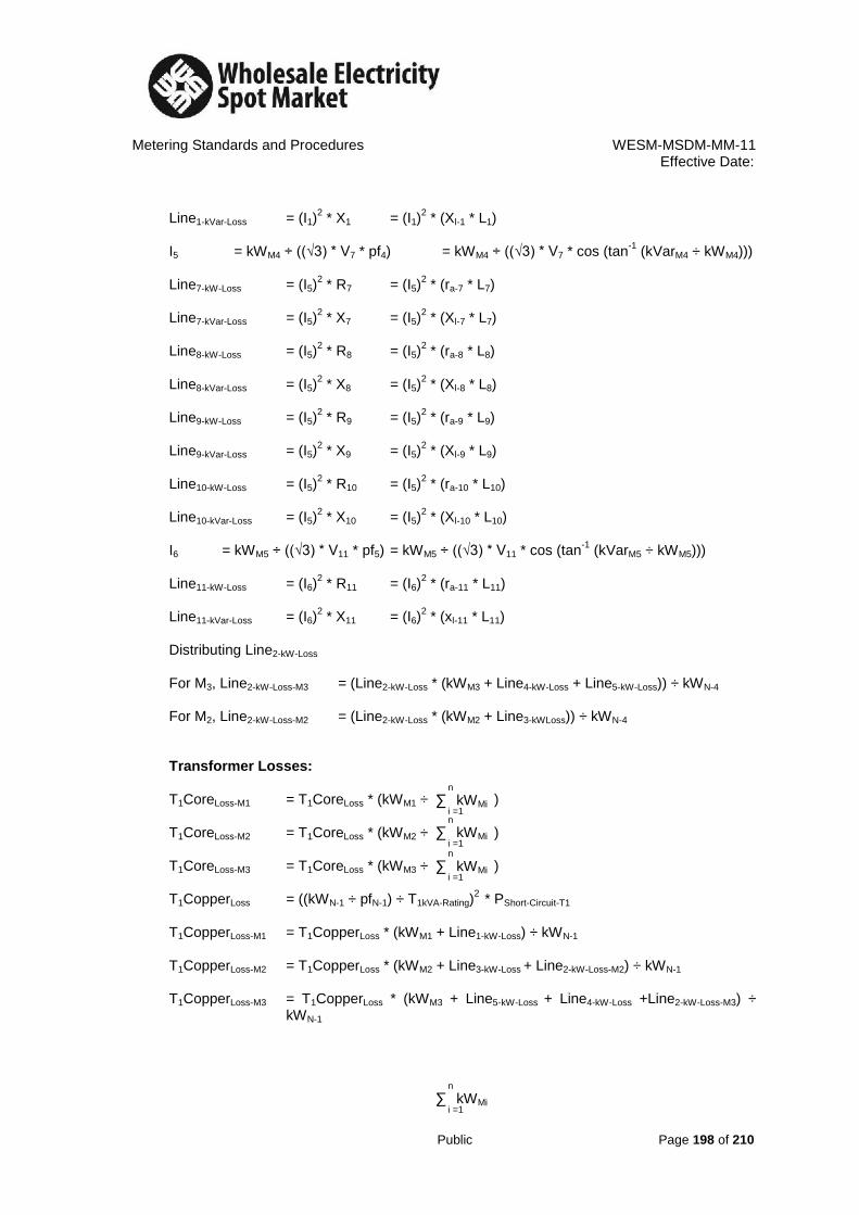
Metering Standards and Procedures WESM-MSDM-MM-11 Effective Date:
Public Page 198 of 210
Line1-kVar-Loss = (I1)
2 * X1 = (I1)
2 * (Xl-1 * L1)
I5 = kWM4 ÷ ((√3) * V7 * pf4) = kWM4 ÷ ((√3) * V7 * cos (tan
-1 (kVarM4 ÷ kWM4)))
Line7-kW-Loss = (I5)
2 * R7 = (I5)
2 * (ra-7 * L7)
Line7-kVar-Loss = (I5)
2 * X7 = (I5)
2 * (Xl-7 * L7)
Line8-kW-Loss = (I5)
2 * R8 = (I5)
2 * (ra-8 * L8)
Line8-kVar-Loss = (I5)
2 * X8 = (I5)
2 * (Xl-8 * L8)
Line9-kW-Loss = (I5)
2 * R9 = (I5)
2 * (ra-9 * L9)
Line9-kVar-Loss = (I5)
2 * X9 = (I5)
2 * (Xl-9 * L9)
Line10-kW-Loss = (I5)
2 * R10 = (I5)
2 * (ra-10 * L10)
Line10-kVar-Loss = (I5)
2 * X10 = (I5)
2 * (Xl-10 * L10)
I6 = kWM5 ÷ ((√3) * V11 * pf5) = kWM5 ÷ ((√3) * V11 * cos (tan
-1 (kVarM5 ÷ kWM5)))
Line11-kW-Loss = (I6)
2 * R11 = (I6)
2 * (ra-11 * L11)
Line11-kVar-Loss = (I6)
2 * X11 = (I6)
2 * (xl-11 * L11)
Distributing Line2-kW-Loss For M3, Line2-kW-Loss-M3 = (Line2-kW-Loss * (kWM3 + Line4-kW-Loss + Line5-kW-Loss)) ÷ kWN-4 For M2, Line2-kW-Loss-M2 = (Line2-kW-Loss * (kWM2 + Line3-kWLoss)) ÷ kWN-4 Transformer Losses: T1CoreLoss-M1 = T1CoreLoss * (kWM1 ÷ )
T1CoreLoss-M2 = T1CoreLoss * (kWM2 ÷ ) T1CoreLoss-M3 = T1CoreLoss * (kWM3 ÷ ) T1CopperLoss = ((kWN-1 ÷ pfN-1) ÷ T1kVA-Rating)
2 * PShort-Circuit-T1
T1CopperLoss-M1 = T1CopperLoss * (kWM1 + Line1-kW-Loss) ÷ kWN-1 T1CopperLoss-M2 = T1CopperLoss * (kWM2 + Line3-kW-Loss + Line2-kW-Loss-M2) ÷ kWN-1 T1CopperLoss-M3 = T1CopperLoss * (kWM3 + Line5-kW-Loss + Line4-kW-Loss +Line2-kW-Loss-M3) ÷
kWN-1
n
∑
kWMi
i =1 n
∑
kWMi
i =1
n
∑
kWMi
i =1
n
∑
kWMi
i =1
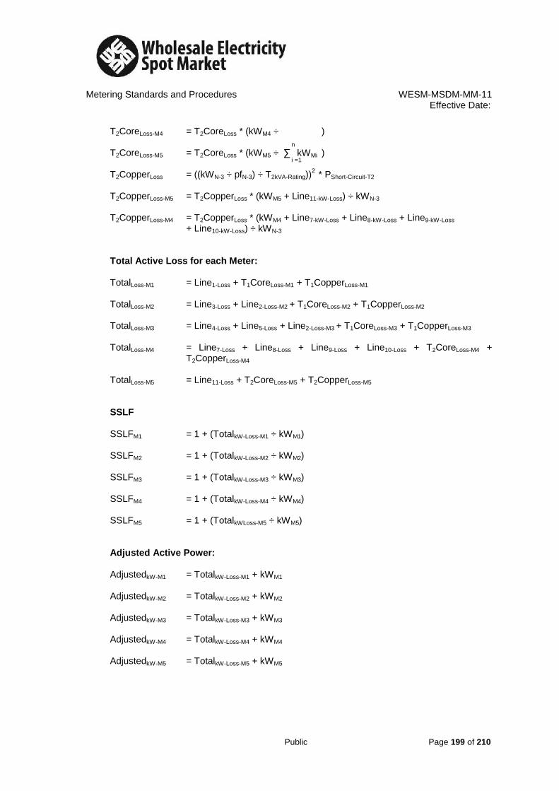
Metering Standards and Procedures WESM-MSDM-MM-11 Effective Date:
Public Page 199 of 210
T2CoreLoss-M4 = T2CoreLoss * (kWM4 ÷ )
T2CoreLoss-M5 = T2CoreLoss * (kWM5 ÷ ) T2CopperLoss = ((kWN-3 ÷ pfN-3) ÷ T2kVA-Rating))
2 * PShort-Circuit-T2
T2CopperLoss-M5 = T2CopperLoss * (kWM5 + Line11-kW-Loss) ÷ kWN-3 T2CopperLoss-M4 = T2CopperLoss * (kWM4 + Line7-kW-Loss + Line8-kW-Loss + Line9-kW-Loss + Line10-kW-Loss) ÷ kWN-3 Total Active Loss for each Meter: TotalLoss-M1 = Line1-Loss + T1CoreLoss-M1 + T1CopperLoss-M1 TotalLoss-M2 = Line3-Loss + Line2-Loss-M2 + T1CoreLoss-M2 + T1CopperLoss-M2 TotalLoss-M3 = Line4-Loss + Line5-Loss + Line2-Loss-M3 + T1CoreLoss-M3 + T1CopperLoss-M3 TotalLoss-M4 = Line7-Loss + Line8-Loss + Line9-Loss + Line10-Loss + T2CoreLoss-M4 +
T2CopperLoss-M4
TotalLoss-M5 = Line11-Loss + T2CoreLoss-M5 + T2CopperLoss-M5 SSLF SSLFM1 = 1 + (TotalkW-Loss-M1 ÷ kWM1) SSLFM2 = 1 + (TotalkW-Loss-M2 ÷ kWM2)
SSLFM3 = 1 + (TotalkW-Loss-M3 ÷ kWM3)
SSLFM4 = 1 + (TotalkW-Loss-M4 ÷ kWM4) SSLFM5 = 1 + (TotalkWLoss-M5 ÷ kWM5) Adjusted Active Power: AdjustedkW-M1 = TotalkW-Loss-M1 + kWM1 AdjustedkW-M2 = TotalkW-Loss-M2 + kWM2 AdjustedkW-M3 = TotalkW-Loss-M3 + kWM3 AdjustedkW-M4 = TotalkW-Loss-M4 + kWM4 AdjustedkW-M5 = TotalkW-Loss-M5 + kWM5
n
∑
kWMi
i =1

Metering Standards and Procedures WESM-MSDM-MM-11 Effective Date:
Public Page 200 of 210
Case 4: Lagging MTN: A metering point is located before the MTN. The meter is installed at a voltage level higher or equal to the voltage level of the MTN (figure 10).
Figure 10
L3 L1
M
1 I1
M
2
I2
I4
Market Trading Node
M
3 I3
Transformer Loss
L2
L4

Metering Standards and Procedures WESM-MSDM-MM-11 Effective Date:
Public Page 201 of 210
Simplifying Figure 10:
Figure 11
Active and Reactive Power: kWM1 = (kWhM1-15min + kWhM1-30min + kWhM1-45min + kWhM1-00min) ÷ 1h kVarM1 = (kVarhM1-15min + kVarhM1-30min + kVarhM1-45min + kVarhM1-00min) ÷ 1h kWM2 = (kWhM2-15min + kWhM2-30min + kWhM2-45min + kWhM2-00min) ÷ 1h kVarM2 = (kVarhM2-15min + kVarhM2-30min + kVarhM2-45min + kVarhM2-00min) ÷ 1h kWM3 = (kWhM3-15min + kWhM3-30min + kWhM3-45min + kWhM3-00min) ÷ 1h kVarM3 = (kVarhM3-15min + kVarhM3-30min + kVarhM3-45min + kVarhM3-00min) ÷ 1h Line Currents and Line Losses: I1 = kWM1 ÷ ((√3) * V1 * pf1) = kWM1 ÷ ((√3) * V1 * cos (tan
-1 (kVarM1 ÷ kWM1)))
I2 = kWM2 ÷ ((√3) * V2 * pf2) = kWM2 ÷ ((√3) * V2 * cos (tan
-1 (kVarM2 ÷ kWM2)))
I3 = kWM3 ÷ ((√3) * V3 * pf3) = kWM3 ÷ ((√3) * V3 * cos (tan
-1 (kVarM3 ÷ kWM3)))
L3 L1
M
1 I1
M
2
I2
Market Trading Node
M
3 I3
Transformer Loss
L2
L4

Metering Standards and Procedures WESM-MSDM-MM-11 Effective Date:
Public Page 202 of 210
Line1-kW-Loss = (I1)2 * R1 = (I1)
2 * (ra-1 * L1)
Line1-kVar-Loss = (I1)
2 * X1 = (I1)
2 * (Xl-1 * L1)
Line2-kW-Loss = (I2)
2 * R2 = (I2)
2 * (ra-2 * L2)
Line2-kVar-Loss = (I2)
2 * X2 = (I2)
2 * (Xl-2 * L2)
Line3-kW-Loss = (I3)
2 * R3 = (I3)
2 * (ra-3 * L3)
Line3-kVar-Loss = (I3)
2 * X3 = (I3)
2 * (Xl-3 * L3)
Total Active Power at Node 1 (kWN-1) = kWM1 + kWM2 + kWM3 + Line1-kW-Loss + Line2-kW-Loss + Line3-kW-Loss
Total Reactive Power at Node 1 (kVarN-1) = kVarM1 + kVarM2 + kVarM3 + Line1-kVar-Loss + Line2-kVar-Loss + Line3-kVar-Loss
I4 = kWN-1 ÷ ((√3) * VN-1 * pfN-1) = kWN-1 ÷ ((√3) * VN-1 * cos (tan
-1 (kVarN-1 ÷ kWN-1)))
Line4-kW-Loss = (I4)
2 * R4 = (I4)
2 * (ra-4 * L4)
Line4-kVar-Loss = (I4)
2 * X4 = (I4)
2 * (xl-4 * L4)
Distributing Line4-kW-Loss For M1, Line4-kW-Loss-M1 = (Line4-kW-Loss * (kWM1 + Line1-kW-Loss)) ÷ kWN-1 For M2, Line4-kW-Loss-M2 = (Line4-kW-Loss * (kWM2 + Line2-kW-Loss)) ÷ kWN-1 For M3, Line4-kW-Loss-M3 = (Line4-kW-Loss * (kWM3 + Line3-kW-Loss)) ÷ kWN-1 Transformer Losses: T1CoreLoss-M1 = T1CoreLoss * (kWM1 ÷ )
T1CoreLoss-M2 = T1CoreLoss * (kWM2 ÷ ) T1CoreLoss-M3 = T1CoreLoss * (kWM3 ÷ ) T1CopperLoss = ((kWN-1 ÷ pfN-1) ÷ T1kVA-Rating)
2 * PShort-Circuit-T1
T1CopperLoss-M1 = T1CopperLoss * (kWM1 + Line1-kW-Loss + Line4-kW-Loss-M1) ÷ kWN-1 T1CopperLoss-M2 = T1CopperLoss * (kWM2 + Line2-kW-Loss + Line4-kW-Loss-M2) ÷ kWN-1 T1CopperLoss-M3 = T1CopperLoss * (kWM3 + Line3-kW-Loss + Line4-kW-Loss-M3‘) ÷ kWN-1 Total Loss for each Meter: TotalkW-Loss-M1 = Line1-kW-Loss + Line4-kWLoss-M1 + T1CoreLoss-M1 + T1CopperLoss-M1 TotalkW-Loss-M2 = Line2-kW-Loss + Line4-kWLoss-M2 + T1CoreLoss-M2 + T1CopperLoss-M2
n
∑
kWMi
i =1
n
∑
kWMi
i =1
n
∑
kWMi
i =1

Metering Standards and Procedures WESM-MSDM-MM-11 Effective Date:
Public Page 203 of 210
TotalkW-Loss-M3 = Line3-kW-Loss + Line4-kW-Loss-M3 + T1CoreLoss-M3 + T1CopperLoss-M3 SSLF
SSLFM1 = 1 - (TotalkW-Loss-M1 ÷ kWM1) SSLFM2 = 1 - (TotalkW-Loss-M2 ÷ kWM2) SSLFM3 = 1 - (TotalkW-Loss-M3 ÷ kWM3)
Adjusted Meter Data: AdjustedkW-M1 = kWM1 - TotalkW-Loss-M1 AdjustedkW-M2 = kWM2 - TotalkW-Loss-M2 AdjustedKW-M3 = kWM3 - TotalkW-Loss-M3

Metering Standards and Procedures WESM-MSDM-MM-11 Effective Date:
Public Page 204 of 210
Generators
Case 1: One Metering Point – One Market Trading Node: A metering point measures the dispatch of only one generating unit (figure 12).
Figure 12 kWMi = (kWhMi-15min + kWhMi-30min + kWhMi-45min + kWhMi-00min) ÷ 1h kVarMi = (kVarhMi-15min + kVarhMi-30min + kVarhMi-45min + kVarhMi-00min) ÷ 1h
ILine = kWMi ÷ ((√3) * V * pfMi), pfMi = cos (tan
-1 (kVarMi ÷ kWMi))
LinekW-Loss = (ILine)
2 * RLine, RLine = ra * L
LinekVar-Loss = (ILine)
2 * XLine, XLine = xl * L
CoreLoss-Mi = T1CoreLoss ÷ 1
CopperLoss-Mi = ((kWMi ÷ pfMi) ÷ TkVA-Rating) 2
* PShort-Circuit TotalkW-Loss = LinekW-Loss + CoreLoss-Mi + CopperLoss-Mi
SSLF = 1 + (TotalkW-Loss ÷ kWMi) AdjustedkW = SSLF * kWMi = TotalkW-Loss + kWMi
L
Market Trading Node
Transformer Loss
Mi
ILine
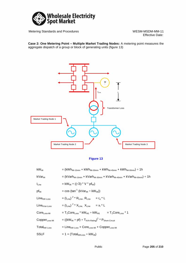
Metering Standards and Procedures WESM-MSDM-MM-11 Effective Date:
Public Page 205 of 210
Case 2: One Metering Point – Multiple Market Trading Nodes: A metering point measures the aggregate dispatch of a group or block of generating units (figure 13)
Figure 13
kWMi = (kWhMi-15min + kWhMi-30min + kWhMi-45min + kWhMi-00min) ÷ 1h kVarMi = (kVarhMi-15min + kVarhMi-30min + kVarhMi-45min + kVarhMi-00min) ÷ 1h ILine = kWMi ÷ ((√3) * V * pfMi) pfMi = cos (tan
-1 (kVarMi ÷ kWMi))
LinekW-Loss = (ILine)
2 * RLine, RLine = ra * L
LinekVar-Loss = (ILine)
2 * XLine, XLine = xl * L
CoreLoss-Mi = T1CoreLoss * kWM1 ÷ kWM1 = T1CoreLoss * 1 CopperLoss-Mi = ((kWMi ÷ pf) ÷ TkVA-Rating)
2 * PShort-Circuit
TotalkW-Loss = LinekW-Loss + CoreLoss-Mi + CopperLoss-Mi SSLF = 1 + (TotalkWLoss ÷ kWMi)
L
Transformer Loss
Mi
ILine
Market Trading Node 3
Market Trading Node 1
Market Trading Node 2

Metering Standards and Procedures WESM-MSDM-MM-11 Effective Date:
Public Page 206 of 210
AdjustedkW = TotalkWLoss + kWMi = SSLF * kWMi Disaggregation of Adjusted Active Power: MTN1-Meter-Equivalent = AdjustedkW * (EPQMTN1 ÷ )
MTN2-Meter-Equivalent = AdjustedkW * (EPQMTN2 ÷ )
MTN3-Meter-Equivalent = AdjustedkW * (EPQMTN3 ÷ )
Where: EPQMTN = Real Time Ex-Post Quantity of the generator
Case 3: Multiple Metering Points – Multiple Market Trading Nodes: A group of metering points measures the aggregate dispatch of a group or block of generating units (figure 14).
Figure 14
I4 L L
L
L2
L1
M
1 I1
M
2
I2 I3
Market Trading Node 1
Transformer 1 Loss
Market Trading Node 2
Transformer 2 Loss
n
∑
EPQMTNi
i =1
n
∑
EPQMTNi
i =1
n
∑
EPQMTNi
i =1

Metering Standards and Procedures WESM-MSDM-MM-11 Effective Date:
Public Page 207 of 210
Simplifying Figure 14:
Figure 15 Active and Reactive Power: kWM1 = (kWhM1-15min + kWhM1-30min + kWhM1-45min + kWhM1-00min) ÷ 1h kVarM1 = (kVarhM1-15min + kVarhM1-30min + kVarhM1-45min + kVarhM1-00min) ÷ 1h kWM2 = (kWhM2-15min + kWhM2-30min + kWhM2-45min + kWhM2-00min) ÷ 1h kVarM2 = (kVarhM2-15min + kVarhM2-30min + kVarhM2-45min + kVarhM2-00min) ÷ 1h Line Currents and Line Losses: I1 = kWM1 ÷ ((√3) * V1 * pf1) = kWM1 ÷ ((√3) * V1 * cos (tan
-1 (kVarM1 ÷ kWM1)))
I2 = kWM2 ÷ ((√3) * V2 * pf2) = kWM2 ÷ ((√3) * V2 * cos (tan
-1 (kVarM2 ÷ kWM2)))
Line1-kWLoss = (I1)
2 * R1 = (I1)
2 * (ra-1 * L1)
Line1-kVarLoss = (I1)
2 * X1 = (I1)
2 * (Xl-1 * L1)
Transformer 1
L2
M
1 I1
M
2
I2 I3
Node 1
Market Trading Node 2
Transformer 2
I4
L3
L4
L4
L1
Market Trading Node 1

Metering Standards and Procedures WESM-MSDM-MM-11 Effective Date:
Public Page 208 of 210
Line2-kWLoss = (I2)
2 * R2 = (I2)
2 * (ra-2 * L2)
Line2-kVarLoss = (I2)
2 * X2 = (I2)
2 * (Xl-2 * L2)
Total Active Power at Node 1 (kWN-1) = kWM1 + kWM2 + Line1-kW-Loss + Line2-kW-Loss Total Reactive Power at Node 1 (kVarN-1) = kVarM1 + kVarM2 + Line1-kVar-Loss + Line2-kVar-Loss I1 + I2 = I3 + I4 Since current (I) is inversely proportional to resistance (R), I = 1 ÷ R I3 = (I1 + I2) * R4 ÷ (R3 + R4), I4 = (I1 + I2) * R3 ÷ (R3 + R4) Line3-kW-Loss = (I3)
2 * R3 = (I3)
2 * (ra-3 * L3)
Line3-kVar-Loss = (I3)
2 * X3 = (I3)
2 * (Xl-3 * L3)
Line4-kW-Loss = (I4)
2 * R4 = (I4)
2 * (ra-4 * L4)
Line4-kVar-Loss = (I4)
2 * X4 = (I4)
2 * (Xl-4 * L4)
Distributing Line3-kW-Loss For M1, Line3-kW-Loss-M1 = (Line3-kW-Loss * (kWM1 + Line1-kW-Loss)) ÷ kWN-1 For M2, Line3-kW-Loss-M2 = (Line3-kW-Loss * (kWM2 + Line2-kW-Loss)) ÷ kWN-1 Distributing Line4-kW-Loss For M1, Line4-kW-Loss-M1 = (Line4-kW-Loss * (kWM1 + Line1-kW-Loss)) ÷ kWN-1 For M2, Line4-kW-Loss-M2 = (Line4-kW-Loss * (kWM2 + Line2-kW-Loss)) ÷ kWN-1 Transformer Losses: T1CoreLoss-M1 = T1CoreLoss * (kWM1 ÷ )
T1CoreLoss-M2 = T1CoreLoss * (kWM2 ÷ ) T2CoreLoss-M1 = T2CoreLoss * (kWM1 ÷ )
T2CoreLoss-M2 = T2CoreLoss * (kWM2 ÷ ) T1CopperLoss = (((kWN-1 ÷ 2) ÷ pfN-1) ÷ T1kVA-Rating))
2 * PShort-Circuit-T1
T1CopperLoss-M1 = T1CopperLoss * (kWM1 + Line1-kW-Loss) ÷ kWN-1 T1CopperLoss-M2 = T1CopperLoss * (kWM2 + Line2-kW-Loss) ÷ kWN-1 T2CopperLoss = (((kWN-1 ÷ 2) ÷ pfN-1) ÷ T2kVA-Rating))
2 * PShort-Circuit-T2
n
∑
kWMi
i =1
n
∑
kWMi
i =1
n
∑
kWMi
i =1
n
∑
kWMi
i =1

Metering Standards and Procedures WESM-MSDM-MM-11 Effective Date:
Public Page 209 of 210
T2CopperLoss-M1 = T2CopperLoss * (kWM1 + Line1-kW-Loss) ÷ kWN-1 T2CopperLoss-M2 = T2CopperLoss * (kWM2 + Line2-kW-Loss) ÷ kWN-1 T1CopperLoss-M1 = ((kWM1 ÷ pf1) ÷ T1kVA-Rating)
2 * PShort-Circuit-T1
Total Loss for each Meter: TotalkW-Loss-M1 = Line1-kW-Loss + Line3-kW-Loss-M1 + Line4-kW-Loss-M1 + T1CoreLoss-M1 +
T2CoreLoss-M1 + T1CopperLoss-M1 + T2CopperLoss-M1 TotalkW-Loss-M2 = Line2-kW-Loss + Line3-kW-Loss-M2 + Line4-kW-Loss-M2 + T1CoreLoss-M2 +
T2CoreLoss-M2 + T1CopperLoss-M2 + T2CopperLoss-M2 SSLF
SSLFM1 = 1 + (TotalkW-Loss-M1 ÷ kWM1) SSLFM2 = 1 + (TotalkW-Loss-M2 ÷ kWM2) SSLFM3 = 1 + (TotalkW-Loss-M3 ÷ kWM3) SSLFM4 = 1 + (TotalkW-Loss-M4 ÷ kWM4)
Adjusted Active Power: AdjustedkW-M1 = TotalkW-Loss-M1 + kWM1 AdjustedkW-M2 = TotalkW-Loss-M2 + kWM2 Disaggregation of Adjusted Meter Data: MTN1-Meter-Equivalent = AdjustedkW- M1 * EPQMTN1 ÷
+ AdjustedkW-M2 * EPQMTN1 ÷
= AdjustedkW- M1 + AdjustedkW-M2 * (EPQMTN1 ÷ ) MTN2-Meter-Equivalent = AdjustedkW-M1 * EPQMTN2 ÷
+ AdjustedkW-M2 * EPQMTN2 ÷
= AdjustedkW- M1 + AdjustedkW-M2 * (EPQMTN2 ÷ )
n
∑
EPQMTNi
i =1
n
∑
EPQMTNi
i =1
n
∑
EPQMTNi
i =1
n
∑
EPQMTNi
i =1
n
∑
EPQMTNi
i =1 n
∑
EPQMTNi
i =1

Metering Standards and Procedures WESM-MSDM-MM-11 Effective Date:
Public Page 210 of 210
REFERENCES
a. Electric Power Industry Reform Act (EPIRA -RA 9136)
b. WESM Rules
c. Philippine Grid Code
d. Philippine Distribution Code
e. Open Access Transmission Service (OATS)
f. Philippine Electrical Code (PEC) Part 1
g. Philippine Electrical Code (PEC) Part 2
h. International Electro technical Commission (IEC)
i. American National Standard Institute (ANSI)
j. Institute of Electrical and Electronics Engineer (IEEE)
k. Handbook for Electricity Metering
l. TRANSCO Maintenance Manual