Meteorology - VATSIM Scandinavia de-coding v11.pdf · 6 3.1.1 Wind Wind is measured 10 m above...
12
1 Meteorology METAR de-coding Made by: Sebastian Rekdal | Chief of Training Norway Updated: 2015-01-21 | January 21, 2014
Transcript of Meteorology - VATSIM Scandinavia de-coding v11.pdf · 6 3.1.1 Wind Wind is measured 10 m above...
1
Meteorology METAR de-coding
Made by: Sebastian Rekdal | Chief of Training Norway
Updated: 2015-01-21 | January 21, 2014

2
Table of Content
1. General ................................................................................................................................................................ 3
1.1 Purpose ............................................................................................................................................................. 3
1.2 Credits .............................................................................................................................................................. 3
1.3 Feedback and contact information .................................................................................................................... 3
2. Introduction ........................................................................................................................................................ 4
2.1 Meteorology introduction ................................................................................................................................... 4
3. METAR de-coding ............................................................................................................................................... 4
3.1 METAR - Aviation Routine Weather Report ....................................................................................................... 4
3.1.1 Wind ................................................................................................................................................. 6
3.1.2 Visibility ............................................................................................................................................. 6
3.1.3 Runway Visual Range (RVR) ........................................................................................................... 6
3.1.4 Weather Phenomena ........................................................................................................................ 7
3.1.5 Clouds .............................................................................................................................................. 7
3.1.6 CAVOK ............................................................................................................................................. 7
3.1.7 Temperature and dew point .............................................................................................................. 8
3.1.8 Air pressure - QNH ........................................................................................................................... 8
3.1.9 Trend ................................................................................................................................................ 8
3.1.10 Runway Conditions ......................................................................................................................... 9
3.2. VMC - Visual Meteorological Conditions ......................................................................................................... 10
3.2.1 VMC Minimums .............................................................................................................................. 10
3.3 Figure METAR Reference ................................................................................................................................ 11
3
Chapter 1. General 1.1 Purpose The main purpose of the ATC Training Manual Norway FIR is to provide standardized local and general
procedures for controller in Norway FIR. This document is made in respect of all air traffic controllers who needs
help to understand meteorology. This document provides standardized meteorology (METAR and de-coding of
METAR) within Europe (source: EuroControl).
We hope that this document can help you improve your aviation knowledge. Our goal is to make you understand
the basics behind a controller unit who is controlling within Europe (more specific: Norway FIR).
On behalf of the crew in VATSIM Scandinavia and the creator of this document, Sebastian Rekdal (Chief of
Training Norway), we wish you good luck with your air traffic control (ATC) training on VATSIM, and welcome to
VATSIM Scandinavia!
1.2 Credits The ATC Training Manual Norway FIR was created by VATSIM Scandinavia. Original appendices published
October 10, 2014 was made by Sebastian Rekdal (Chief of Training Norway). Thanks to:
Sebastian Rekdal | Chief of Training Norway ([email protected])
1.3 Feedback and contact information If you have any questions, comments, suggestions or complains regarding this manual, please do not hesitate to
contact us. Please let us know about your concern…
Chief of Training Norway (Sebastian Rekdal): [email protected]
Director of Norway FIR (Daniel Klepp): [email protected]
Discussion forum (need forum-account): http://www.forum.vatsim-scandinavia.org/
If you find any errors, outdated procedures or typos in this manual, please do not hesitate to E-mail us:
[email protected]. Help us keep the documents clean, realistic and updated!

4
Chapter 2. Introduction 2.1 Meteorology Introduction
Weather knowledge is essential in aviation: Visibility, air pressure, thunderstorms, temperature, clouds, rain and
dew point etc.
All affect flying in one way or another. You are most affected by weather when flying VFR, but also when flying
IFR, there are restrictions how bad weather can be before plans must be changed. In this section, we'll look into
how weather is reported, but not how weather affects flight.
There are many acronyms and concepts in weather reporting, which we will learn throughout the rest of this
document. Below we'll cover rather completely the weather report. There are many acronyms and concepts. You
need not know them all from the beginning, but you must be able to get the name of the airport, wind and air
pressure. Since you as a controller read the weather report to the pilots, you'll soon learn the rest of the
acronyms.
Chapter 3. METAR de-coding 3.1 METAR – Aviation Routine Weather Report
*As a Student you should have knowledge about what a METAR is and recognize the most essential parts (Where, when,
winds and QNH) by heart and know where to find information about the other elements. As a Senior Student you should be
able to read out a whole METAR.
At major airports, weather observations are made every half hour, day and night.
The weather in the METAR is the weather observed 10 minutes before the report.
The following is part of a METAR:
Airport (for example ENGM for Oslo airport Gardermoen)
Observation time (day of the month and time followed by Z)
Wind at ground level: direction, speed and unit (knots)
Meteorological visibility (in meters)
Runway Visual Range (RVR) if visibility is below 1500 m.
Present weather
Clouds, amount, type and base
Air temperature and dew point
QNH (air pressure), preceded by Q.
Other information, for example wind change.
Landing forecast, trend.
The following is a brief breakdown of some of the basic METAR elements:
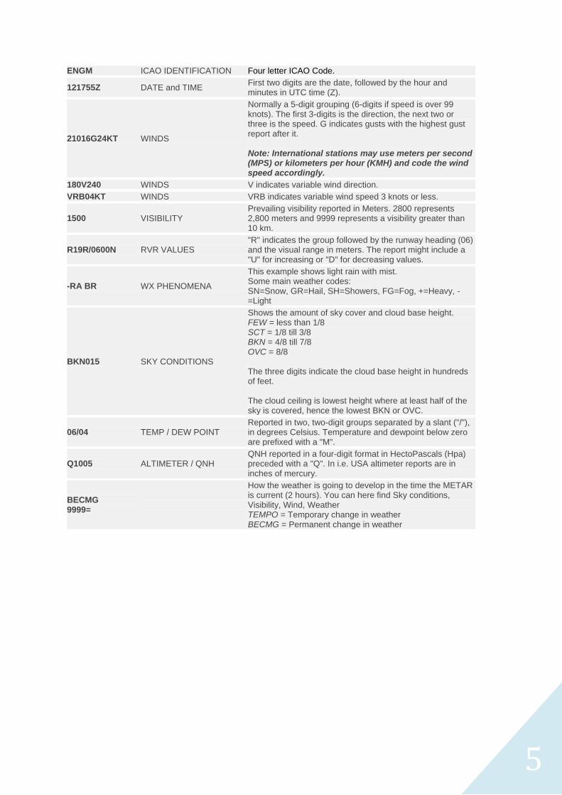
METAR ENGM 121755Z 21016G24KT 180V240 1500 R19R/0600N +RA BR BKN015 0VC025 06/04 Q1005 BECMG 9999=
5
ENGM ICAO IDENTIFICATION Four letter ICAO Code.
121755Z DATE and TIME First two digits are the date, followed by the hour and minutes in UTC time (Z).
21016G24KT WINDS
Normally a 5-digit grouping (6-digits if speed is over 99 knots). The first 3-digits is the direction, the next two or three is the speed. G indicates gusts with the highest gust report after it. Note: International stations may use meters per second (MPS) or kilometers per hour (KMH) and code the wind speed accordingly.
180V240 WINDS V indicates variable wind direction.
VRB04KT WINDS VRB indicates variable wind speed 3 knots or less.
1500 VISIBILITY Prevailing visibility reported in Meters. 2800 represents 2,800 meters and 9999 represents a visibility greater than 10 km.
R19R/0600N RVR VALUES "R" indicates the group followed by the runway heading (06) and the visual range in meters. The report might include a "U" for increasing or "D" for decreasing values.
-RA BR WX PHENOMENA
This example shows light rain with mist. Some main weather codes: SN=Snow, GR=Hail, SH=Showers, FG=Fog, +=Heavy, -=Light
BKN015 SKY CONDITIONS
Shows the amount of sky cover and cloud base height. FEW = less than 1/8 SCT = 1/8 till 3/8 BKN = 4/8 till 7/8 OVC = 8/8 The three digits indicate the cloud base height in hundreds of feet. The cloud ceiling is lowest height where at least half of the sky is covered, hence the lowest BKN or OVC.
06/04 TEMP / DEW POINT Reported in two, two-digit groups separated by a slant ("/"), in degrees Celsius. Temperature and dewpoint below zero are prefixed with a "M".
Q1005 ALTIMETER / QNH QNH reported in a four-digit format in HectoPascals (Hpa) preceded with a "Q". In i.e. USA altimeter reports are in inches of mercury.
BECMG 9999=
How the weather is going to develop in the time the METAR is current (2 hours). You can here find Sky conditions, Visibility, Wind, Weather TEMPO = Temporary change in weather BECMG = Permanent change in weather

6
3.1.1 Wind
Wind is measured 10 m above ground.
The direction is from where the wind is coming. The precision is 10 degrees. In the METAR, the wind velocity is a
10 minute average and given in knots (kt). If there are gusts 10 KT over the average value, this is reported as
well. The gusts are reported as G17 and should be read “gusting” or “maximum”.
When flying, the wind direction in itself isn't the most important factor, but it’s the side-wind component. If the wind
direction varies more than 60 degrees and if there's more than 3 kt wind, it is reported as V (variable). If there is
less than 3 knots wind and it varies, this is reported as VRB. Calm is reported as 00000KT.
Example:
VRB02KT – variable two knots
25020KT – two five zero degrees two zero knots
15015G25KT – one five zero degrees one five knots maximum (or gusting) two five knots
24018G35KT 160V290 – two four zero degrees one eight knots maximum (or gusting) three five knots
variable between one six zero and two niner zero degrees
3.1.2 Visibility
Visibility is often of vital importance. There are three ways of obtaining the visibility:
Flight Visibility is the visibility forward from the cockpit of an aircraft in flight.
The Ground Visibility, which is given in the ATIS and METAR, is the visibility at an aerodrome, as
reported by an accredited observer.
Ground visibility reading, which is measured automatically.
The two latter is the distance measured to a large unlit object, where the contours of this object can be seen.
Visibility is affected by moisture, ice crystals, salt or dust in the air.
Visibility in darkness is today most often measured with infrared light.
Visibility is measured in steps up to 10 km.
Visibility below 50 m is written as 0000 and 10 km or more as 9999.
Visibility below 5000 m is given in m, and above in km.
Example:
450 – visibility four five zero meters
1500 – visibility one five zero zero (or one thousand five hundred) meters
9999 – visibility more then ten kilometers
Special case: 1800N 7000S – visibility to north one eight zero zero meters, to south seven kilometres.
3.1.3 Runway Visual Range (RVR)
Runway visual range is only given if the visibility and/or the RVR (Runway Visibility Range) is less than 1500
meters. The RVR is prefixed by the letter R followed by runway designator, then a slash (/) followed by the RVR in
meters. The lowest value for RVR that may be stated is 50 meters, or the lowest limit for the system, if RVR is
lower than that, the letter M will be used after the slash, as in this example: R36/M0050, meaning that for RWY36
the RVR is less than 50 meters.
If the RVR is more than 1500 meters, or more than the upper limit for the system used for measuring, the letter P will be used to prefix the RVR value. (Example R19/P2000, R19/P1500
If the RVR is measured by instruments, it is usually the mean RVR over ten minutes that is given. If the RVR varies during these 10 minutes, this is indicated by giving minimum and maximum values, separated by an indicator:
Example: R36/0300V750D: Runway 36 has an RVR of minimum 300 meters, maximum 750 meters, but the RVR is going down (D).

7
If the RVR has a tendency either up or down, or no tendency, this is notified by the use of the letters U (up), D (down) or N (no change).
Example: R01/0900U: Mean RVR of 900 meters and the RVR is improving.
Other RVR codes:
M: visibility is below what can be measured, or below 50m
P: RVR is more than 1500 m
V: RVR varies
U: RVR is going Up
D: RVR is going Down
Examples:
R29L/0700 – R-V-R two niner left seven zero zero meters
R19R/M0150D – R-V-R one niner right below one five zero meters going down
R26/0350V0600U – R-V-R two six variable between three five zero and six zero zero meters going up
3.1.4 Weather Phenomena
Current weather is included in the METAR. It is abbreviated with two letters. If this isn't enough, the abbreviations
can be combined. The abbreviations are listed at the end of this chapter. Some abbreviations can be preceded
with a ”+” (plus) or ”-” (minus), this lists the intensity. VC means Vicinity, which means within 8 km from the airport.
Exception: thunder and cumulonimbus clouds. Sometimes the recent weather is also reported, in this case ”RE”
precedes the weather condition.
Examples:
SN BLSN – Snow and blowing snow
+FZDZ FG – Heavy freezing drizzle with fog
RESN – Recent snow
3.1.5 Clouds
There are a number of reported clouds types, but only two are important to differentiate: Cumulonimbus (CB) and
Towering Cumulus (TCU). Otherwise, only the fraction of sky covered by clouds is measured. This was previously
reported in 1/8's, but nowadays this is described in words:
0/8: Sky clear (SKC)
1-2/8: Few (FEW)
3-4/8: Scattered (SCT)
5-7/8: Broken (BKN)
8/8: Overcast (OVC)
The cloud base above the airport's reference height AGL (Above Ground Level) is measured in hundreds of feet.
001 means 100 ft, 012 = 1200 ft and 120 = 12000 ft. Vertical visibility is reported as VV, and if this is not
measured VV///.
Examples:
BKN002 – Broken two hundred feet
SCT013 BKN120 – Scattered one thousand three hundred feet broken one two thousand feet.
SCT035TCU – Scattered three thousand five hundred feet, towering cumulus.

8
3.1.6 CAVOK
CAVOK, or Ceiling and visibility OK, replaces visibility, weather and clouds if: visibility ≥10km; no cloud below
5000 ft (1500m) or below the highest minimum sector altitude, whichever is greater and no CB or TCU
(Cumulonimbus); and no precipitation, TS, DS, SS, MIFG, DRDU, DRSA, or DRSN.
The full readout of CAVOK is “Ceiling and Visibility OK”. The most common is the latter, but the most correct
ought to be the first. This is because ‘ceiling’ means BKN or OVC when it comes to clouds and the definition of
CAVOK is that NO clouds should be present below 5000ft.
3.1.7 Temperature and dew point
The air temperature is measured in degrees Celsius. If below 0, it is preceded by an M. The dew point is defined
as the temperature the air must be cooled to, to get saturation, i.e. relative humidity 100%. If below 0, it is
preceded by an M.
Dew point is important to the pilot since this value gives information about visibility, clouds and together with the
temperature indicates the risk of ice-formation. The closer the temperature and dew point are, the more humidity
is in the air and the worse is the visibility.
The difference between temperature and dew point is called spread. If you calculate SPREAD x 400ft you will get
the lowest cloud base.
Example:
02/M04 – Temperature two dew point minus four
3.1.8 Air Pressure - QNH
As described in other sections in this manual, the air pressure is vital to know, since it affects the altitude
measuring system. Air pressure can be measured in different ways, and relative different levels. QNH is air
pressure at sea level (or reduced to sea level in standard atmosphere if it’s measured at another point).
QFE is air pressure at the airport. A high value means high air pressure and vice versa. Standard pressure is
1013.25 hPa or 29.92 inch Hg.
In the METAR, the value is preceded by a Q if the unit is hPa and A if it's inch Hg. Q is used in Europe.
Example:
Q0987 – Q-N-H niner eight seven
3.1.9 Trend
The trend prognosis should indicate expected changes within next two hours.
There are three MAIN concepts used in Trend:
Becoming (BECMG)
Temporary (TEMPO)
No Significant Change (stable) (NOSIG)
The first two can be given with a time reference.
Examples:
BECMG FM1250 TL1340 – Becoming from 1250 till 1340 (the change will take place between 12:50 to
13:40)
BECMG AT 1400 – Becoming at 1400 (will change at 14:00)
TEMPO FM 1400 – Tempo from 1400 (One or more changes shorter than one hour, from 14:00 to two
hours after the METAR was reported.)
Additional Trend prognosis can be From, To and At.
9
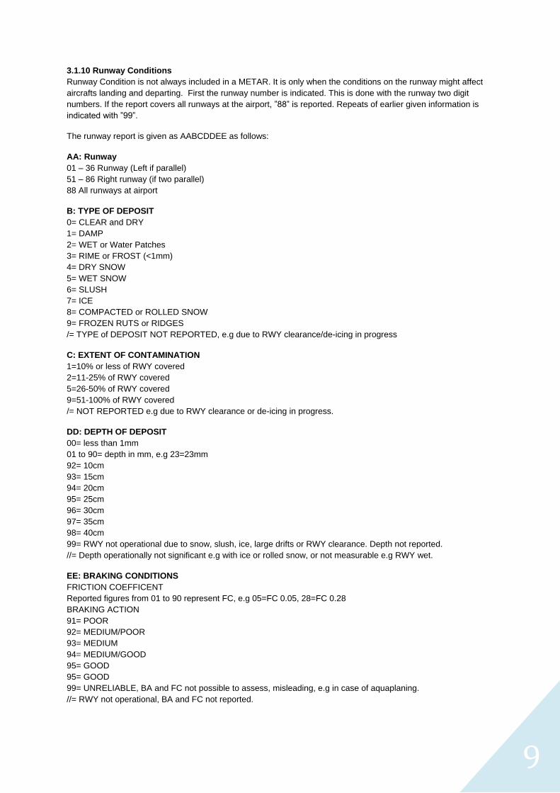
3.1.10 Runway Conditions
Runway Condition is not always included in a METAR. It is only when the conditions on the runway might affect
aircrafts landing and departing. First the runway number is indicated. This is done with the runway two digit
numbers. If the report covers all runways at the airport, ”88” is reported. Repeats of earlier given information is
indicated with ”99”.
The runway report is given as AABCDDEE as follows:
AA: Runway
01 – 36 Runway (Left if parallel)
51 – 86 Right runway (if two parallel)
88 All runways at airport
B: TYPE OF DEPOSIT
0= CLEAR and DRY
1= DAMP
2= WET or Water Patches
3= RIME or FROST (<1mm)
4= DRY SNOW
5= WET SNOW
6= SLUSH
7= ICE
8= COMPACTED or ROLLED SNOW
9= FROZEN RUTS or RIDGES
/= TYPE of DEPOSIT NOT REPORTED, e.g due to RWY clearance/de-icing in progress
C: EXTENT OF CONTAMINATION
1=10% or less of RWY covered
2=11-25% of RWY covered
5=26-50% of RWY covered
9=51-100% of RWY covered
/= NOT REPORTED e.g due to RWY clearance or de-icing in progress.
DD: DEPTH OF DEPOSIT
00= less than 1mm
01 to 90= depth in mm, e.g 23=23mm
92= 10cm
93= 15cm
94= 20cm
95= 25cm
96= 30cm
97= 35cm
98= 40cm
99= RWY not operational due to snow, slush, ice, large drifts or RWY clearance. Depth not reported.
//= Depth operationally not significant e.g with ice or rolled snow, or not measurable e.g RWY wet.
EE: BRAKING CONDITIONS
FRICTION COEFFICENT
Reported figures from 01 to 90 represent FC, e.g 05=FC 0.05, 28=FC 0.28
BRAKING ACTION
91= POOR
92= MEDIUM/POOR
93= MEDIUM
94= MEDIUM/GOOD
95= GOOD
95= GOOD
99= UNRELIABLE, BA and FC not possible to assess, misleading, e.g in case of aquaplaning.
//= RWY not operational, BA and FC not reported.
10
3.2 VMC - Visual Meteorological Conditions
Please note that the VMC minima differ between countries and you have to refer to your local vACC to get the
minimums for your country. If no such values are available you can use the ones below.
During a VFR-flight certain VMC-minima, i.e. certain limits for visibility and cloud base has to be fulfilled. These
limits depend on what altitude and in what airspace the flight is conducted. A pilot may not fly VFR if the weather
is below these minima.
Clearance to fly below the minima as special-VFR can be obtained by ATC, but such a clearance can only be
given for flights within a CTR and is only valid for an approach or departure to or from the airport when the
weather is above minima outside the CTR.
The opposite of VMC is instrument metrological conditions (IMC), which is considered to prevail whenever VMC
minima aren’t be met.
In our virtual world ATC and pilots may have different weather on the same spot and time because of software
and updates from servers. It is therefore good practice to leave the decision if a flight shall be cancelled or
postponed due to VMC to the pilot.
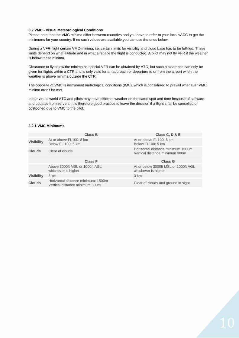
3.2.1 VMC Minimums
Class B Class C, D & E
Visibility At or above FL100: 8 km Below FL 100: 5 km
At or above FL100: 8 km Below FL100: 5 km
Clouds Clear of clouds Horizontal distance minimum 1500m Vertical distance minimum 300m
Class F Class G
Above 3000ft MSL or 1000ft AGL whichever is higher
At or below 3000ft MSL or 1000ft AGL whichever is higher
Visibility 5 km 3 km
Clouds Horizontal distance minimum: 1500m Vertical distance minimum 300m
Clear of clouds and ground in sight
11
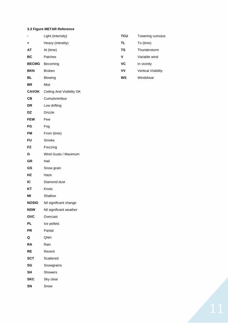
3.3 Figure METAR Reference
- Light (intensity)
+ Heavy (intestity)
AT At (time)
BC Patches
BECMG Becoming
BKN Broken
BL Blowing
BR Mist
CAVOK Ceiling And Visibility OK
CB Cumulonimbus
DR Low drifting
DZ Drizzle
FEW Few
FG Fog
FM From (time)
FU Smoke
FZ Frezzing
G Wind Gusts / Maximum
GR Hail
GS Snow grain
HZ Haze
IC Diamond dust
KT Knots
MI Shallow
NOSIG Nil significant change
NSW Nil significant weather
OVC Overcast
PL Ice pellets
PR Partial
Q QNH
RA Rain
RE Recent
SCT Scattered
SG Snowgrains
SH Showers
SKC Sky clear
SN Snow
TCU Towering cumulus
TL To (time)
TS Thunderstorm
V Variable wind
VC In vicinity
VV Vertical Visibility
WS Windshear

Page 12 of 14