of Treatments on and of fruits Zaghloul and Samany Cultivars

Amir I. Zaghloul
ECE Department, Virginia Tech
and U.S. Army Research Laboratory, Adelphi, MD 20783
Presentation at Virginia Tech, Blacksburg
March 19, 2014
Metamaterials,
Metasurfaces, and
Nanotechnology, and their
Applications to Antennas,
Sensors, and Cognitive Radar
Outline
• Introduction
• Metamaterials • Negative Refractive Index
• Periodic and Random Material
• Application to Enhanced Dipole Antenna
• Application to Rotman lens
• Metasurfaces • Electromagnetic Band-Gap Surfaces
• Wideband EBG Surfaces
• Adaptive and Active Reflection Phase Surfaces
• Application to Spiral Antennas
• Application to Cognitive Radar
• Nanotechnology • Carbon Nano-Tubes
• CNT Patches
• Application to Gas Sensors
• Application to Polarization-Selective Patches
• Conclusions

ACADEMIA
DEFENSE LABORATORIES
INDUSTRY
People
Resources
Facilities
Efficient,
effective and
agile research
system
Ideal State

• Campus-like environment with collaborative space
• Ready access for all partners including foreign nationals
• Expansion of academic programs & collaboration
• Access to world-renown facilities and resources
• Synergistic with MD and DC metro area entrepreneur
community
• Better focus of small business innovative research
(SBIR) investments
Open Campus
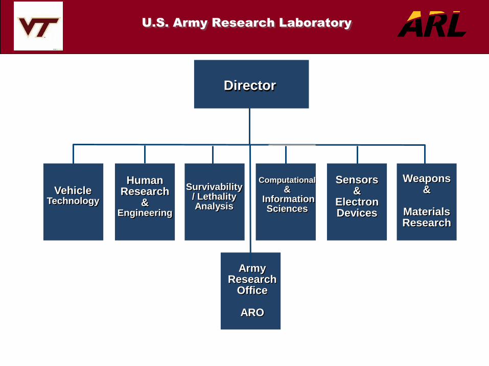
U.S. Army Research Laboratory
Director
Survivability / Lethality Analysis
Computational &
Information Sciences
Sensors &
Electron Devices
Human Research
& Engineering
Vehicle Technology
Weapons &
Materials Research
Army Research
Office
ARO

Outline
• Introduction
• Metamaterials • Negative Refractive Index
• Periodic and Random Material
• Application to Enhanced Dipole Antenna
• Application to Rotman Lens
• Metasurfaces • Electromagnetic Band-Gap Surfaces
• Wideband EBG Surfaces
• Adaptive and Active Reflection Phase Surfaces
• Application to Spiral Antennas
• Application to Cognitive Radar
• Nanotechnology • Carbon Nano-Tubes
• CNT Patches
• Application to Gas Sensors
• Application to Polarization-Selective Patches
• Conclusions

Metamaterials
A Definition: A class of engineered materials that
exhibit highly beneficial electromagnetic properties,
which are not naturally occurring or common
synthetic materials
, ,
, ,
Right-Hand (RH) Materials
Left-Hand (LH) Materials or
Double Negative Materials
Band-Gap Materials
Band-Gap Materials

Some Specific Metamaterials
Design Goals
• Metamaterials present themselves as an additional “tool set” for designing and enhancing antenna performance
– Investigate metamaterial magnetic ground planes to reduce
planar antenna sizes
• Applicable to conformal platform applications
– Investigate metamaterials to impedance match embedded antennas in platform thus improving bandwidth
– Investigate metamaterials to reduce mutual coupling between antennas operating at different frequencies
• Mitigate co-site interference
• Improve array performance
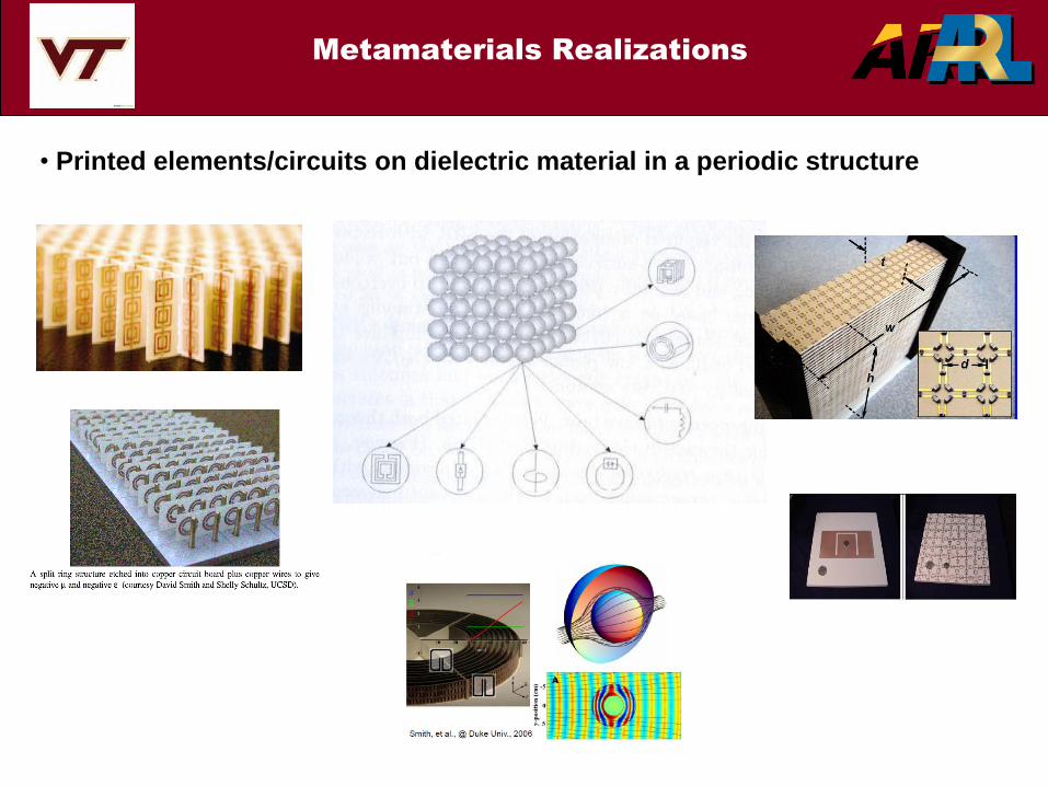
Metamaterials Realizations
• Printed elements/circuits on dielectric material in a periodic structure
University of Michigan – K. Sarabandi
Metamaterial Antennas - ones made from ideal homogenized
metamaterials where the behavior of the unit cells gives effective
macroscopic parameters.
Metamaterial inspired - designs that are realized from understanding
metamaterial concepts, but cannot be called metamaterials (e.g., an
antenna constructed with one “unit cell.”) Often the designs are realized
by a few metallic inclusions (e.g., split ring resonators,) but could have
been realized using well-known traditional methods.
Metamaterial and Metamaterial-
Inspired Antennas
UNCLASSIFIED – APPROVED FOR PUBLIC RELEASE

Victor Veselago
Writes a theoretical
Paper discussing the
Implications of double
Negative materials.
ARL fabricates a class
Of metamaterial at RF
For optimization of antenna
performance.
ARL fabricates double
negative test structures
for proof of feasibility
ARL Measures University of
Michigan/CERDEC Metamaterial
structure to validate performance
enhancement.
ARL develops Volumetric
Randomly Oriented Unit Cells
for Isotropic Performance
ARL is contracting agent
With MetaMaterials, Inc
for Metaferrite antenna
development
ARL identifies significant
Modeling issues and defines
needs for the MSME
2000
1967
2007
2008
2009
2010
2011
General
Atomics/Metamaterial
Belt Antenna for the
Soldier
Duke Univ. Metamaterial
Rotman lens
Metamaterials can
be used to mitigate
“hot spots” Metamaterials can
integrate antennas
into armor
Metamaterials can
be used to broadband
(impedance match) antennas
Accurate analytical and numerical tool for
periodic-metal-insert metamaterials
Random-metal-insert metamaterials for
broadband applications
Analytical and numerical tools for general
metamaterial configurations.
2012
Prototype Antennas
Fabricated and Measured
2013….
ARL field tests
Metamaterial antennas
On Army platforms
Army/ARL RF Metamaterials
Research & Development
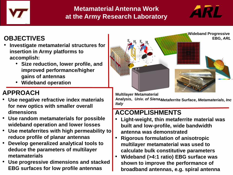
OBJECTIVES • Investigate metamaterial structures for
insertion in Army platforms to
accomplish:
• Size reduction, lower profile, and
improved performance/higher
gains of antennas
• Wideband operation
ACCOMPLISHMENTS • Light-weight, thin metaferrite material was
built and low-profile, wide bandwidth
antenna was demonstrated
• Rigorous formulation of anisotropic
multilayer metamaterial was used to
calculate bulk constitutive parameters
• Wideband (>4:1 ratio) EBG surface was
shown to improve the performance of
broadband antennas, e.g. spiral antenna
APPROACH • Use negative refractive index materials
for new optics with smaller overall
dimensions
• Use random metamaterials for possible
wideband operation and lower losses
• Use metaferrites with high permeability to
reduce profile of planar antennas
• Develop generalized analytical tools to
deduce the parameters of multilayer
metamaterials
• Use progressive dimensions and stacked
EBG surfaces for low profile antennas
Metamaterial Antenna Work
at the Army Research Laboratory
l
, μ ε
extE extH
, μ ε
extE extH
Metaferrite Surface, Metamaterials, Inc
Wideband Progressive
EBG, ARL
Multilayer Metamaterial
Analysis, Univ. of Siena,
Italy
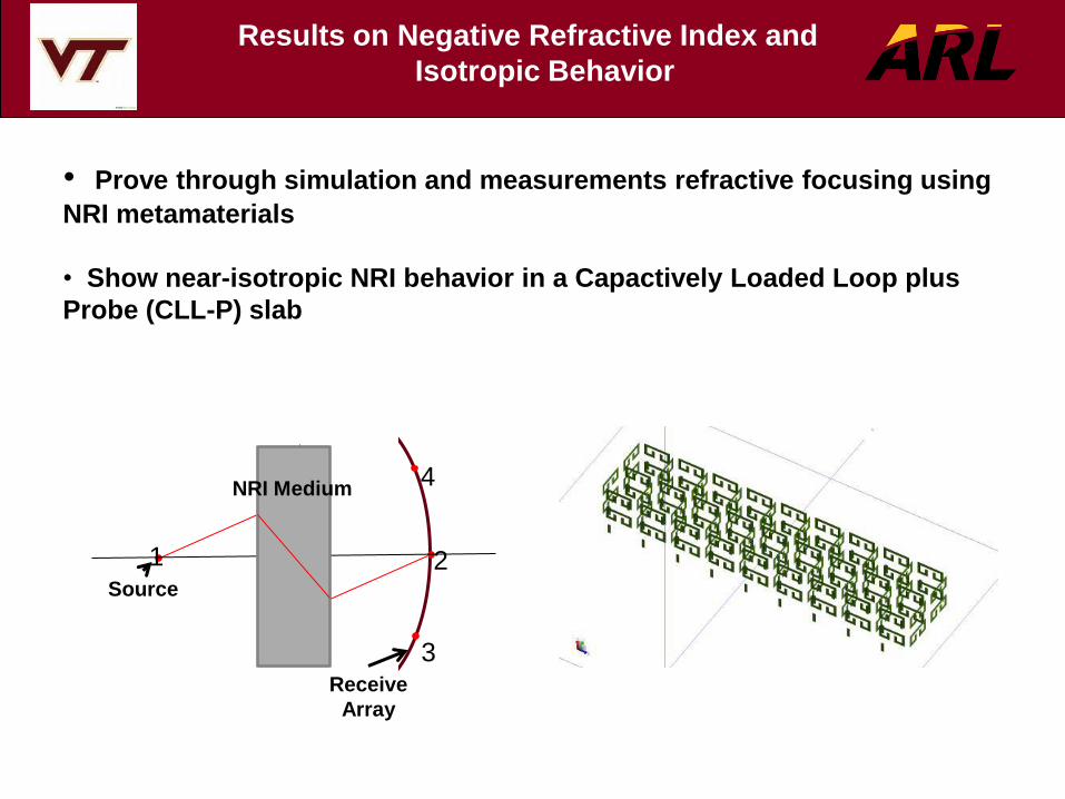
Results on Negative Refractive Index and
Isotropic Behavior
• Prove through simulation and measurements refractive focusing using
NRI metamaterials
• Show near-isotropic NRI behavior in a Capactively Loaded Loop plus
Probe (CLL-P) slab
Receive
Array
Source
NRI Medium
1 2
3
4
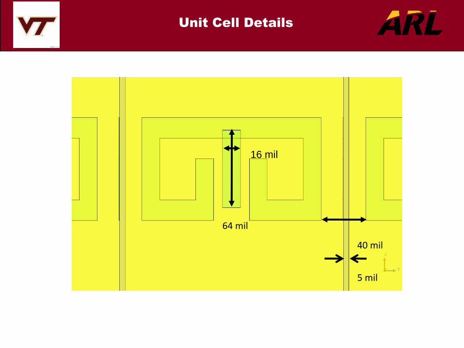
Unit Cell Details
40 mil
5 mil
64 mil
16 mil

Refractive Focusing Using
Negative-Refractive-Index Metamaterials
• 3D view of problem setup
• Height of dielectric 61 mil
• Dielectric constant 2.3
• Frequency range 45 – 47 GHz
• Wavelength at 46 GHz: 6.52 mm, 257 mil

Refractive Focusing Using
Negative-Refractive-Index Metamaterials
Frequency, GHz
45.0 45.5 46.0 46.5 47.0
dB
-30.0
-25.0
-20.0
-15.0
-10.0
-5.0
S11
S31
S21
Frequency, GHz
45.0 45.5 46.0 46.5 47.0
dB
-35.0
-30.0
-25.0
-20.0
-15.0
-10.0
-5.0
S11
S31
S21
Simulated S-Parameters
without Metamaterial
Simulated S-Parameters
with Metamaterial

Refractive Focusing Using
Negative-Refractive-Index Metamaterials
S11 blue, S21 red, S31 green, S21w/o mm black
-20
-15
-10
-5
45 46 47
Frequency, GHz
Retu
rn/I
nsert
ion
Lo
ss,
dB
S11 with metamaterial
S21 with metamaterial
S31 with metamaterial
S21 without metamaterial
Measured S-Parameters

Realization of Negative-Refractive-Index in
a Parallel Slab
• Full-wave simulation of parallel slab
• Unit cell is a Capacitively Loaded Loop + Probe (CLL-P)
• Refractive index is calculated using Snell’s Law and S-parameters
=> agreement
• Uniform negative refractive index at wide inclined angles =>
isotropic
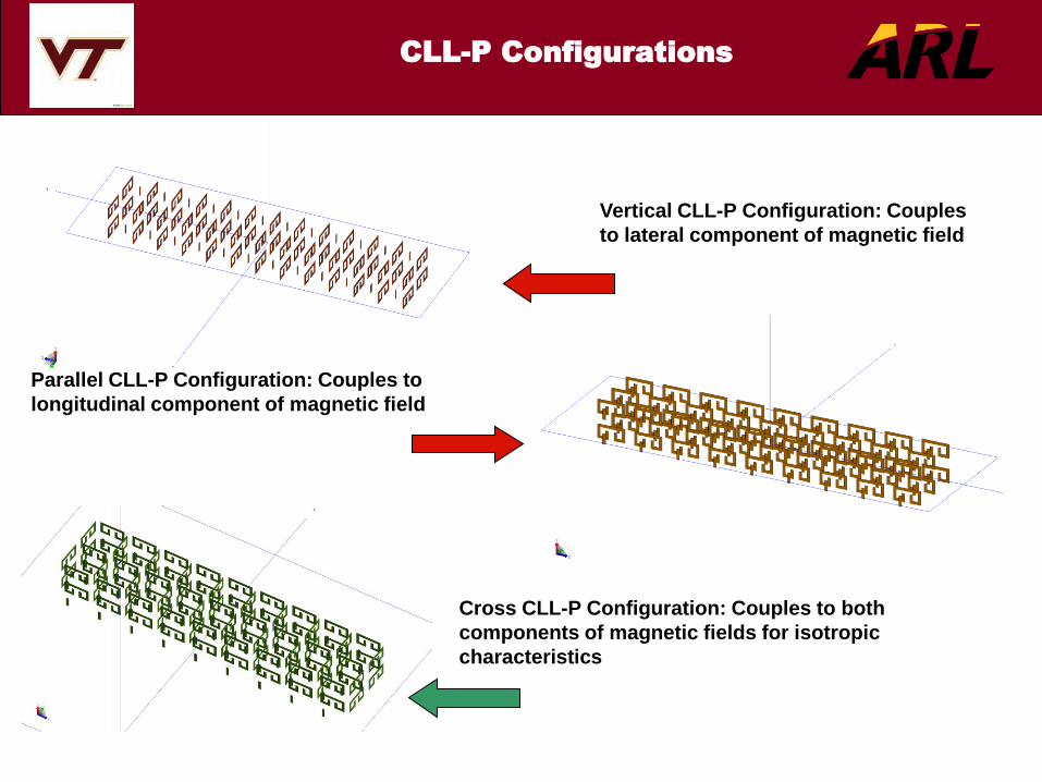
CLL-P Configurations
Cross CLL-P Configuration: Couples to both
components of magnetic fields for isotropic
characteristics
Vertical CLL-P Configuration: Couples
to lateral component of magnetic field
Parallel CLL-P Configuration: Couples to
longitudinal component of magnetic field
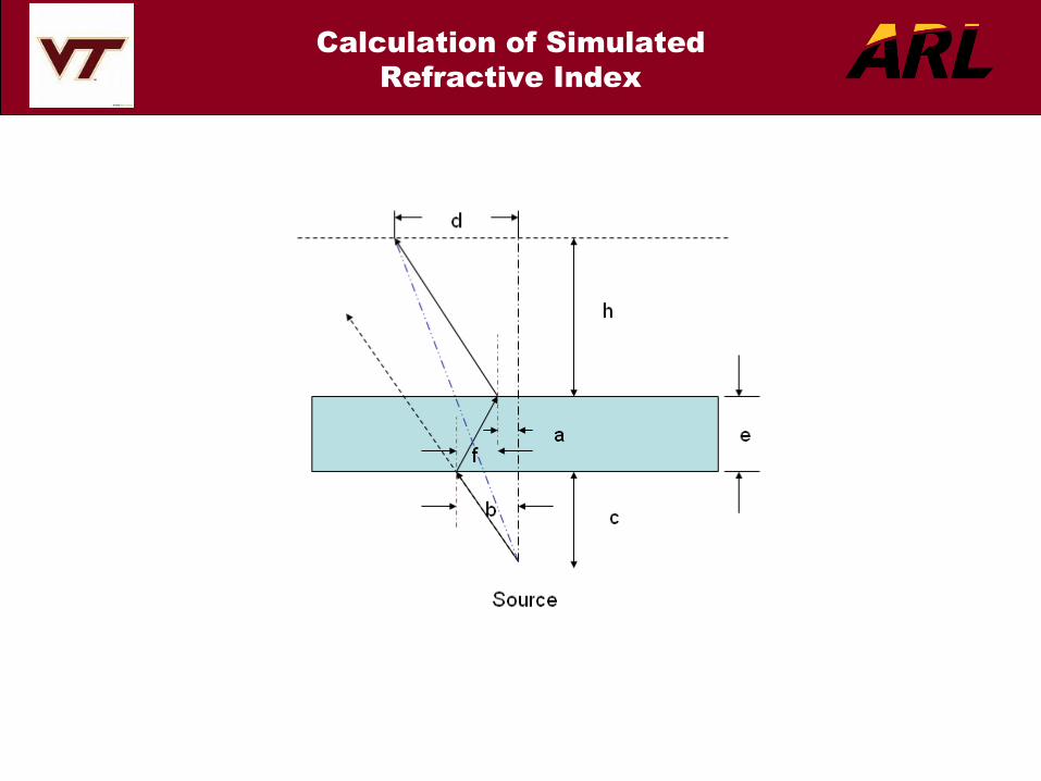
Calculation of Simulated
Refractive Index

Comparison of the Refractive
Index for Different Types of
CLL Slabs
Isotropic negative refractive index in cross-arranged CLL slab
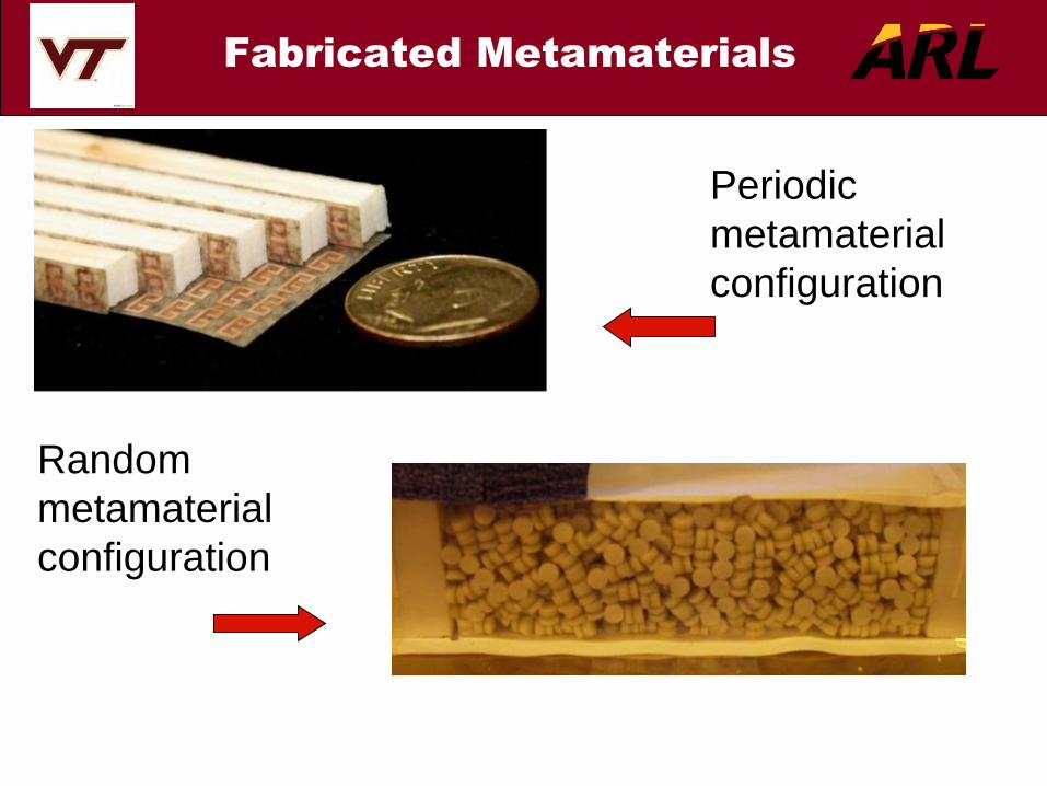
Fabricated Metamaterials
Periodic
metamaterial
configuration
Random
metamaterial
configuration

Random Metamaterial Unit
Rohacell
Rohacell
Printed CLL
Printed Probe
Duroid

• Develop wideband control of
metamateral transmission and
reflection properties as an alternative
to adaptive narrowband tuning
• Application-specific metamaterials:
band-pass, band-stop, reflection-
enhanced surfaces
• Explore the characteristics of randomly
oriented cells in metamaterials:
− Broader transmission/reflection
bandwidth
− Applied to fabrication disorders in
otherwise periodic metamaterials
− Study orthogonal incidences and
polarization properties
Periodic Lattice with Uniform Cells
Random Cells
Periodic Lattice with Disordered Cells
Disordered and Random
Metamaterials
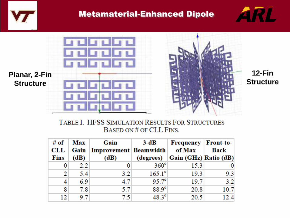
Metamaterial-Enhanced Dipole
Planar, 2-Fin
Structure
12-Fin
Structure

Improved Gain and Radiation
Pattern of Enhanced Dipole
Radiation Pattern
of Planar, 2-Fin
Structure
Radiation
Pattern of 12-Fin
Structure

A Metamaterial-Loaded Rotman Lens
• Use negative refractive
index medium
• New optics pattern
• Reduced size
• Single ray path
AIZ/EA 072209
NRI Medium
Beam Array
Virtual
Beam Array
Receive
Array
Physical Size Size Reduction
Metamaterial
Metamaterial

Outline
• Introduction
• Metamaterials • Negative Refractive Index
• Periodic and Random Material
• Application to Enhanced Dipole Antenna
• Application to Rotman Lens
• Metasurfaces • Electromagnetic Band-Gap Surfaces
• Wideband EBG Surfaces
• Adaptive and Active Reflection Phase Surfaces
• Application to Spiral Antennas
• Application to Cognitive Radar
• Nanotechnology • Carbon Nano-Tubes
• CNT Patches
• Application to Gas Sensors
• Application to Polarization-Selective Patches
• Conclusions

• EBG structures are usually periodic
• High surface impedance
• Do not support surface waves
• Useful when mounting an antenna close to a ground plane
• EBG structures are compact in size, have low loss, and
can be integrated into an antenna
Metasurfaces
Example: Electromagnetic Band
Gap (EBG) Surfaces

2010 National Radio Science Meeting, Boulder| Session BS2-3.
• In phase reflection of the wave
• Band Gap is the frequencies where the
reflected phase is between +900 and -900
• Usually narrowband
Regular EBG Structures

Reflection Phase off EBG Surfaces
Mushroom EBG Configuration and Reflection Phase*
Variation of Frequency Response of Reflection
Phase with Patch Dimensions** *Sievenpiper et al., IEEE Trans MT&T, Nov 1999
** Nakano et al., IEEE Trans A&P, May 2009
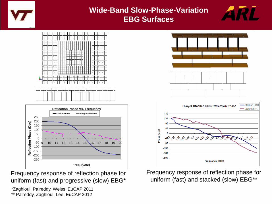
Wide-Band Slow-Phase-Variation
EBG Surfaces
Reflection Phase Vs. Frequency
-250
-200
-150
-100
-50
0
50
100
150
200
250
9 10 11 12 13 14 15 16 17 18 19 20
Freq. (GHz)
Refl
ec
tio
n P
ha
se
(D
eg
)
Uniform EBG Progressive EBG
Frequency response of reflection phase for
uniform (fast) and progressive (slow) EBG*
Frequency response of reflection phase for
uniform (fast) and stacked (slow) EBG**
*Zaghloul, Palreddy. Weiss, EuCAP 2011
** Palreddy, Zaghloul, Lee, EuCAP 2012
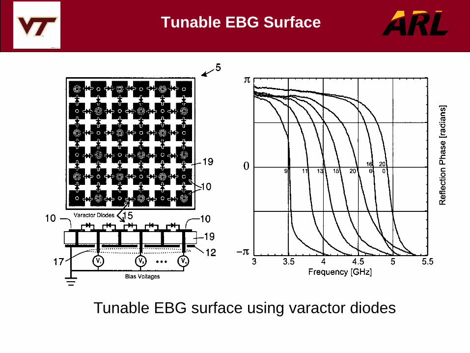
Tunable EBG Surface
Tunable EBG surface using varactor diodes
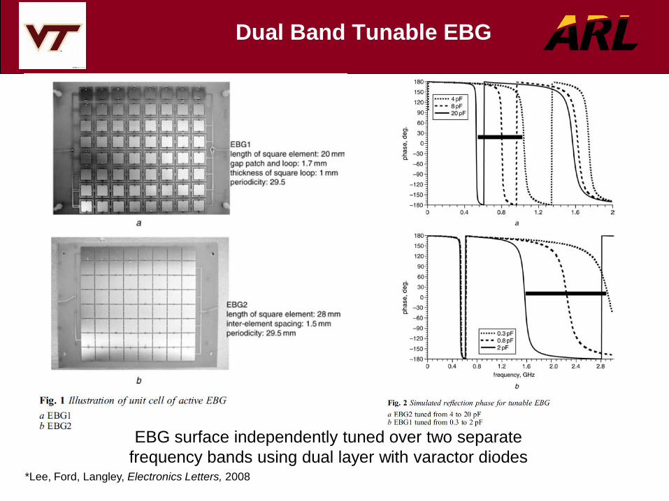
Dual Band Tunable EBG
EBG surface independently tuned over two separate
frequency bands using dual layer with varactor diodes *Lee, Ford, Langley, Electronics Letters, 2008

Tunable Surface Using Distributed
MEMS
S21-Parameter for unit EBG cell Schematic of unit EBG cell
Top view of tunable structure
*Zhang et al., IEEE Nano/Micro Engineered, 2009

2010 National Radio Science Meeting, Boulder| Session BS2-3.
• Formed by cascading Uniform EBGs of same height
• Resonate close to one another
• Has a wider band gap than regular EBG
EBG-Backed Spiral Antenna

• Computed using FEKO
• Reflection phase computed just above the EBG surface
• Notice that the Progressive EBG structure has wider band gap.
Reflection Phase Comparison
2010 National Radio Science Meeting, Boulder| Session BS2-3.
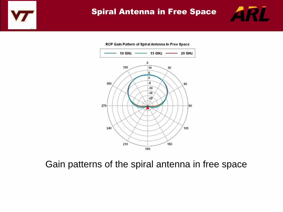
Gain patterns of the spiral antenna in free space
Spiral Antenna in Free Space

Gain patterns of the spiral antenna near uniform EBG
Spiral Antenna near Uniform
EBG

Gain patterns of the spiral antenna near progressive EBG
Spiral Antenna near
Progressive EBG

Return Loss comparison of the spiral antenna under
different loading conditions
Return Loss Comparison

Boresight gain comparison of the spiral antenna under
different loading conditions
Boresight Gain Comparison

Boresight axial ratio comparison of the spiral antenna
under different loading conditions
Axial Ratio Comparison

• Higher gain and higher front-to-back ratio with progressive EBG
• Better boresight axial ratio performance with progressive EBG
than Uniform EBG
• Uniform height progressive EBG structure has a wider band gap,
compared to the regular EBG structure
• Accomplished with low profile that is afforded by the reflection
phase characteristics of the broadband EBG
• This low profile is in contrast with the higher profile design that
uses PEC-backed or absorber-backed cavities
• Gain patterns of the antenna near progressive EBG are cleaner &
smoother, like the case in free space, compared to the case near
uniform EBG
Features of Spiral Antenna near
Progressive EBG

• Cognitive Radar is based on learning through interactions of
the radar with the environment
• Information is facilitated by feedback from the receiver to
the transmitter
• Information on target is deduced through processing of
radar returns
• Environment or channel data include reflection phase and
resonance frequencies of surfaces, which constitute part of
the feedback from the receiver to the transmitter
• Adaptive reflection phase control can be a key function
Application of Adaptive
Metasurfaces to Cognitive Radar

Block diagram of cognitive radar viewed as a dynamic closed-
loop feedback system*
* S. Haykin, “Cognitive Radar, A way of the future,” IEEE Signal Processing Magazine, January 2006
Cognitive Radar Concept

Quotes from S. Haykin
• For the radar to be cognitive, adaptivity has to be extended to the
transmitter too
• The function of the radar-scan analyzer is to provide the receiver
with information on the environment
• The selection of waveforms to be used for adaptive radar
transmission is application dependent
• There is much that we can learn from the echo-location system of
a bat
• An echo-locating bat can pursue and capture its target with a
facility and success rate that would be the envy of a radar engineer

Adaptive Reflection Phase
• Adaptively control the environment, primarily reflection
function
• Function of phase variation can be controlled by transmitter
and shared by receiver
• Narrow-band fast phase change or wide-band slow phase
change versus frequency
• Introduces false target information in radar jamming
systems
• Can be effective in Digital Radio Frequency Memory
(DRFM) techniques

Outline
• Introduction
• Metamaterials • Negative Refractive Index
• Periodic and Random Material
• Application to Enhanced Dipole Antenna
• Application to Rotman Lens
• Metasurfaces • Electromagnetic Band-Gap Surfaces
• Wideband EBG Surfaces
• Adaptive and Active Reflection Phase Surfaces
• Application to Spiral Antennas
• Application to Cognitive Radar
• Nanotechnology • Carbon Nano-Tubes
• CNT Patches
• Application to Gas Sensors
• Application to Polarization-Selective Patches
• Conclusions
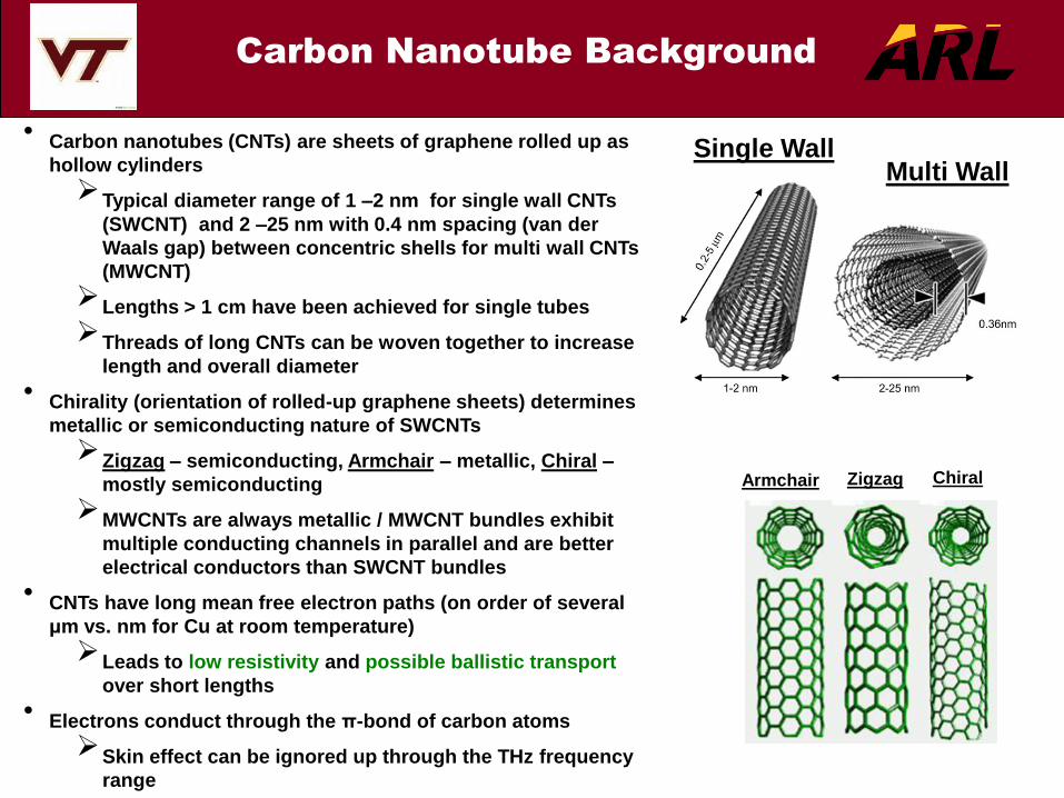
Carbon Nanotube Background
• Carbon nanotubes (CNTs) are sheets of graphene rolled up as
hollow cylinders
Typical diameter range of 1 –2 nm for single wall CNTs
(SWCNT) and 2 –25 nm with 0.4 nm spacing (van der
Waals gap) between concentric shells for multi wall CNTs
(MWCNT)
Lengths > 1 cm have been achieved for single tubes
Threads of long CNTs can be woven together to increase
length and overall diameter
• Chirality (orientation of rolled-up graphene sheets) determines
metallic or semiconducting nature of SWCNTs
Zigzag – semiconducting, Armchair – metallic, Chiral –
mostly semiconducting
MWCNTs are always metallic / MWCNT bundles exhibit
multiple conducting channels in parallel and are better
electrical conductors than SWCNT bundles
• CNTs have long mean free electron paths (on order of several
μm vs. nm for Cu at room temperature)
Leads to low resistivity and possible ballistic transport
over short lengths
• Electrons conduct through the π-bond of carbon atoms
Skin effect can be ignored up through the THz frequency
range
Armchair Zigzag Chiral
Single Wall Multi Wall

Carbon Nanotube Thread
Conductivity Simulation
• Conductivity simulated for thin copper cylinder, double-
wall carbon nanotube and 1-ply, 3-ply and 3x3 (9)-ply
carbon nanotube thread
3.4 Å van der Waals spacing between nanotubes in
CNT thread
• CNT thread predicted to yield orders of magnitude higher
conductivity above single carbon nanotube
• Simulations agree well with measured resistivity of CNT
thread (1e-4 Ω-cm σ≈ 1e6 S/m), and confirm known
conductivity of copper (~5.96e7 S/m)
• Increasing CNT thread/rope ply (diameter and conductive
paths) should yield improved conductivity
e =1.602e-19 coulombs me = 9.11e-31 kg
Ne = 8.46e28 electrons/m3 v = (2.47e-14)
-1
ħ = 1.0546e-34 m2kg/s vF = 9.71e5 m/s
R = CNT thread radius a = CNT radius
x = intertube CNT spacing = 2a + 3.4 Å
Prototype Radius
(µm)
Double-wall CNT 0.005
1-ply CNT thread 12.5
3-ply CNT thread 37.5
3x3-ply CNT thread 112.5
30-gauge Cu wire 127.5
15-gauge Cu wire 725
totaltotal
square
circle NNRR
R
A
A
4;
422
2
Approximate Number of Carbon
Nanotubes in Circular CNT Bundle / Thread
Number of Carbon Nanotubes in
Rectangular CNT Bundle
12/3
2;
2
x
aRN
x
aRN LW
LWouterL
LWtotal NNNN
NNN 2;2
ja
vej F
SWNT
2
22
Conductivity of
Double-wall Nanotube
N
q
q
SWNTMWNT
1
)(
SWNTDWNT 2
DWNTtotalBundle N
Conductivity of
CNT Bundle / Thread

Carbon Nanotube Gas Sensor
Background
• When subjected to certain oxidizing/reducing
gases, εr and σ of CNTs are altered
Examples: He, Ar, N2, O2, NH3
• Charge transfer between the reacting gas
molecules and the CNTs are the most likely
mechanism for this occurrence
Gas molecules act as either electron donors or
acceptors to CNTs
• Process is reversible (εr and σ return to original
values over recovery time)
• CNT gas sensor achieved by coating a microwave
cavity resonator with a thin layer of randomly
scattered SWNTs and/or aligned MWNTs
Resonator frequency shifts by small, but measurable
amount in direct response to the change in εr and σ
caused by the presence of the reacting gas
Goal: Incorporate CNT gas sensing capabilities
with RF properties to yield complete
lightweight, durable wireless gas sensor
Carbon nanotube
Oxidizing/Reducing Gas
Molecule(s)
1
2
21
2
2
1
00
rrrr
f
c
fW
2/1
1212
1
2
1
W
trreff
)8.0()258.0(
)264.0()3.0(
412.0
t
Wt
W
t
L
eff
eff
22 eff
L L
30
(in GHz)
cm
rf
X
Y
Z
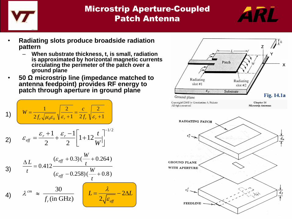
Microstrip Aperture-Coupled
Patch Antenna
1)
2)
3)
4)
• Radiating slots produce broadside radiation pattern
– When substrate thickness, t, is small, radiation is approximated by horizontal magnetic currents circulating the perimeter of the patch over a ground plane
• 50 Ω microstrip line (impedance matched to antenna feedpoint) provides RF energy to patch through aperture in ground plane

Carbon Nanotube Meshed Thread
Patch Antenna Concept
• Apply carbon nanotube thread/yarn to create
meshed patch antenna structure
• Alternate thread in mesh with highly conductive
MWNT thread (RF radiators) and semiconducting
SWNT thread (dielectric buffer / “gas sensing”
mechanism)
MWNT threads are main conductive elements for
radiating meshed thread patch antenna
SWNT threads have high # of defects to limit their
conductivity and serve as dielectric buffer threads
Defect sites on SWNT threads provide more
locations for reactive gas molecules to donate or
accept electrons increases gas sensing
mechanism
• In the presence of oxidizing/reducing gases, εr of
SWNT dielectric buffer threads will change and
resonant frequency of patch antenna will shift
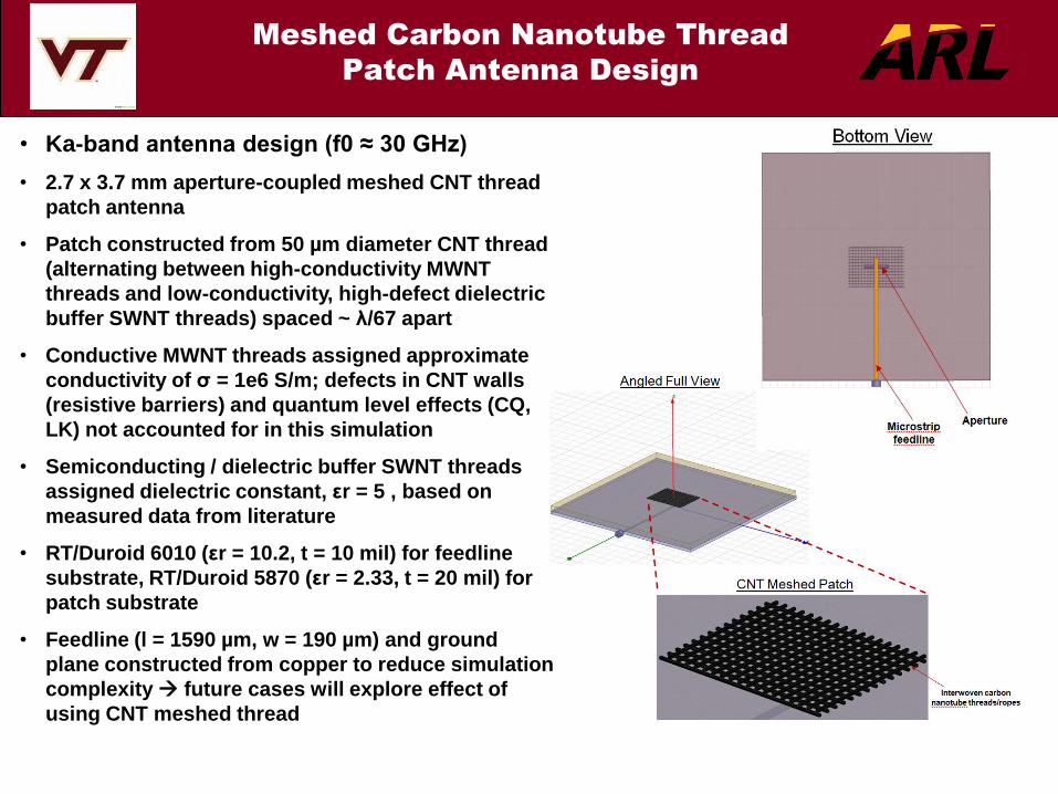
Meshed Carbon Nanotube Thread
Patch Antenna Design
• Ka-band antenna design (f0 ≈ 30 GHz)
• 2.7 x 3.7 mm aperture-coupled meshed CNT thread
patch antenna
• Patch constructed from 50 µm diameter CNT thread
(alternating between high-conductivity MWNT
threads and low-conductivity, high-defect dielectric
buffer SWNT threads) spaced ~ λ/67 apart
• Conductive MWNT threads assigned approximate
conductivity of σ = 1e6 S/m; defects in CNT walls
(resistive barriers) and quantum level effects (CQ,
LK) not accounted for in this simulation
• Semiconducting / dielectric buffer SWNT threads
assigned dielectric constant, εr = 5 , based on
measured data from literature
• RT/Duroid 6010 (εr = 10.2, t = 10 mil) for feedline
substrate, RT/Duroid 5870 (εr = 2.33, t = 20 mil) for
patch substrate
• Feedline (l = 1590 µm, w = 190 µm) and ground
plane constructed from copper to reduce simulation
complexity future cases will explore effect of
using CNT meshed thread

Simulated S11
for Meshed CNT Thread
vs. Solid Copper Patch Antenna
• Meshed CNT thread patch design yields center frequency shift (f0) and bandwidth reduction
when compared with traditional solid copper patch design
2 GHz (7%) f0 shift: from 29.6 GHz to 27.85 GHz
400 MHz (~16 %) bandwidth (S11 = -10 dB) reduction: from 2.5 GHz to 2.1 GHz

Simulated Gain for Meshed Carbon
Nanotube Thread Patch Antenna
• Broadside radiation pattern maintained with CNT meshed patch antenna
• Meshed CNT thread patch design yields small gain reduction when compared with traditional
solid metal patch design
0.46 dB (~7 %) reduction: from 6.79 dBi to 6.33 dBi
Gain reduction likely from resonance shift observed in S11 simulation

Gas Sensor Functionality
Simulation
• From experimental observation, permittivity
(εr) of a thin layer of semiconducting SWNTs
increases linearly when in the presence of
increasing concentrations of ammonia gas
(NH3)
• Estimated change from εr = 5 to εr = 5.15 in
presence of 1000 ppm of NH3, then εr = εr +
0.15 with each additional 3000 ppm NH3
Permittivity changes applied to SWNT
thread model to simulate gas sensing
for meshed thread patch antenna
• Small, but measurable resonant frequency
shift predicted to occur with increasing
concentrations of NH3 around the meshed
CNT thread patch antenna
-60 MHz shift in f0, from 27.84 GHz to
27.78 GHz
• Frequency shift is small enough to guarantee
continuous bandwidth for TX/RX
communications functionality
• Adding PABS to SWNT will increase the
sensitivity of gas detection with ability to
sense very low, and more practical levels
εr of semiconducting SWNT buffer
threads varied from 5 to 6 in 0.15
increments to simulate increasing
concentrations of NH3 gas

Polarization Selectivity
In CNT Patch Antennas
-18 -17 -16 -15 -14 -13 -12 -11 -10
-9 -8 -7 -6 -5 -4 -3 -2 -1 0
5 5.5 6 6.5 7 7.5 8 8.5 9 9.5 10 10.5 11 11.5 12 12.5 13
S1V
S2V
S3V
-18 -17 -16 -15 -14 -13 -12 -11 -10
-9 -8 -7 -6 -5 -4 -3 -2 -1 0
5 5.5 6 6.5 7 7.5 8 8.5 9 9.5 10 10.5 11 11.5 12 12.5 13
S1H
S2H
Return Loss for Co-Aligned CNT Patch
Return Loss for Cross-Aligned CNT Patch

Outline
• Introduction
• Metamaterials • Negative Refractive Index
• Periodic and Random Material
• Application to Enhanced Dipole Antenna
• Application to Rotman lens
• Metasurfaces • Electromagnetic Band-Gap Surfaces
• Wideband EBG Surfaces
• Adaptive and Active Reflection Phase Surfaces
• Application to Spiral Antennas
• Application to Cognitive Radar
• Nanotechnology • Carbon Nano-Tubes
• CNT Patches
• Application to Gas Sensors
• Application to Polarization-Selective Patches
• Conclusions

Conclusions
• Metamaterials and metasurfaces define structures that have
been known by different names in the past
• Metamaterial structures may lead to more efficient, smaller
antennas with new features not doable with natural materials
• Metasurfaces provide reflection phases that can reduce
antenna profiles with potential application to cognitive radar
• Carbon nano-tubes have high tensile-strength and light weight,
with high conductivity if used in multiple layers
• CNTs have potential applications in body-worn electronics,
sensors, and polarization selective antennas