METALS INTERNATIONAL LIMITED -...
16
METALS INTERNATIONAL LIMITED Tel: +86-21-6090-0836/60900837/6563 Fax: +86-21-6090-0838 http://www.klsteel.com Email: .[email protected]
Transcript of METALS INTERNATIONAL LIMITED -...

METALS INTERNATIONAL LIMITED
Tel: +86-21-6090-0836/60900837/6563 Fax: +86-21-6090-0838
HUhttp://www.klsteel.comUH Email: [email protected]

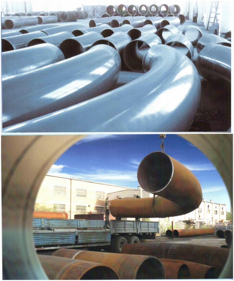
Metals International Limited is a worldwide leading company specializing in hot induction bends
Induction Bending is a controlled means of bending pipes through the application of local heating using
high frequency induced electrical power.
Originally used for the purpose of surface hardening steels, induction technology when used in pipe
bending consists basically of an induction coil placed around the pipe to be bent. The induction coil heats
a narrow, circumferential section of the pipe to a temperature of between 850 and 1100 degrees Celsius
(dependant on the material to be formed). As the correct bending temperature range is reached, the pipe is
moved slowly through the induction coil whilst the bending force is applied by a fixed radius arm
arrangement.
As the bending occurs, the adjacent area forward of the heat band is water or air quenched (or may be
allowed to cool naturally) thereby allowing the cool material to either side of the ‘heat band’ to retain the
integrity of the original material as best as possible. This means of distortion control provides excellent
dimensional accuracy and repeatability.
Although induction bending produces excellent results as far as physical properties are concerned, it must
be noted that there are two important considerations required – firstly the reduction in wall thickness at
the outside (extrados) of the bend and secondly the degree of ovality which is present.
The induction pipe bending process uses induction heating to produce highly accurate bends. The quality
of induction bends is superior to the elbow fitting. Hydro burst tests show that spools with induction
bends fail in the straight pipe and not in the bend, whereas in comparable elbow-based systems the elbow
(inside radius) is always the first to burst. Stress calculations confirm this. The natural tendency to have a
thicker inside wall thus proves to be advantageous and ensures that the bend exceeds the strength of the
straight pipe.
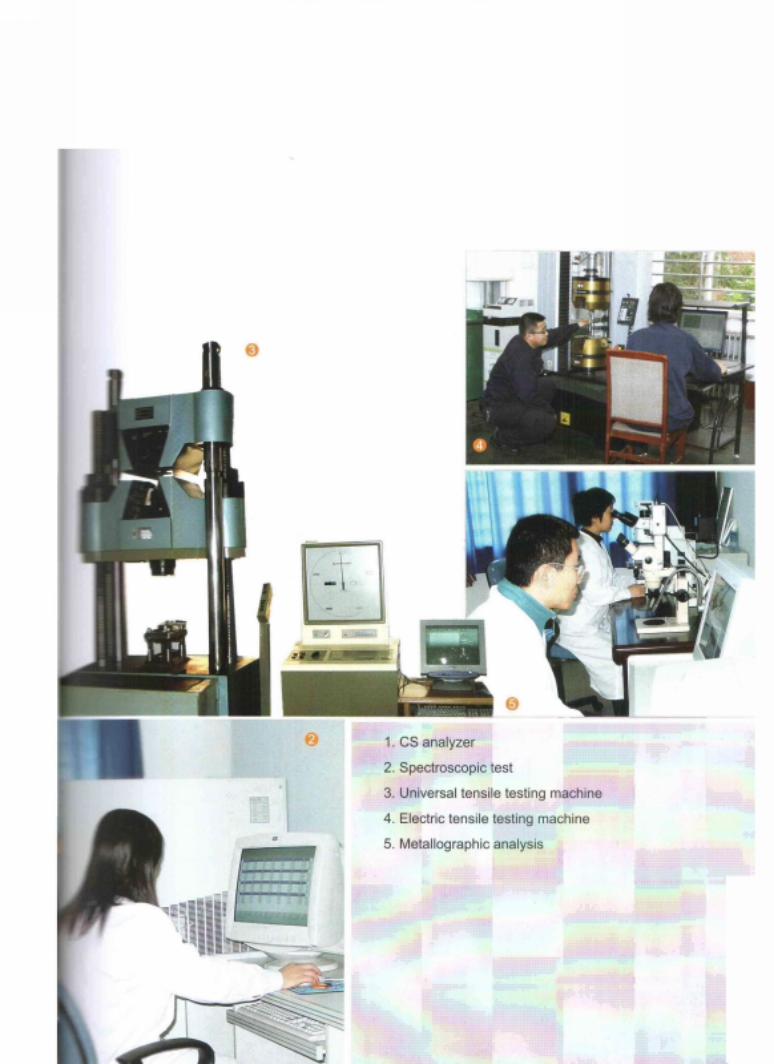
Company is committed to quality products and also treasures its employees who make it happen. Its vast
organizational strength comprises of dedicated and skilled teammates whose core competence lies in
making a good products, a better one. Our product are in compliance with quality control at every
manufacturing stage in accordance with API-5L, API 5LC,API 5D, API 5LD, API 2B, API 5H, ASTM,
and other international specifications. They are also approved by international Third Party Inspection
authorities like DNV, BV,SGS, Moody, TUV, ABS,LR,GL,PED,RINA,KR, NKK, AIB-VINEOTTE,
CEIL, VELOSI, CCSI, etc.
Our goal is to provide high quality products at competitive prices with best service that will ensure
long-term relationships with our customers.

Products Range
Nominal Pipe
Size in
O.D.(m
m)
RADIUS(mm) Angle Tangent Length at Each end
Wall Thickness
(mm) 3D 4D 5D 6D 8D 10D θ
3" 89 267 356 445 534 712 890 90°, 60° 350 Sch STD,
4" 114 342 456 570 684 912 1140 45°, 30° 350
sch10,Sch20,
6" 168 504 672 840 1008 1344 1680 22.5°,
or 350 Sch30,Sch40
,
8" 219 657 876 1095 1314 1752 2190 as per 700
Sch80,Sch 100,
Schu160, XXS, etc.
10" 273 819 1092 1365 1638 2184 2730 the
choice 700 or as per
12" 325 975 1300 1625 1950 2600 3250
of purchase
r 700 the choice
14" 356 1068 1424 1780 2136 2848 3560 700 of purchaser
16" 406 1218 1624 2030 2436 3248 4060 700
18" 457 1371 1828 2285 2742 3656 4570 1000
20" 508 1524 2032 2540 3048 4064 5080 1000
22" 559 1677 2236 2795 3354 4472 5590 1000
24" 610 1830 2440 3050 3660 4880 6100 1000
26" 660 1980 2640 3300 3960 5280 6600 1D
(Outside
28" 711 2133 2844 3555 4266 5688 7110 diameter of
30" 762 2286 3048 3810 4572 6096 7620 bend)or
32" 813 2439 3252 4065 4878 6504 8130 as per
34" 864 2592 3456 4320 5184 6912 8640 the choice
36" 914 2742 3656 4570 5484 7312 9140 of
purchaser
38" 965 2895 3860 4825 5790 7720 9650
40" 1016 3048 4064 5080 6096 8128 10160
42" 1067 3201 4268 5335 6402 8536 10670
44" 1118 3354 4472 5590 6708 8944 11180
46" 1168 3504 4672 5840 7008 9344 11680
48" 1219 3657 4876 6095 7314 9752 12190
50" 1270 3810 5080 6350 7620 10160 12700
52" 1321 3963 5284 6605 7926 10568 13210
54" 1372 4116 5488 6860 8232 10976 13720
56" 1422 4266 5688 7110 8532 11376 14220

Control Points
Bend end preparation:Welding ends to be beveled as per ASME B16.25 or as per specified by purchaser.
Induction Pipe Bending Standard Bend Tolerances
Bend Angle:±1/2°
Bend Radius:±1%
Bend Plane:±1°
End squareness
Size NPS36" and smaller:2.4mm(0.09")
Size Greater than NPS36":3.0mm(0.12")
Linear Dimensions
Size Nps24" and smaller:±5mm(0.19")
Size Greater than NPS 24":±6mm(0.25")
Thinning: <0.10% of the bend nominal wall thickness
or ≤50D/R(%)(R=bend centerline radius,
D=nominal outside diameter of starter stock)
or ≤0.05% of the nominal wall thickness of the matching pipe.
Applied Specification
ANSI/ASME B16.49-2001 Factory-Made Wrought Steel Butt-welding Induction Bends for
Transportation and Distribution Systems
ISO 15590-2 Petroleum and natural gas industries - induction bends, fittings and flanges for pipeline
transportation systems Part 2: Fittings
BS EN 14870-1 Petroleum and natural gas industries.-Induction bends, fittings and flanges for pipeline
transportation systems-Part 1: Induction Bends
MSS SP-75 Specification for High-Test,Wrought, Butt-Welding Fittings