Metallurgical mechanisms in direct laser sintering of Cu...
6
Journal of Alloys and Compounds 438 (2007) 184–189 Metallurgical mechanisms in direct laser sintering of Cu–CuSn–CuP mixed powder Dongdong Gu ∗ , Yifu Shen, Shangqing Fang, Jun Xiao College of Materials Science and Technology, Nanjing University of Aeronautics and Astronautics, 29 Yudao Street, 210016 Nanjing, PR China Received 7 July 2006; received in revised form 13 August 2006; accepted 15 August 2006 Available online 12 September 2006 Abstract This work presents a detailed investigation into the metallurgical mechanisms in direct laser sintering of a multi-component Cu-based metal powder consisting of a mixture of Cu, Cu–10Sn, and Cu–8.4P. The phases, compositions, and microstructures of the laser sintered sample were characterized by XRD, EDX, and SEM. It is found that laser sintering of this powder system is based on the mechanism of liquid phase sintering with the complete melting of the binder Cu–10Sn and the non-melting of the structural metal Cu. The phosphorus element can act as a deoxidizer to prevent both the sintering mixture and the sintered layer from oxidation by formation of P 2 O 5 and CuPO 3 , thereby improving the liquid–solid wettability and the resultant interlayer bonding coherence. The phosphorus element shows a high concentration along grain boundaries in the sintered structure, due to a low mutual solubility of P in Cu and an extremely short thermal cycle of laser sintering. © 2006 Elsevier B.V. All rights reserved. Keywords: Laser processing; Microstructure; Rapid prototyping (RP); Direct metal laser sintering (DMLS); Cu-based metal powder 1. Introduction Direct metal laser sintering (DMLS) is a newly developed rapid prototyping (RP) technique that generates metallic com- ponents in a layer-by-layer fashion using the loose powder and the computer controlled laser [1–4]. DMLS implies layer-wise shaping and consolidation of metal powder to complex shaped three-dimensional (3D) parts with full or near full density in a single process, while minimal or no post-processing steps such as furnace densification or secondary infiltration are required [5–7]. The recent major advance of DMLS research is in the net-shape fabrication of prototypes and the small-volume tool- ing for injection molding and dies casting [8–10]. Although DMLS holds a great potential in fabricating high performance metallic components with controlled microstruc- tures and mechanical properties, it is still in its early stage of development [3,11]. Common problems associated with this process such as balling phenomenon, curling deformation, low sintered density, weak strength, and high surface roughness are ∗ Corresponding author. E-mail addresses: [email protected] (D. Gu), [email protected] (Y. Shen). still difficult to completely overcome [9,12,13]. In fact, DMLS is a complex metallurgical process exhibiting multiple modes of heat and mass transfer, and in some instances, chemical reactions [2,6,14]. However, not much previous work has been focused on the basic principles of DMLS in terms of microstructural evolu- tions, sintering mechanisms, and processing conditions. Further research and understanding of the metallurgical fundamentals of DMLS, therefore, is regarded particularly necessary. In this study, a multi-component Cu-based metal powder was chosen for direct laser sintering. The suitable processing condi- tions of this powder system have been well determined in our previous work [15], so as to obtain a sound sinterability with minor or no balling effect. This paper presents the sintering behavior, phase transformation, and microstructural evolution of the powder during laser sintering, with an overall aim to con- clude generic metallurgical mechanisms in DMLS process. 2. Experimental 2.1. Materials Electrolytic 99% purity Cu powder with an irregular shape and a mean equiv- alent spherical diameter of 54 m, water-atomized CuSn (10 wt.% Sn) powder with an ellipsoidal shape and an average particle size of 28 m, and gas-atomized 0925-8388/$ – see front matter © 2006 Elsevier B.V. All rights reserved. doi:10.1016/j.jallcom.2006.08.040
Transcript of Metallurgical mechanisms in direct laser sintering of Cu...

A
pcwtws©
K
1
rptstsa[ni
ptdps
y
0d
Journal of Alloys and Compounds 438 (2007) 184–189
Metallurgical mechanisms in direct laser sintering ofCu–CuSn–CuP mixed powder
Dongdong Gu ∗, Yifu Shen, Shangqing Fang, Jun XiaoCollege of Materials Science and Technology, Nanjing University of Aeronautics and Astronautics,
29 Yudao Street, 210016 Nanjing, PR China
Received 7 July 2006; received in revised form 13 August 2006; accepted 15 August 2006Available online 12 September 2006
bstract
This work presents a detailed investigation into the metallurgical mechanisms in direct laser sintering of a multi-component Cu-based metalowder consisting of a mixture of Cu, Cu–10Sn, and Cu–8.4P. The phases, compositions, and microstructures of the laser sintered sample wereharacterized by XRD, EDX, and SEM. It is found that laser sintering of this powder system is based on the mechanism of liquid phase sinteringith the complete melting of the binder Cu–10Sn and the non-melting of the structural metal Cu. The phosphorus element can act as a deoxidizer
o prevent both the sintering mixture and the sintered layer from oxidation by formation of P2O5 and CuPO3, thereby improving the liquid–solidettability and the resultant interlayer bonding coherence. The phosphorus element shows a high concentration along grain boundaries in the
intered structure, due to a low mutual solubility of P in Cu and an extremely short thermal cycle of laser sintering.2006 Elsevier B.V. All rights reserved.
etal l
sih[ttro
ctpmboc
eywords: Laser processing; Microstructure; Rapid prototyping (RP); Direct m
. Introduction
Direct metal laser sintering (DMLS) is a newly developedapid prototyping (RP) technique that generates metallic com-onents in a layer-by-layer fashion using the loose powder andhe computer controlled laser [1–4]. DMLS implies layer-wisehaping and consolidation of metal powder to complex shapedhree-dimensional (3D) parts with full or near full density in aingle process, while minimal or no post-processing steps suchs furnace densification or secondary infiltration are required5–7]. The recent major advance of DMLS research is in theet-shape fabrication of prototypes and the small-volume tool-ng for injection molding and dies casting [8–10].
Although DMLS holds a great potential in fabricating higherformance metallic components with controlled microstruc-ures and mechanical properties, it is still in its early stage of
evelopment [3,11]. Common problems associated with thisrocess such as balling phenomenon, curling deformation, lowintered density, weak strength, and high surface roughness are∗ Corresponding author.E-mail addresses: [email protected] (D. Gu),
[email protected] (Y. Shen).
2
2
aw
925-8388/$ – see front matter © 2006 Elsevier B.V. All rights reserved.oi:10.1016/j.jallcom.2006.08.040
aser sintering (DMLS); Cu-based metal powder
till difficult to completely overcome [9,12,13]. In fact, DMLSs a complex metallurgical process exhibiting multiple modes ofeat and mass transfer, and in some instances, chemical reactions2,6,14]. However, not much previous work has been focused onhe basic principles of DMLS in terms of microstructural evolu-ions, sintering mechanisms, and processing conditions. Furtheresearch and understanding of the metallurgical fundamentalsf DMLS, therefore, is regarded particularly necessary.
In this study, a multi-component Cu-based metal powder washosen for direct laser sintering. The suitable processing condi-ions of this powder system have been well determined in ourrevious work [15], so as to obtain a sound sinterability withinor or no balling effect. This paper presents the sintering
ehavior, phase transformation, and microstructural evolutionf the powder during laser sintering, with an overall aim to con-lude generic metallurgical mechanisms in DMLS process.
. Experimental
.1. Materials
Electrolytic 99% purity Cu powder with an irregular shape and a mean equiv-lent spherical diameter of 54 �m, water-atomized CuSn (10 wt.% Sn) powderith an ellipsoidal shape and an average particle size of 28 �m, and gas-atomized

D. Gu et al. / Journal of Alloys and Compounds 438 (2007) 184–189 185
Fm
Cowaddfs
2
(pllsppsTlAF
2
Amrituaawi(
Fd
3
3
sisttaa(ts((subsequently, precipitates again in the form of �-CuSn, leadingto an efficient consolidation of liquid–solid mixture on cooling.Furthermore, Fig. 3 reveals that the P element was presented
ig. 1. SEM image showing the characteristic morphology of the starting powderixture.
uP (8.4 wt.% P) powder with a spherical morphology and a mean particle sizef 16 �m were used in this study. Phosphorus element, taking as a fluxing agent,as added in the form of pre-alloyed Cu–8.4P to improve the wetting char-
cteristics in the powder system. The three components were homogeneouslyispersed according to the Cu:CuSn:CuP weight ratio of 60:30:10 in a cylin-rical vessel with a vacuum pumping system at a rotation velocity of 100 rpmor 90 min. The characteristic morphology of the as-prepared powder mixture ishown in Fig. 1.
.2. Processing
The used DMLS apparatus mainly consisted of a continuous wave CO2
λ = 10.6 �m) laser with a maximum output power of 2000 W, an automaticowder delivery system, and a computer system for process control. Prior to theaser sintering process, a steel substrate was placed on the building platform andeveled. Then, a thin layer of loose powder with the thickness of 0.20 mm waspread on the substrate by the roller. Subsequently, the laser beam scanned theowder bed surface to form a layer-wise profile according to the CAD data of theart. The similar process was repeated until the specimen was finished. The laserintering process was performed in ambient atmosphere at room temperature.he following laser processing parameters were used: spot size of 0.30 mm,
aser power of 375 W, scan speed of 0.04 m/s, and scan line spacing of 0.15 mm.rectangular sample with dimensions of 50 mm × 50 mm × 6 mm, as shown in
ig. 2, was successfully fabricated.
.3. Characterization
The density of the laser sintered sample was calculated based on therchimedes principle. A HBE-3000 Brinell hardness tester was used to deter-ine the hardness of the sample. The tensile strength test was carried out at
oom temperature in a digitally controlled CMT-5105 testing machine at a load-ng rate of 1.0 mm/min. The tensile direction, X-direction in Fig. 2, was parallelo the sintered layers. Samples for metallographic examinations were prepared
sing standard procedures and etched with a mixture of FeCl3 (5 g), HCl (10 ml),nd distilled water (100 ml) for 30 s. Microstructures were characterized usingQUANTA 200 scanning electron microscopy (SEM). Chemical compositionsere examined by an EDAX energy dispersive X-ray (EDX) spectroscopy. Phasedentification was performed with a BRUKER D8 ADVANCE X-ray diffractionXRD) analyzer.
ig. 2. Photograph of the laser sintered sample. Z-direction denotes the buildingirection and X–Y-plane denotes the sintering layer.
. Results and discussion
.1. Phase
Fig. 3 shows the typical XRD spectrum of the laser sinteredample. It is clear that a new Cu-based phase �-CuSn, whichs known as a solid solution of Sn in Cu, was presented afterintering, and, meanwhile, the starting Cu phase was retained inhe sintered structure (Fig. 3). In the powder system as inves-igated, the pre-alloyed Cu–10Sn powder melts incongruentlynd has a relatively lower solidus temperature (∼840 ◦C) andliquidus one (∼1020 ◦C) than the melting point of the Cu
∼1083 ◦C) (Fig. 4a). Generally, the direct laser sintering ofhis powder system is based on the mechanism of liquid phaseintering involving the complete melting of the CuSn powderso-called the binder) and the non-melting of the Cu powderso-called the structural metal). The Cu–10Sn powder melts and,
Fig. 3. XRD spectrum of the laser sintered sample.
186 D. Gu et al. / Journal of Alloys and Compounds 438 (2007) 184–189
io(f(s
5
(tpi
C
st
TT
S
�
Fbe
act
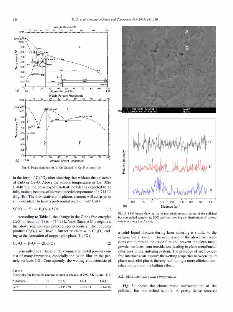
Fig. 4. Phase diagrams of (a) Cu–Sn and (b) Cu–P systems [16].
n the form of CuPO3 after sintering, but without the existencef CuO or Cu2O. Above the solidus temperature of Cu–10Sn∼840 ◦C), the pre-alloyed Cu–8.4P powder is expected to beully molten, because of a lower eutectic temperature of ∼714 ◦CFig. 4b). The dissociative phosphorus element will act as an initu deoxidizer to have a preferential reaction with CuO:
CuO + 2P = P2O5 + 5Cu (1)
According to Table 1, the change in the Gibbs free energies�G) of reaction (1) is −714.23 kJ/mol. Since �G is negative,he above reaction can proceed spontaneously. The reducingroduct (P2O5) will have a further reaction with Cu2O, lead-ng to the formation of copper phosphate (CuPO3):
u2O + P2O5 = 2CuPO3 (2)
Generally, the surfaces of the commercial metal powder con-ist of many impurities, especially the oxide film on the par-icle surfaces [18]. Consequently, the wetting characteristic of
able 1he Gibbs free formation energies of pure substances at 298.15 K (kJ/mol) [17]
ubstance P Cu P2O5 CuO Cu2O
Gf 0 0 −1355.68 −128.29 −147.88
pifps
3
p
ig. 5. SEM image showing the characteristic microstructure of the polishedut non-etched sample (a); EDX analyses showing the distributions of variouslements along line AB (b).
solid–liquid mixture during laser sintering is similar to theeramic/metal system. The occurrence of the above two reac-ions can eliminate the oxide film and prevent the clean metalowder surfaces from reoxidation, leading to clean metal/metalnterfaces in the sintering system. The presence of such oxide-ree interfaces can improve the wetting properties between liquidhase and solid phase, thereby facilitating a more efficient den-ification without the balling effect.
.2. Microstructure and composition
Fig. 5a shows the characteristic microstructure of theolished but non-etched sample. A pretty dense sintered

nd Compounds 438 (2007) 184–189 187
sccAeebaptbssadC51asbpPd
Fig. 6. SEM image showing the characteristic microstructure of the etched sam-
D. Gu et al. / Journal of Alloys a
tructure surrounded with dark networks (grain boundaries)an be observed. Fig. 5b shows the EDX line scan resultsoncerning the distributions of various elements along lineB in Fig. 5a. It is clear that the distributions of Cu and Sn
lements show a relatively slight change. The distribution of Plement, interestingly, shows a significant fluctuation at grainoundaries. During laser sintering, the binder Cu–10Sn and thedditive Cu–8.4P, generally, melt completely to form the liquidhase. The Cu powder, due to the relatively higher meltingemperature, dissolves slightly in the wetting liquid. As the laseream moves away, the solid–liquid mixture undergoes a rapidolidification process. The high temperature phase �-Cu firstlytarts to solidify. Due to a relatively high mutual solubility of Snnd Cu (∼11 wt.% at 350 ◦C) (Fig. 4a), a relatively homogenousistribution of the Sn element in the Cu matrix in the form of �-uSn solid solution is obtained after solidification (Figs. 3 andb). However, because of a low solubility of P in Cu (less thanwt.% at 350 ◦C) (Fig. 4b), the P element tends to be pushedway from the Cu phase and, subsequently, segregates along theolidified phase, resulting in a high concentration along grain
oundaries. On the other hand, since the thermal cycle in DMLSrocess is extremely short, the time for the homogenizing of thein the Cu matrix is too short, thereby causing the non-uniformistribution of the P element in the sintered structure (Fig. 5b).
p
Fig. 7. EDX analyses showing chemical compositions in
le.
Zone A (a), Zone B (b), and Zone C (c) in Fig. 6.

1 nd Compounds 438 (2007) 184–189
stdEsTwscCmsott
Table 2Mechanical properties of the laser sintered sample
Property Measured value
Relative density (%) 94.6Fracture strength (MPa) 169.2H
swa
88 D. Gu et al. / Journal of Alloys a
Fig. 6 shows the characteristic microstructure of the etchedample. Fig. 7 depicts the chemical compositions measured inhe various zones in Fig. 6. It is clear that a continuous network ofendrites was formed after sintering. Combined with XRD andDX results (Figs. 3 and 7b), it is reasonable to conclude thatuch dendrites (Zone B in Fig. 6) were �-CuSn solid solution.he structure surrounded by the dendrites (Zone A in Fig. 6)as consisted of a unique element Cu (Fig. 7a). Thus, the laser
intering mechanism of this multi-component powder systeman be well explained as follows. In DMLS process, the binderuSn melts and penetrates into the voids between the structuraletal Cu, thereby surrounding and wetting the Cu particles. The
olid particles undergo a rapid arrangement under the actionf capillary forces exerted on them by the wetting liquid. Ashe liquid phase precipitates again in the dendrite morphology,he solids are bonded together to realize a densification of the
Fat(
Fig. 8. SEM images showing the typical fracture surface of the laser sin
ardness (HB) 101.7
intering system. Furthermore, Fig. 7c shows that the P elementas presented at grain boundaries (Zone C in Fig. 6), which is in
ccordance with the experimental results shown in Fig. 5. Also,
ig. 7c reveals the segregation of the oxygen towards the P-richreas. This is because the phosphorus acts as an in situ sink forhe oxygen during sintering, as indicated by reactions (1) and2) in Section 3.1.tered sample (a); local magnifications of Zones A and B (b and c).

nd C
sdwCmsrffatcaDlwprastttslefiltrsdilpicl
4
gCaimato
tpbasbeo
A
taASsafa
R
[
[[[
[[[
[
[[
D. Gu et al. / Journal of Alloys a
Table 2 lists the mechanical properties of the laser sinteredample. It is reasonable to conclude that the DMLS processemonstrates a great promise to manufacture metal componentsith basic properties equivalent to conventionally processedu-based materials [19]. Fig. 8 shows the characteristicicrostructure of the fracture surface of the laser sintered
ample. Metallographic study at a relatively low magnificationeveals the presence of diverse types of fracture (Fig. 8a). Theracture surface was mainly characterized by a ductile type ofracture, since a number of dimples were generally observed inmajority of areas (similar to Zone A in Fig. 8a) (Fig. 8b). Fur-
hermore, a small fraction of areas (similar to Zone B in Fig. 8a)learly exhibited the debonding along phase (or particle) bound-ries, showing a typical intercrystalline fracture (Fig. 8c). SinceMLS is a layer-by-layer additive process, oxidation of the
aser-processed powder is a severe impediment to liquid–solidettability and, accordingly, causes delamination induced byoor interlayer bonding [6,20]. In the present study, the chemicaleactions between phosphorus and oxygen, as mentioned above,llow the formation of phosphorous-based phases. Since theseubstances are generally lighter than the liquid metal, they tendo float on the top of the melt under the action of localized massransfer within the molten pool [18,21]. After solidification,he phosphorous-based substances cover the surface of theintered layer, thereby forming a protective film between theaser-processed materials and the ambient atmosphere. Theffective protection of such film prevents the sintered layerrom oxidation and, thus, ensures good wetting and coherentnterlayer consolidation during laser sintering of the subsequentayer, leading to the presence of the strong ductile and intercrys-alline types of fracture (Fig. 8b and c). However, Fig. 8b alsoeveals the formation of a small amount of pores on the fractureurface. In DMLS process, the laser beam scans over the pow-er bed in a line-by-line fashion and the duration of the laserrradiation at any powder particles is extremely short (typicallyess than 4 ms) [22]. The rapid and localized nature of DMLSrevents the sufficient removal and diffusion of the liquid phasen certain laser-irradiated areas, hence weakening the bondingoherence of the structural metal by the liquid and, accordingly,eaving some pores in the sintered structure (Fig. 8b).
. Conclusions
We have performed a detailed investigation into the metallur-ical mechanisms in direct laser sintering of a multi-componentu-based metal powder consisting of a mixture of Cu, Cu–10Sn,nd Cu–8.4P. The liquid phase sintering with the complete melt-ng of the binder CuSn and the non-melting of the structural
etal Cu acts as a feasible mechanism of laser sintering. Thedditive phosphorus element can act as an in situ deoxidizero prevent the sintering system from oxidation by formationf P2O5 and CuPO3, thereby improving the liquid–solid wet-
[[
[
ompounds 438 (2007) 184–189 189
ing characteristics and the resultant sintered densification. Thehosphorus element shows a high concentration along grainoundaries, due to a low mutual solubility of P and Cu as wells the short thermal cycle during laser sintering. The fractureurface of the laser sintered sample is primarily characterizedy a strong ductile type of fracture, which is attributed to thefficient protection of phosphorus element against the interlayerxidation.
cknowledgements
The authors would like to thank the financial support fromhe Joint Fund of National Natural Science Foundation of Chinand China Academy of Engineering Physics (10276017), theeronautical Science Foundation of China (04H52061), and thecientific Research Innovations Foundation of Nanjing Univer-ity of Aeronautics and Astronautics (S0403-061). One of theuthors (Dongdong Gu) gratefully acknowledges the supportrom the Graduate School, Nanjing University of Aeronauticsnd Astronautics.
eferences
[1] D.D. Gu, Y.F. Shen, P. Dai, M.C. Yang, Trans. Nonferrous Met. Soc. China16 (2006) 357–362.
[2] A. Simchi, H. Pohl, Mater. Sci. Eng. A 383 (2004) 191–200.[3] H.H. Zhu, L. Lu, J.Y.H. Fuh, Mater. Sci. Eng. A 371 (2004) 170–177.[4] Y. Wang, J. Bergstrom, C. Burman, J. Mater. Process. Technol. 172 (2006)
77–87.[5] S. Das, J.J. Beaman, M. Wohlert, D.L. Bourell, Rapid Prototyping J. 4
(1998) 112–117.[6] S. Das, Adv. Eng. Mater. 5 (2003) 701–711.[7] D.D. Gu, Y.F. Shen, J. Alloys Compd. 431 (2007) 112–120.[8] A. Simchi, F. Petzoldt, H. Pohl, J. Mater. Process. Technol. 141 (2003)
319–328.[9] Y. Tang, H.T. Loh, Y.S. Wong, J.Y.H. Fuh, L. Lu, X. Wang, J. Mater. Process.
Technol. 140 (2003) 368–372.10] J.P. Kruth, P. Mercelis, J. Van Vaerenbergh, L. Froyen, M. Rombouts, Rapid
Prototyping J. 11 (2005) 26–36.11] D. Uzunsoy, I.T.H. Chang, P. Bowen, Powder Metall. 45 (2002) 251–254.12] Y.F. Shen, D.D. Gu, Y.F. Pan, Key Eng. Mater. 315–316 (2006) 357–360.13] H.H. Zhu, L. Lu, J.Y.H. Fuh, Proc. Inst. Mech. Eng., Part B: J. Eng. Manuf.
220 (2006) 183–190.14] H. Asgharzadeh, A. Simchi, Mater. Sci. Eng. A 403 (2005) 290–298.15] D.D. Gu, Y.F. Shen, J. Alloys Compd. 432 (2007) 163–166.16] T.B. Massalski, Binary Alloy Phase Diagrams, second ed., ASM Interna-
tional, Materials Park, Ohio, 1996.17] I. Barin, Thermochemical Data of Pure Substances, third ed., VCH, New
York, 1993.18] H.H. Zhu, L. Lu, J.Y.H. Fuh, C.C. Wu, Mater. Des. 27 (2006) 166–170.19] K.H. Matucha, Materials: Science and Technology: A Comprehensive
Treatment, in: R.W. Cahn, P. Haasen, E.J. Kramer (Eds.), Structure andProperties of Nonferrous Alloys, vol. 8, VCH, New York, 1996, pp.
302–303.20] D.D. Gu, Y.F. Shen, Mater. Sci. Eng. A 435–436 (2006) 54–61.21] X. Zou, Braze Welding, first ed., China Machine Press, Beijing, 1989 (in
Chinese).22] A. Simchi, H. Pohl, Mater. Sci. Eng. A 359 (2003) 119–128.