Metallurgical Failure Analysis of a Fractured CGA No. … Failure Analysis of a Fractured CGA No....
33
Shipping Address: 9301 Innovation Drive, Suite 175 Daleville, IN 47334 Telephone 765-378-4102 Fax 765-378-4108 Mailing Address: PO Box 569 Daleville, IN 47334-0569 Phone: 800-874-3563 LABORATORY REPORT Report Number: D11011038 Report Date: 1/27/2011 Attn: Jason Wilkerson A. L. Lee Corporation P.O. Box 99 Lester, WV 25865 PO Number: 11799 Metallurgical Failure Analysis of a Fractured CGA No. 701 Oxygen Fitting Test results relate only to the items tested. This document shall not be reproduced, except in full, without the written approval of Sherry Laboratories, Inc. A2LA accredited for Chemical and Mechanical Testing: Certificates #0174-01 & 0174-02. Nadcap accredited Materials Testing Laboratory. The recording of false, fictitious, or fraudulent statements or entries on this document may be a punishable offense under federal and state law. When applicable, measurement uncertainty estimates are available upon request. Page 1 of 33 Background Nine (9) CGA No. 701 Fittings, one (1) new condition Nut, and two (2) inspection fluids were submitted due to fracture of one of the Fittings of Underground Rescue Chamber Serial No. LS9031. For tracking purposes Sherry Laboratories assigned each sample a unique identifier, as shown in Table 1. The incident Chamber S/N LS9031 had been in service in a coal mine for approximately 2-1/2 to 3 years. The Chamber Fittings were originally reported as having been exposed to the “Sherlock” inspection fluid which was thought to contain ammonia. Subsequent investigation by the client indicated that neither inspection fluid was likely to contain ammoniacal compounds. Table 1. Fitting* Identification Rescue Chamber Serial No. (Unit No.) Sherry Laboratories Identifier Comments Inspection Fluid Exposure Fitting A Incident Fitting with Fractured Nut LS9031 (Unit No. 59) Fittings B through G Intact Fittings Fluid K: Sherlock Fluid L: Snoop LS10124 (Unit No. 159) Fittings I and J Intact Fittings Fluid L: Snoop Exemplar Product Nut H New Condition None Exemplar Product Fluid K “Sherlock” manufactured by Winton Products Co., Inc. Exemplar Product Fluid L “Snoop” manufactured by Swagelock Manufacturing Company *Compressed Gas Association, Inc. Connection No. 701 (CGA V-1-October 1994)
Transcript of Metallurgical Failure Analysis of a Fractured CGA No. … Failure Analysis of a Fractured CGA No....

Shipping Address: 9301 Innovation Drive, Suite 175 Daleville, IN 47334 Telephone 765-378-4102 Fax 765-378-4108
Mailing Address: PO Box 569
Daleville, IN 47334-0569 Phone: 800-874-3563
LABORATORY REPORT
Report Number: D11011038Report Date: 1/27/2011
Attn: Jason Wilkerson A. L. Lee Corporation P.O. Box 99 Lester, WV 25865 PO Number: 11799
Metallurgical Failure Analysis of a Fractured CGA No. 701 Oxygen Fitting
Test results relate only to the items tested. This document shall not be reproduced, except in full, without the written approval of Sherry Laboratories, Inc. A2LA accredited for Chemical and Mechanical Testing: Certificates #0174-01 & 0174-02. Nadcap accredited Materials Testing Laboratory. The recording of false, fictitious, or fraudulent statements or entries on this document may be a punishable offense under federal and state law. When applicable, measurement uncertainty estimates are available upon request.
Page 1 of 33
Background Nine (9) CGA No. 701 Fittings, one (1) new condition Nut, and two (2) inspection fluids were submitted due to fracture of one of the Fittings of Underground Rescue Chamber Serial No. LS9031. For tracking purposes Sherry Laboratories assigned each sample a unique identifier, as shown in Table 1. The incident Chamber S/N LS9031 had been in service in a coal mine for approximately 2-1/2 to 3 years. The Chamber Fittings were originally reported as having been exposed to the “Sherlock” inspection fluid which was thought to contain ammonia. Subsequent investigation by the client indicated that neither inspection fluid was likely to contain ammoniacal compounds.
Table 1. Fitting* Identification
Rescue Chamber Serial No. (Unit No.)
Sherry Laboratories Identifier Comments Inspection Fluid
Exposure
Fitting A Incident Fitting with Fractured Nut LS9031
(Unit No. 59) Fittings B through G Intact Fittings
Fluid K: Sherlock Fluid L: Snoop
LS10124 (Unit No. 159) Fittings I and J Intact Fittings Fluid L: Snoop
Exemplar Product Nut H New Condition None
Exemplar Product Fluid K “Sherlock” manufactured by Winton Products Co., Inc.
Exemplar Product Fluid L “Snoop” manufactured by Swagelock Manufacturing Company
*Compressed Gas Association, Inc. Connection No. 701 (CGA V-1-October 1994)
D11011038 A. L. Lee Corporation
1/27/2011
Test results relate only to the items tested. This document shall not be reproduced, except in full, without the written approval of Sherry Laboratories, Inc. A2LA accredited for Chemical and Mechanical Testing: Certificates #0174-01 & 0174-02. Nadcap accredited Materials Testing Laboratory. The recording of false, fictitious, or fraudulent statements or entries on this document may be a punishable offense under federal and state law. When applicable, measurement uncertainty estimates are available upon request.
Page 2 of 33
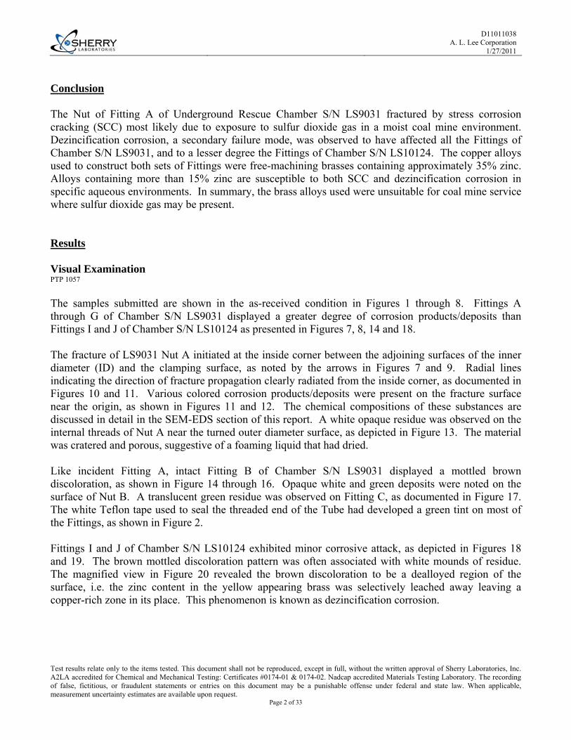
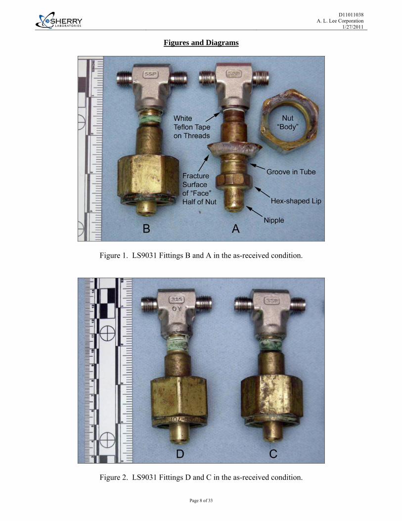
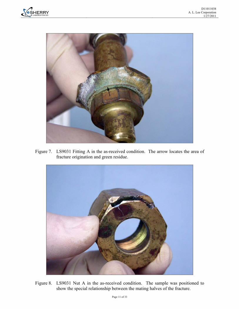
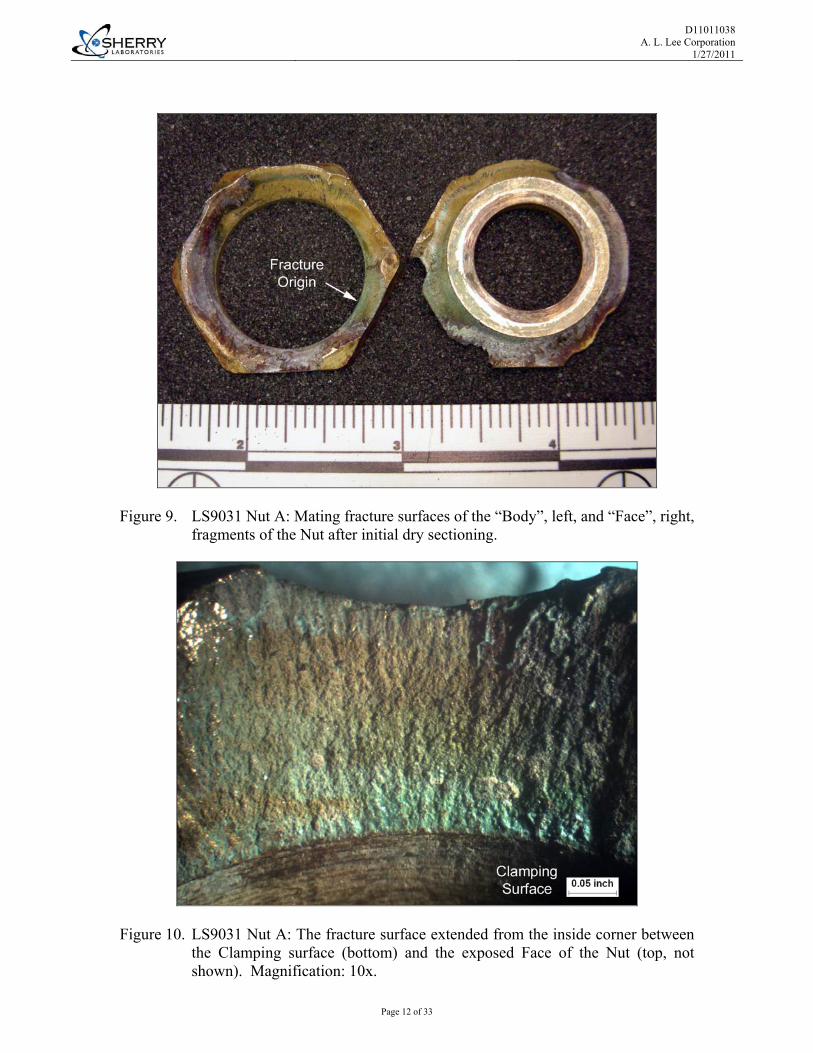
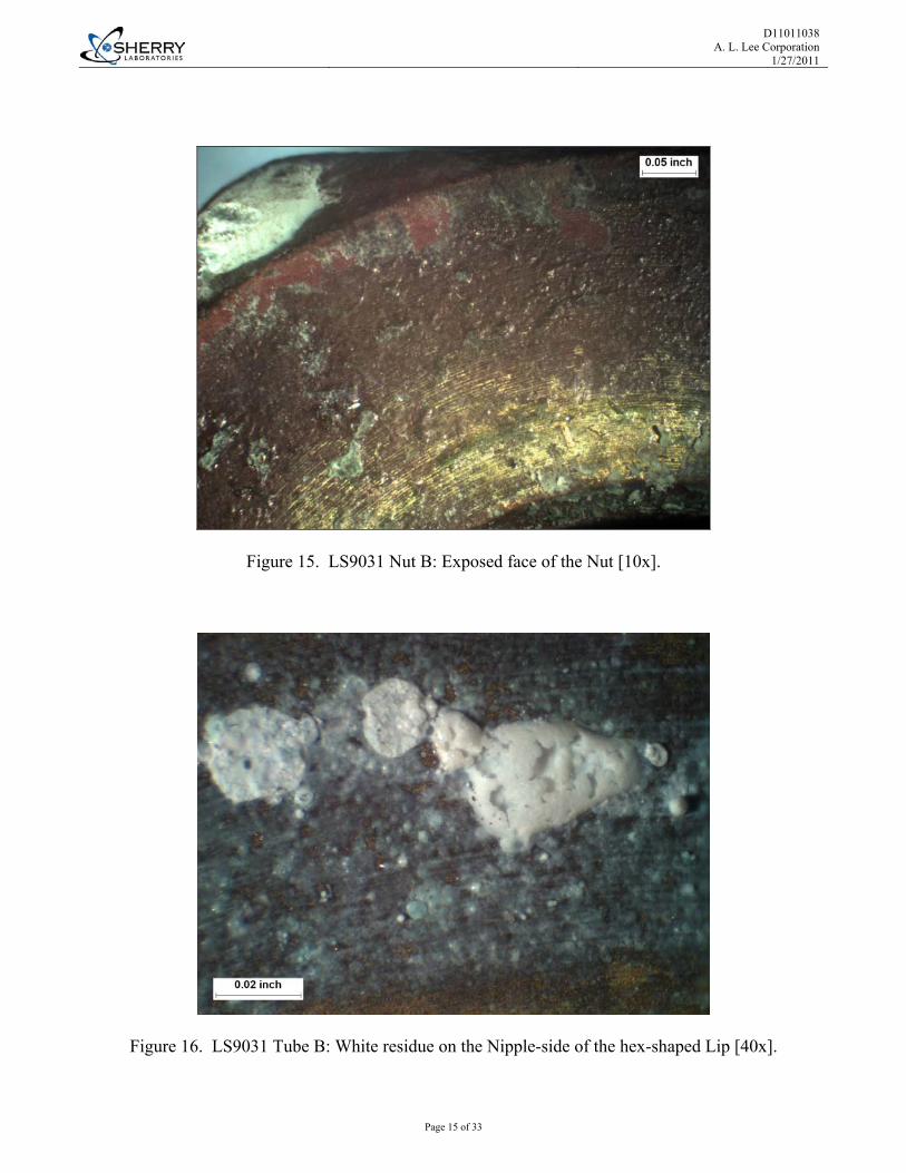
Conclusion The Nut of Fitting A of Underground Rescue Chamber S/N LS9031 fractured by stress corrosion cracking (SCC) most likely due to exposure to sulfur dioxide gas in a moist coal mine environment. Dezincification corrosion, a secondary failure mode, was observed to have affected all the Fittings of Chamber S/N LS9031, and to a lesser degree the Fittings of Chamber S/N LS10124. The copper alloys used to construct both sets of Fittings were free-machining brasses containing approximately 35% zinc. Alloys containing more than 15% zinc are susceptible to both SCC and dezincification corrosion in specific aqueous environments. In summary, the brass alloys used were unsuitable for coal mine service where sulfur dioxide gas may be present. Results Visual Examination PTP 1057 The samples submitted are shown in the as-received condition in Figures 1 through 8. Fittings A through G of Chamber S/N LS9031 displayed a greater degree of corrosion products/deposits than Fittings I and J of Chamber S/N LS10124 as presented in Figures 7, 8, 14 and 18. The fracture of LS9031 Nut A initiated at the inside corner between the adjoining surfaces of the inner diameter (ID) and the clamping surface, as noted by the arrows in Figures 7 and 9. Radial lines indicating the direction of fracture propagation clearly radiated from the inside corner, as documented in Figures 10 and 11. Various colored corrosion products/deposits were present on the fracture surface near the origin, as shown in Figures 11 and 12. The chemical compositions of these substances are discussed in detail in the SEM-EDS section of this report. A white opaque residue was observed on the internal threads of Nut A near the turned outer diameter surface, as depicted in Figure 13. The material was cratered and porous, suggestive of a foaming liquid that had dried. Like incident Fitting A, intact Fitting B of Chamber S/N LS9031 displayed a mottled brown discoloration, as shown in Figure 14 through 16. Opaque white and green deposits were noted on the surface of Nut B. A translucent green residue was observed on Fitting C, as documented in Figure 17. The white Teflon tape used to seal the threaded end of the Tube had developed a green tint on most of the Fittings, as shown in Figure 2. Fittings I and J of Chamber S/N LS10124 exhibited minor corrosive attack, as depicted in Figures 18 and 19. The brown mottled discoloration pattern was often associated with white mounds of residue. The magnified view in Figure 20 revealed the brown discoloration to be a dealloyed region of the surface, i.e. the zinc content in the yellow appearing brass was selectively leached away leaving a copper-rich zone in its place. This phenomenon is known as dezincification corrosion.

D11011038 A. L. Lee Corporation
1/27/2011
Test results relate only to the items tested. This document shall not be reproduced, except in full, without the written approval of Sherry Laboratories, Inc. A2LA accredited for Chemical and Mechanical Testing: Certificates #0174-01 & 0174-02. Nadcap accredited Materials Testing Laboratory. The recording of false, fictitious, or fraudulent statements or entries on this document may be a punishable offense under federal and state law. When applicable, measurement uncertainty estimates are available upon request.
Page 3 of 33
Chemical Analysis X-Ray Fluorescence Spectroscopy (XRF), ASTM E 1621-05 / CTP3093 The chemical compositions of selected components of Chamber S/N LS9031 were consistent with Copper Alloy UNS C36000 free-machining brass, as shown in Table 2. The requirements of ASTM B16/B16M-05 were provided for reference purposes only as no standard was specified.
Table 2. Metals Chemistry Results (Wt %)
Element LS9031 Nut A
Results
LS9031 Nut B
Results
LS9031 Tube A Results
ASTM B 16/ B 16M-05 Method, ASTM
Copper 61.9 62.1 62.4 60.0 - 63.0 By Difference
Lead 2.7 2.9 2.5 2.5 - 3.7 ASTM E1621-05/CTP 3093/XRF
Iron 0.18 0.17 0.18 0.35 Max. ASTM E1621-05/CTP 3093/XRF
Zinc 34.99 (Balance)
34.68 (Balance)
34.69 (Balance) Balance ASTM E1621-05/CTP
3093/XRF
Nickel 0.05 0.05 0.05 Not Specified ASTM E1621-05/CTP 3093/XRF
Tin 0.14 0.15 0.14 Not Specified ASTM E1621-05/CTP 3093/XRF
Silver <0.01 <0.01 <0.01 Not Specified ASTM E1621-05/CTP 3093/XRF
Aluminum <0.01 <0.01 <0.01 Not Specified ASTM E1621-05/CTP 3093/XRF
Cobalt <0.05 <0.05 <0.05 Not Specified ASTM E1621-05/CTP 3093/XRF
Chromium <0.05 <0.05 <0.05 Not Specified ASTM E1621-05/CTP 3093/XRF
Manganese <0.05 <0.05 <0.05 Not Specified ASTM E1621-05/CTP 3093/XRF
Phosphorus <0.01 <0.01 <0.01 Not Specified ASTM E1621-05/CTP 3093/XRF
Antimony <0.05 <0.05 <0.05 Not Specified ASTM E1621-05/CTP 3093/XRF
Silicon <0.05 <0.05 <0.05 Not Specified ASTM E1621-05/CTP 3093/XRF
Copper + Sum of Named Elements >99.5 >99.5 >99.5 Not Specified Calculation

D11011038 A. L. Lee Corporation
1/27/2011
Test results relate only to the items tested. This document shall not be reproduced, except in full, without the written approval of Sherry Laboratories, Inc. A2LA accredited for Chemical and Mechanical Testing: Certificates #0174-01 & 0174-02. Nadcap accredited Materials Testing Laboratory. The recording of false, fictitious, or fraudulent statements or entries on this document may be a punishable offense under federal and state law. When applicable, measurement uncertainty estimates are available upon request.
Page 4 of 33
Chemical Analysis (Continued) The chemical composition of the Nut I of Chamber S/N LS10124 was consistent with Copper Alloy UNS C35340 free-machining brass, while the composition of the Exemplar Nut H met the requirements of UNS C36000 free-machining brass, as shown in Table 3. The requirements of ASTM B16/B16M-05 were provided for reference.
Table 3. Metals Chemistry Results (Wt %)
Element LS10124
Nut I Results
New Cond.Nut H Results
ASTM B 16/ B 16M-05 Method, ASTM
Copper 62.3 61.0 60.0 - 63.0 By Difference
Lead 2.0 3.5 2.5 - 3.7 ASTM E1621-05/CTP 3093/XRF
Iron 0.18 0.15 0.35 Max. ASTM E1621-05/CTP 3093/XRF
Zinc 35.34 (Balance)
35.11 (Balance) Balance ASTM E1621-05/CTP
3093/XRF
Nickel 0.05 <0.05 Not Specified ASTM E1621-05/CTP 3093/XRF
Tin 0.14 0.17 Not Specified ASTM E1621-05/CTP 3093/XRF
Silver <0.01 <0.01 Not Specified ASTM E1621-05/CTP 3093/XRF
Aluminum <0.01 <0.01 Not Specified ASTM E1621-05/CTP 3093/XRF
Cobalt <0.05 <0.05 Not Specified ASTM E1621-05/CTP 3093/XRF
Chromium <0.05 <0.05 Not Specified ASTM E1621-05/CTP 3093/XRF
Manganese <0.05 <0.05 Not Specified ASTM E1621-05/CTP 3093/XRF
Phosphorus <0.01 <0.01 Not Specified ASTM E1621-05/CTP 3093/XRF
Antimony <0.05 <0.05 Not Specified ASTM E1621-05/CTP 3093/XRF
Silicon <0.05 <0.05 Not Specified ASTM E1621-05/CTP 3093/XRF
Copper + Sum of Named Elements >99.5 >99.5 Not Specified Calculation

D11011038 A. L. Lee Corporation
1/27/2011
Test results relate only to the items tested. This document shall not be reproduced, except in full, without the written approval of Sherry Laboratories, Inc. A2LA accredited for Chemical and Mechanical Testing: Certificates #0174-01 & 0174-02. Nadcap accredited Materials Testing Laboratory. The recording of false, fictitious, or fraudulent statements or entries on this document may be a punishable offense under federal and state law. When applicable, measurement uncertainty estimates are available upon request.
Page 5 of 33
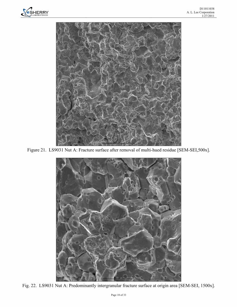
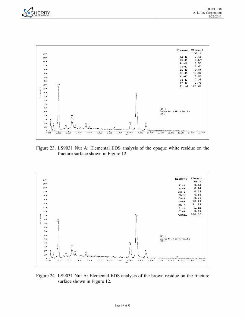
Scanning Electron Microscopy / Microanalysis Scanning Electron Microscopy (SEM), PTP-1066, JEOL, JSM T330A Energy Dispersive Spectroscopy (EDS), ASTM E 1508-98 (2008) The fracture surface in the origin location was cleaned of corrosion products for subsequent examination by Scanning Electron Microscopy (SEM). The brittle fracture surface of LS9031 Nut A was predominantly intergranular and typical of a stress corrosion crack (SCC) in brass, as shown in Figures 21 and 22. Individual grains of the fracture surface were pock marked with minute corrosion pits that formed after the crack initiated. Prior to cleaning the fracture surface for examination, the various colored residues were chemically analyzed by standardless Energy Dispersive X-ray Spectroscopy (EDS) in conjunction with SEM. Reference Figure 12. In the EDS spectra acquired, the light elements carbon (C) and oxygen (O) may have been detected, but were not quantified. The colored residues on the fracture surface of LS9031 Nut A shared many elements in common, as documented in Figures 23 through 28. The different colors were reflective of variations in chemical composition and thickness. Chlorine (Cl), most likely in the form of chlorides, was present in all of the residues at low levels. The presence of chlorides can result in the formation of acidic species that promote corrosion, e.g. dezincification. The white Teflon Tape that sealed the threads on Tube C, was tinted green, as seen in Figure 2. EDS analysis detected fluorine (F), an element native to the fluoropolymer tape, and other elements common to the various colored residues of Nut A, as documented in Figure 33. The elements detected indicate the transport of corrosion products to the tape surface. EDS analysis of other residues obtained from Nut A (Figure 29), Fitting B (Figure 30 and 31), and Fitting C (Figure 32) likewise detected the common elements. In addition, carbon (C), oxygen (O), and sulfur (S) were universally detected in all of these analyses. This was not surprising as these elements were the major constituents of both inspection fluids K and L, as documented in Figures 36 and 37. The white residue mounds on LS10124 Fitting I and the adjoining brown areas contained fewer of the elements common to the components of Chamber S/N LS9031, as illustrated in Figure 34 and 35. However, chlorine, in the form of chlorides, was associated with the brown discolorations suggesting its active part in dezincification corrosion. Note: SEM/EDS analysis is a semi-quantitative method of detecting elements with atomic number five (boron (B)) and greater that are present in minimum quantities of approximately 0.5%. The error associated with the Proza/ZAF corrections have not yet been established for this system, however errors on the order of 1 – 5% could be encountered. The error associated with standardless analyses can be substantially higher (on the order of 20% in some cases).
D11011038 A. L. Lee Corporation
1/27/2011
Test results relate only to the items tested. This document shall not be reproduced, except in full, without the written approval of Sherry Laboratories, Inc. A2LA accredited for Chemical and Mechanical Testing: Certificates #0174-01 & 0174-02. Nadcap accredited Materials Testing Laboratory. The recording of false, fictitious, or fraudulent statements or entries on this document may be a punishable offense under federal and state law. When applicable, measurement uncertainty estimates are available upon request.
Page 6 of 33
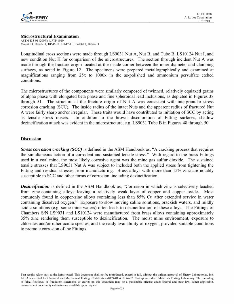
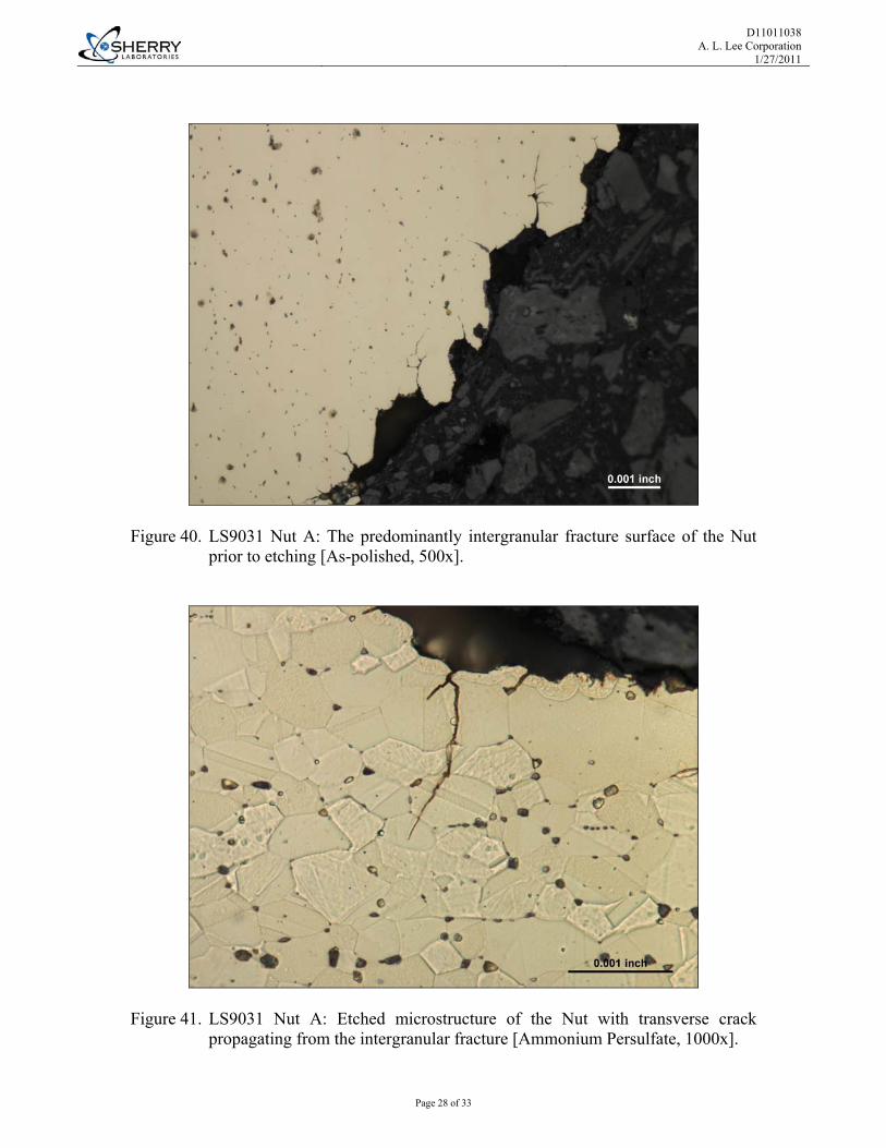
Microstructural Examination ASTM E 3-01 (2007)ε1, PTP 1010 Mount ID: 10645-11, 10646-11, 10647-11, 10648-11, 10649-11 Longitudinal cross sections were made through LS9031 Nut A, Nut B, and Tube B, LS10124 Nut I, and new condition Nut H for comparison of the microstructures. The section through incident Nut A was made through the fracture origin located at the inside corner between the inner diameter and clamping surfaces, as noted in Figure 12. The specimens were prepared metallographically and examined at magnifications ranging from 25x to 1000x in the as-polished and ammonium persulfate etched conditions. The microstructures of the components were similarly composed of twinned, relatively equiaxed grains of alpha phase with elongated beta phase and fine spheroidal lead inclusions, as depicted in Figures 38 through 51. The structure at the fracture origin of Nut A was consistent with intergranular stress corrosion cracking (SCC). The inside radius of the intact Nuts and the apparent radius of fractured Nut A were fairly sharp and/or irregular. These traits would have contributed to initiation of SCC by acting as tensile stress raisers. In addition to the brown discoloration of Fitting surfaces, shallow dezincification attack was evident in the microstructure, e.g. LS9031 Tube B in Figures 48 through 50. Discussion Stress corrosion cracking (SCC) is defined in the ASM Handbook as, “A cracking process that requires the simultaneous action of a corrodent and sustained tensile stress.” With regard to the brass Fittings used in a coal mine, the most likely corrosive agent was the mine gas sulfur dioxide. The sustained tensile stresses that LS9031 Nut A was subject to included both the applied stress from tightening the Fitting and residual stresses from manufacturing. Brass alloys with more than 15% zinc are notably susceptible to SCC and other forms of corrosion, including dezincification. Dezincification is defined in the ASM Handbook as, “Corrosion in which zinc is selectively leached from zinc-containing alloys leaving a relatively weak layer of copper and copper oxide. Most commonly found in copper-zinc alloys containing less than 85% Cu after extended service in water containing dissolved oxygen.” Exposure to slow moving saline solutions, brackish waters, and mildly acidic solutions (e.g. some mine waters) often leads to dezincification of these alloys. The Fittings of Chambers S/N LS9031 and LS10124 were manufactured from brass alloys containing approximately 35% zinc rendering them susceptible to dezincification. The moist mine environment, exposure to chlorides and/or other acidic species, and the ready availability of oxygen, provided suitable conditions to promote corrosion of the Fittings.

D11011038 A. L. Lee Corporation
1/27/2011
Test results relate only to the items tested. This document shall not be reproduced, except in full, without the written approval of Sherry Laboratories, Inc. A2LA accredited for Chemical and Mechanical Testing: Certificates #0174-01 & 0174-02. Nadcap accredited Materials Testing Laboratory. The recording of false, fictitious, or fraudulent statements or entries on this document may be a punishable offense under federal and state law. When applicable, measurement uncertainty estimates are available upon request.
Page 7 of 33
Mounts and remnants will be returned via common carrier. Sherry Laboratories reserves the right to invoice for any subsequent services, including but not limited to testing or consulting, in support of this failure investigation.
Approved by: __________________________ David C. Mohr, CWI Metallurgist / Failure Analyst
D11011038 A. L. Lee Corporation
1/27/2011
Page 8 of 33
Figures and Diagrams
Figure 1. LS9031 Fittings B and A in the as-received condition.
Figure 2. LS9031 Fittings D and C in the as-received condition.

D11011038 A. L. Lee Corporation
1/27/2011
Page 9 of 33
Figure 3. LS9031 Fittings E, F and G in the as-received condition.
Figure 4. New Nut H in the as-received condition.

D11011038 A. L. Lee Corporation
1/27/2011
Page 10 of 33
Figure 5. LS10124 Fittings I and J in the as-received condition.
Figure 6. Fluid Samples K and L in the as-received condition.
D11011038 A. L. Lee Corporation
1/27/2011
Page 11 of 33
Figure 7. LS9031 Fitting A in the as-received condition. The arrow locates the area of fracture origination and green residue.
Figure 8. LS9031 Nut A in the as-received condition. The sample was positioned to show the special relationship between the mating halves of the fracture.
D11011038 A. L. Lee Corporation
1/27/2011
Page 12 of 33
Figure 9. LS9031 Nut A: Mating fracture surfaces of the “Body”, left, and “Face”, right, fragments of the Nut after initial dry sectioning.
Figure 10. LS9031 Nut A: The fracture surface extended from the inside corner between the Clamping surface (bottom) and the exposed Face of the Nut (top, not shown). Magnification: 10x.

D11011038 A. L. Lee Corporation
1/27/2011
Page 13 of 33
Figure 11. LS9031 Nut A: The area of fracture I was located at the inside corner formed between the clamping surface (bottom) and the inner diameter (ID) surface. Magnification: 30x.
Figure 12. LS9031 Nut A: Various color residues on the fracture surface. The right side surface of the specimen represents the longitudinal metallographic cross section made through the fracture origin [10x].

D11011038 A. L. Lee Corporation
1/27/2011
Page 14 of 33
Figure 13. LS9031 Nut A: White “foam” residue on thread flanks near the machined outer diameter of the Nut [70x].
Figure 14. LS9031 Fitting B after initial dry sectioning.
D11011038 A. L. Lee Corporation
1/27/2011
Page 15 of 33
Figure 15. LS9031 Nut B: Exposed face of the Nut [10x].
Figure 16. LS9031 Tube B: White residue on the Nipple-side of the hex-shaped Lip [40x].
D11011038 A. L. Lee Corporation
1/27/2011
Page 16 of 33
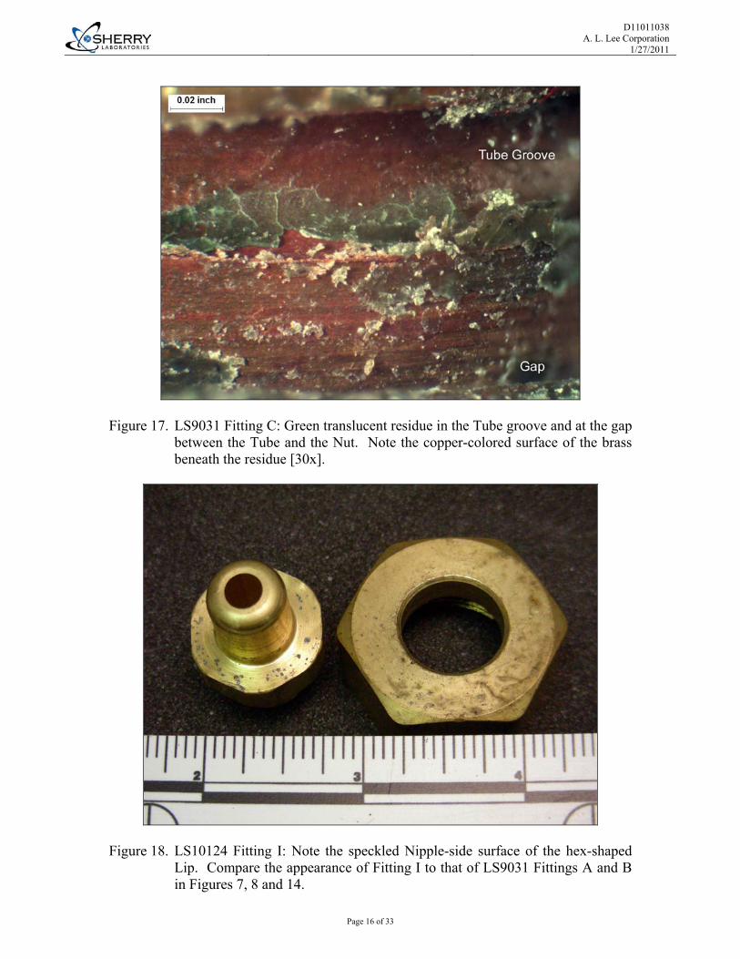
Figure 17. LS9031 Fitting C: Green translucent residue in the Tube groove and at the gap between the Tube and the Nut. Note the copper-colored surface of the brass beneath the residue [30x].
Figure 18. LS10124 Fitting I: Note the speckled Nipple-side surface of the hex-shaped Lip. Compare the appearance of Fitting I to that of LS9031 Fittings A and B in Figures 7, 8 and 14.

D11011038 A. L. Lee Corporation
1/27/2011
Page 17 of 33
Figure 19. LS10124 Fitting I: Note the corrosive attack of the Nipple-side surface of the hex-shaped Lip associated with mounds of white residue [10x].
Figure 20. LS10124 Fitting I: The copper-colored surface beneath the mound of residue is typical of dezincification corrosion [70x].
D11011038 A. L. Lee Corporation
1/27/2011
Page 18 of 33
Figure 21. LS9031 Nut A: Fracture surface after removal of multi-hued residue [SEM-SEI,500x].
Fig. 22. LS9031 Nut A: Predominantly intergranular fracture surface at origin area [SEM-SEI, 1500x].
D11011038 A. L. Lee Corporation
1/27/2011
Page 19 of 33
Figure 23. LS9031 Nut A: Elemental EDS analysis of the opaque white residue on the fracture surface shown in Figure 12.
Figure 24. LS9031 Nut A: Elemental EDS analysis of the brown residue on the fracture surface shown in Figure 12.

D11011038 A. L. Lee Corporation
1/27/2011
Page 20 of 33
Figure 25. LS9031 Nut A: Elemental EDS analysis of the green residue on the fracture surface shown in Figure 12.
Figure 26. LS9031 Nut A: Elemental EDS analysis of the blue residue on the fracture surface shown in Figure 12.

D11011038 A. L. Lee Corporation
1/27/2011
Page 21 of 33
Figure 27. LS9031 Nut A: Elemental EDS analysis of the purple residue on the fracture surface shown in Figure 12.
Figure 28. LS9031 Nut A: Elemental EDS analysis of the opaque light green residue on the clamping face adjacent to the fracture origin shown in Figure 12.

D11011038 A. L. Lee Corporation
1/27/2011
Page 22 of 33
Figure 29. LS9031 Nut A: Elemental EDS analysis of the opaque white “foam” residue on the threads shown in Figure 13.
Figure 30. LS9031 Nut B: Elemental EDS analysis of the green residue on the exposed Face of the Nut shown in Figure 15.

D11011038 A. L. Lee Corporation
1/27/2011
Page 23 of 33
Figure 31. LS9031 Nut B: Elemental EDS analysis of the opaque white residue on the Nipple-side surface of the Lip shown in Figure 16.
Figure 32. LS9031 Fitting C: Elemental EDS analysis of the transparent green residue on the exposed surfaces of the Tube and Nut shown in Figure 17.

D11011038 A. L. Lee Corporation
1/27/2011
Page 24 of 33
Figure 33. LS9031 Fitting C: Elemental EDS analysis of the green-tinted surface of the white Teflon tape used to seal the Tube threads shown in Figure 2.
Figure 34. LS10124 Fitting I: Elemental EDS analysis of the opaque white residue mounds on the Nipple-side surface of the Lip shown in Figures 18 through 20.

D11011038 A. L. Lee Corporation
1/27/2011
Page 25 of 33
Figure 35. LS10124 Fitting I: Elemental EDS analysis of a brown to copper-colored discoloration on the Nipple-side surface of the Lip shown in Figures 18 through 20.
Figure 36. Fluid Sample K: Elemental EDS analysis of a dried residue.

D11011038 A. L. Lee Corporation
1/27/2011
Page 26 of 33
Figure 37. Fluid Sample L: Elemental EDS analysis of a dried residue.

D11011038 A. L. Lee Corporation
1/27/2011
Page 27 of 33
Figure 38. LS9031 Nut A: Longitudinal cross section through fracture origin. Shown is the Nut Body half of the fracture [Ammonium Persulfate, 200x].
Figure 39. LS9031 Nut A: Longitudinal cross section through fracture origin. Shown is the Nut Face half of the fracture [Ammonium Persulfate, 200x].
D11011038 A. L. Lee Corporation
1/27/2011
Page 28 of 33
Figure 40. LS9031 Nut A: The predominantly intergranular fracture surface of the Nut prior to etching [As-polished, 500x].
Figure 41. LS9031 Nut A: Etched microstructure of the Nut with transverse crack propagating from the intergranular fracture [Ammonium Persulfate, 1000x].

D11011038 A. L. Lee Corporation
1/27/2011
Page 29 of 33
Figure 42. LS9031 Nut B: Longitudinal cross section through the inside corner adjoining the inner diameter (ID) and clamping surfaces [Ammonium Persulfate, 200x].
Figure 43. LS9031 Nut B: Typical microstructure [Ammonium Persulfate, 500x].

D11011038 A. L. Lee Corporation
1/27/2011
Page 30 of 33
Figure 44. New condition Nut H: Longitudinal cross section through the inside corner between the inner diameter (ID) and clamping surfaces [Ammonium Persulfate, 200x].
Figure 45. New condition Nut H: Typical microstructure [Ammonium Persulfate, 500x].

D11011038 A. L. Lee Corporation
1/27/2011
Page 31 of 33
Figure 46. LS10124 Nut I: Longitudinal cross section through the inside corner between the inner diameter (ID) and clamping surfaces [Ammonium Persulfate, 200x].
Figure 47. LS10124 Nut I: Typical microstructure [Ammonium Persulfate, 500x].

D11011038 A. L. Lee Corporation
1/27/2011
Page 32 of 33
Figure 48. LS9031 Tube B: Longitudinal cross section through the outer diameter (OD) surface exhibiting a porous zone of copper and oxides [As-polished, 1000x].
Figure 49. LS9031 Tube B: Dezincification at a shallow corrosion pit on the outer diameter [As-polished, 1000x].

D11011038 A. L. Lee Corporation
1/27/2011
Page 33 of 33
Figure 50. LS9031 Tube B: A cross section through the Nipple-side surface of the hex-shaped Lip of a region of dezincification revealed porous copper and gray oxides [As-polished, 1000x].
Figure 51. LS9031 Tube B: Typical microstructure [Ammonium Persulfate, 500x].