Metallurgical Analysis of Pitch Change...
19
LAB ATORIES PP I I 1 1 1 I 1 1 1 I 1 I 1 1 I I 1 December 22,2000 Mr. Alejandro Galioto AIG AVIATION 5700 Wilshire Boulevard, Suite 456E Los Angeles, Califomia 90036 RE: Examination of a Castellated Shear Nut and Cotter Pin fiom a Pitch Change Shaft AIG File Number HP00440; SEAL. Job No. 9790 Dear Mr. Galioto: One (1) castellated shear nut and a sheared cotter pin from a pitch change shaft were submitted to SEAL Laboratories for examination. No specifications or background history of the components were supplied. RESULTS VISUAL EXAMINA TION: Figures l(a) and l(b) show the hardware fiom the pitch change shaft received for examination. The condition of the threaded end of the shaft and the sheared cotter pin is shown in Figures 2(a) through 3@). Figures 4(a) through 5(b) show the castellated nut and pieces of the sheared cotter pin. Examination of the nut revealed stripping of the threads and excessive wear at the washer side of the nut. The threaded end of the shaft and the castellated nut were examined in a Scanning Electron Microscope (SEM). Longitudinal cross sections of the nut and the shaft were prepared for metallographc examination. Also, chemical analysis and hardness testing of the base material of the nut and the shaft were performed. Figure 6 shows the locations of various specimens of the castellated nut for further examination. SEM EXAMINA TION: The samples were cleaned in an ultrasonic bath of acetone and examined in a Scanning Electron Microscope (SEM). d: Figures 7(a) through 8 show the threaded end of the shaft and the sheared cotter pin. Examination of the fiacture surfaces of the cotter pin revealed the presence of shear dimples indicative of an overload fracture due to shear loading.
Transcript of Metallurgical Analysis of Pitch Change...
LAB ATORIES PP I I 1 1 1 I 1 1 1 I 1 I 1 1 I I 1
December 22,2000
Mr. Alejandro Galioto AIG AVIATION 5700 Wilshire Boulevard, Suite 456E Los Angeles, Califomia 90036
RE: Examination of a Castellated Shear Nut and Cotter Pin fiom a Pitch Change Shaft AIG File Number HP00440; SEAL. Job No. 9790
Dear Mr. Galioto:
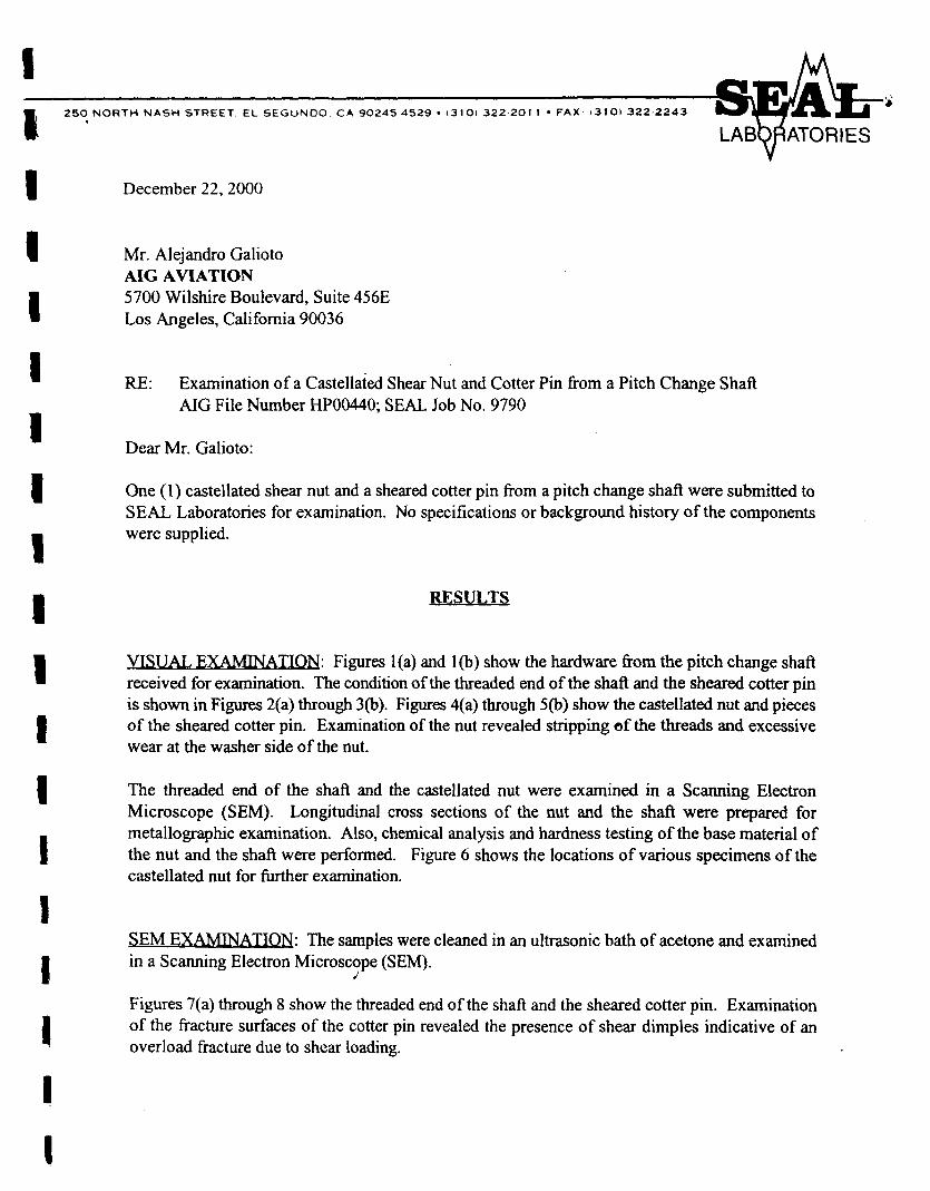
One (1) castellated shear nut and a sheared cotter pin from a pitch change shaft were submitted to SEAL Laboratories for examination. No specifications or background history of the components were supplied.
RESULTS
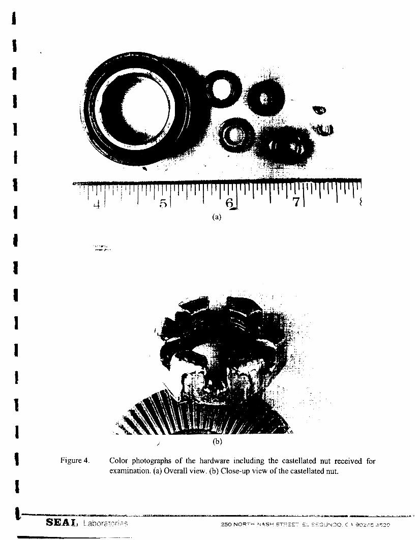
VISUAL EXAMINA TION: Figures l(a) and l(b) show the hardware fiom the pitch change shaft received for examination. The condition of the threaded end of the shaft and the sheared cotter pin is shown in Figures 2(a) through 3@). Figures 4(a) through 5(b) show the castellated nut and pieces of the sheared cotter pin. Examination of the nut revealed stripping of the threads and excessive wear at the washer side of the nut.
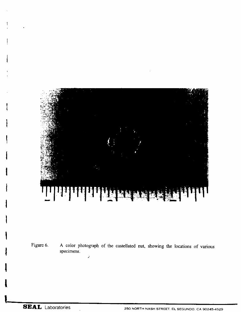
The threaded end of the shaft and the castellated nut were examined in a Scanning Electron Microscope (SEM). Longitudinal cross sections of the nut and the shaft were prepared for metallographc examination. Also, chemical analysis and hardness testing of the base material of the nut and the shaft were performed. Figure 6 shows the locations of various specimens of the castellated nut for further examination.
SEM EXAMINA TION: The samples were cleaned in an ultrasonic bath of acetone and examined in a Scanning Electron Microscope (SEM).
d:
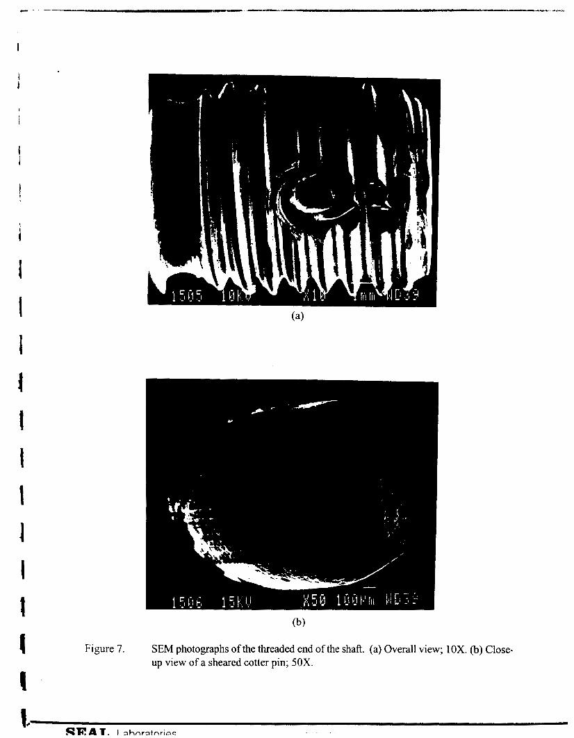
Figures 7(a) through 8 show the threaded end of the shaft and the sheared cotter pin. Examination of the fiacture surfaces of the cotter pin revealed the presence of shear dimples indicative of an overload fracture due to shear loading.
Mr. Alejandro Galioto AIG AVIATION
Page Two
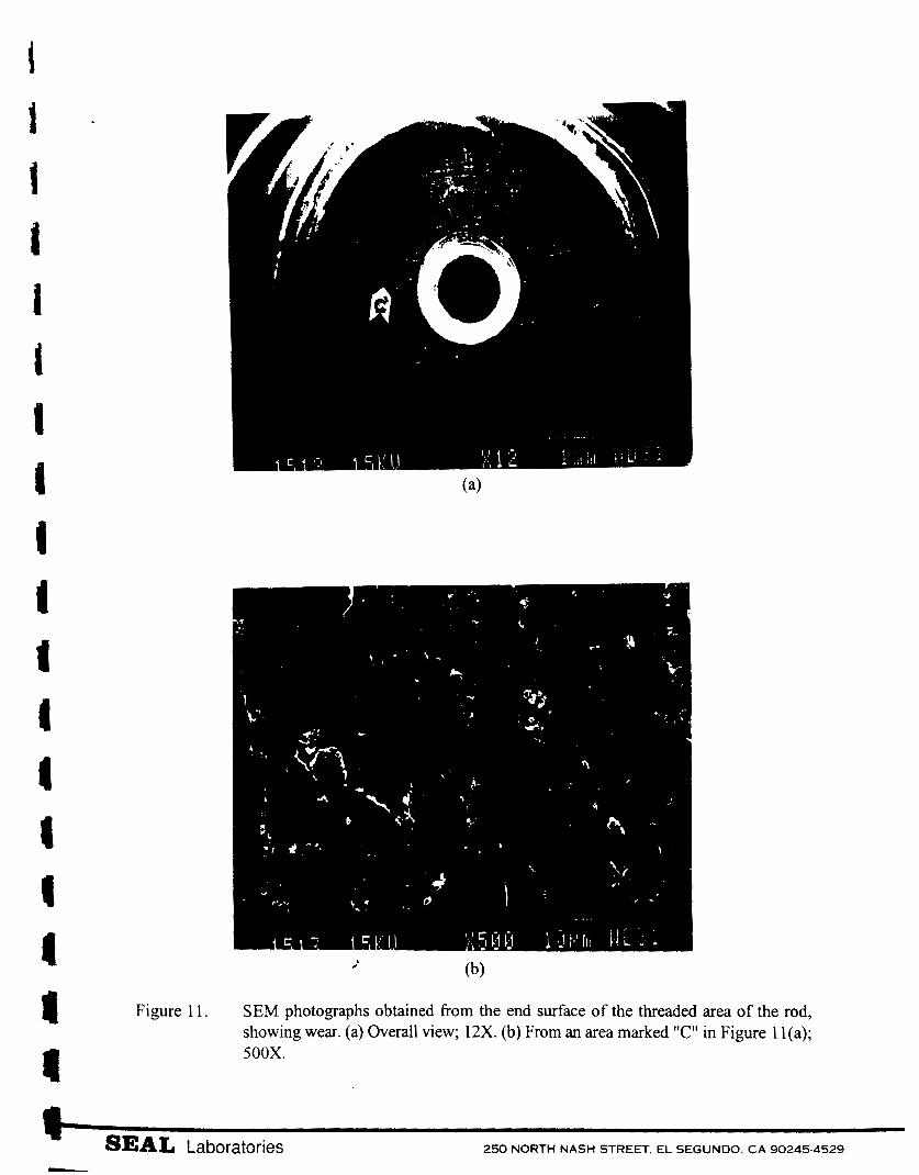
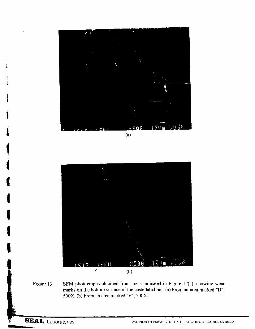
The top of the shaft at the threaded end is shown in Figure 1 l(a). Examination of an area marked "C" in Figure 1 l(a) revealed features of a worn surface; Figure 1 l(b). A circular wear mark was observed on the washer side of the nut; Figures 12(a) and 12(b). Detailed views of the wom surface of the washer side of the nut are shown in Figures 13(a) and 13(b). The size and shape of the circular wear mark were the same as the threaded end of the shaft. These findings suggest that the circular wear mark of the castellated nut was due to rubbing against the end of the shaft.
METALLOGRAP HIC EXAMINATION: The results of metallographic examination are presented in Figures 14(a) through 25(b). The deformation and wear at the washer side of the nut are shown in Figures 16(a) through I7(b). The microstructure of the nut consisted of ferrite and a small amount of pearlite, indicating that the nut was manufactured from a mild steel; Figures 18(a) through 19(b).
Overall views of a cross section through a portion of the shaft are shown in Figures 20 through 2 1. The
microstructure of the threaded end of the shaft consisted of tempered martensite; Figures 24(a) through 25(b).
The microstructure of the heat affected zone is shown in Figures 22(a) through 23(b).
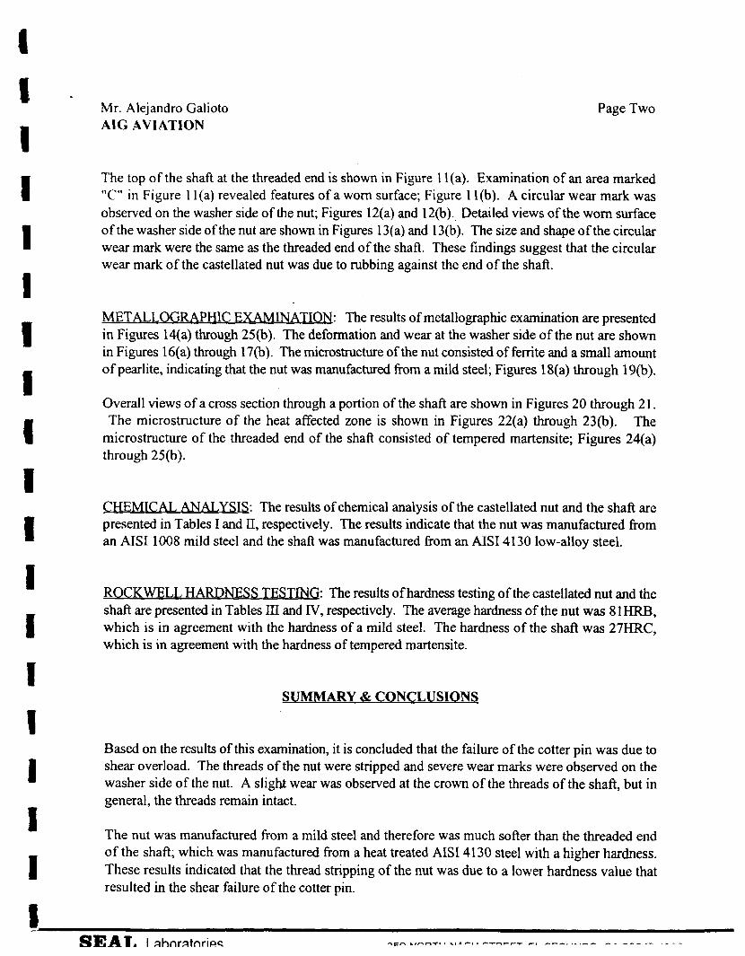
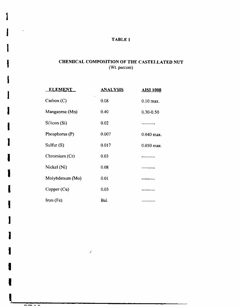
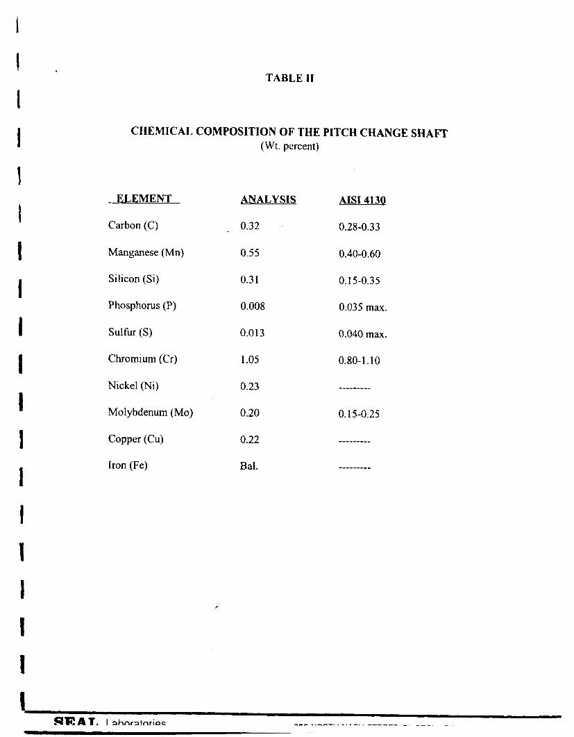
CHEMICAL, ANALYSIS: The results of chemical analysis of the castellated nut and the shaft are presented in Tables I and 11, respectively. The results indicate that the nut was manufactured from an AISI 1008 mild steel and the shaft was manufactured from an AISI 4130 low-alloy steel.
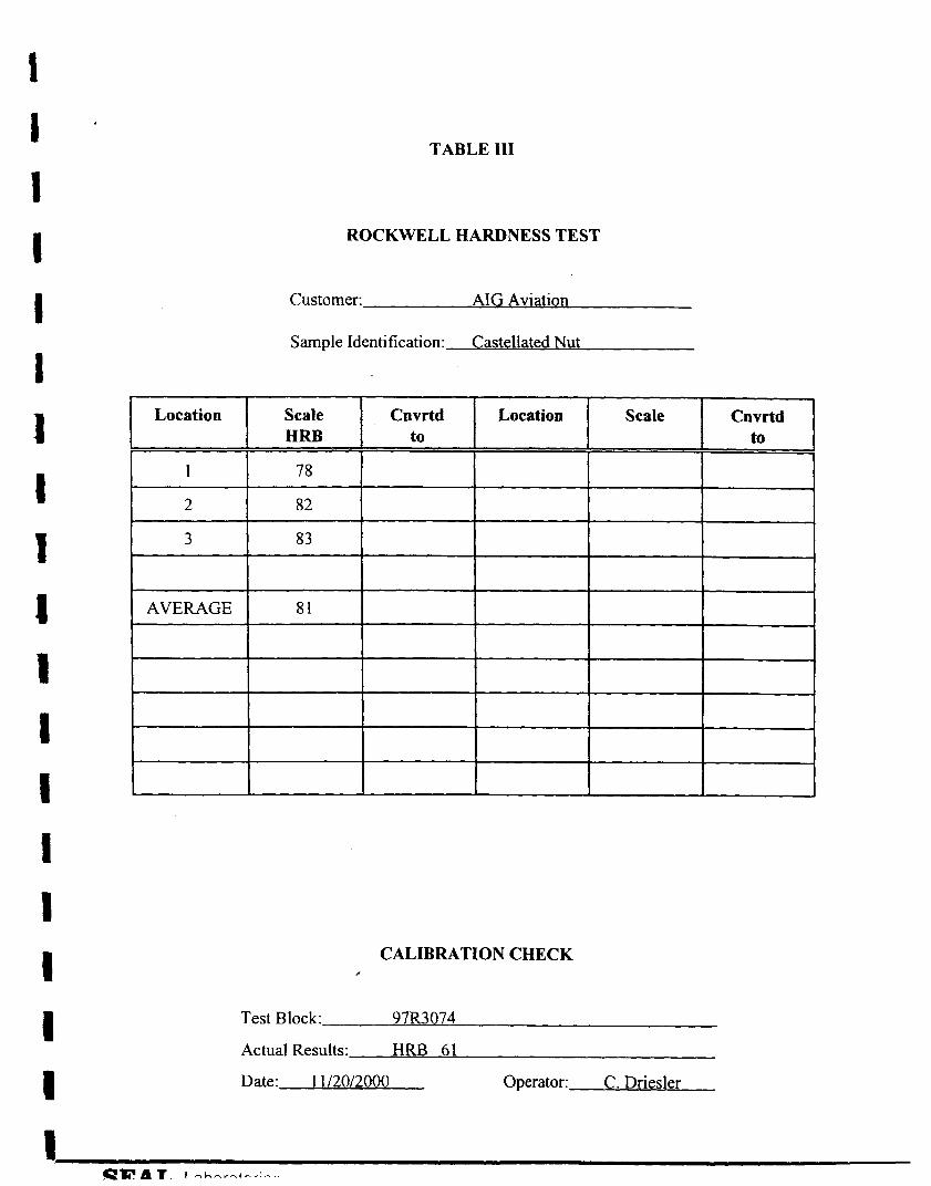
ROCKWELL HARD NESS TESTING: The results of hardness testing of the castellated nut and the shaft are presented in Tables 111 and IV, respectively. The average hardness of the nut was 8 1 HRB, which is in agreement with the hardness of a mild steel. The hardness of the shaft was 27HRC, which is in agreement with the hardness of tempered martensite.
SUMMARY & CONCLUSIONS
Based on the results of this examination, it is concluded that the failure of the cotter pin was due to shear overload. The threads of the nut were stripped and severe wear marks were observed on the washer side of the nut. A slight wear was observed at the crown of the threads of the shaft, but in general, the threads remain intact.
The nut was manufactured from a mild steel and therefore was much softer than the threaded end of the shaft; which was manufactured from a heat treated AISI 4130 steel with a higher hardness. These results indicated that the thread stripping of the nut was due to a lower hardness value that resulted in the shear failure of the cotter pin.
I 1 I 1 I I I I I I 1 I 1 1 1 1 f 1
TABLE I
CHEMICAL COMPOSITION OF THE CASTELLATED NUT (Wt. percent)
ELEMENT ANALYSIS AIS1 1008
Carbon (C)
Manganese (Mn)
Silicon (Si)
Phosphorus (P)
Sulhr (S)
Chromium (Cr)
Nickel (Ni)
Molybdenum (Mo)
Copper (Cu)
Iron (Fe)
0.08
0.40
0.02
0.007
0.017
0.03
0.08
0.0 1
0.03
Bal.
I
1 I I 1 1 I I 1 I I 1 I 1 1 1 1 1
TABLE I1
CHEMICAL COMPOSITION OF THE PITCH CHANGE SHAFT (Wt. percent)
ELEMENT
Carbon (C)
Manganese (Mn)
Silicon (Si)
Phosphorus (P)
Sulfur (S)
Chromium (Cr)
Nickel (Ni)
Molybdenum (Mo)
Copper (Cu)
Iron (Fe)
ANALYSIS
0.32
0.55
0.3 1
0.008
0.013
1.05
0.23
0.20
0.22
Bal.
AlSI 413Q
0.28-0.33
0.40-0.60
0.15-0.35
0.035 max.
0.040 max.
0.80- 1.10
--__-____
0.15-0.25
--------_
---------
I . 1 I I 1 1 I 1 1 1 I 1 1 1 1 1 1
Location
1
2
3
AVERAGE
TABLE 111
Scale Cnvrtd Location Scale Cnvrtd HRB to to
78
82
83
81
ROCKWELL HARDNESS TEST
Customer: AIG Aviation
Sample identification: Castellated Nu t
CALIBRATION CHECK
Test Block: 97R3074
Actual Results: HRF3 61
Date: 1 1/20/2000 Operator: C. Driesler
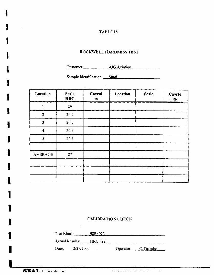
TABLE 1V
Location
1
2
3
4
5
I I 1 I 1 I 1 1 1 1 1 I 1 I 1 1
Scale Cnvrtd Scale Cnvrtd Location HRC to to
29
26.5
26.5
26.5
24.5
ROCKWELL HARDNESS TEST
Customer: AIG Aviation
Sample Identification: Shaft
CALIBRATION CHECK d
Test Block: 98R4923
Actual Results: HRC 28
Date: 12/27/2000 Operator: C . Driesler
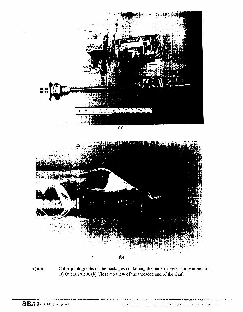
Figure 1 Color photographs of the packages containing the parts received for examination. (a) Overall view. (b) Close-up view of the threaded end of the shaft.

I. ... . , i,._ .. I
- . ..
Figure 2. Color photographs showing close-up views of the threaded end of the shaft. (a) View 1. (b) View 2.
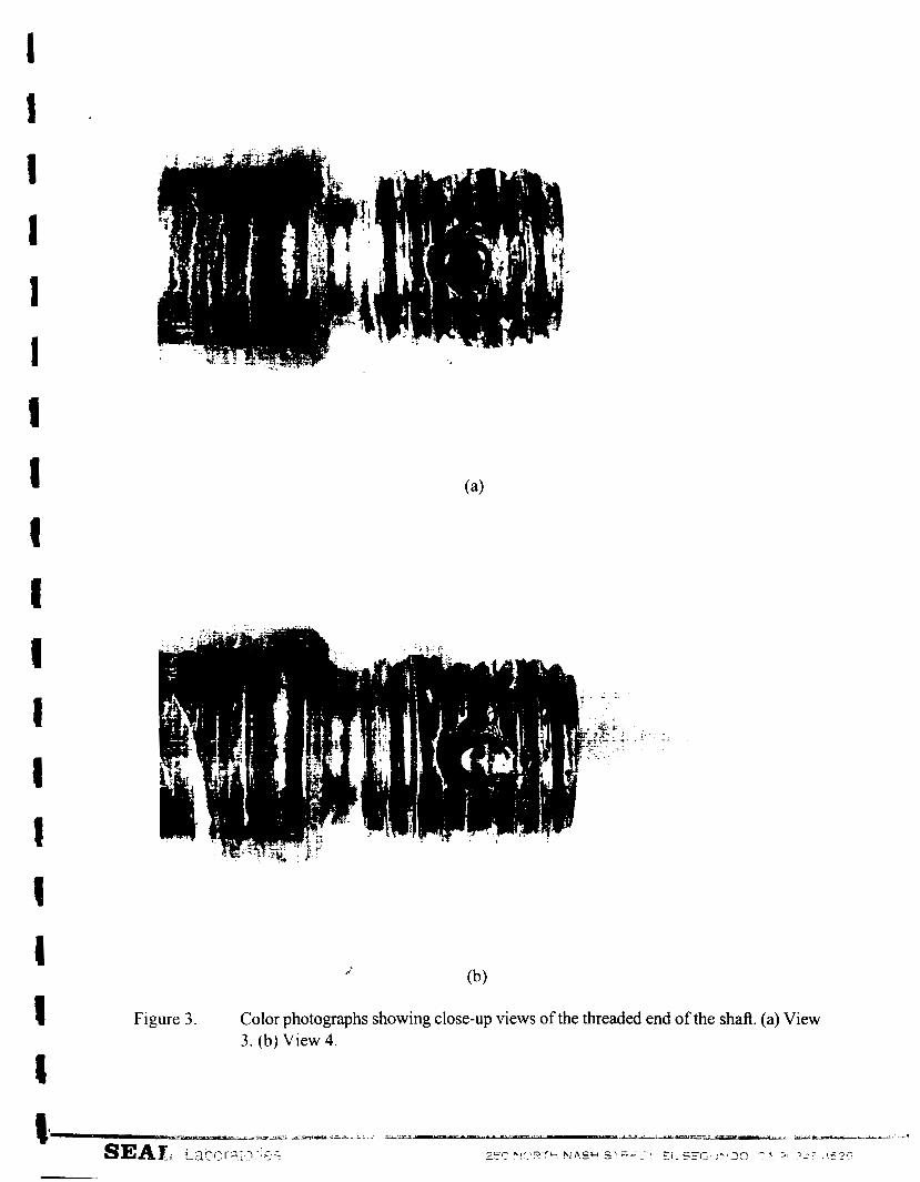
Figure 3 . Color photographs showing close-up views of the threaded end of the shaft. (a) View 3 . (b) View 4.
i
Figure 4. Color photographs of the hardware including the castellated nut received for examination. (a) Overall view. (b) Close-up view of the castellated nut.
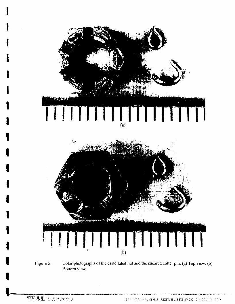
Figure 5 . Color photographs of the castellated nut and the sheared cotter pin. (a) Top view. (b) Bottom view.
I 1
Figure 6 . A color photograph of the castellated nut, showing the locations of various specimens.
i
SEAL Laboratories 250 NORTH NASH STREET. EL SEGUNDO. C A 90245-4529
t -
I
4
t I
Figure 7. SEM photographs of the threaded end of the shaft. (a) Overall view; 1OX. (b) Close- up view of a sheared cotter pin; 50X.
I I 1 1 I i
t
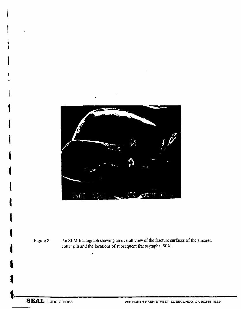
1 Figure 8. An SEM fractograph showing an overall view of the fixture surfaces of the sheared
cotter pin and the locations of subsequent fractographs; SOX. 2
SEAL Laboratories 250 NORTH NASH STREET, EL SEGUNDO. C A 90245.4529
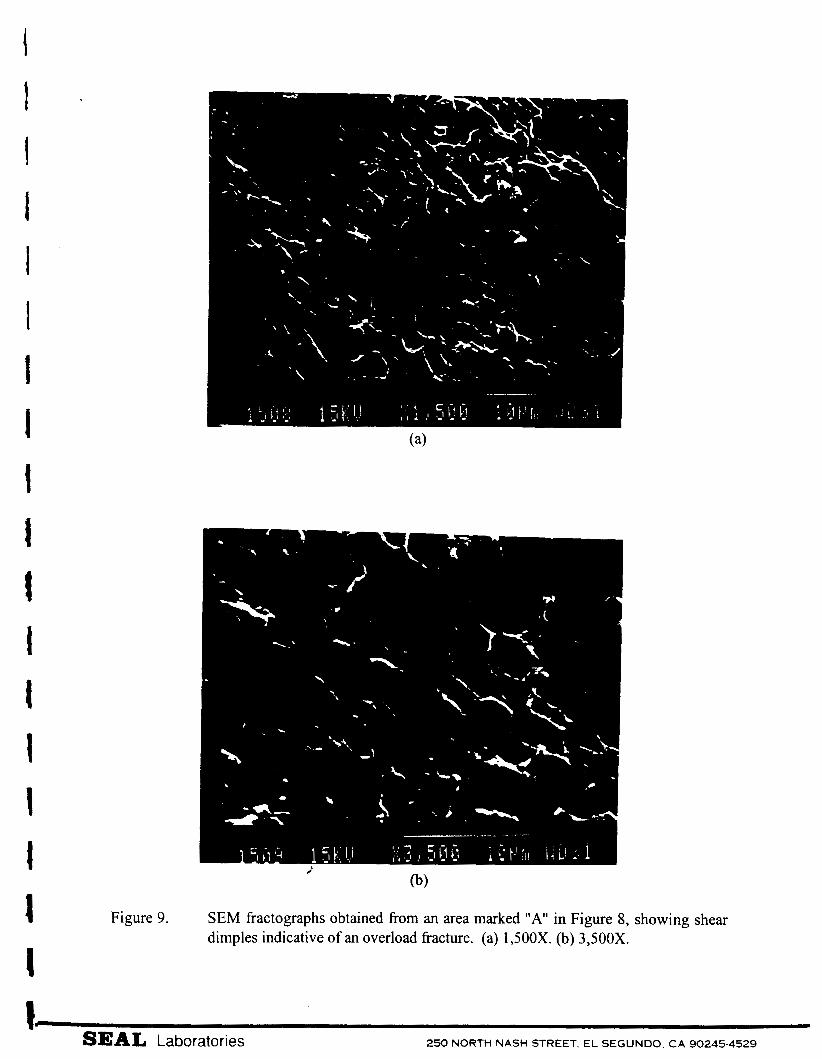
Figure 9. SEM fractographs obtained fiom an area marked "A" in Figure 8, showing shear dimples indicative of an overload fracture. (a) 1,500X. (b) 3,500X.
SEAL Laboratories 250 NORTH NASH STREET, EL SEGUNDO. CA 90245-4529
t
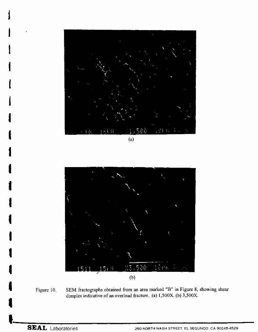
Figure 10. SEM fiactographs obtained from an area marked "B" in Figure 8, showing shear dimples indicative of an overload fracture. (a) 1,500X. (b) 3,500X.
SEAL Laboratories 250 NORTH NASH STREET EL SEGUNDO. C A 90245-4529
?
I
1 I 1
t 1 I
Figure 11, SEM photographs obtained from the end surface of the threaded area of the rod, showing wear. (a) Overall view; 12X. (b) From an area marked "C" in Figure 1 1 (a); 500X.
SEAL, Laboratories 250 NORTH NASH STREET, EL SEGUNDO, C A 90245-4529
ZL
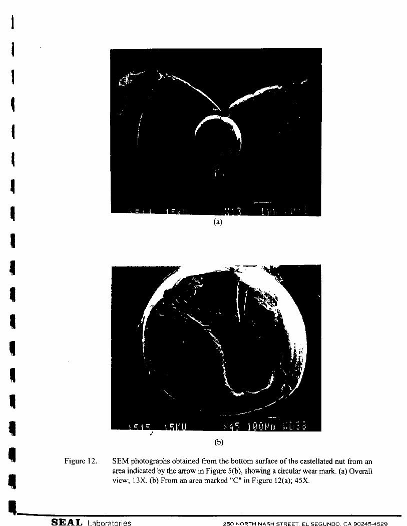
Figure 12. SEM photographs obtained from the bottom surface of the castellated nut from an area indicated by the arrow in Figure 5(b), showing a circular wear mark. (a) Overall view; 13X. (b) From an area marked "C" in Figure 12(a); 45X.
I
Figure 13.
- SEAL
SEM photographs obtained fiom areas indicated in Figure 12(a), showing wear marks on the bottom surface of the castellated nut. (a) From an area marked "D"; 500X. (b) From an area marked "E"; 500X.
Labor ,at o r i es 250 NORTH NASH STREET. EL SEGUNDO. C A 90245. ,4529

![bufora.org.ukbufora.org.uk/documents/BUFORABulletinNo.30Nov1988.pdf · l*",,*,1-@F;1!!{!rl-}i!!..1!!] I",* ** ** , ;;"\:i i ":":, .", I I :i:1;; Lii, ".; I r"r ,ri ;: 6i i; I I I](https://static.fdocuments.in/doc/165x107/5ab0486f7f8b9adb688ebb83/1-f1rl-i1-i-i-i-i-i-i1-lii-i-rr-ri.jpg)