Metallography and Microstructures of Heat-Resistant Alloys · Metallography and Microstructures of...
40
Metallography and Microstructures of Heat-Resistant Alloys George F. Vander Voort and Gabriel M. Lucas, Buehler Ltd. Elena P. Manilova, Polzunov Central Boiler and Turbine Institute,St. Petersburg, Russia HEAT-RESISTANT ALLOYS cover a wide range of chemical compositions, microstructural constituents, and mechanical properties. This ar- ticle summarizes metallographic techniques and microstructural constituents for three types of cast and wrought heat-resistant alloys: iron-base, nickel-base, and cobalt-base. The metallographic methods discussed also are suitable for preparing both cast and wrought heat-resistant alloys; mi- crostructural constituents are quite similar ex- cept for obvious differences in homogeneity and porosity. The procedures used to prepare metallo- graphic specimens of cast or wrought heat-resis- tant grades are quite similar to those for iron- base alloys, especially stainless steels (see the Section “Metallographic Techniques” in this Volume). Aspects particularly significant to the Table 1 Compositions of Fe-Cr-Ni heat-resistant casting alloys Grade Type Composition, % C Mn, max Si, max P, max S, max Cr Ni Mo, max (a) HF 19 chromium, 9 nickel 0.20–0.40 2.00 2.00 0.04 0.04 18.0–23.0 8.0–12.0 0.50 HH 25 chromium, 12 nickel 0.20–0.50 2.00 2.00 0.04 0.04 24.0–28.0 11.0–14.0 0.50 HI 28 chromium, 15 nickel 0.20–0.50 2.00 2.00 0.04 0.04 26.0–30.0 14.0–18.0 0.50 HK 25 chromium, 20 nickel 0.20–0.60 2.00 2.00 0.04 0.04 24.0–28.0 18.0–22.0 0.50 HE 29 chromium, 9 nickel 0.20–0.50 2.00 2.00 0.04 0.04 26.0–30.0 8.0–11.0 0.50 HT 15 chromium, 35 nickel 0.35–0.75 2.00 2.50 0.04 0.04 17.0–21.0 33.0–37.0 0.50 HU 19 chromium, 39 nickel 0.35–0.75 2.00 2.50 0.04 0.04 17.0–21.0 37.0–41.0 0.50 HW 12 chromium, 60 nickel 0.35–0.75 2.00 2.50 0.04 0.04 10.0–14.0 58.0–62.0 0.50 HX 17 chromium, 66 nickel 0.35–0.75 2.00 2.50 0.04 0.04 10.0–14.0 58.0–62.0 0.50 HC 28 chromium 0.50 max 1.00 2.00 0.04 0.04 26.0–30.0 4.0 max 0.50 HD 28 chromium, 5 nickel 0.50 max 1.50 2.00 0.04 0.04 26.0–30.0 4.0–7.0 0.50 HL 29 chromium, 20 nickel 0.20–0.60 2.00 2.00 0.04 0.04 28.0–32.0 18.0–22.0 0.50 HN 20 chromium, 25 nickel 0.20–0.50 2.00 2.00 0.04 0.04 19.0–23.0 23.0–27.0 0.50 HP 26 chromium, 35 nickel 0.35–0.75 2.00 2.50 0.04 0.04 24.0–28.0 33.0–37.0 0.50 (a) Castings having a specified molybdenum range agreed on by the manufacturer and the purchaser may also be furnished under these specifications. Source: ASTM A 297 Table 2 Nominal compositions of nickel- and cobalt-base heat-resistant casting alloys Alloy Composition, % C Cr Mo Nb Ti Al B Zr Fe W V Ta Re Hf Ni Co Nickel-base alloys Alloy 713 C 0.12 12.5 4.2 2 0.80 6.1 0.012 0.10 2.5 ... ... ... ... ... bal ... Alloy 718 0.04 19 3.05 5.13 Ta 0.90 0.50 ... ... 18.5 ... ... ... ... ... bal ... B-1900 0.10 8 6 0.1 max 1 6 0.015 0.08 0.35 0.1 ... 4.3 ... ... bal 10 Hastelloy B 0.10 0.6 28 ... ... ... ... ... 5 ... 0.30 ... ... ... bal 2.5 max Hastelloy C 0.07 16 17 ... ... ... ... ... 5 4 ... ... ... ... bal 2.5 max IN-100 0.15 10 3 ... 4.7 5.5 0.015 0.06 ... ... 1 ... ... ... bal 15 IN-738 0.17 16 1.75 0.9 3.4 3.4 0.01 0.10 0.50 max 2.6 ... 1.75 ... ... bal 8.5 MAR-M 246 0.15 9 2.5 ... 1.5 5.5 0.015 0.05 ... 10 ... 1.5 ... ... bal 10 TRW-NASA VI A 0.13 6.1 2 0.5 1 5.4 0.02 0.13 333 5.5 333 9 0.2 0.43 bal 7.5 U-700 0.15 max 15 5.2 ... 3.5 4.25 0.05 max ... 1 max ... ... ... ... ... bal 18.5 Cobalt-base alloys Haynes 21 0.25 27 5 ... ... ... ... ... 1 ... ... ... ... ... 3 bal Haynes 31 0.50 25.5 ... ... ... ... 0.01 ... 2 7.5 ... ... ... ... 10.5 bal Haynes 151 0.50 20 ... ... ... ... 0.05 ... ... 12.7 ... ... ... ... ... bal MAR-M 302 0.85 21.5 ... ... ... ... 0.005 0.20 ... 10 ... 9 ... ... ... bal MAR-M 509 0.30 24 ... ... 0.20 ... ... 0.50 ... 7 ... 3.5 ... ... 10 bal Wi-52 0.45 21 ... 2 ... ... ... ... 2 11 ... ... ... ... 1.0 max bal ASM Handbook, Volume 9: Metallography and Microstructures G.F. Vander Voort, editor, p820–859 DOI: 10.1361/asmhba0003737 Copyright © 2004 ASM International® All rights reserved. www.asminternational.org
Transcript of Metallography and Microstructures of Heat-Resistant Alloys · Metallography and Microstructures of...

Metallography andMicrostructures of Heat-Resistant AlloysGeorge F. Vander Voort and Gabriel M. Lucas, Buehler Ltd.Elena P. Manilova, Polzunov Central Boiler and Turbine Institute, St. Petersburg, Russia
HEAT-RESISTANT ALLOYS cover a widerange of chemical compositions, microstructuralconstituents, and mechanical properties. This ar-ticle summarizes metallographic techniques andmicrostructural constituents for three types ofcast and wrought heat-resistant alloys: iron-base,
nickel-base, and cobalt-base. The metallographicmethods discussed also are suitable for preparingboth cast and wrought heat-resistant alloys; mi-crostructural constituents are quite similar ex-cept for obvious differences in homogeneity andporosity.
The procedures used to prepare metallo-graphic specimens of cast or wrought heat-resis-tant grades are quite similar to those for iron-base alloys, especially stainless steels (see theSection “Metallographic Techniques” in thisVolume). Aspects particularly significant to the
Table 1 Compositions of Fe-Cr-Ni heat-resistant casting alloys
Grade Type
Composition, %
C Mn, max Si, max P, max S, max Cr Ni Mo, max (a)
HF 19 chromium, 9 nickel 0.20–0.40 2.00 2.00 0.04 0.04 18.0–23.0 8.0–12.0 0.50HH 25 chromium, 12 nickel 0.20–0.50 2.00 2.00 0.04 0.04 24.0–28.0 11.0–14.0 0.50HI 28 chromium, 15 nickel 0.20–0.50 2.00 2.00 0.04 0.04 26.0–30.0 14.0–18.0 0.50HK 25 chromium, 20 nickel 0.20–0.60 2.00 2.00 0.04 0.04 24.0–28.0 18.0–22.0 0.50HE 29 chromium, 9 nickel 0.20–0.50 2.00 2.00 0.04 0.04 26.0–30.0 8.0–11.0 0.50HT 15 chromium, 35 nickel 0.35–0.75 2.00 2.50 0.04 0.04 17.0–21.0 33.0–37.0 0.50HU 19 chromium, 39 nickel 0.35–0.75 2.00 2.50 0.04 0.04 17.0–21.0 37.0–41.0 0.50HW 12 chromium, 60 nickel 0.35–0.75 2.00 2.50 0.04 0.04 10.0–14.0 58.0–62.0 0.50HX 17 chromium, 66 nickel 0.35–0.75 2.00 2.50 0.04 0.04 10.0–14.0 58.0–62.0 0.50HC 28 chromium 0.50 max 1.00 2.00 0.04 0.04 26.0–30.0 4.0 max 0.50HD 28 chromium, 5 nickel 0.50 max 1.50 2.00 0.04 0.04 26.0–30.0 4.0–7.0 0.50HL 29 chromium, 20 nickel 0.20–0.60 2.00 2.00 0.04 0.04 28.0–32.0 18.0–22.0 0.50HN 20 chromium, 25 nickel 0.20–0.50 2.00 2.00 0.04 0.04 19.0–23.0 23.0–27.0 0.50HP 26 chromium, 35 nickel 0.35–0.75 2.00 2.50 0.04 0.04 24.0–28.0 33.0–37.0 0.50
(a) Castings having a specified molybdenum range agreed on by the manufacturer and the purchaser may also be furnished under these specifications. Source: ASTM A 297
Table 2 Nominal compositions of nickel- and cobalt-base heat-resistant casting alloys
Alloy
Composition, %
C Cr Mo Nb Ti Al B Zr Fe W V Ta Re Hf Ni Co
Nickel-base alloys
Alloy 713 C 0.12 12.5 4.2 2 0.80 6.1 0.012 0.10 2.5 . . . . . . . . . . . . . . . bal . . .Alloy 718 0.04 19 3.05 5.13 � Ta 0.90 0.50 . . . . . . 18.5 . . . . . . . . . . . . . . . bal . . .B-1900 0.10 8 6 0.1 max 1 6 0.015 0.08 0.35 0.1 . . . 4.3 . . . . . . bal 10Hastelloy B 0.10 0.6 28 . . . . . . . . . . . . . . . 5 . . . 0.30 . . . . . . . . . bal 2.5 maxHastelloy C 0.07 16 17 . . . . . . . . . . . . . . . 5 4 . . . . . . . . . . . . bal 2.5 maxIN-100 0.15 10 3 . . . 4.7 5.5 0.015 0.06 . . . . . . 1 . . . . . . . . . bal 15IN-738 0.17 16 1.75 0.9 3.4 3.4 0.01 0.10 0.50 max 2.6 . . . 1.75 . . . . . . bal 8.5MAR-M 246 0.15 9 2.5 . . . 1.5 5.5 0.015 0.05 . . . 10 . . . 1.5 . . . . . . bal 10TRW-NASA VI A 0.13 6.1 2 0.5 1 5.4 0.02 0.13 333 5.5 333 9 0.2 0.43 bal 7.5U-700 0.15 max 15 5.2 . . . 3.5 4.25 0.05 max . . . 1 max . . . . . . . . . . . . . . . bal 18.5
Cobalt-base alloys
Haynes 21 0.25 27 5 . . . . . . . . . . . . . . . 1 . . . . . . . . . . . . . . . 3 balHaynes 31 0.50 25.5 . . . . . . . . . . . . 0.01 . . . 2 7.5 . . . . . . . . . . . . 10.5 balHaynes 151 0.50 20 . . . . . . . . . . . . 0.05 . . . . . . 12.7 . . . . . . . . . . . . . . . balMAR-M 302 0.85 21.5 . . . . . . . . . . . . 0.005 0.20 . . . 10 . . . 9 . . . . . . . . . balMAR-M 509 0.30 24 . . . . . . 0.20 . . . . . . 0.50 . . . 7 . . . 3.5 . . . . . . 10 balWi-52 0.45 21 . . . 2 . . . . . . . . . . . . 2 11 . . . . . . . . . . . . 1.0 max bal
ASM Handbook, Volume 9: Metallography and Microstructures G.F. Vander Voort, editor, p820–859 DOI: 10.1361/asmhba0003737
Copyright © 2004 ASM International® All rights reserved. www.asminternational.org

preparation of cast or wrought heat-resistant al-loys are emphasized. Tables 1 to 3 list the nom-inal compositions of Fe-Ni-Cr Alloy Casting In-stitute H-series alloys and other iron-nickel,nickel-, and cobalt-base cast and wrought heat-resistant alloys, respectively.
Macroetching
Cast and wrought heat-resistant alloys are ex-amined for macrostructure in the same manneras tool steels and stainless steels. Macroetchingof cast specimens is generally performed as aresearch tool to study the solidification charac-teristics; macroetching of wrought specimenscan be performed as part of a research study butis more commonly performed as a required testby product specifications and is, therefore, a rou-tine production test. To evaluate castings, thedisk is generally removed so that the etched sur-face (ground smooth before etching for best re-sults) is parallel to the solidification direction.For wrought alloys, disks are cut (usually fromwrought billet samples) at representative loca-tions, such as the top and bottom of ingots orremelted (electroslag remelted or vacuum arc re-melted) stock, and are ground before macroetch-ing. Macroetchants for the cast or wrought aus-
tenitic Fe-Ni-Cr heat-resistant alloys are thesame as those recommended for cast andwrought austenitic stainless steels (see the article“Metallography and Microstructures of StainlessSteels” in this Volume). Macroetchants for castand wrought iron-nickel-, nickel-, and cobalt-base heat-resistant alloys are given in Table 4.
Features observed on the macroetched castdisks depict the results of solidification. Near thesurface, the grain structure will be finer thanelsewhere. Dendrites will be visible, with the pri-mary axis in the solidification direction. Segre-gation and shrinkage cavities may also be ob-served. Porosity due to gas evolution is unlikelyto be seen. Macroetch features on disks fromconsumable-electrode remelted superalloys aredifferent from those observed in ingot cast steels.Unique macroetch features observed in these re-melted alloys include freckles, radial segrega-tion, and ring patterns (Ref. 1–7). Freckles aredark-etching spots due to localized segregationor to enrichment in carbides or Laves phase.They are detrimental to material quality. The mi-crostructure of a freckle in Rene 41 is shown inFig. 1. Radial segregation appears as dark-etch-ing elongated spots in a radial or spiral pattern.Ring patterns are concentric rings that etchlighter (usually) or darker than the matrix. Theyare revealed only by macroetching. The nature
of ring patterns remains obscure. Examinationhas revealed little difference between ring andmatrix areas and no measurable influence on me-chanical properties.
Specimen Preparation
Sectioning. Various sectioning devices havebeen used with heat-resistant alloys. The usualprecautions regarding excessive heating shouldbe followed. For austenitic grades, which aresensitive to deformation, the more vigorous sec-tioning techniques, such as band sawing orpower hacksawing, will introduce excessive dis-tortion or work hardening, depending on the al-loy and heat treatment condition. Such methodsare suitable for initial sectioning of large pieces,but final cutting of specimens should be per-formed using abrasive cutoff machines withabrasive blades designed for metallographicwork (blades designed for production cutting in-troduce too much damage and should not be usedfor metallography). Heavy deformation intro-duced by sawing may be difficult, if not impos-sible, to remove by subsequent grinding and pol-ishing steps. Abrasive cutoff wheels used areusually the consumable type. Coolant flow mustbe adequate and uniformly distributed to mini-
Table 3 Nominal compositions of wrought heat-resistant alloys
Alloy
Composition, %
C Fe Ni Co Cr Ti Mo Others
Iron-nickel-base alloys
A-286 (AISI 660) 0.05 bal 26.0 . . . 15.0 2.15 1.25 0.3 V, 0.2 Al, 0.003 BGreek Ascoloy 0.18 bal 2.0 . . . 13.0 . . . 0.50 max 3.0 WMoly Ascoloy 0.12 bal 2.5 . . . 12.0 . . . 1.75 0.70 Mn, 0.32 V, 0.025 NIncoloy 800 0.05 bal 32.5 . . . 21.0 0.38 . . . 0.38 AlIncoloy 901 0.05 bal 42.7 . . . 13.5 2.5 6.2 0.25 AlAISI 330 0.05 bal 36.0 . . . 19.0 . . . . . . . . .Hastelloy X (AISI 680) 0.10 max 18.5 bal 1.5 22.0 . . . 9.0 0.6 WPyromet 31 0.04 bal 55.5 . . . 22.7 2.5 2.0 1.5 Al, 1.1 Nb, 0.005 BAlloy 718 0.04 18.5 bal . . . 19.0 0.9 3.05 5.13 Nb � Ta, 0.5 Al
Nickel-base alloys
Astroloy 0.06 . . . bal 17.0 15.0 3.5 5.25 4.0 Al, 0.03 BHastelloy B . . . 5.0 bal 2.5 max 1.0 max . . . 28.0 . . .Hastelloy C 0.07 5.0 bal 2.5 max 16.0 . . . . . . 4.0 WHastelloy C-276 0.02 5.5 bal 2.5 max 15.5 . . . 16.0 3.75 W, 0.35 VHastelloy G30 0.03 max 15 bal 5.0 max 30 . . . 5.0 1.0 Nb � TaHastelloy W 0.12 max 5.5 bal 2.5 5.0 . . . 24.5 0.6 VAlloy 600 0.1 max 8.0 bal . . . 15.5 . . . . . . . . .Alloy 617 0.07 . . . bal 12.5 22 . . . 9.0 1.0 AlAlloy 625 0.1 max 5.0 max bal 1.0 max 21.5 0.4 max 9.0 3.65 Nb � Ta, 0.4 Al maxAlloy X-750 0.04 7.0 bal . . . 15.5 2.5 . . . 0.95 Nb � Ta, 0.7 AlZMI-3U 0.08 . . . bal 5.5 13 5.0 1.2 5.0 W, 3.0 Al, 0.015 BCNK7 0.08 . . . bal 9.0 14.8 4.2 0.4 7.0 W, 0.01 B, 0.02 CeRene 41 0.09 . . . bal 11.0 19.0 3.1 10.0 1.5 Al, 0.010 B maxRene 95 0.15 . . . bal 8.0 14.0 2.5 3.5 3.5 Al, 3.5 W, 3.5 NbU-520 0.05 . . . bal 12.0 19.0 3.0 6.0 1.0 W, 2.0 Al, 0.005 BU-700 0.15 max 1.0 max bal 18.5 15.0 3.5 5.2 4.25 Al, 0.05 BU-710 0.07 . . . bal 15.0 18.0 5.0 3.0 2.5 Al, 1.5 W, 0.02 BU-720 0.035 . . . bal 14.7 18.0 5.0 3.0 1.25 W, 2.5 Al, 0.035 BWaspaloy 0.07 . . . bal 13.5 19.5 3.0 4.3 1.4 Al, 0.07 Zr, 0.006 BHaynes HR-160 0.05 2.0 37.0 29.0 28.0 . . . . . . 0.5 Mn
Cobalt-base alloys
Haynes 25 (L-605) 0.10 . . . 10.0 bal 20.0 . . . . . . 15.0 W, 1.5 Mn, 0.55 SiHaynes 188 0.10 1.5 22.0 bal 22.0 . . . . . . 14.0 W, 0.08 LaStellite 6B 1.1 3.0 max 3.0 max bal 30.0 . . . . . . 4.5 WS-816 0.38 4.0 20.0 bal 20.0 . . . 4.0 4.0 W, 4.0 NbMP35N 0.025 max 1.0 max 35.0 bal 20.0 1.0 max 10.0 0.010 B max
Metallography and Microstructures of Heat-Resistant Alloys / 821
mize heat-induced damage. Sectioning of castnickel alloys and all cobalt-base alloys requiresuse of an abrasive blade that breaks down at ahigh rate, exposing fresh, sharp particles in thecutting zone. These are the most difficult gradesto section of the heat-resistant alloys.
Mounting. Many bulk specimens can beground and polished without mounting, althoughspecimen identification is generally limited tostamp marks, such as a job number and a spec-imen number. Some automatic grinding and pol-ishing devices require a mounted specimen, usu-ally 25, 32, or 38 mm (1, 11⁄4, or 11⁄2 in.) indiameter; others do not. Mounting facilitates pol-ishing of small or irregularly shaped specimens.
When it is necessary to view the microstruc-ture at the extreme edge of a specimen, it mustbe mounted. Edge retention of nonmountedspecimens is inferior, and examination above100� magnification may be impossible. Opti-mal results are obtained when the edge of inter-est is plated with electroless or electrolytic nickelbefore mounting (see the article “Mounting ofSpecimens” in this Volume). However, excellentresults can be obtained without plating if the
specimen is mounted using a compression-molded thermosetting epoxy resin containing afiller material, such as Epomet (Buchler Ltd.)resin. This resin provides near-freedom fromshrinkage gaps between specimen and mountthat lead to edge rounding and bleed-out prob-lems. Edge retention is much better when auto-mated grinding-polishing devices are used.Rigid grinding disks provide superb edge flat-ness, and napless, woven cloths or pressed pads
preserve that flatness through to the final step. Amedium-nap cloth can be used for the final pol-ishing step without problems, unless shrinkagegaps are present between specimen and mount-ing material. When shrinkage gaps are present,use a polyurethane pad for the final step.
When edge retention is not a primary require-ment, specimens can be mounted using any ofthe popular compression-mounting materials orcastable resins. Most produce acceptable results;
Table 4 Macroetchants for wrought heat-resistant alloys
Composition(a) Comments
1. 1 part 30% H2O2, 2 parts HCl, 2 or 3 parts H2O Recommended for nickel-chromium alloys; use fresh solution;reveals grain structure; if the surface is stained, removewith 50% aqueous HNO3; etch approximately 2 min
2. (a) 15 g (NH4)2S2O8 (ammonium persulfate) and 75mL H2O
(b) 250 g FeCl3 and 100 mL HCl(c) 30 mL HNO3
Lepito’s macroetch for general macrostructure and weldments;mix a and b, add c; immerse 30–120 s at room temperature
3. 200 g FeCl3, 200 mL HCl, H2O to 1000 mL For nickel-base superalloys; etch to 90 min at 100 �C (212 �F)4. HCl saturated with FeCl3 For cobalt-base superalloys; add 5% HNO3 before use at
room temperature; clean surface by dipping in 50%aqueous HCl
5. (a) 21 mL H2SO4, 15 mL HCl, 21 mL HNO3, 21 mLHF, 22 mL H2O
(b) 40 mL 20% aqueous CuCl2 (copper chloride), 40mL HCl, 20 mL HF
For cobalt-base superalloys; etch 5 min in a, then 5 min in b
6. 50 mL saturated aqueous CuSO4 (copper sulfate) and50 mL HCl
For iron-nickel- and nickel-base alloys; swab or immerse,room temperature
(a) Whenever water is specified, use distilled water.
Table 5 Preparation method for Fe-Ni-Cr- and nickel-base heat-resisting alloys
Surface Abrasive/size
Load/specimen
Base speed, rpm/direction Time, minN lbf
Waterproof paper (water cooled) 220–240-grit (P240–P280) SiC 27 6 240–300Complementary or contra
Until plane
Silk cloth (PSA backing) 9 lm diamond with lubricant 27 6 120–150Complementary or contra
5
Polyester cloth 3 lm diamond with lubricant 27 6 120–150Complementary or contra
4
Polyester cloth 1 lm diamond with lubricant 27 6 120–150Complementary or contra
3
Synthetic rayon medium-nap cloth 0.05 lm alumina suspension 27 6 100–150Complementary or contra
3
Note: PSA, pressure-sensitive adhesive. Other surfaces can be substituted in step 1, as long as the abrasive size is similar (for example, a diamondgrinding disc or a rigid grinding disc could be used). In step 1, remove the damage from sectioning and get all of the specimens in the holder to acommon plane. In steps 2 to 4, charge the cloth first with diamond in paste form. With a clean fingertip, press the paste into the cloth. Apply lubricant.During the cycle, periodically add diamond of the same size as a suspension to keep the cutting rate high. Step 4 is optional. Use it for the mostdifficult specimens. Use contra rotation if the specimen holder motor rotates at �100 rpm. At higher speeds, the suspensions, particularly the alumina,will be splattered all over the walls. Contra rotation is slightly more aggressive and gives better flatness. If the head rotates �100 rpm, the suspensionwill stay on the cloth better (in complementary rotation, the centrifugal forces shoot the suspensions off the platen and down the drain).
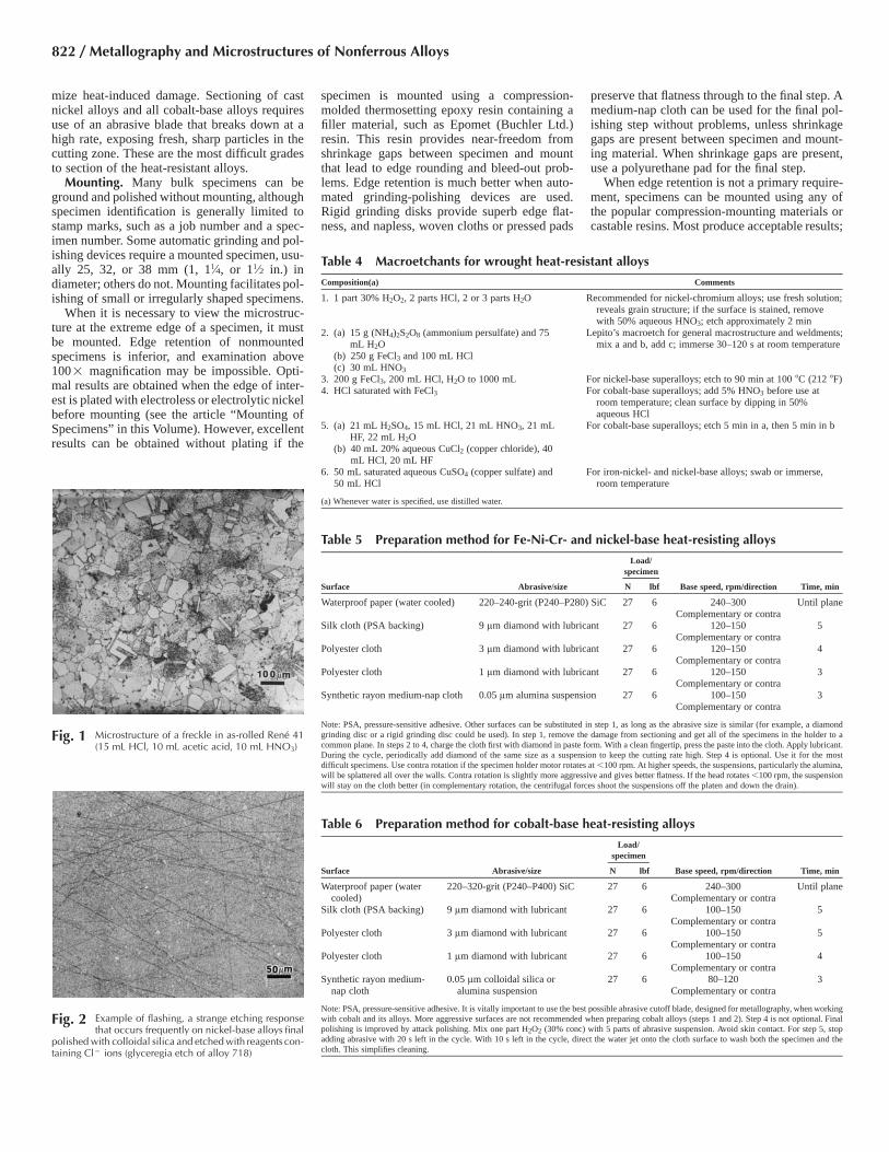
Fig. 2 Example of flashing, a strange etching responsethat occurs frequently on nickel-base alloys final
polished with colloidal silica and etched with reagents con-taining Cl� ions (glyceregia etch of alloy 718)
Fig. 1 Microstructure of a freckle in as-rolled Rene 41(15 mL HCl, 10 mL acetic acid, 10 mL HNO3)
Table 6 Preparation method for cobalt-base heat-resisting alloys
Surface Abrasive/size
Load/specimen
Base speed, rpm/direction Time, minN lbf
Waterproof paper (watercooled)
220–320-grit (P240–P400) SiC 27 6 240–300Complementary or contra
Until plane
Silk cloth (PSA backing) 9 lm diamond with lubricant 27 6 100–150Complementary or contra
5
Polyester cloth 3 lm diamond with lubricant 27 6 100–150Complementary or contra
5
Polyester cloth 1 lm diamond with lubricant 27 6 100–150Complementary or contra
4
Synthetic rayon medium-nap cloth
0.05 lm colloidal silica oralumina suspension
27 6 80–120Complementary or contra
3
Note: PSA, pressure-sensitive adhesive. It is vitally important to use the best possible abrasive cutoff blade, designed for metallography, when workingwith cobalt and its alloys. More aggressive surfaces are not recommended when preparing cobalt alloys (steps 1 and 2). Step 4 is not optional. Finalpolishing is improved by attack polishing. Mix one part H2O2 (30% conc) with 5 parts of abrasive suspension. Avoid skin contact. For step 5, stopadding abrasive with 20 s left in the cycle. With 10 s left in the cycle, direct the water jet onto the cloth surface to wash both the specimen and thecloth. This simplifies cleaning.
822 / Metallography and Microstructures of Nonferrous Alloys
each resin has advantages and disadvantages.The selection of a particular resin is often basedon familiarity or cost.
Grinding of specimens takes place by handor by use of automatic devices. Hand grindingshould be avoided, if at all possible, because thespecimens cannot be kept perfectly flat duringgrinding. Grinding is most commonly performedusing water-cooled silicon carbide (SiC) paper at240 to 300 rpm. Today, a variety of other grind-ing formats are available, although SiC remainsvery popular. Historically, the usual grit-size se-quence was 120, 240, 320, 400, and 600 grit(P120, P280, P400, P600, and P1200 in the Fed-eration of European Producers of Abrasives, orFEPA, scale); finer grits were occasionally used.Today, preparation procedures employ only onegrinding step before switching to diamond abra-sives on a napless woven cloth or a pressed pad.When proper metallographic abrasive bladeshave been used to section the specimens, so thatcutting damage is minimal and the surface finishis optimal, grinding should commence with thefinest possible abrasive, such as 180-, 240-, or320-grit SiC (P180, P280 or P400 in the FEPAscale). The coarser the abrasive, the greater thedamage introduced by grinding. Thus, when cut-ting damage is minimal, a finer-size abrasive canbe used for the grinding step. This removes thedamage from cutting while imparting less dam-age than a coarser grit size grinding abrasive.
Moderately heavy pressure is used for handgrinding. The specimen must be held flat againstthe paper. After each grinding, the specimen isrinsed, wiped clean, and rotated 45 to 90� beforegrinding with the next paper. Grinding shouldproceed for approximately twice as long asneeded to remove all the scratches from the pre-vious step; 1 to 2 min per step is usually ade-quate. Automated grinding devices produceomni-directional scratch patterns. Heat-resistantalloys are not susceptible to embedding of sili-con carbide from the grinding paper, but if thespecimen contains cracks or pores, it may be ad-visable to clean ultrasonically after each step.For most specimens, a simple wash under run-ning water will remove any loose abrasive orgrinding debris. Specimens should be rinsed inalcohol (preferably ethanol) and dried with hotair.
Rough polishing, historically, often beganwith 6 or 3 lm diamond abrasive, generally as apaste, although aerosols or slurries were alsoused. Diamond abrasives have largely replaceduse of 5 lm alumina (Al2O3) for rough polishing,except where economic considerations do notpermit use of diamond abrasives. In modern pro-cedures, the grinding step is usually followed by9 or 6 lm diamond on a napless, woven cloth orpressed pad. This step is followed by one or twomore diamond abrasive steps, depending on thedifficulty in preparing the alloy, or on the degreeof perfection desired by the metallographer. Peo-ple in production laboratories often believe thatthey save time and money by preparing speci-mens “just good enough” for their work. How-ever, one does not know that “just good enough”
is really good enough until the specimen hasbeen properly prepared. If the metallographer issimply asked to rate the grain size of a specimenaccording to a chart method, then some degreeof imperfection can be tolerated. However, infailure analysis, research and many quality stud-ies, important information will be missed if thespecimen is not prepared properly so that the truestructure can be seen.
Although a wide range of cloths is available,low-nap or napless cloths are preferred for roughpolishing, although canvas, which was quitepopular, provides economical durability. Today,woven, napless cloths, such as natural silk orsynthetic nylon or polyester, are recommended,because they provide good cutting rates, excel-lent surface flatness, and good surface finishesfor each abrasive size used. Synthetic, naplesschemo-textile pads are also used. Billiard clothand red felt have been used, but they can causeexcessive relief, poor edge retention, pull-outs,and other artifact problems, especially if the lu-brication level is not correct. A lubricant/ex-tender fluid, compatible with the diamond abra-sive, should always be added to reduce frictionand drag and to promote more efficient cutting.Wheel speeds for polishing are 100 to 150 rpm,in most work. Moderate pressure is applied.
During hand polishing, the specimen shouldbe rotated counter to wheel rotation while it ismoved slowly from center to edge. Again, thespecimen must be held firmly against the wheelto avoid rocking. Polishing should continue untilgrinding scratches are removed; 1 to 2 min isusually adequate. With an automated machine,the specimen rotates in either the same directionor the opposite direction to the platen (comple-mentary or contra rotation, respectively). Contrarotation is slightly more aggressive. It is bestused when the specimen holder rotates at �90
rpm. If the head operates at a higher speed, theabrasive may be thrown off the platen surfaceonto the operator and the walls. When the headrotates at �90 rpm, it stays on the platen surfacenicely during the cycle. When the head rotatesin the same direction as the platen (complemen-tary), the abrasive is thrown off the platen, intothe surrounding bowl, and down the drain dueto centrifugal force, regardless of the head speed.Of course, the faster the platen and head speed,the greater the centrifugal force, and the fasterthe abrasive goes down the drain.
A second diamond-polishing step, generallyusing 3 or 1 lm diamond, is usually performedin modern methods but was optional in the for-mer “traditional” methods. A synthetic suedemedium-nap cloth was commonly used, butother cloths may also yield good results. Thisstep is carried out in the same manner as theinitial diamond polishing. After each diamondpolishing step, the specimen should be carefullycleaned to remove abrasive, extender oil, andpolishing debris. Ultrasonic cleaning producesexcellent results but is not always required, es-pecially with wrought specimens. With a castspecimen that contains voids, it may be best toultrasonically clean after each preparation step.Today, medium-nap cloths are no longer rec-ommended for use with diamond abrasives inmost polishing routines. Instead, woven, naplesscloths or pressed chemo-textile pads are pro-moted, because flatness and edge retention arebetter.
Final polishing, historically, involved one ormore steps, depending on the need to remove allscratches. For routine examination, polishing toa 1 lm diamond finish may be adequate. Whenphotomicroscopy is anticipated, additional stepsare usually required. A wide range of final pol-ishing abrasives may be used. Alumina slurries
Table 7 Electropolishing techniques for wrought heat-resistant alloys
Electrolyte composition Comments
1. 37 mL H3PO4, 56 mL glycerol, 7 mL H2O For Inconel 625, use 1.2–1.6 A/cm2 (8–10 A/in.2); for Incoloy800, use 3.1 A/cm2 (20 A/in.2); platinum cathode
2. 25 mL H3PO4, 25 mL HNO3, 50 mL H2O For Inconel 600 and X-750, use 17.8 A/cm2 (115 A/in.2), 5–10 s; platinum cathode
3. 144 mL ethanol, 10 g AlCl3 (anhydrous aluminumchloride), 45 g ZnCl2 (anhydrous zinc chloride), 16 mLN-butyl alcohol, 32 mL H2O
For cobalt-base superalloys, use 23–25 V dc at roomtemperature with successive 1 min periods
4. 40 mL HClO4 (perchloric acid), 450 mL acetic acid, 15mL H2O
For Nimonic alloys, use 15 V dc, 0.1 A/cm2 (0.65 A/in.2),below 25 �C (77 �F)
5. 10 mL HClO4 and 90 mL acetic acid For nickel-base alloys, use at 0.5–0.9 A/cm2 (3–6 A/in.2), 30s for aged specimens, longer for solution-annealed ones;keep cool (10-15 �C, or 50-60�F); best results by polishingin 5 s intervals
6. 70 mL methanol and 10 mL H2SO4 For nickel-base superalloys, use at 20–25 V dc, 0.3–0.8 A/cm2 (2–5 A/in.2), room temperature; 10–15 s after a 600-grit finish or 5 s after a 0.3 lm Al2O3 finish; c� slightlyetched, carbides in relief
7. 60 mL methanol, 10 mL H2SO4, 5 mL HCl Use same as No. 6; produces more etching of c� phase; ifHNO3 is substituted for HCl, the surface will be smoothwithout relief or attack.
8. 7 mL ethanol, 20 mL HClO4, 10 mL glycerol Use same as No. 6; mix carefully, keep cool; producessmooth surfaces
9. 15 mL HCl and 85 mL methanol For nickel-base superalloys, use at 30–40 V dc, 0.3–1.2 A/cm2 (2–8 A/in.2), at room temperature for 5–10 s after a600-grit silicon carbide finish or 2–5 s after a 0.3 lm Al2O3
finish; produces strong carbide relief, etches c�; very goodfor SEM examination
Metallography and Microstructures of Heat-Resistant Alloys / 823

are quite common, using 0.3 and/or 0.05 lmAl2O3. Nearly all alumina abrasives are pro-duced by the calcination process, and agglom-erates are always present, even in the deagglom-erated abrasives. However, alumina is nowavailable in the 0.05 lm size, made by the sol-gel process where the particles are grown froma solution. This abrasive, called MasterPrep(Buehler Ltd.) alumina, produces superior re-sults compared to ordinary aluminas and is freeof the problems associated with the use of col-loidal silica.
Colloidal silica (Ref 1) produces excellent re-sults with these alloys but is more difficult to use.The amorphous silica particles will crystallize ifthe solution evaporates. This ruins the cloth.Specimens must be carefully cleaned, because awhitish film may be present that will alter etchresponse. To clean the surface, stop adding abra-sive with approximately 20 s left in the cycle(using an automated polisher). With approxi-mately 10 s left in the cycle, direct the water jetonto the cloth surface. The specimen and thecloth will be cleaned simultaneously. When themachine stops, rinse the sample holder underrunning water, scrub the surfaces with ethanol,and blow dry. However, even with this precau-tion, strange etch results can occur. For example,when swab etching with reagents such as gly-ceregia, it usually takes approximately 60 to 120s to bring up etch detail and make the surfaceappear to be etched to the proper level by eye.However, after using colloidal silica, sometimeswhen etching with reagents that contain Cl�
ions, the surface immediately turns dull gray assoon as the etchant touches the specimen (called“flashing”). This produces a heavy craze-crackappearance when viewed microscopically (Fig.2). This false structure cannot be removed bysimply repeating the last preparation step. In-stead, one must go back to approximately a 240-grit (P280) SiC abrasive to remove the affectedlayer. Interestingly, electrolytic etchants neverproduce this problem. To avoid this problem,start the final step with colloidal silica, flush itoff with water, and complete the cycle using thesol-gel alumina slurry. One can split the totaltime equally between the two abrasives or useany desired percentage of time with each, as longas approximately 10 s are dedicated at the endof the cycle to the sol-gel alumina abrasive.Again, use the previously mentioned cleaningprocedure to clean both the cloth and specimenbefore the cycle ends, or use only the sol-gelalumina suspension.
Cleaning between steps is important, becausecontamination can occur. In many cases, theholder can be simply rinsed under running waterto remove the debris. However, it is often nec-essary to scrub the surfaces with ethanol to re-move adherent debris. If this falls down onto thecloth in the next step, the cloth will be contam-inated, and the results will be poor. The opera-tor’s hands must also be cleaned after each step,because contamination can result if this is notdone. Cleanliness is important in metallography,and this extends to the entire laboratory.
Final polishing is generally performed using asynthetic suede medium-nap cloth or a polyure-thane pad at 100 to 150 rpm. During hand polish-ing, the specimen should be rotated counter to thewheel rotation direction while it is moved fromcenter to edge. The slurry is added periodically to
the cloth during polishing. Moderate pressure isused, and care must be taken to avoid rocking thespecimen. A polishing time of 1 to 2 min is usu-ally adequate. After polishing, the specimenshould be carefully cleaned and dried to avoidstaining, and the operator’s hands must be
Table 8 Microetchants for wrought heat-resistant alloys
Composition Comments
1. 2 parts glycerol, 3 parts HCl, 1 part HNO3 Glyceregia; mix fresh, do not store; discard when solution is orange;use by immersion or swabbing 5–60 s; very popular general etch forstructure of iron- and nickel-base superalloys; c� in relief
2. 5 mL HF, 10 mL glycerol, 85 mL ethanol Electrolytic etch at 0.04–0.15 A/cm2 (0.25–1.0 A/in.2), 6–12 V dc; fornickel-base alloys, c� in relief; stop etch when edges are brownish;excellent etch for transmission electron microscopy (TEM) replicawork
3. 12 mL H3PO4, 47 mL H2SO4, 41 mL HNO3 Electrolytic etch at 6 V dc, 0.12–0.15 A/cm2 (0.75–1.0 A/in.2), a fewseconds; add to 100 mL H2O to slow etch; for nickel-base alloys;use under hood; mix H3PO4 and HNO3, then add H2SO4; stainsmatrix when c� is present; good for revealing segregation and forexamining c� with TEM replicas; attacks Bakelite (Georgia-PacificCorp.); stop etch when edge of specimen is brownish
4. 30 mL lactic acid, 20 mL HCl, 10 mL HNO3 For nickel-base superalloys5. 5g CuCl2, 100 mL HCl, 100 mL ethanol Waterless Kalling’s reagent; immerse or swab to a few minutes; for
iron- and nickel-base superalloys6. 10 g CuSO4, 50 mL HCl, 50 mL H2O(a) Marble’s reagent for iron-nickel- and cobalt-base superalloys; immerse
or swab 5–60 s; a few drops of H2SO4 will increase etch activity;reveals grain boundaries and second-phase particles
7. 5 mL H2SO4, 3 mL HNO3, 92 mL HCl For iron- and nickel-base alloys; add H2SO4 to HCl, stir, allow to cool,add HNO3; discard when orange; swab 10–30 s; use under hood; donot store
8. 20 mL HNO3 and 60 mL HCl Aqua regia; for iron- and nickel-base superalloys; use under hood, donot store; immerse or swab 5–60 s; attacks r phase, outlinescarbides, reveals grain boundaries
9. 50 mL HCl and 1–2 mL 30% H2O2 For nickel-base alloys; attacks c� phase; immerse 10–15 s10. 5 mL H2SO4, 8 g CrO3, 85 mL H3PO4 Electrolytic etch at 10 V dc, 0.2 A/cm2 (1.3 A/in.2), 5–30 s; reveals
inhomogeneities in nickel-base alloys11. 10 mL HNO3, 10 mL acetic acid, 15 mL HCl,
2–5 drops glycerolAcetic glyceregia; use fresh, same precautions as glyceregia; used for
hard-to-etch solution-treated nickel-base alloys12. 15 mL HCl, 10 mL acetic acid, 10 mL HNO3 15-10-10 etch; use in same manner as glycerregia or acetic-glyceregia;
use for more difficult to etch grades, such as alloy 62513. (a) 33 mL HCl and 67 mL H2O Beraha’s tint etch for nickel-base alloys; add 0.6–1 g K2S2O5
(potassium metabisulfite) to 100 mL stock solution a; immerse (neverswab) 60–150 s, slowly agitate; if colors are not developed, add 1–1.5 g FeCl3 or 2–10 g NH4F-HF (ammonium bifluoride) to 100 mLstock solution b; immerse 60–150 s, agitate gently; colors matrix
(b) 50 mL HCl and 50 mL H2O14. 10 g K3Fe(CN)6 (potassium ferricyanide), 10
g KOH, 100 mL H2OMurakami’s reagent; for iron- and nickel-base superalloys; use hot (75
�C, or 170 �F) to darken a phase; use at room temperature to darkencarbides; better results may be obtained if the specimen is firstetched in 50% aqueous HNO3 at 8 V dc; use under a hood
15. 10 g CrO3 and 100 mL H2O Electrolytic etch at 6 V dc, 10–30 s; for iron- and nickel-basesuperalloys; r attacked, carbides outlined or attacked
16. 80 mL H3PO4 and 10 mL H2O Electrolytic etch for nickel-base superalloys at 3 V dc (closed circuit),0.11–0.12 A/cm2 (0.7–0.8 A/in.2), 7–9 s; if the surface is stained,swab with the electrolyte; use fresh solution; used to determine thedegree of carbide continuity at the grain boundaries
17. 25 g CrO3, 130 mL acetic acid, 7 mL H2O Electrolytic etch for nickel-base superalloys at 10 V dc (closed circuit)for 2 min; the current density will drop during the first 20 s; usefresh; used to reveal prior grain boundaries
18. 30 mL HCl, 7 mL H2O, 3 mL 30% H2O2 Popular etch for cobalt-base superalloys19. 100 mL HCl and 5 mL 30% H2O2 Popular etch for cobalt-base superalloys; up to 20% H2O2 has been
used; mix fresh; immerse 1–10 s20. 5–10 mL HCl and 95–90 mL H2O Electrolytic etch for cobalt-base superalloys; use at 3 V dc, 1–5 s,
carbon cathode21. 2 mL H2SO4 and 98 mL H2O Etch first with glyceregia to dissolve matrix uniformly, then etch
electrolytically at 6–12 V dc, 0.12–0.15 A/cm2 (0.75–1.0 A/in.2)until edge of specimen is brownish; good for TEM replica studies
22. 5 mL HF, 10 mL glycerol, 10–50 mL ethanol,H2O to 100 mL total volume
Etch first with glyceregia to dissolve matrix uniformly, then etch withsolution at left to dissolve c�; use at 6–12 V dc, 0.12–0.15 A/cm2
(0.75–1.0 A/in.2) for less than 1 s; good for TEM replica work orSEM examination
23. 100 mL water, 100 mL HCl, 100 mL HNO3,3 g molybdic acid
Molybdic acid etch; mix and let stand for 1 h minimum. Immerse forseveral seconds. Etch can be stored after use. Excellent for as-castdendritic structures
24. 150 mL HCl, 50 mL lactic acid, 3 g oxalicacid
Lucas’ reagent; use at 1–2 V dc for 10–20 s to reveal the structure ofiron-nickel-, nickel-, and cobalt-base superalloys
(a) When water is specified, use distilled water.
824 / Metallography and Microstructures of Nonferrous Alloys

tron microscopy examination of second-phaseparticles in superalloys, because they standabove the matrix, and their shape can be easilyassessed. However, such an image is unsuitablefor quantitative metallography unless the resultsare corrected to account for the etch depth. Table7 lists appropriate electropolishing solutions fornickel- and cobalt-base heat-resistant alloys.Electropolishing solutions for Fe-Ni-Cr austen-itic alloys are the same as those used for wroughtaustenitic stainless steels.
Etching. Some minor phases in heat-resistingalloys can be observed easily in the as-polishedcondition. Light relief can be introduced duringfinal polishing to accentuate these particles byhand polishing the specimen using a figure-eightmotion and light pressure for approximately 10to 20 s on a stationary platen, using either alu-mina or colloidal silica. This makes the particleseasier to see, even without etching. A brief elec-tropolish can also be used for this purpose. Ifimage analysis measurements are to be per-formed, relief must be minimized, or the stere-ological rules, unless corrected to account for theetch depth, are invalid, and measurement biaswill result. The particles can be observed inbright-field illumination by color contrast, whichis useful for phase identification. Carbides, ni-trides, carbonitrides, and borides are readily ob-served without etching. Viewing with differen-tial interference contrast illumination will bringout height differences between the particle andthe matrix. Generally, nitrides show less reliefthan carbides relative to the matrix.
The cast or wrought Fe-Ni-Cr heat-resistantalloys are basically austenitic stainless steels (thewrought alloys are usually called iron-nickel-base alloys even though they all contain morethan 12% Cr). The techniques for etching andidentifying phases in wrought austenitic stainlesssteels apply to these alloys (see the article “Met-allography and Microstructures of StainlessSteels” in this Volume). Preparation practices areidentical.
Glyceregia is one of the most prevalent re-agents for revealing the general structure of Fe-Ni-Cr- and nickel-base heat-resistant alloys. It
cleaned after each rough and final polishing stepto prevent contamination.
Automatic polishing machines are quite usefulfor final polishing. A wide variety of devices isavailable. The time required using these unitsranges from a few minutes to approximately 30min for vibratory polishing. Vibratory polishingwill remove any minor damage that might bepresent and will yield crisper images of the struc-
ture after etching. Tables 5 and 6 present auto-mated procedures for preparing Fe-Ni-Cr-,nickel-, and cobalt-base heat-resisting alloys.
Mechanical polishing is sometimes followedwith a brief electropolish to remove any smearedor flowed metal without introducing preferentialattack of the second-phase constituents. Ex-tended electropolishing should be avoided. Thisprocedure has been promoted for scanning elec-
Fig. 3 Cast dendritic structure of IN-738 revealed using (a) Kalling’s No. 2, (b) 15 mL HCl, 10 mL acetic acid, and 10mL HNO3, (c) the Lucas electrolytic reagent (2 V dc, 10 s), and (d) Beraha’s tint etch (50 mL HCl, 50 mL water,
0.8 g K2S2O5, 4 g NH4F•HF, 1 g FeCl3
Fig. 4 Cast dendritic structure of MAR-M 247 revealed using (a) glyceregia, (b) the Lucas electrolytic reagent (2 V dc, 10 s), and (c) the molybdic acid reagent
Metallography and Microstructures of Heat-Resistant Alloys / 825

should always be mixed fresh and discardedcarefully when it turns orange. Glyceregia willetch all the heat-resistant grades, except some ofthe high-cobalt-content superalloys. Glyceregiawill reveal grain and twin boundaries and secondphases in the leaner alloys but will be less effec-tive, or ineffective, in revealing the grain struc-ture in the higher nickel and chromium alloys,
although second-phase particles will generallybe outlined. For etching solution-annealednickel-base alloys, the glycerol content is oftendecreased, and the nitric acid (HNO3) content isoften increased. The standard composition isideal for solution-annealed and aged specimens,which are easier to etch. Specimens etched withreagents containing Cl� ions may exhibit erratic
etch behavior (called flashing) after polishingwith colloidal silica. As soon as etching begins,the surface becomes dull. When viewed with themicroscope, a heavy craze-crack pattern is ob-served that can be quite deep. The problemseems to be due to passivation effects. Tocounter this problem, follow the colloidal silicapolish with a short polish with alumina. Electro-lytic etchants do not have this problem, even af-ter using colloidal silica.
The mixture of hydrochloric acid, sulfuricacid, and nitric acid (HCl-H2SO4-HNO3) (95-5-3) is also quite popular for these alloys and isused similarly. For grain size examination inaged specimens, etching with waterless Kalling’sreagent (Kalling’s number 2) or Marble’s reagentis quite common. These reagents can be madeand stocked in reasonable quantities. Severalelectrolytic reagents are also commonly used.Color etchants, although not widely used forthese alloys, can produce good results (see thearticle “Color Metallography” in this Volume).
Table 8 lists some of the more commonly usedreagents for etching Fe-Ni-Cr-, nickel-, and co-balt-base heat-resistant alloys. Additional infor-mation regarding the etching of wrought heat-resistant alloys can be found in Ref 1 and 8 to 15.
The effects of 19 etchants on 11 Fe-Cr-Ni al-loys containing 0.02 to 0.18% C have been doc-umented (Ref 8). Vilella’s reagent proved supe-rior for removing disturbed metal (using severaletch and polish cycles) and for outlining r phase,carbide particles, and ferrite. Etching for 1 minat room temperature was recommended. Stainingetchants form films of reaction products on thesurface of the specimen. These etchants are gen-erally aqueous solutions of potassium hydroxide(KOH) or sodium hydroxide (NaOH) with an ox-idizing agent added. Picrates, potassium perman-ganate (KMnO4), hydrogen peroxide (H2O2),and ferricyanides are used as oxidizing agents.These reagents are used to color carbides, deltaferrite, and sigma and chi phases.
Murakami’s reagent, which contains NaOHwith potassium ferricyanide [K3Fe(CN)6] as theoxidizing agent, is a versatile staining etchant.At least four variations of the original compo-
Fig. 5 Cast dendritic structure of Russian nickel-base alloy CNK7 revealed using (a) glyceregia, (b) Kalling’s No. 2, (c)the Lucas electrolytic reagent (2 V dc, 10 s), and (d) Beraha’s tint etch (50 mL HCl, 50 mL water, 0.8 g K2S2O5,
4 g NH4F•HF, 1 g FeCl3
Fig. 6 Cast dendritic structure of MAR-M 509 cobalt-base superalloy revealed using (a) 15 mL HCl, 10 mL acetic acid, and 10 mL HNO3, (b) the Lucas electrolytic reagent (2 V dc,20 s), and (c) Beraha’s tint etch (50 mL HCl, 50 mL water, 0.8 g K2S2O5, 4 g NH4F•HF
826 / Metallography and Microstructures of Nonferrous Alloys

Fig. 7 Alloy A-286 (AISI 660, 195 HV), solution annealed 2 h at 900 �C (1650 �F) and oil quenched. (a) View showing very fine austenite grain size. Glyceregia. Originalmagnification100�. (b) View showing area near the surface of the specimen with a duplex grain structure. Tint etch: 20 mL HCl, 100 mL H2O, 2.4 g NH4F•HF, and 0.8 g K2S2O5. Original
magnification 100�. (c) View showing the very fine austenite matrix grains. Tint etch: 20 mL HCl, 100 mL H2O, 1 g NH4F•HF, 0.5 g K2S2O5. Original magnification 200�
Fig. 8 Alloy A-286 (AISI 660, 357 HV), solution annealed 2 h at 900 �C (1650 �F), oil quenched, and held 16 h at 720 �C (1325 �F). (a) View showing very fine-grained structuresimilar to that shown in Fig. 7(a). Glyceregia. (b) View showing a region near the surface of the specimen with a duplex grain structure. Tint etched some as Fig. 7(b). (c) View
showing the very fine matrix grain structure. Tint etched same as Fig. 7(b). All original magnification 100�
Fig. 9 Alloy A-286 (AISI 660, 150 HV), solution annealed 1 h at 980 �C (1800 �F) and oil quenched. (a) View showing a coarser grain structure than in Fig. 7 and 8 due to the highersolutionizing temperature. Glyceregia. (b) Tint etched using 20 mL HCl, 100 mL H2O, 1 g NH4F•HF, and 0.5 g K2S2O5. (c) Alloy A-286 (AISI 660, 318 HV), solution annealed
1 h at 980 �C (1800 �F), oil quenched, aged 16 h at 720 �C (1325 �F), and air cooled. Glyceregia. All original magnification 100�
Metallography and Microstructures of Heat-Resistant Alloys / 827

sition have been reported in the literature. Mu-rakami’s permits differentiation between severaltypes of carbide and sigma phase. Certain phasesare colored only when it is used at room tem-perature or when used boiling. Reliance on pro-duction of specific colors to identify phases isless reliable than whether the phase is coloredwhen used either at room temperature or boiling.Murakami’s reagent has been used cold, warm,or boiling to obtain various effects, but it mustbe used with care. It is best to check its resultswith control specimens of the same or similarcomposition where the thermal history is knownand other more definitive characterization meth-ods have been used (e.g., x-ray diffraction, con-vergent-beam electron diffraction, etc.).
Electrolytic etching, when the time is con-trolled, offers precision and reproducibility. Thespecimen to be etched is usually made the anode;stainless steel is often used as the cathode (ide-ally, the cathode should be more noble than theanode). The current can be supplied by a variablevoltage direct current (dc) power supply, al-though ordinary dry-cell batteries wired in seriesto provide outputs of 1.5, 3.0, 4.5, and 6.0 V canbe used. Current density will range from lessthan 0.16 to 2 A/cm2 (1 to 13 A/in.2) or more.
A wide variety of methods have been devel-oped to electrolytically etch either mounted orunmounted specimens (Ref 1). Unmounted spec-imens are held with stainless steel tongs. If thespecimen is mounted in a nonconducting mate-rial, the electrical connection can be conven-iently made using a brass machine screw thatcontacts the underside of the specimen througha tapped hole. The electric current at the anodesurface promotes oxidation and therefore servesin place of the oxidizing agents that are added tohydroxide solutions.
Some electropolishing procedures are usefulfor microstructural examination using scanningelectron microscopy (SEM) or transmissionelectron microscopy (TEM) using replicas. Theelectropolishing solution removes the c� phasebut not the matrix (or more slowly), and subse-quent etching is unnecessary. Backscatteredelectron imaging with the SEM can be very use-ful for viewing the second-phase particles with-out etching. For replica examination, it is oftenhelpful to use a reagent or an electropolish thatattacks c� so that this phase is readily distin-guished from other phases (Ref 16–18). In suchcases, c� is recessed, but other second phases arein relief.
Selective etchants and heat tinting have beencommonly used to differentiate various carbidetypes and to identify phases. Borides, which aresimilar in appearance to metal carbides, can bediscriminated by selective etching. Metal car-bides are selectively colored; borides are unaf-fected (Ref 19).
There are differences in how etchants bring upthe microstructure of alloys and this can only belearned by experimentation. A few examples ofthe effect of different etchants in revealing thedendritic structure of cast alloys follow to illus-trate this. Figure 3 shows the microstructure of
IN-738, a nickel-base cast alloy, etched with fourdifferent etchants. The color etch (Fig. 3d),which is usually very sensitive to chemistry var-iations, did the best job revealing the dendrites.Figure 4 shows the dendritic structure of castMAR-M 247, a nickel-base alloy, etched withglyceregia, the Lucas electrolytic reagent, andthe ammonium molybdate reagent. All three re-vealed the dendrites well, but the latter gave thestrongest contrast. Figure 5 shows the dendriticstructure of CNK7, a cast Russian nickel-basealloy, etched with four different, etchants. TheLucas reagent (Fig. 5c) and the color etch (Fig.5d) gave the strongest contrast. Figure 6 showsthe dendritic structure of MAR-M 509 revealedby using three different etchants.
Different etchants can reveal the structure ofwrought alloys with different results, as dem-onstrated by Fig. 7 to 10, where alloy A-286 isshown in different heat treatment conditions and
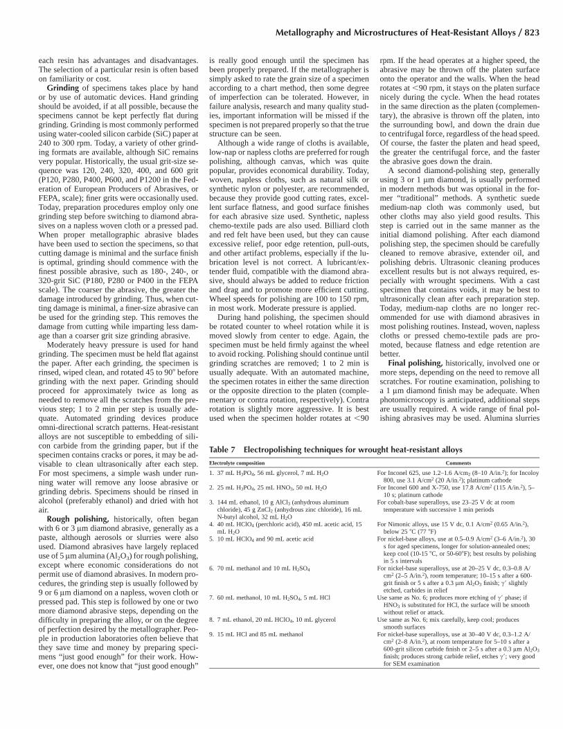
different locations, etched with glyceregia versusa Beraha-type color etch (20 mL HCl, 100 mLwater, 0.5 g K2S2O5, 1 g NH4F•HF). Figure 11shows the grain structure of solution annealedand aged Pyromet 31, an iron-nickel superalloyetched with waterless Kalling’s and with a Ber-aha-type color etch (66 mL HCl, 33 mL water,1 g K2S2O5). Figure 12 shows the grain structureof alloy X-750, a nickel-base superalloy in thesolution annealed and aged condition etchedwith glyceregia, waterless Kalling’s, Marble’sreagent, aqua regia, HCl � 1% Na2O2, and aBeraha tint etch (50 mL HCl, 50 mL water, 1 gK2S2O5). Figures 13 to 15 show the grain struc-ture of Waspaloy, a nickel-base superalloy, in thesolution annealed (1010, 1035, and 1065 �C, or1850, 1900, and 1950 �F) and aged conditions,etched with glyceregia and with a Beraha-typecolor etchant (50 mL HCl, 50 mL water, 1 gK2S2O5). In each of these examples, the color
Fig. 10 Alloy A-286 (AISI 660, 318 HV), solution annealed 1 h at 980 �C (1800 �F), oil quenched, aged 16 h at 720�C (1325 �F), and air cooled. (a) Glyceregia. (b) Tint etched. Only the matrix phase has been colored. 20 mL
HCl, 100 mL H2O, 1 g NH4F•HF, and 0.5 g K2S2O5. Original magnification, both 100�
Fig. 11 Pyromet 31 (40 HRC), solution annealed and aged. (a) Etched using Kalling’s reagent 2 (waterless Kalling’s).(b) Tint etched with 66 mL HCl, 33 mL H2O, and 1 g K2S2O5. Original magnification, both 100�
828 / Metallography and Microstructures of Nonferrous Alloys
etch revealed the grain structure with strong con-trast.
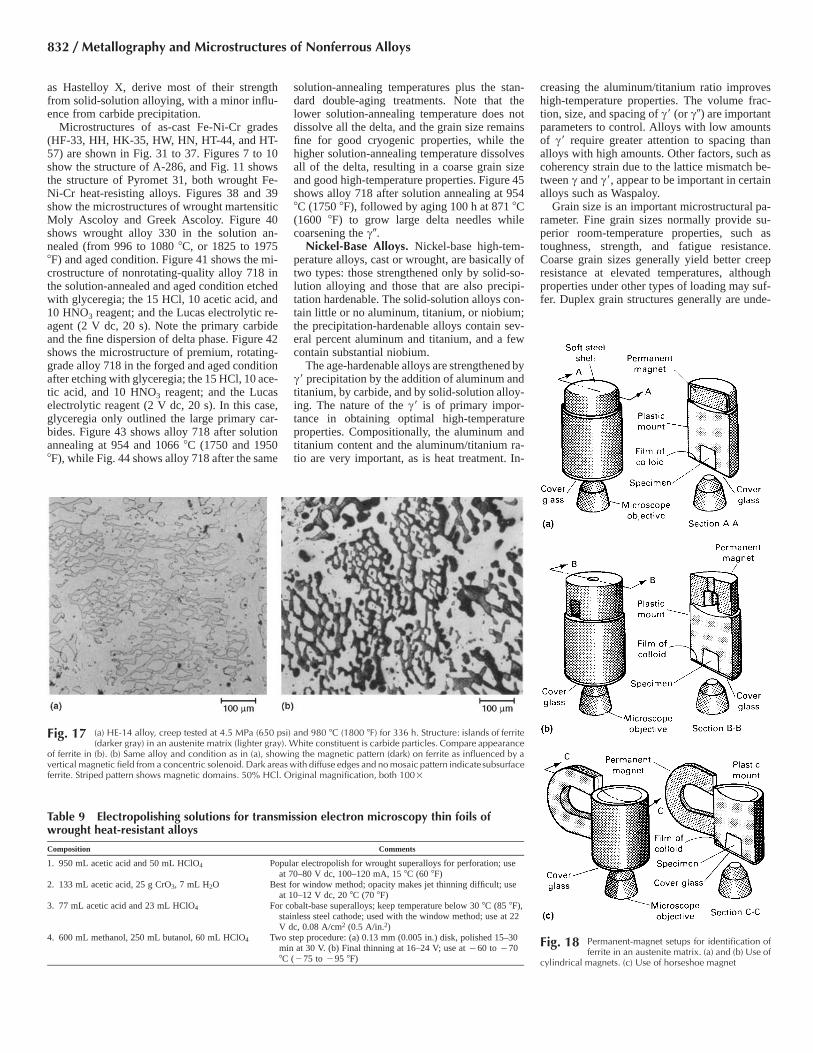
Identification of Ferrite by Magnetic Etch-ing. Because of the low contrast, or lack of con-trast, after etching, it is sometimes difficult todifferentiate ferrite contained in an austenite ma-trix. A technique using a magnetic field andmagnetic particles (smaller than 30 nm) in anorganic or an aqueous colloidal suspension canbe used in conjunction with the light optical mi-croscope to identify ferrite positively (Ref 20–24). Details of the magnetic technique are de-scribed as follows. Additional information canbe found in the article “Contrast Enhancementand Etching” in this Volume.
A drop (5 lL measured in a micropipette) ofthe suspension is deposited on the surface of aspecimen that has been polished and lightlyetched with HCl. A thin cover is placed over thesuspension. If the specimen is contained in a 25mm (1 in.) diameter plastic mount, a cover glassof the same diameter is ideal. The specimen isplaced on an inverted metallographic micro-scope. When the specimen is face down, its
weight plus the spring pressure applied will presson the suspension under the glass, keeping it thinand relatively uniform in thickness.
An electromagnet or a permanent magnet canbe used to apply a magnetic field to the speci-men. If an electromagnet is used for applying themagnetic field, it is a solenoid placed around thespecimen, as shown in Fig. 16. It has a windingof 2300 A turn and operates on batteries or ondirect current rectified from alternating current.The field can be cut off or reversed readily usingswitches. A variable autotransformer betweenthe line and rectifier input or a rheostat in serieswith a battery source controls the intensity of themagnetizing field. The magnetic field will causea visible concentration of the colloid particlesover the magnetic areas. Figure 17(b) shows themagnetic pattern produced. Comparison of Fig.17(b) with Fig. 17(a) shows that the magneticpattern identifies the ferrite in the specimen.
For cursory ferrite identification, it is simplerto use a permanent magnet. Various shapes areavailable. A cylindrical Alnico permanent mag-net can be placed on top of the inverted speci-
men, as shown in Fig. 18(a) and (b), or an Alnicohorseshoe magnet can be placed alongside, asshown in Fig. 18(c). The horseshoe magnet pro-vides a horizontal and a vertical field. The fieldis most intense through that part of the specimenclosest to the pole pieces of the magnet.
Transmission Electron Microscopy. Be-cause some of the important constituents inwrought heat-resistant alloys, such as c� phase,are generally too small to observe using the lightoptical microscope, considerable use has beenmade of TEM. Besides affording greater reso-lution and higher magnification, TEM providesmeans for phase identification by electron dif-fraction and, when equipped with x-ray detec-tors, can provide chemical analysis data. Suchanalytical procedures are necessary to under-stand the strengthening mechanisms for heat-re-sistant alloys. Today, field emission SEMs pro-vide enough resolution to examine the c�particles in nearly all wrought superalloys. Thec� in cast heat-resistant alloys is coarser than inwrought alloys and easier to study. Electron-backscattered diffraction can provide a useful al-
Fig. 12 The effects of different etchants on solution-annealed and aged alloy X-750. (a) Etched using glyceregia. Original magnification 100�. (b) Etched using Kalling’s reagent 2.Original magnification 100�. (c) Etched using Marble’s reagent. 100�. (d) Etched using aqua regia. 100� (e) Etched using HCl � 1% Na2O2. Original magnification
100�. (f ) Tint etched in 50 mL HCl, 50 mL H2O, and 1 g K2S2O5
Metallography and Microstructures of Heat-Resistant Alloys / 829

ternative to the more tedious convergent-beamelectron diffraction with the TEM for identifi-cation of the crystal structure of phases. Energy-dispersive spectroscopy provides chemical in-formation and can be used with either the SEMor the TEM.
Several types of specimens can be preparedfor TEM examination; each type has advantagesand disadvantages. The replica method, whichhad been prevalent, is being replaced by use ofthe SEM (Ref 17, 18). A well-polished and prop-erly etched specimen can be examined with astandard SEM at magnifications of 50,000� ormore. Therefore, much of the structural exami-nation role of TEM replicas can be accomplishedwithout replica preparation and the complicationof replica interpretation or artifact control.
In addition, the contrast mechanisms operablein the SEM are valuable for structural exami-nation. Because chemical analysis using SEM islimited to features larger than a few microns,TEM examination and analysis of extracted con-stituents remains an important procedure. Pro-cedures for preparing structural and extractionreplicas are discussed in Ref 25 to 33. Directexamination of the fine structure of heat-resistantalloys is also performed by TEM examination ofthin foils. As with extraction replicas, electrondiffraction and chemical analysis can be per-formed.
Because the beam size in a transmission elec-tron microscope or a scanning transmission mi-croscope is much smaller than in a scanningelectron microscope, much finer particles can beanalyzed using thin foils without interferencefrom the surrounding matrix. Extremely smallparticles are difficult to analyze even with atransmission electron microscope. Extractionreplicas are useful, because matrix effects can beeliminated. In addition, using a transmissionelectron microscope, microdiffraction patternsare obtainable from individual particles ratherthan many particles. The microdiffraction pat-tern is of great value in basic structural studiesof the constituents.
Thin foils are prepared by the window methodor the disk method described in Ref 25 to 27 and33 to 36. These methods involve careful section-ing to obtain a relatively thin slice of the materialfree of artifacts, followed by mechanical, chem-ical, or electrolytic thinning until a small area isthin enough for electron transmission. Table 9lists several popular electropolishing proceduresfor preparing thin foils of heat-resistant alloys.
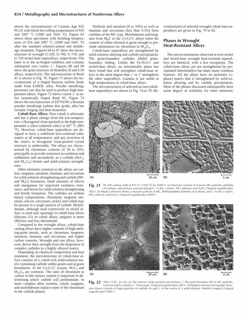
Figure 19 shows the microstructure of cast B-1900 nickel-base alloy containing carbides andcoarse c� precipitates in a c matrix revealed bylight microscopy and with a replica viewed withthe TEM. The large angular particle in the centerof Fig. 19(c) is an MC carbide, while the c� isfiner in size and in high concentration. Similarexamples are given in Fig. 20 and 21 for cast IN-100 and in Fig. 22 for alloy 713C, both nickel-base alloys. Figure 23 shows coarse c� in castIN-738 alloy where the shape is basically cubi-cal. However, after solution annealing (1120 �C,or 2050 �F, for 2 h) and aging 24 h at 845 �C
(1550 �F), the c� is finer and spherical in shapewith two different sizes, as shown in Fig. 24. Ifan IN-738 casting is aged at 815 �C (1500 �F)for 1000 h, the c� is spherical with a single sizedistribution (Fig. 25). Other shapes and phasescan be observed in cast superalloys, as illustratedin Fig. 26. This shows light optical and TEMviews of a MAR-M 246 casting held at 980 �C(1800 �F) for 5000 h. There is needlelike M6Ccarbide and c� in the matrix. In this case, the c�is not uniform in shape. Figure 27 shows an ex-ample of the structural changes in cast MAR-M246 heated above 980 �C (1800 �F). Comparethese micrographs to those in Fig. 26.
Transmission electron microscopy examina-tion is also crucial in the examination of the finestrengthening phases in wrought alloys. Figure28 shows light optical and TEM views of the
grain structure of Astroloy and c� in a specimensolution annealed 1 h at 1150 �C (2100 �F). Thec� is fine and spherical. Figure 29 shows thesame nickel-base alloy, Astroloy, solution an-nealed 4 h at 1150 �C (2100 �F), air cooled, aged4 h at 1080 �C (1975 �F), oil quenched, aged 4h at 845 �C (1550 �F), air cooled, aged 16 h at760 �C (1400 �F), and air cooled. Light micros-copy reveals grain-boundary MC carbides andcoarse c�, while the TEM replica reveals irreg-ularly shaped c� in the grain boundaries and twosizes of c� from the aging treatments at 845 and760 �C (1550 and 1400 �F). Figure 30 showsdifferences in c� precipitation in alloy X-750. InFig. 30(a), the specimen was solution annealedat 1150 �C (2100 �F) for 2 h, air cooled, thenaged 24 h at 815 �C (1500 �F). The c� is smalland uniformly dispersed. M23C6 carbide can be
Fig. 13 Waspaloy (42 HRC), solution annealed 4 h at 1010 �C (1850 �F), water quenched, aged 4 h at 845 �C (1550�F), air cooled, aged 16 h at 760 �C (1400 �F), and air cooled. (a) Glyceregia. Original magnification 200�.
(b) Tint etched to color matrix phase. 50 mL HCl, 50 mL H2O, and 1 g K2S2O5. Original magnification 100�
Fig. 14 Waspaloy (37 HRC), solution annealed 4 h at 1035 �C (1900 �F), water quenched, aged 4 h at 845 �C (1550�F), air cooled, aged 16 h at 760 �C (1400 �F), and air cooled. (a) Etched in glyceregia. (b) Tint etched in 50
mL HCl, 50 mL H2O, and 1 g K2S2O5. Original magnification, both 100�
830 / Metallography and Microstructures of Nonferrous Alloys

seen in the grain boundary. In Fig. 30(b), thespecimen was given the same solution anneal,but it was double aged, first at 845 �C (1550 �F)for 24 h and then at 705 �C (1300 �F) for 24 h.The grain-boundary M23C6 carbide is stabilized,and there is a denser precipitation of c� in thematrix.
Bulk Extractions. X-ray diffraction studies ofphases extracted electrolytically are widely prac-ticed. X-ray diffraction is an important tool forphase identification in heat-resistant alloys (Ref37–45). Because of the complex nature of thesealloys, such techniques must be carefully con-trolled to ensure good results. Qualitative iden-tification of the phases by this method is consid-erably easier than quantitative evaluations. Theextraction method must be designed to permitseparation of the carbides, nitrides, c�, and top-ologically close-packed (tcp) phases. Once sepa-rated, the phases can be analyzed using x-raydiffraction, chemical analysis (elemental), andlight and electron microscopy procedures.
Considerable research has been conducted toestablish reliable procedures for bulk extractionin heat-resistant alloys (Ref 37–45). Anodic dis-solution using 10% HCl in methanol, which dis-solves c� and the austenitic matrix, is imple-mented to extract carbides, borides, nitrides, andtcp phases. If the alloy to be digested containssubstantial amounts of tungsten, tantalum, or ni-obium, 1% tartaric acid is added to prevent con-tamination of the residue.
To extract c� from nickel-base alloys, twoelectrolytes have been used: 20% aqueous phos-phoric acid (H3PO4), or an aqueous solution con-taining 1% ammonium sulfate [(NH4)2SO4] and1% citric acid or tartaric acid. The latter electro-lyte produces better recovery of c�. When theammonium sulfate/citric or tartaric acid electro-lyte is used, the residue will also contain car-bides, nitrides, and borides (if present in the al-loy). All the c� morphologies are extracted usingthis electrolyte. Details concerning the use ofthese electrolytes and others are given in Table10 and provided in Ref 37 to 45.
Microstructures ofHeat-Resistant Alloys
Heat-resistant alloys are designed for useabove approximately 540 �C (1000 �F). In gen-eral, they have an austenitic (c-phase) matrix andcontain a wide variety of secondary phases. Themost common second phases are metal carbides(MC, M23C6, M6C, and M7C3) and c�, the or-dered face-centered cubic strengthening phase[Ni3(Al, Ti)] found in age-hardenable Fe-Ni-Crand nickel-base superalloys. In age-hardenablealloys containing niobium or niobium and tan-talum, the primary strengthening phase is c�, abody-centered tetragonal phase. Other phases,generally undesirable, may be observed due tovariations in composition or processing or dueto high-temperature exposure. Included in thisgroup are orthorhombic d phase (Ni3Nb), r
phase, Laves, and the hexagonal close-packed gphase (Ni3Ti). Nitrides are also commonly ob-served, and borides may be present in some al-loys.
The physical metallurgy of these systems isquite complex, perhaps more challenging thanthat of any other commercial alloy system. Inaddition, as demonstrated in Tables 1 to 3, thecompositions of these alloys are complex aswell. References 46 to 57 provide basic reviewarticles on the metallography and physical met-allurgy of these alloys. Table 11 summarizes thefunctions of elements in heat-resistant alloys. Ingeneral, the Fe-Ni-Cr-base alloys tend towardformation of tcp phases, such as r, l, Laves, andv phase. The nickel-base alloys are prone to pre-cipitation of ordered geometrically close-packedphases, such as c� and g. Such phases are notcommon in cobalt-base alloys, because c� is nota suitable strengthening agent. The cobalt-basealloys contain various carbides, nitrides, r, andl, depending on composition, processing, andexposure conditions.
Iron-Nickel-Chromium-Base Alloys. Manycast and wrought Fe-Ni-Cr-base heat-resistantalloys (the wrought alloys are usually classifiedas iron-nickel-base, even though they all containsubstantial chromium) have been developed.These alloys contain at least 10% Fe but gener-ally 18 to approximately 55%. The cast Fe-Ni-Cr alloys are not strengthened by c�. The mostimportant of the wrought Fe-Ni-Cr-base alloysare those with an austenitic matrix that arestrengthened by c�, such as A-286. Some ofthese alloys are quite similar to wrought austen-itic stainless steels with the addition of the c�strengthening agent; therefore, metallographicprocedures for these alloys are identical to thosefor wrought austenitic stainless steels. Other Fe-Ni-Cr-base alloys, such as Inconel 718, containmuch less iron and additions of niobium and tan-talum to obtain strengthening from c�. Anothergroup of Fe-Ni-Cr-base alloys contains ratherhigh carbon contents and is strengthened by car-bides, nitrides, carbonitrides, and solid-solutionstrengthening. Other Fe-Ni-Cr-base alloys, such
Fig. 15 Waspaloy (35 to 36 HRC), solution annealed 4 h at 1065 �C 1950 �F), water quenched, aged 4 h at 845 �C(1550 �F), air cooled, aged 16 h at 760 �C (1400 �F), and air cooled. (a) Etched in glyceregia. (b) Tint etched
using 50 mL HCl, 50 mL H2O, 3 g NH4F•HF, and 1.5 g K2S2O5. Original magnification, both 100�
Fig. 16 Electromagnet setup for identification of ferrite in Fe-Cr-Ni alloys
Metallography and Microstructures of Heat-Resistant Alloys / 831
as Hastelloy X, derive most of their strengthfrom solid-solution alloying, with a minor influ-ence from carbide precipitation.
Microstructures of as-cast Fe-Ni-Cr grades(HF-33, HH, HK-35, HW, HN, HT-44, and HT-57) are shown in Fig. 31 to 37. Figures 7 to 10show the structure of A-286, and Fig. 11 showsthe structure of Pyromet 31, both wrought Fe-Ni-Cr heat-resisting alloys. Figures 38 and 39show the microstructures of wrought martensiticMoly Ascoloy and Greek Ascoloy. Figure 40shows wrought alloy 330 in the solution an-nealed (from 996 to 1080 �C, or 1825 to 1975�F) and aged condition. Figure 41 shows the mi-crostructure of nonrotating-quality alloy 718 inthe solution-annealed and aged condition etchedwith glyceregia; the 15 HCl, 10 acetic acid, and10 HNO3 reagent; and the Lucas electrolytic re-agent (2 V dc, 20 s). Note the primary carbideand the fine dispersion of delta phase. Figure 42shows the microstructure of premium, rotating-grade alloy 718 in the forged and aged conditionafter etching with glyceregia; the 15 HCl, 10 ace-tic acid, and 10 HNO3 reagent; and the Lucaselectrolytic reagent (2 V dc, 20 s). In this case,glyceregia only outlined the large primary car-bides. Figure 43 shows alloy 718 after solutionannealing at 954 and 1066 �C (1750 and 1950�F), while Fig. 44 shows alloy 718 after the same
solution-annealing temperatures plus the stan-dard double-aging treatments. Note that thelower solution-annealing temperature does notdissolve all the delta, and the grain size remainsfine for good cryogenic properties, while thehigher solution-annealing temperature dissolvesall of the delta, resulting in a coarse grain sizeand good high-temperature properties. Figure 45shows alloy 718 after solution annealing at 954�C (1750 �F), followed by aging 100 h at 871 �C(1600 �F) to grow large delta needles whilecoarsening the c�.
Nickel-Base Alloys. Nickel-base high-tem-perature alloys, cast or wrought, are basically oftwo types: those strengthened only by solid-so-lution alloying and those that are also precipi-tation hardenable. The solid-solution alloys con-tain little or no aluminum, titanium, or niobium;the precipitation-hardenable alloys contain sev-eral percent aluminum and titanium, and a fewcontain substantial niobium.
The age-hardenable alloys are strengthened byc� precipitation by the addition of aluminum andtitanium, by carbide, and by solid-solution alloy-ing. The nature of the c� is of primary impor-tance in obtaining optimal high-temperatureproperties. Compositionally, the aluminum andtitanium content and the aluminum/titanium ra-tio are very important, as is heat treatment. In-
creasing the aluminum/titanium ratio improveshigh-temperature properties. The volume frac-tion, size, and spacing of c� (or c�) are importantparameters to control. Alloys with low amountsof c� require greater attention to spacing thanalloys with high amounts. Other factors, such ascoherency strain due to the lattice mismatch be-tween c and c�, appear to be important in certainalloys such as Waspaloy.
Grain size is an important microstructural pa-rameter. Fine grain sizes normally provide su-perior room-temperature properties, such astoughness, strength, and fatigue resistance.Coarse grain sizes generally yield better creepresistance at elevated temperatures, althoughproperties under other types of loading may suf-fer. Duplex grain structures generally are unde-
Fig. 17 (a) HE-14 alloy, creep tested at 4.5 MPa (650 psi) and 980 �C (1800 �F) for 336 h. Structure: islands of ferrite(darker gray) in an austenite matrix (lighter gray). White constituent is carbide particles. Compare appearance
of ferrite in (b). (b) Same alloy and condition as in (a), showing the magnetic pattern (dark) on ferrite as influenced by avertical magnetic field from a concentric solenoid. Dark areas with diffuse edges and no mosaic pattern indicatesubsurfaceferrite. Striped pattern shows magnetic domains. 50% HCl. Original magnification, both 100�
Fig. 18 Permanent-magnet setups for identification offerrite in an austenite matrix. (a) and (b) Use of
cylindrical magnets. (c) Use of horseshoe magnet
Table 9 Electropolishing solutions for transmission electron microscopy thin foils ofwrought heat-resistant alloys
Composition Comments
1. 950 mL acetic acid and 50 mL HClO4 Popular electropolish for wrought superalloys for perforation; useat 70–80 V dc, 100–120 mA, 15 �C (60 �F)
2. 133 mL acetic acid, 25 g CrO3, 7 mL H2O Best for window method; opacity makes jet thinning difficult; useat 10–12 V dc, 20 �C (70 �F)
3. 77 mL acetic acid and 23 mL HClO4 For cobalt-base superalloys; keep temperature below 30 �C (85 �F),stainless steel cathode; used with the window method; use at 22V dc, 0.08 A/cm2 (0.5 A/in.2)
4. 600 mL methanol, 250 mL butanol, 60 mL HClO4 Two step procedure: (a) 0.13 mm (0.005 in.) disk, polished 15–30min at 30 V. (b) Final thinning at 16–24 V; use at �60 to �70�C (�75 to �95 �F)
832 / Metallography and Microstructures of Nonferrous Alloys

sirable. Grain size also affects carbide precipi-tation at the grain boundaries. Coarse grain sizeshave less grain-boundary surface area; therefore,carbide precipitation will be more continuousand thicker, thus impairing properties. Due tothese problems, a uniform, intermediate grainsize is generally preferred.
Microstructures of cast nickel-base alloys IN-738, MAR-M 247, and CNK7 were shown inFig. 3 to 5. Microstructures of other cast grades(Hastelloy B and C, IN-100, 713C, MAR-M246, TRW-NASA VI A, and U-700) are shown
in Fig. 46 to 53. The use of different etchants toreveal the microstructure of wrought X-750 andWaspaloy were given in Fig. 12 to 15. Figure 54shows Waspaloy in the as-forged condition; Fig.55 shows the grain structure of rotating-gradeWaspaloy in the solution-annealed and aged con-dition (grains are still elongated from forging),while Fig. 56 shows the grain structure of rotat-ing-grade Waspaloy in the solution-annealed andaged condition (note the duplex, necklace-typegrain structure). Figure 57 shows the grain struc-ture of Russian wrought alloy ZMI-3U after
39,000 h of service (forged turbine blade). Fig-ure 58 shows the microstructure at the center ofan as-forged 30.5 cm (12 in.) diameter bar ofalloy 600; note the grain-boundary carbides.
Figure 59 shows the grain structure of alloy617 strip. Note the fine carbides strung out in therolling direction. Figure 60 shows the carbidesin alloy 625 after solution annealing at 982 �C(1800 �F) (as-polished condition, revealed by in-troducing a slight amount of relief in final pol-ishing). Figure 61 shows the microstructure ofas-forged Custom Age 625 PLUS. Figure 62
Fig. 19 B-1900 nickel-base alloy, as-cast. (a) Structure consists of nickel-rich c solid-solution matrix containing a few light-etching carbide particles and dispersed c�. Kalling’sreagent. Original magnification 100� (b) Higher magnification. The light-etching carbide particles are dispersed and at grain boundaries. The fine constituent within grains
is c�. Kalling’s reagent 2. Original magnification 500�. (c) Higher magnification and a replica electron micrograph showing details of a large MC carbide particle and particles of c�in the c matrix. HCl, ethanol, CuCl2, and H2O2. Original magnification 7500�
Fig. 20 IN-100, as-cast. (a) Small, white islands are primary (eutectic) c�; peppery gray constituent is precipitated c�; black constituent is probably perovskite, a complex carbide.Ni3(Al,Ti)C; matrix is nickel-rich c. Marble’s reagent. Original magnification 100�. (b) Higher magnification. Light constituent (A) is primary (eutectic) c�; dark (B), probably
perovskite, Ni3(Al,Ti)C. Dispersed carbide particles are shown at C. Gamma matrix contains precipitated c� (D). Marble’s reagent. Original magnification 500�. (c) Higher magnificationand a replica electron micrograph showing islands of primary c� (A), a large particle of primary carbide (B), and dispersed particles of precipitated c� in c matrix. Marble’s reagent.Original magnification 5000�
Metallography and Microstructures of Heat-Resistant Alloys / 833
shows the microstructure of Custom Age 625PLUS with finish hot rolling temperatures of 916and 1007 �C (1680 and 1845 �F). Figure 63shows these specimens with finishing tempera-tures of 916 and 1007 �C (1680 and 1845 �F)after the standard solution-anneal and double-age treatment. Figures 64 to 67 show the micro-structure of wrought U-520, U-700, U-710, andU-720 nickel-base superalloys, respectively. Thelatter is in the as-forged condition and containssubstantial very coarse c�. Figures 68 and 69show the grain structure of Hastelloy B and G30alloys, respectively. The microstructure of Rene41 is shown in Fig. 70. Figure 71 shows the mi-crostructure of a forged Russian turbine blademade from E1893L alloy. Powder metallurgyprocesses can also be used to produce high-tem-perature alloys. Figure 72 shows coarse c� in as-hot isostatically forged Rene 95. Figure 73shows the microstructure of EP741NP, a Russianpowder metallurgy turbine disc grade, after hotisostatic forging and heat treatment.
Cobalt-Base Alloys. Pure cobalt is allotropicand has a phase change from the low-tempera-ture e (hexagonal close-packed) to the high-tem-perature � (face-centered cubic) at 427 �C (801�F). However, cobalt-base superalloys are de-signed to have a stabilized face-centered cubicmatrix at all temperatures, and any reversion ofthe matrix to hexagonal close-packed crystalstructure is undesirable. The alloys are charac-terized by chromium contents of 18 to 35%,principally to provide resistance to oxidation andsulfidation and secondarily as a carbide (M7C3
and M23C6) former and solid-solution strength-ener.
Other elements common to the alloys are car-bon, tungsten, tantalum, titanium, and zirconiumfor solid-solution strengthening and carbide (MCand M6C) formation, small amounts of siliconand manganese for improved oxidation resis-tance, and boron for solid-solution strengtheningand boride formation. The carbides are seldombinary compositions; chromium, tungsten, tan-talum, silicon, zirconium, nickel, and cobalt maybe present in a single particle of carbide. Molyb-denum, although used extensively in nickel al-loys, is used only sparingly in cobalt-base alloys(Haynes 21); in cobalt alloys, tungsten is moreeffective and less detrimental.
Compared to the wrought alloys, cobalt-basecasting alloys have higher contents of high-melt-ing-point metals, such as chromium, tungsten,tantalum, titanium, and zirconium, and highercarbon contents. Wrought and cast alloys, how-ever, derive their strength from the dispersion ofcomplex carbides in a highly alloyed matrix.
Depending on chemical composition and heattreatment, the microstructure of cobalt-base al-loys consists of a cobalt-rich solid-solution ma-trix containing carbide within grains and at grainboundaries. In the Co-Cr-C system, M7C3 andM23C6 are common. The ratio of chromium tocarbon in this ternary system is important in de-termining which carbide will predominate. Inmore complex alloy systems, cobalt, tungsten,and molybdenum replace some of the chromiumin the carbide phases.
Niobium and tantalum (8 to 10%) as well astitanium and zirconium (less than 0.5%) formcarbides of the MC type. Molybdenum and tung-sten form M6C in the Co-Cr-C alloys when thecontent of either element is great enough to pre-clude substitution for chromium in M23C6.
Cobalt-base superalloys are strengthened bysolid-solution alloying and carbide precipitation.The grain-boundary carbides inhibit grain-boundary sliding. Unlike the Fe-Ni-Cr- andnickel-base alloys, no intermetallic phase hasbeen found that will strengthen cobalt-base al-loys to the same degree that c� or c� strengthensthe other superalloys. Gamma is not stable athigh temperatures in cobalt-base alloys.
The microstructures of selected as-cast cobalt-base superalloys are shown in Fig. 74 to 78. Mi-
crostructures of selected wrought cobalt-base su-peralloys are given in Fig. 79 to 82.
Phases in WroughtHeat-Resistant Alloys
The microconstituents observed in iron-nickeland nickel-base wrought heat-resistant superal-loys are identical, with a few exceptions. Thecobalt-base alloys are not strengthened by pre-cipitated intermetallics but share many commonfeatures. All the alloys have an austenitic (c-phase) matrix that is strengthened by solid-so-lution alloying and by carbide precipitation.Most of the phases discussed subsequently havesome degree of solubility for other elements;
Fig. 21 IN-100 casting, held at 815 �C (1500 �F) for 5000 h. (a) Structure consists of massive MC particles, plateletsof r phase, and primary and precipitated c� in the c matrix. HCl, ethanol, and H2O2. Original magnification
500� (b) Replica electron shows a massive particle of MC, Widmanstatten platelets of r phase, and c� in the c matrix.HCl, ethanol, and H2O2. Original magnification 4500�
Fig. 22 Alloy 713C, as-cast. (a) The massive white particles are primary c�; the grain-boundary film is MC particles.Gamma matrix contains c�. Glyceregia. Original magnification 500�. (b) Replica electron micrograph. Struc-
ture shown consists of large particles of carbide (A) and c� in the matrix of c solid solution. Marble’s reagent. Originalmagnification 5000�
834 / Metallography and Microstructures of Nonferrous Alloys
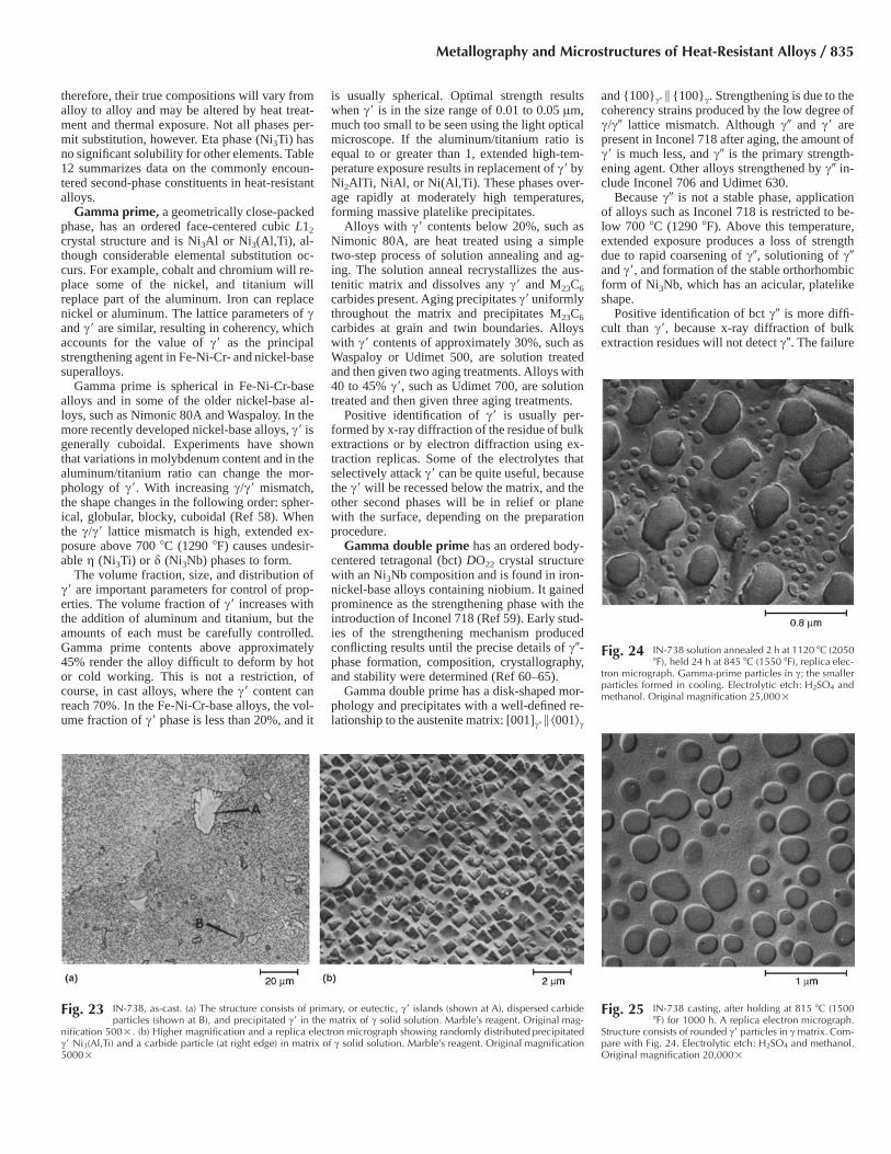
therefore, their true compositions will vary fromalloy to alloy and may be altered by heat treat-ment and thermal exposure. Not all phases per-mit substitution, however. Eta phase (Ni3Ti) hasno significant solubility for other elements. Table12 summarizes data on the commonly encoun-tered second-phase constituents in heat-resistantalloys.
Gamma prime, a geometrically close-packedphase, has an ordered face-centered cubic L12
crystal structure and is Ni3Al or Ni3(Al,Ti), al-though considerable elemental substitution oc-curs. For example, cobalt and chromium will re-place some of the nickel, and titanium willreplace part of the aluminum. Iron can replacenickel or aluminum. The lattice parameters of cand c� are similar, resulting in coherency, whichaccounts for the value of c� as the principalstrengthening agent in Fe-Ni-Cr- and nickel-basesuperalloys.
Gamma prime is spherical in Fe-Ni-Cr-basealloys and in some of the older nickel-base al-loys, such as Nimonic 80A and Waspaloy. In themore recently developed nickel-base alloys, c� isgenerally cuboidal. Experiments have shownthat variations in molybdenum content and in thealuminum/titanium ratio can change the mor-phology of c�. With increasing c/c� mismatch,the shape changes in the following order: spher-ical, globular, blocky, cuboidal (Ref 58). Whenthe c/c� lattice mismatch is high, extended ex-posure above 700 �C (1290 �F) causes undesir-able g (Ni3Ti) or d (Ni3Nb) phases to form.
The volume fraction, size, and distribution ofc� are important parameters for control of prop-erties. The volume fraction of c� increases withthe addition of aluminum and titanium, but theamounts of each must be carefully controlled.Gamma prime contents above approximately45% render the alloy difficult to deform by hotor cold working. This is not a restriction, ofcourse, in cast alloys, where the c� content canreach 70%. In the Fe-Ni-Cr-base alloys, the vol-ume fraction of c� phase is less than 20%, and it
is usually spherical. Optimal strength resultswhen c� is in the size range of 0.01 to 0.05 lm,much too small to be seen using the light opticalmicroscope. If the aluminum/titanium ratio isequal to or greater than 1, extended high-tem-perature exposure results in replacement of c� byNi2AlTi, NiAl, or Ni(Al,Ti). These phases over-age rapidly at moderately high temperatures,forming massive platelike precipitates.
Alloys with c� contents below 20%, such asNimonic 80A, are heat treated using a simpletwo-step process of solution annealing and ag-ing. The solution anneal recrystallizes the aus-tenitic matrix and dissolves any c� and M23C6
carbides present. Aging precipitates c� uniformlythroughout the matrix and precipitates M23C6
carbides at grain and twin boundaries. Alloyswith c� contents of approximately 30%, such asWaspaloy or Udimet 500, are solution treatedand then given two aging treatments. Alloys with40 to 45% c�, such as Udimet 700, are solutiontreated and then given three aging treatments.
Positive identification of c� is usually per-formed by x-ray diffraction of the residue of bulkextractions or by electron diffraction using ex-traction replicas. Some of the electrolytes thatselectively attack c� can be quite useful, becausethe c� will be recessed below the matrix, and theother second phases will be in relief or planewith the surface, depending on the preparationprocedure.
Gamma double prime has an ordered body-centered tetragonal (bct) DO22 crystal structurewith an Ni3Nb composition and is found in iron-nickel-base alloys containing niobium. It gainedprominence as the strengthening phase with theintroduction of Inconel 718 (Ref 59). Early stud-ies of the strengthening mechanism producedconflicting results until the precise details of c�-phase formation, composition, crystallography,and stability were determined (Ref 60–65).
Gamma double prime has a disk-shaped mor-phology and precipitates with a well-defined re-lationship to the austenite matrix: [001]c� � �001�c
and {100}c� � {100}c. Strengthening is due to thecoherency strains produced by the low degree ofc/c� lattice mismatch. Although c� and c� arepresent in Inconel 718 after aging, the amount ofc� is much less, and c� is the primary strength-ening agent. Other alloys strengthened by c� in-clude Inconel 706 and Udimet 630.
Because c� is not a stable phase, applicationof alloys such as Inconel 718 is restricted to be-low 700 �C (1290 �F). Above this temperature,extended exposure produces a loss of strengthdue to rapid coarsening of c�, solutioning of c�and c�, and formation of the stable orthorhombicform of Ni3Nb, which has an acicular, platelikeshape.
Positive identification of bct c� is more diffi-cult than c�, because x-ray diffraction of bulkextraction residues will not detect c�. The failure
Fig. 23 IN-738, as-cast. (a) The structure consists of primary, or eutectic, c� islands (shown at A), dispersed carbideparticles (shown at B), and precipitated c� in the matrix of c solid solution. Marble’s reagent. Original mag-
nification 500�. (b) Higher magnification and a replica electron micrograph showing randomly distributed precipitatedc� Ni3(Al,Ti) and a carbide particle (at right edge) in matrix of c solid solution. Marble’s reagent. Original magnification5000�
Fig. 24 IN-738 solution annealed 2 h at 1120 �C (2050�F), held 24 h at 845 �C (1550 �F), replica elec-
tron micrograph. Gamma-prime particles in c; the smallerparticles formed in cooling. Electrolytic etch: H2SO4 andmethanol. Original magnification 25,000�
Fig. 25 IN-738 casting, after holding at 815 �C (1500�F) for 1000 h. A replica electron micrograph.
Structure consists of rounded c� particles in c matrix. Com-pare with Fig. 24. Electrolytic etch: H2SO4 and methanol.Original magnification 20,000�
Metallography and Microstructures of Heat-Resistant Alloys / 835
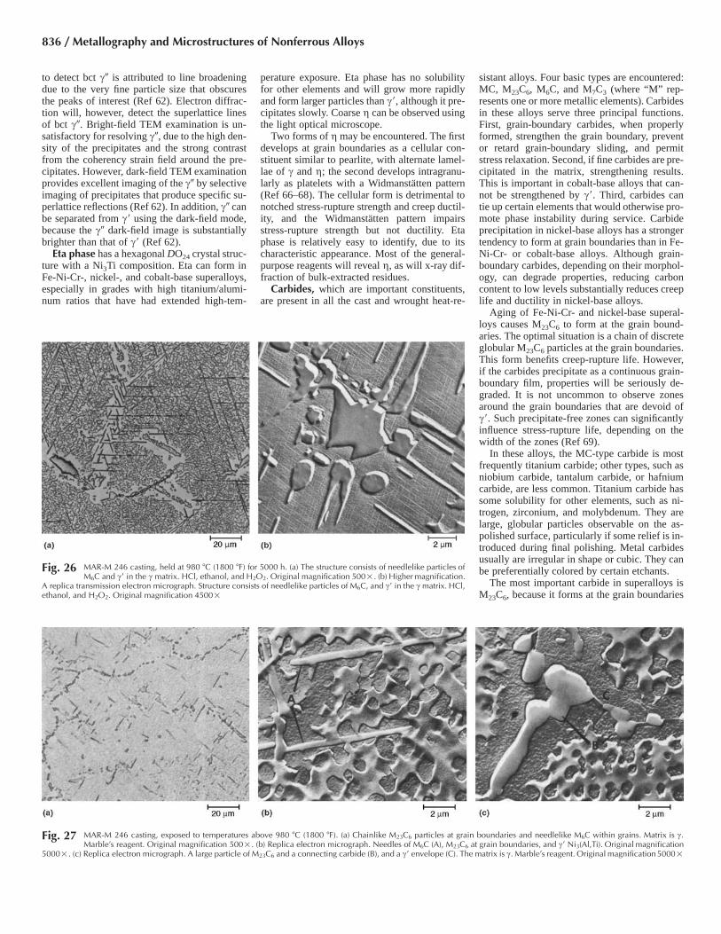
to detect bct c� is attributed to line broadeningdue to the very fine particle size that obscuresthe peaks of interest (Ref 62). Electron diffrac-tion will, however, detect the superlattice linesof bct c�. Bright-field TEM examination is un-satisfactory for resolving c�, due to the high den-sity of the precipitates and the strong contrastfrom the coherency strain field around the pre-cipitates. However, dark-field TEM examinationprovides excellent imaging of the c� by selectiveimaging of precipitates that produce specific su-perlattice reflections (Ref 62). In addition, c� canbe separated from c� using the dark-field mode,because the c� dark-field image is substantiallybrighter than that of c� (Ref 62).
Eta phase has a hexagonal DO24 crystal struc-ture with a Ni3Ti composition. Eta can form inFe-Ni-Cr-, nickel-, and cobalt-base superalloys,especially in grades with high titanium/alumi-num ratios that have had extended high-tem-
perature exposure. Eta phase has no solubilityfor other elements and will grow more rapidlyand form larger particles than c�, although it pre-cipitates slowly. Coarse g can be observed usingthe light optical microscope.
Two forms of g may be encountered. The firstdevelops at grain boundaries as a cellular con-stituent similar to pearlite, with alternate lamel-lae of c and g; the second develops intragranu-larly as platelets with a Widmanstatten pattern(Ref 66–68). The cellular form is detrimental tonotched stress-rupture strength and creep ductil-ity, and the Widmanstatten pattern impairsstress-rupture strength but not ductility. Etaphase is relatively easy to identify, due to itscharacteristic appearance. Most of the general-purpose reagents will reveal g, as will x-ray dif-fraction of bulk-extracted residues.
Carbides, which are important constituents,are present in all the cast and wrought heat-re-
sistant alloys. Four basic types are encountered:MC, M23C6, M6C, and M7C3 (where “M” rep-resents one or more metallic elements). Carbidesin these alloys serve three principal functions.First, grain-boundary carbides, when properlyformed, strengthen the grain boundary, preventor retard grain-boundary sliding, and permitstress relaxation. Second, if fine carbides are pre-cipitated in the matrix, strengthening results.This is important in cobalt-base alloys that can-not be strengthened by c�. Third, carbides cantie up certain elements that would otherwise pro-mote phase instability during service. Carbideprecipitation in nickel-base alloys has a strongertendency to form at grain boundaries than in Fe-Ni-Cr- or cobalt-base alloys. Although grain-boundary carbides, depending on their morphol-ogy, can degrade properties, reducing carboncontent to low levels substantially reduces creeplife and ductility in nickel-base alloys.
Aging of Fe-Ni-Cr- and nickel-base superal-loys causes M23C6 to form at the grain bound-aries. The optimal situation is a chain of discreteglobular M23C6 particles at the grain boundaries.This form benefits creep-rupture life. However,if the carbides precipitate as a continuous grain-boundary film, properties will be seriously de-graded. It is not uncommon to observe zonesaround the grain boundaries that are devoid ofc�. Such precipitate-free zones can significantlyinfluence stress-rupture life, depending on thewidth of the zones (Ref 69).
In these alloys, the MC-type carbide is mostfrequently titanium carbide; other types, such asniobium carbide, tantalum carbide, or hafniumcarbide, are less common. Titanium carbide hassome solubility for other elements, such as ni-trogen, zirconium, and molybdenum. They arelarge, globular particles observable on the as-polished surface, particularly if some relief is in-troduced during final polishing. Metal carbidesusually are irregular in shape or cubic. They canbe preferentially colored by certain etchants.
The most important carbide in superalloys isM23C6, because it forms at the grain boundaries
Fig. 26 MAR-M 246 casting, held at 980 �C (1800 �F) for 5000 h. (a) The structure consists of needlelike particles ofM6C and c� in the c matrix. HCl, ethanol, and H2O2. Original magnification 500�. (b) Higher magnification.
A replica transmission electron micrograph. Structure consists of needlelike particles of M6C, and c� in the c matrix. HCl,ethanol, and H2O2. Original magnification 4500�
Fig. 27 MAR-M 246 casting, exposed to temperatures above 980 �C (1800 �F). (a) Chainlike M23C6 particles at grain boundaries and needlelike M6C within grains. Matrix is c.Marble’s reagent. Original magnification 500�. (b) Replica electron micrograph. Needles of M6C (A), M23C6 at grain boundaries, and c� Ni3(Al,Ti). Original magnification
5000�. (c) Replica electron micrograph. A large particle of M23C6 and a connecting carbide (B), and a c� envelope (C). The matrix is c. Marble’s reagent. Original magnification 5000�
836 / Metallography and Microstructures of Nonferrous Alloys

during aging and, when properly formed, in-creases the strength of the grain boundaries tobalance the matrix strength. Although chromiumis the primary “M” element, other metallic ele-ments, such as nickel, cobalt, iron, molybdenum,and tungsten, can substitute for it. The discreteglobular form is the most desirable morphology;films, platelets, lamellae, and cells have alsobeen observed.
The M6C carbide is generally rich in molyb-denum or tungsten, but other elements, such aschromium, nickel, or cobalt, may substitute forit to some degree. It is the most commonly ob-served carbide in the cobalt-base superalloys andin nickel-base alloys with high molybdenumand/or tungsten contents. In these alloys, M6C isoften observed in the as-cast condition randomlydistributed throughout the matrix. In wrought al-loys, it will usually be dissolved during heatingbefore hot working. It may precipitate at the
grain boundaries in a blocky form or intragran-ularly in a Widmanstatten pattern and can bepreferentially stained by certain etchants.
The Cr7C3 carbide is likely to appear in thehigher-carbon Fe-Cr-Ni cast alloys as spinelikecrystals of roughly hexagonal cross section, fre-quently with a hole in the center. It can be easilystained with Murakami’s reagent. In the alloyswith 0.20 to 0.75% C, the Cr7C3 carbide is likelyto be the eutectic carbide. Although M7C3 is notwidely observed in wrought superalloys, it ispresent in some cobalt-base alloys and in Ni-monic 80A, a Ni-Cr-Ti-Al superalloy, whenheated above 1000 �C (1830 �F). Additions ofsuch elements as cobalt, molybdenum, tungsten,or niobium to nickel-base alloys prevent for-mation of M7C3. Massive Cr7C3 is formed in Ni-monic 80A in the grain boundaries after heatingto 1080 �C (1975 �F). Subsequent aging at 700�C (1290 �F) to precipitate c� impedes precipi-
tation of M23C6 due to the previously formedCr7C3, which generally exhibits a blocky shapewhen present at grain boundaries.
Borides. Boron is added in small amounts tomany heat-resistant alloys to improve stress-rup-ture and creep properties or to retard formationof g phase, which would impair creep strength.Boron retards formation of the cellular grain-boundary form of g but has no influence on theintragranular Widmanstatten g. Consequently,boron influences grain-boundary structures. Bo-ron also reduces the solubility of carbon in aus-tenite, which increases precipitation of finer-sized MC and M23C6 carbides. If the boronaddition is sufficiently high, detrimental borideswill form. Borides are hard and brittle and pre-cipitate at the grain boundaries. Borides are gen-erally of M3B2 composition with a tetragonalstructure (Ref 70). Molybdenum, tantalum, nio-bium, nickel, iron, or vanadium can be “M” ele-ments. The identification of borides in Udimet700 has been documented (Ref 70).
Laves phase, a tcp phase, has a MgZn2 hex-agonal crystal structure with a composition ofthe AB2 type. Typical examples include Fe2Ti,Fe2Nb, and Fe2Mo, but a more general formulais (Fe,Cr,Mn,Si)2(Mo,Ti,Nb). They are mostcommonly observed in the iron-nickel-base al-loys as coarse intergranular particles; intragran-ular precipitation may also occur. Silicon and ni-obium promote formation of Laves phase inalloy 718. Excessive amounts will impair room-temperature tensile ductility; creep properties arenot significantly affected. Laves phases havebeen observed in certain cobalt-base alloys andhave been identified as Co2W, Co2Ti, or Co2Ta.
Sigma phase is a tetragonal intermetallic tcpphase that forms with a wide range of compo-sitions. Sigma is a hard, brittle compound usu-ally formed from ferrite (but sometimes directlyfrom austenite) between approximately 650 �C(1200 �F) and slightly above 870 �C (1600 �F).
Fig. 28 Astroloy forging, solution annealed 1 h at 1150 �C (2100 �F) and air cooled. (a) View showing grain boundariesand fine MC carbides in a c-phase matrix. Kalling’s reagent 2. Original magnification 100�. (b) Replica
electron micrograph showing a clean grain boundary (diagonal). c� precipitate is visible in the c matrix. Electrolytic:H2SO4, H3PO4, and HNO3. Original magnification 10,000�
Fig. 29 Astroloy forging, solution annealed 4 h at 1150 �C (2100 �F), air cooled, aged 4 h at 1080 �C (1975 �F), oil quenched, aged 4 h at 845 �C (1550 �F), air cooled, aged 16 hat 760 �C (1400 �F), and air cooled. (a) Kalling’s reagent 2. Original magnification 100�. (b) Higher magnification. MC carbides are precipitated at grain boundaries; the
solid-solution matrix contains c� particles. Kalling’s reagent 2. Original magnification 1000�. (c) Replica electron micrograph showing intergranular c� precipitated at 1080 �C (1975�F) as well as fine c� precipitated at 845 �C (1550 �F) and 760 �C (1400 �F). Carbide particles are visible at grain boundaries. Electrolytic: H2SO4, H3PO4, and HNO3. Originalmagnification10,000�
Metallography and Microstructures of Heat-Resistant Alloys / 837

It develops most rapidly near 870 �C (1600 �F).The classic sigma-phase compound has an ap-proximate FeCr composition, but in the alloysdiscussed in this article, it has a more complex,variable composition. The addition of siliconpromotes the formation of r, and a ternary com-position of 43Fe43Cr-14Si (at.%) has been sug-gested. Because r imparts ambient-temperaturebrittleness and a loss of creep-rupture strength,its presence is generally undesirable. Variousmorphologies may be encountered, some ofwhich are quite detrimental to properties. How-ever, the presence of r in superalloys is not nec-essarily damaging to properties. Sigma, in theform of plate precipitation, can improve creepproperties.
Considerable effort has been devoted to de-termining how composition influences r-phaseformation, particularly in nickel-base superal-loys. References 71 to 75 present examples ofthe many studies that have been conducted. Thiswork has substantially influenced alloy devel-opment.
Sigma can be preferentially attacked orstained by a number of reagents. However, be-cause of the wide range of alloy compositionsthat may contain r and the variable nature of itscomposition, positive identification by etching isnot always possible. X-ray diffraction of bulkextraction residues is a more reliable technique.Etching procedures are best applied when theycan be tested for response on specimens of thealloy known to contain r phase.
Mu phase is a rhombohedral (triagonal) in-termetallic tcp phase with a W6Fe7 structure (Ref76). In general, it has little influence on proper-ties. Mu precipitates as coarse, irregularlyshaped platelets in a Widmanstatten pattern. Ageneral formula for l is (Fe,Co)7(Mo,W)6.Nickel can substitute for part of the iron or thecobalt.
Nitrides are commonly observed in heat-re-sistant alloys containing titanium or niobium astitanium nitride (most common) or niobium ni-tride. Nitrides are not influenced by heat treat-ment and are insoluble to the melting point. Ni-trides are easily identified in the as-polishedcondition or after etching due to their regular,angular shapes and distinct yellow-to-orangecolor. Nitrides are quite hard and will appear inrelief after polishing. They have some solubilityfor carbon and may be referred to as Ti(C,N),Nb(C,N), and so on. They should not be con-fused with carbonitrides, which are much richerin carbon and lower in nitrogen. Nitrides, oftenduplex, include an embedded phase or a sur-rounding film; this second phase is generally adarker colored nitride containing considerablecarbon. The usual amounts present in superal-loys generally have little influence on properties.
The acicular constituent that occurs near creepfractures in cast Fe-Ni-Cr alloys is likely to bechromium nitride, which originates by diffusionof nitrogen from the atmosphere. The acicularpattern is the result of precipitation on crystal-lographic planes. However, nitrides are not al-ways acicular, and acicular platelets are not nec-essarily nitrides; r phase, and even carbides, can
exhibit an acicular pattern. A frequently encoun-tered lamellar constituent that resembles pearlitehas been identified as an aggregate of austenite
with carbonitrides, chromium nitride, or chro-mium carbide. Etching in Murakami’s reagent atroom temperature for approximately 10 s will
Fig. 30 Replica electron micrograph of Inconel X-750, solution annealed 2 h at 1150 �C (2100 �F) and air cooled. (a)Aged 24 h at 815 �C (1500 �F). Structure is small, uniformly dispersed c� precipitate and large, discontinuous
M23C6 carbide at the grain boundary. (b) Aged 24 h at 845 �C (1550 �F), then 24 h at 705 �C (1300 �F). Grain-boundaryM23C6 carbide is stabilized, and precipitation of fine c� particles has increased. Both glyceregia. Original magnification,both 15,000�
Table 10 Techniques for bulk electrolytic extractions
Solution Comments
1. 10% HCl in methanol For extraction of carbides, borides, topologically close-packed phases, andgeometrically close-packed phases from nickel- and iron-nickel-basealloys; solution may dissolve Ni3Ti; maintain bath at 0–30 �C (32–85 �F);for alloys containing tungsten, niobium, tantalum, or hafnium, add 1%tartaric acid; use 0.05–0.1 A/cm2 (0.33–0.65 A/in.2) for 4 h or longer(additional details in ASTM E 963)
2. 0.5–2% citric acid and (NH4)2SO4 in H2O(1% of each is most common)
Used to extract c� phase in nickel-base Udimet 700; use at 0.03 A/cm2 (0.2A/in.2) for 3 h at room temperature; minor amounts of carbides andborides will also be extracted (additional details in Ref 35–38)
3. 10 or 20% H3PO4 in H2O Used to extract c� in nickel-base alloys; may etch the c� phase, althoughresults have been contradictory
4. 50 mL HNO3, 20 mL HClO4, 1000 mLH2O
For extraction of c� and g in nickel-base superalloys; use at 0.1 A/cm2
(0.65 A/in.2), 25 �C (75 �F)5. 300 g KCl (potassium chloride), 30 g citric
acid, 50 mL HCl, 1000 mL H2OFor extraction of carbides from nickel-base superalloys; use at 0.1 A/cm2
(0.65 A/in.2), 25 �C (75 �F)
Table 11 Role of elements in superalloys
Effect(a) Iron-base Cobalt-base Nickel-base
Solid-solution strengtheners Cr, Mo Nb, Cr, Mo, Ni, W, Ta Co, Cr, Fe, Mo, W, TaFace-centered cubic matrix stabilizers C, W, Ni Ni . . .Carbide form:
MC Ti Ti W, Ta, Ti, Mo, NbM7C3 . . . Cr CrM23C6 Cr Cr Cr, Mo, WM6C Mo Mo, W Mo, W
Carbonitrides: M(CN) C, N C, N C, NPromotes general precipitation of carbides P . . . . . .Forms c� Ni3(Al,Ti) Al, Ni, Ti . . . Al, TiRetards formation of hexagonal g (Ni3Ti) Al, Zr . . . . . .Raises solvus temperature of c� . . . . . . CoHardening precipitates and/or intermetallics Al, Ti, Nb Al, Mo, Ti(b), W, Ta Al, Ti, NbOxidation resistance Cr Al, Cr Al, CrImproves hot corrosion resistance La, Y La, Y, Th La, ThSulfidation resistance Cr Cr CrImproves creep properties B . . . BIncreases rupture strength B B, Zr B(c)Causes grain-boundary segregation . . . . . . B, C, ZrFacilitates working . . . Ni3Ti . . .
(a) Not all these effects necessarily occur in a given alloy. (b) Hardening by precipitation of Ni3Ti also occurs if sufficient nickel is present. (c) Ifpresent in large amounts, borides are formed.
838 / Metallography and Microstructures of Nonferrous Alloys

stain the carbide but not the nitrides or carboni-trides.
Chi phase may be encountered in Fe-Cr-Niheat-resistant casting alloys containing molyb-denum. Chi phase has a composition similar to
that of r phase, coexists with r (Ref 8), and ishard and brittle. Ternary diagrams have been de-veloped at 815 and 900 �C (1500 and 1650 �F)for the Fe-Cr-Mo system that identify v phase ascontaining approximately 18% Cr, 28% Mo, and
54% Fe by weight, approximating Fe3CrMo. Chiphase can be revealed with a brief etch in Vi-lella’s reagent, followed by electrolytic etchingin concentrated NaOH at 1.5 V. Chi phase is firststained light brown, but after approximately 10
Fig. 31 Alloy HF-33. (a) As cast. Austenite matrix contains eutectic carbide chains (at grain boundaries) and scattered carbide particles. Note the patch of lamellar constituent at agrain boundary. The globular inclusions are chiefly sulfide and silicate. (b) Creep-test specimen, a view of the structure at the interior. Traces of fine carbide precipitation
are evident at slip regions in the austenite matrix. (c) Interior of creep-test specimen fractured after 13,690 h at 650 �C (1200 �F) and 110 MPa (16 ksi). Cored structure is more fullydeveloped; eutectic carbide is unchanged. (d) Interior of creep-test specimen fractured after 13,680 h at 760 �C (1400 �F), 41 MPa (6 ksi). Carbide precipitation is more general than inFig. 31(c) (coalescence of precipitates has begun); eutectic carbide is essentially unchanged. (e) Fracture produced after 1210 h at 870 �C (1600 �F) and 28 MPa (4 ksi). Secondary-carbide precipitation throughout, especially near particles of eutectic carbide and dendrite boundaries; some coalescence. Subgrain boundaries are prominent. (f ) Fracture producedafter 13,300 h of 870 �C (1600 �F) and 17 MPa (2.5 ksi). Eutectic and secondary carbides have coalesced to form a nearly continuous network and paths for subsurface oxidation. Somenitride platelets. (g) Same as (f ), but at the interior of the specimen. The cored structure is much less marked than in (d), and the carbide network is less continuous than in (f ). Somecoalescence of carbide has occurred but, again, less than in (f ). All glyceregia. Original magnification, all 250�
Metallography and Microstructures of Heat-Resistant Alloys / 839
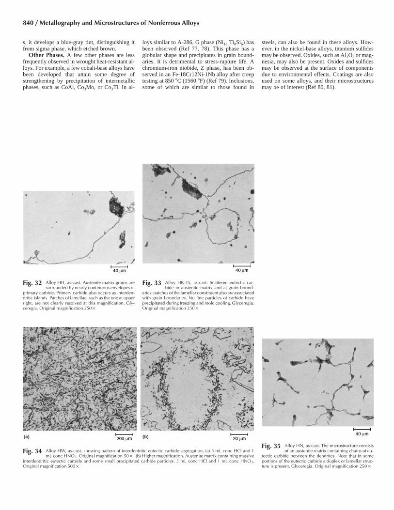
s, it develops a blue-gray tint, distinguishing itfrom sigma phase, which etched brown.
Other Phases. A few other phases are lessfrequently observed in wrought heat-resistant al-loys. For example, a few cobalt-base alloys havebeen developed that attain some degree ofstrengthening by precipitation of intermetallicphases, such as CoAl, Co3Mo, or Co3Ti. In al-
loys similar to A-286, G phase (Ni18 Ti8Si6) hasbeen observed (Ref 77, 78). This phase has aglobular shape and precipitates in grain bound-aries. It is detrimental to stress-rupture life. Achromium-iron niobide, Z phase, has been ob-served in an Fe-18Cr12Ni-1Nb alloy after creeptesting at 850 �C (1560 �F) (Ref 79). Inclusions,some of which are similar to those found in
steels, can also be found in these alloys. How-ever, in the nickel-base alloys, titanium sulfidesmay be observed. Oxides, such as Al2O3 or mag-nesia, may also be present. Oxides and sulfidesmay be observed at the surface of componentsdue to environmental effects. Coatings are alsoused on some alloys, and their microstructuresmay be of interest (Ref 80, 81).
Fig. 32 Alloy HH, as-cast. Austenite matrix grains aresurrounded by nearly continuous envelopes of
primary carbide. Primary carbide also occurs as interden-dritic islands. Patches of lamellae, such as the one at upperright, are not clearly resolved at this magnification. Gly-ceregia. Original magnification 250�
Fig. 33 Alloy HK-35, as-cast. Scattered eutectic car-bide in austenite matrix and at grain bound-
aries; patches of the lamellar constituent also are associatedwith grain boundaries. No fine particles of carbide haveprecipitated during freezing and mold cooling. Glyceregia.Original magnification 250�
Fig. 34 Alloy HW, as-cast, showing pattern of interdentritic eutectic carbide segregation. (a) 5 mL conc HCl and 1mL conc HNO3. Original magnification 50�. (b) Higher magnification. Austenite matrix containing massive
interdendritic eutectic carbide and some small precipitated carbide particles. 5 mL conc HCl and 1 mL conc HNO3.Original magnification 500�
Fig. 35 Alloy HN, as-cast. The microstructure consistsof an austenite matrix containing chains of eu-
tectic carbide between the dendrites. Note that in someportions of the eutectic carbide a duplex or lamellar struc-ture is present. Glyceregia. Original magnification 250�
840 / Metallography and Microstructures of Nonferrous Alloys

Fig. 37 Alloy HT-57, as-cast. This structure is similar tothat shown in Fig. 36 (as-cast alloy HT-44), but
the higher carbon content has caused additional primaryeutectic carbide to form. Also, the larger carbide shapesare coarser than those in Fig. 36. K3Fe(CN)6. Original mag-nification 250�
Fig. 38 Lath martensitic grain structure of Moly Ascoloy (329 HV) revealed using Vilella’s reagent, (a) Original mag-nification 100�. (b) Original magnification 500�
Fig. 39 Lath martensitic grain structure of Greek As-coloy (335 HV) revealed using Vilella’s re-
agent. Original magnification 400�
Fig. 36 Alloy HT-44, as cast. The austenite matrix con-tains a complex network of eutectic carbide
that outlines the boundaries of the original dendrites. Notethat the larger patches of primary carbide have a lamellarstructure. Compare with Fig. 37. K3Fe(CN)6. Original mag-nification 250�
Metallography and Microstructures of Heat-Resistant Alloys / 841

Fig. 40 Austenitic grain structure in alloy 330 revealed using 10% oxalic acid (6 V dc, 10 s) for specimens solution annealed at: (a) 996 �C (1825 �F), (b) 1024 �C (1875 �F), (c)1038 �C (1900 �F), (d) 1052 �C (1925 �F), (e) 1066 �C (1950 �F), and (f ) 1080 �C (1975 �F). Note that only with the 1080 �C (1975 �F) solution anneal is the grain structure
fully recrystallized and of approximately normal size distribution. The specimens were water quenched after solution annealing and aged at 677 �C (1250 �F) for 2 h. Originalmagnification, all 100�
Fig. 41 Grain structure of nonrotating-quality alloy 718, forged and given a standard solution-anneal and aging treatment, revealed using: (a) glyceregia, (b) 15 mL HCl, 10 mLacetic acid, and 10 mL HNO3, and (c) the Lucas electrolytic reagent (2 V dc, 20 s). Note the substantial fine delta content, as well as some large primary carbides. Original
magnification, all 1000�
842 / Metallography and Microstructures of Nonferrous Alloys

Fig. 42 Grain structure of premium-quality alloy 718 in the as-forged and aged condition revealed using different etchants. (a) Glyceregia (it did not reveal the grain or twinboundaries). Original magnification 500�. (b) 15 mL HCl, 10 mL acetic acid, 10 mL HNO3. Original magnification 1000�. (c) The Lucas electrolytic reagent (2 V dc, 20
s). Original magnification 1000�
Fig. 43 Grain structure of hot-rolled alloy 718 in the solution-annealed condition from: (a) 954 �C (1750 �F), and (b)1066 �C (1950 �F). Revealed using glyceregia. This reagent is good for revealing the second-phase precipitates
but is not suitable for fully revealing the grain structure. Note that the lower solution-annealing temperature is used forcryogenic applications (fine grain size), while the higher solution-annealing temperature is used for high-temperatureapplications (coarse grain size). (a) Original magnification 1000�. (b) Original magnification 100�
Fig. 44 Grain structure of hot-rolled alloy 718 in the solution-annealed and double-aged condition (719 �C, or 1326�F, for 8 h, furnace cool to 621 �C (1150 �F), hold 8 h, air cool). Revealed using glyceregia. (a) Solution
annealed at 954 �C (1750 �F). Original magnification 1000�. (b) Solution annealed at 1066 �C (1950 �F). 100�. Notethat delta is present in (a) but not in (b).
Fig. 45 Copious delta phase precipitated along spe-cific crystal planes in specimen of alloy 718
that was solution annealed at 954 �C (1750 �F) and thenaged 100 h at 871 �C (1600 �F). Glyceregia. Original mag-nification 500�
Metallography and Microstructures of Heat-Resistant Alloys / 843
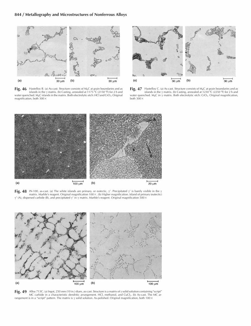
Fig. 46 Hastelloy B. (a) As-cast. Structure consists of M6C at grain boundaries and asislands in the c matrix. (b) Casting, annealed at 1175 �C (2150 �F) for 2 h and
water quenched. M6C islands in the matrix. Both electrolytic etch: HCl and CrO3. Originalmagnification, both 300�
Fig. 47 Hastelloy C. (a) As-cast. Structure consists of M6C at grain boundaries and asislands in the c matrix. (b) Casting, annealed at 1230 �C (2250 �F) for 2 h and
water quenched. M6C in c matrix. Both electrolytic etch: CrO3. Original magnification,both 300�
Fig. 49 Alloy 713C. (a) Ingot, 250 mm (10 in.) diam, as-cast. Structure is a matrix of c solid solution containing“script”MC carbide in a characteristic dendritic arrangement. HCl, methanol, and CuCl2. (b) As-cast. The MC ar-
rangement is in a “script” pattern. The matrix is c solid solution. As-polished. Original magnification, both 100�
Fig. 48 IN-100, as-cast. (a) The white islands are primary, or eutectic, c�. Precipitated c� is barely visible in the cmatrix. Marble’s reagent. Original magnification 100�. (b) Higher magnification. Island of primary (eutectic)
c� (A), dispersed carbide (B), and precipitated c� in c matrix. Marble’s reagent. Original magnification 500�
844 / Metallography and Microstructures of Nonferrous Alloys

Fig. 50 Alloy 718. (a) Vacuum cast, solution annealed 2 h at 1095 �C (2000 �F), air cooled, reannealed 1 h at 980 �C(1800 �F), air cooled, aged 16 h at 720 �C (1325 �F), air cooled. Structure: chainlike precipitate of M2(Cb,Ti)
Laves phase in the c matrix. (b) Vacuum cast and heat treated as for (a), except solution annealing at 1095 �C (2000 �F)was for only 1 h, and all furnace heating was done under a protective atmosphere of argon. Laves phase (white islands)has precipitated at dendrites in the c matrix. Both HCl, methanol, and FeCl3. Original magnification, both 250�
Fig. 51 MAR-M 246, as-cast. Structure consists of pre-cipitated c� in the c matrix (A) and fine particles
of carbide or primary c� at grain boundaries (B). Marble’sreagent. Original magnification 500�
Fig. 52 TRW-NASA VI A, as-cast. Blocky, light constit-uent is primary c�; the black spots are carbide
particles; the mottled gray areas are precipitated c� in amatrix of c solid solution. Electrolytic etch: H2SO4 andmethanol. Original magnification 250�
Fig. 53 U-700. (a) As-cast. Small, white crystals are carbide particles; darkened areas include primary (eutectic) c�; matrix is c solid solution. Kalling’s reagent. Originalmagnification100�. (b) Casting, solution annealed and furnace cooled from 1080 �C (1975 �F), then aged at 760 �C (1400 �F) for 16 h and air cooled. Small, white crystals are carbide;
mottled gray areas include c�. Kalling’s reagent. Original magnification 100�. (c) Same heat treatment as (b), but at a higher magnification. M23C6 has precipitated along grainboundaries. Large carbide particles dispersed within grains. Remainder is c� in c matrix. Kalling’s reagent. Original magnification 1000�
Metallography and Microstructures of Heat-Resistant Alloys / 845

Fig. 54 Grain structure of as-forged Waspaloy revealedusing the 15 mL HCl, 10 mL acetic acid, and
10 mL HNO3 etch. Note that the finish forging temperaturewas high enough to permit full recrystallization. Originalmagnification 200�
Fig. 55 Grain structure of rotating-quality, forged Waspaloy that was solution annealed and aged. Revealed using: (a) glyceregia, (b) 15 mL HCl, 10 mL acetic acid, and 10 mLHNO3, and (c) the Lucas electrolytic reagent (1.2 V dc, 40 s). Original magnification, all 200�
Fig. 56 Grain structure of rotating-quality, forged Waspaloy that was solution annealed and aged but exhibited a necklace-type duplex grain size distribution. Revealed using: (a)glyceregia, (b) 15 mL HCl, 10 mL acetic acid, and 10 mL HNO3, and (c) the Lucas electrolytic reagent (2 V dc, 20 s). Original magnification, all 200�
846 / Metallography and Microstructures of Nonferrous Alloys

Fig. 57 Grain structure of a Russian forged turbine blade made from ZMI-3U grade after 39,000 h of service. Revealed using: (a) Kalling’s No. 2, (b) the Lucas electrolytic reagent(2 V dc, 10 s), and (c) Beraha’s tint etch (50 mL HCl, 50 mL water, 0.8 g K2S2O5, 4 g NH4F•HF, 1 g FeCl3). The latter image was taken close to a test fracture made in a post
service study and reveals the deformation in the gage section. Original magnification, all 100�
Fig. 58 Grain structure of alloy 600 taken at the centerof an as-forged 30.5 cm (12 in.) diameter bar
and revealed by glyceregia. There is a considerableamountof fine carbide decorating the grain boundaries. Originalmagnification 200�
Fig. 59 Grain structure of alloy 617 strip revealed us-ing the 15 mL HCl, 10 mL acetic acid, and 10
mL HNO3 etch. Note the fine carbide strung out in therolling direction (horizontal in the image). Original mag-nification 100�
Fig. 60 Carbides and grain structure in a 14 cm (5.5 in.) diameter bar (midradius location shown) of alloy 625 thatwas solution annealed at 982 �C (1800 �F). The carbides in (a) were revealed without etching by introducing
a slight amount of relief during final polishing, while the grain structure in (b) was revealed by etching with aceticglyceregia. (a) Original magnification 100�. (b) Original magnification 200�
Metallography and Microstructures of Heat-Resistant Alloys / 847
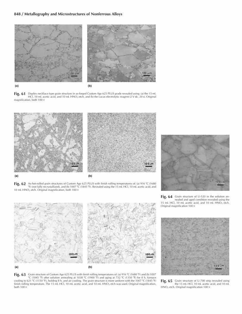
Fig. 61 Duplex necklace-type grain structure in as-forged Custom Age 625 PLUS grade revealed using: (a) the 15 mLHCl, 10 mL acetic acid, and 10 mL HNO3 etch, and (b) the Lucas electrolytic reagent (2 V dc, 20 s). Original
magnification, both 100�
Fig. 62 As-hot-rolled grain structures of Custom Age 625 PLUS with finish rolling temperatures of: (a) 916 �C (1680�F) (not fully recrystallized), and (b) 1007 �C (1845 �F). Revealed using the 15 mL HCl, 10 mL acetic acid, and
10 mL HNO3 etch. Original magnification, both 100�
Fig. 63 Grain structure of Custom Age 625 PLUS with finish rolling temperatures of: (a) 916 �C (1680 �F) and (b) 1007�C (1845 �F) after solution annealing at 1038 �C (1900 �F) and aging at 732 �C (1350 �F) for 8 h, furnace
cooling to 621 �C (1150 �F), holding 8 h, and air cooling. The grain structure is more uniform with the 1007 �C (1845 �F)finish rolling temperature. The 15 mL HCl, 10 mL acetic acid, and 10 mL HNO3 etch was used. Original magnification,both 100�
Fig. 64 Grain structure of U-520 in the solution an-nealed and aged condition revealed using the
15 mL HCl, 10 mL acetic acid, and 10 mL HNO3 etch.Original magnification 100�
Fig. 65 Grain structure of U-700 strip revealed usingthe 15 mL HCl, 10 mL acetic acid, and 10 mL
HNO3 etch. Original magnification 100�
848 / Metallography and Microstructures of Nonferrous Alloys

Fig. 66 U-710 bar. (a) Solution annealed 2 h at 1120 �C (2050 �F), aged 1.5 h at 1040 �C (1900 �F), and air cooled. Longitudinal section shows recrystallized bands (light) andbands containing residual primary c�. (b) Solution annealed 4 h at 1175 �C (2150 �F) and air cooled. Structure is dispersed primary MC carbide and M3B2 boride in a c
matrix. c� is in solution. (c) Solution annealed same as (b), aged 24 h at 845 �C (1550 �F), air cooled, aged 16 h at 760 �C (1400 �F), and air cooled. M23C6 precipitate along grain andtwin boundaries. All Kalling’s reagent. Original magnification, all 100�
Fig. 67 Coarse c� in as-forged U-720 revealed usingthe 15 mL HCl, 10 mL acetic acid, and 10 mL
HNO3 etch. Original magnification 500�
Fig. 68 Grain structure and carbides in Hastelloy B re-vealed using the 15 mL HCl, 10 mL acetic acid,
and 10 mL HNO3 etch. Original magnification 100�
Fig. 69 Grain structure of Hastelloy G30 alloy revealed using: (a) the 15 mL HCl, 10 mL acetic acid, and 10 mLHNO3 etch, and (b) the Lucas electrolytic reagent (2 V dc, 20 s). Original magnification, both 200�
Metallography and Microstructures of Heat-Resistant Alloys / 849

Fig. 70 Rene 41. (a) Solution annealed 4 h at 1065 �C (1950 �F) and air cooled. Structure consists of stringers ofcarbide in a c solid-solution matrix. Kalling’s reagent 2. Original magnification 100�. (b) Same processing
as in (a), but at higher magnification. Light, globular particles are M6C; gray particles are MC carbide; grain-boundaryenvelopes are M6C or M23C6. Kalling’s reagent 2. Original magnification 500�. (c) Solution annealed 4 h at 1065 �C(1950 �F), air cooled, aged 16 h at 760 �C (1400 �F), and air cooled. Particles of mixed carbides are present in the c solid-solution matrix, which was darkened by the formation of c� at 760 �C (1400 �F). Kalling’s reagent 2. Original magnification110� (d) Same as (c) but at a higher magnification, showing particles of M6C (white), MC (gray), and M23C6 (at grainboundaries). Grain-boundary borders are darkened by c�. Kalling’s reagent 2. Original magnification 540�
Fig. 71 Grain structure of Haynes HR-160 revealed us-ing the 15 mL HCl, 10 mL acetic acid, and 10
mL HNO3 etch. Original magnification 100�Fig. 72 Coarse c� in as-hot-isostatically pressed, powder metallurgy processed Rene 95 revealed using glyceregia. (a)
Original magnification 200�. (b) Original magnification 1000�
850 / Metallography and Microstructures of Nonferrous Alloys

Fig. 73 Grain structure and coarse, cuboidal c� and decorated prior-particle boundaries in powder processed, hotisostatically pressed, and heat treated EP741NP (1210 �C, or 2210 �F, for 8 h, furnace cool to 1160 �C, or
2120 �F, air cool, reheat to 871 �C, or 1600 �F, hold 32 h, air cool). (a) Molybdic acid reagent. 100�. (b) The Lucaselectrolytic reagent (2 V dc, 20 s). Original magnification 100�. (c) The 15 mL HCl, 10 mL acetic acid, and 10 mL HNO3etch. Original magnification 1000�. (d) Molybdic acid reagent. Original magnification 1000�
Fig. 74 Haynes 21 cobalt-base alloy, as-cast. Structureconsists of primary M7C3 particles in an �
(face-centered cubic) matrix. Electrolytic etch: HCl. Origi-nal magnification 200�
Fig. 75 Haynes 31, as-cast. Structure consists of large,primary M7C3 particles and grain-boundary
M23C6 in an � (face-centered cubic) matrix. Electrolyticetch: 2% CrO3. Original magnification 400�
Metallography and Microstructures of Heat-Resistant Alloys / 851

Fig. 77 WI-52, as-cast. The solid gray islands are com-plex chromium-tungsten carbide; eutectic car-
bides are niobium carbide. The dark dots are silicate inclu-sions in the matrix of cobalt-chromium solid solution.Electrolytic etch: 5% H3PO4. Original magnification 500�
Fig. 78 MAR-M 302, as-cast. (a) Structure consists of primary, or eutectic, M6C particles (dark gray) and MC particles(small white crystals) in the matrix of Co-Cr-W solid solution. Kalling’s reagent. Original magnification 100�.
(b) Higher magnification, with better resolution of constituents. The mottled gray islands are primary eutectic carbide; thelight crystals are MC particles; the peppery constituent within grains of the matrix is M23C6. Kalling’s reagent. Originalmagnification 500�
852 / Metallography and Microstructures of Nonferrous Alloys
Fig. 76 Haynes 151, as-cast. (a) Structure consists of dispersed islands of large primary carbide (M6C) in the � (face-centered cubic) matrix. Electrolytic etch: HCl and CrO3. Original magnification 200�. (b) Higher magnifi-
cation, which reveals details of the M6C (note the lamellar form) in the � (face-centered cubic) matrix. Electrolytic etch:HCl and CrO3. Original magnification 500�

Fig. 79 Haynes 25 (L-605). (a) Solution annealed at 1205 �C (2200 �F) and aged 3400 h at 650 �C (1200 �F). Structure is M6C and M23C6 carbides in a mixed face-centered cubic(fcc) and hexagonal close-packed matrix. Electrolytic: HCl and H2O2. Original magnification 500�. (b) Solution annealed same as (a) and aged 3400 h at 815 �C (1500
�F). Structure is precipitates of M6C and “Co2W” intermetallic in a fcc matrix. Electrolytic: HCl and H2O2. Original magnification 500�. (c) Solution annealed same as (a) and aged3400 h at 870 �C (1600 �F). Structure is the same as (b). Electrolytic: HCl and H2O2. Original magnification 500�. (d) Solution annealed same as (a) and aged 3400 h at 925 �C (1700�F). Structure consists of M6C (primary) and “Co2W” intermetallic (secondary) in a fcc matrix. Electrolytic: HCl and H2O2. Original magnification 500�. (e) Solution annealed and coldworked to 35% reduction. Hardness, 486 HV. Longitudinal section. Etched with 15 mL HCl, 10 mL acetic acid, 5 mL HNO3, and 2 drops glycerol. Original magnification 100�. Bright-field illumination. (f ) Same as (e), except dark-field illumination. (g) Same as (e), except differential interference contrast. (h) Cold worked to 35% reduction and solution annealed 2.5min at 1150 �C (2100 �F); 261 HV. Etched with 15 mL HCl, 10 mL acetic acid, 5 mL HNO3, and 2 drops glycerol. Original magnification 100�. (i) Same as (h) except solution annealed4.25 min at 1150 �C (2100 �F); 254 HV. ( j) Same has (i) except solution annealed 2.5 min at 1205 �C (2200 �F); 246 HV. Note in (h) through ( j) that grain size increases with increasingannealing temperature and time.
Metallography and Microstructures of Heat-Resistant Alloys / 853

Fig. 80 Haynes 188. (a) Cold rolled 50%, heated to 815 �C (1500 �F) for 1 h, and water quenched. The partly recrystallized structure contains M6C and M23C6 carbides in a face-centered cubic (fcc) matrix. Electrolytic: HCl and H2O2 Original magnification 1000�. (b) Cold rolled 20% and solution annealed at 1175 �C (2150 �F) for 10 min, then
water quenched. The fully annealed structure consists of M6C particles in a fcc matrix. Electrolytic: HCl and H2O2. Original magnification 500�. (c) Solution annealed at 1175 �C(2150 �F) and aged 3400 h at 650 �C (1200 �F). Structure is M6C and M23C6 particles in a fcc matrix. Electrolytic: HCl and H2O2. Original magnification 500�. (d) Solution annealedat 1175 �C (2150 �F) and aged 6244 h at 870 �C (1600 �F). Structure is M23C6, Laves phase, and probably M6C in a fcc matrix. Electrolytic: HCl and H2O2. Original magnification500�. (e) Solution annealed at 1175 �C (2150 �F), aged 6244 h at 980 �C (1800 �F). Structure consists of M6C and M23C6, and probably Laves phase, in a fcc matrix. Electrolytic: HCland H2O2. Original magnification 500�
854 / Metallography and Microstructures of Nonferrous Alloys
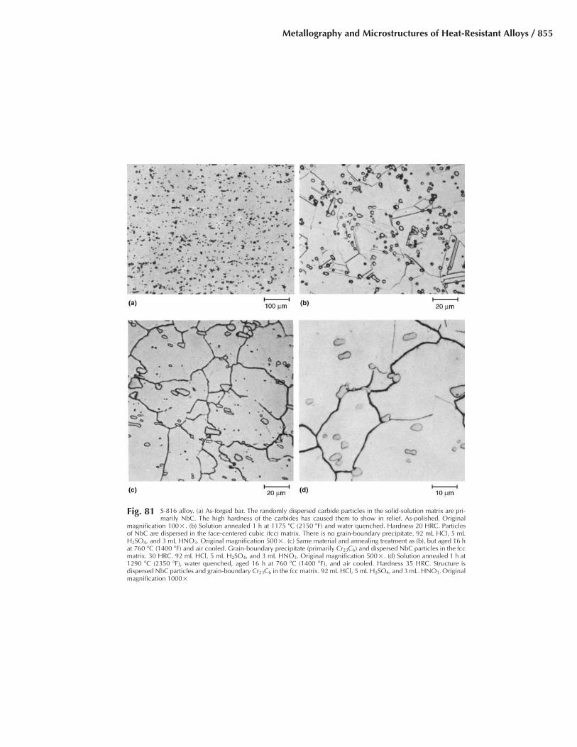
Fig. 81 S-816 alloy. (a) As-forged bar. The randomly dispersed carbide particles in the solid-solution matrix are pri-marily NbC. The high hardness of the carbides has caused them to show in relief. As-polished. Original
magnification 100�. (b) Solution annealed 1 h at 1175 �C (2150 �F) and water quenched. Hardness 20 HRC. Particlesof NbC are dispersed in the face-centered cubic (fcc) matrix. There is no grain-boundary precipitate. 92 mL HCl, 5 mLH2SO4, and 3 mL HNO3. Original magnification 500�. (c) Same material and annealing treatment as (b), but aged 16 hat 760 �C (1400 �F) and air cooled. Grain-boundary precipitate (primarily Cr23C6) and dispersed NbC particles in the fccmatrix. 30 HRC. 92 mL HCl, 5 mL H2SO4, and 3 mL HNO3. Original magnification 500�. (d) Solution annealed 1 h at1290 �C (2350 �F), water quenched, aged 16 h at 760 �C (1400 �F), and air cooled. Hardness 35 HRC. Structure isdispersed NbC particles and grain-boundary Cr23C6 in the fcc matrix. 92 mL HCl, 5 mL H2SO4, and 3 mL. HNO3. Originalmagnification 1000�
Metallography and Microstructures of Heat-Resistant Alloys / 855

Fig. 82 MP35N. (a) Solution annealed 1 h at 1065 �C (1950 �F), air cooled, and cold worked to 51% reduction. Hardness 492 HV. Longitudinal section. (b) Solution annealed sameas (a), then aged 4 h at 535 �C (1000 �F) to increase hardness to 565 HV. Longitudinal section. Both 15 mL HCl, 10 mL acetic acid, 5 mL HNO3, and 2 drops glycerol.
Original magnification, both 100�
856 / Metallography and Microstructures of Nonferrous Alloys
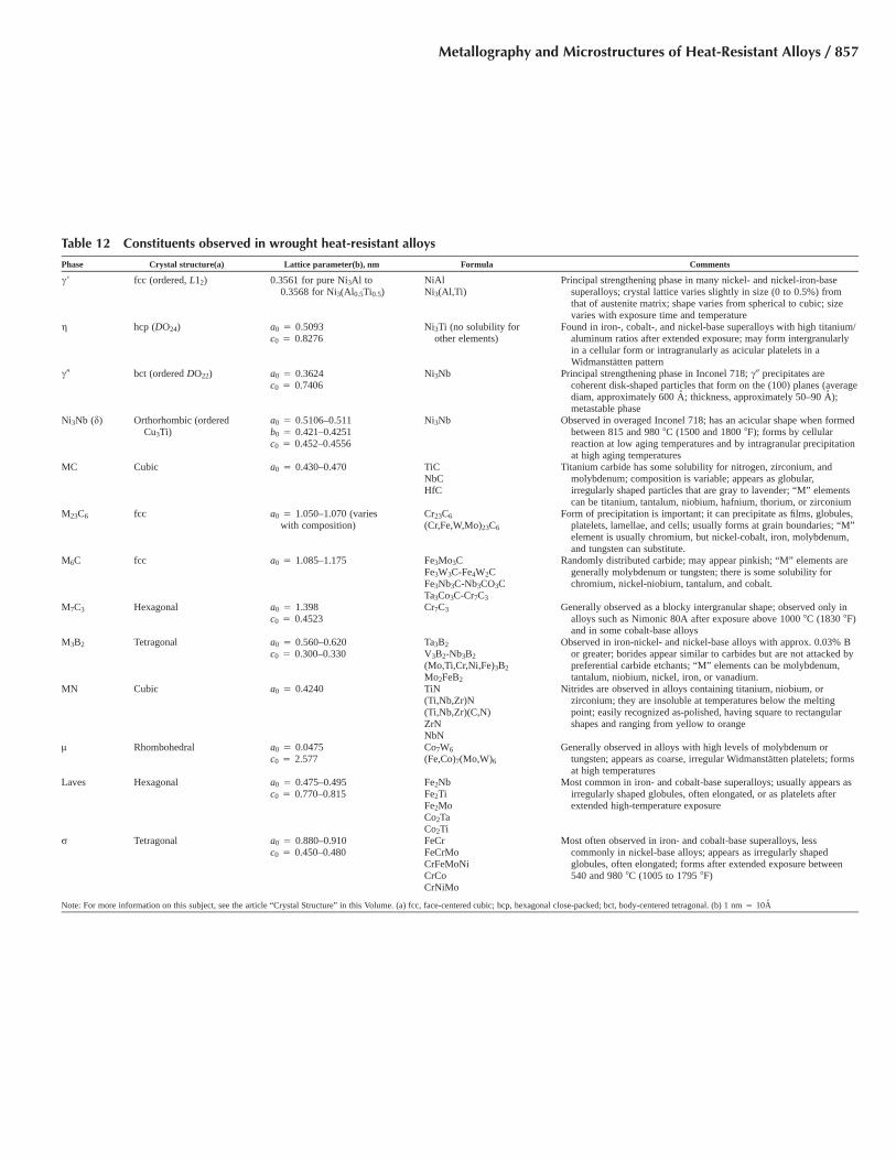
Table 12 Constituents observed in wrought heat-resistant alloys
Phase Crystal structure(a) Lattice parameter(b), nm Formula Comments
c� fcc (ordered, L12) 0.3561 for pure Ni3Al to0.3568 for Ni3(Al0.5Ti0.5)
NiAlNi3(Al,Ti)
Principal strengthening phase in many nickel- and nickel-iron-basesuperalloys; crystal lattice varies slightly in size (0 to 0.5%) fromthat of austenite matrix; shape varies from spherical to cubic; sizevaries with exposure time and temperature
g hcp (DO24) a0 � 0.5093c0 � 0.8276
Ni3Ti (no solubility forother elements)
Found in iron-, cobalt-, and nickel-base superalloys with high titanium/aluminum ratios after extended exposure; may form intergranularlyin a cellular form or intragranularly as acicular platelets in aWidmanstatten pattern
c� bct (ordered DO22) a0 � 0.3624c0 � 0.7406
Ni3Nb Principal strengthening phase in Inconel 718; c� precipitates arecoherent disk-shaped particles that form on the (100) planes (averagediam, approximately 600 A; thickness, approximately 50–90 A);metastable phase
Ni3Nb (d) Orthorhombic (orderedCu3Ti)
a0 � 0.5106–0.511b0 � 0.421–0.4251c0 � 0.452–0.4556
Ni3Nb Observed in overaged Inconel 718; has an acicular shape when formedbetween 815 and 980 �C (1500 and 1800 �F); forms by cellularreaction at low aging temperatures and by intragranular precipitationat high aging temperatures
MC Cubic a0 � 0.430–0.470 TiCNbCHfC
Titanium carbide has some solubility for nitrogen, zirconium, andmolybdenum; composition is variable; appears as globular,irregularly shaped particles that are gray to lavender; “M” elementscan be titanium, tantalum, niobium, hafnium, thorium, or zirconium
M23C6 fcc a0 � 1.050–1.070 (varieswith composition)
Cr23C6
(Cr,Fe,W,Mo)23C6
Form of precipitation is important; it can precipitate as films, globules,platelets, lamellae, and cells; usually forms at grain boundaries; “M”element is usually chromium, but nickel-cobalt, iron, molybdenum,and tungsten can substitute.
M6C fcc a0 � 1.085–1.175 Fe3Mo3CFe3W3C-Fe4W2CFe3Nb3C-Nb3CO3CTa3Co3C-Cr7C3
Randomly distributed carbide; may appear pinkish; “M” elements aregenerally molybdenum or tungsten; there is some solubility forchromium, nickel-niobium, tantalum, and cobalt.
M7C3 Hexagonal a0 � 1.398c0 � 0.4523
Cr7C3 Generally observed as a blocky intergranular shape; observed only inalloys such as Nimonic 80A after exposure above 1000 �C (1830 �F)and in some cobalt-base alloys
M3B2 Tetragonal a0 � 0.560–0.620c0 � 0.300–0.330
Ta3B2
V3B2-Nb3B2
(Mo,Ti,Cr,Ni,Fe)3B2
Mo2FeB2
Observed in iron-nickel- and nickel-base alloys with approx. 0.03% Bor greater; borides appear similar to carbides but are not attacked bypreferential carbide etchants; “M” elements can be molybdenum,tantalum, niobium, nickel, iron, or vanadium.
MN Cubic a0 � 0.4240 TiN(Ti,Nb,Zr)N(Ti,Nb,Zr)(C,N)ZrNNbN
Nitrides are observed in alloys containing titanium, niobium, orzirconium; they are insoluble at temperatures below the meltingpoint; easily recognized as-polished, having square to rectangularshapes and ranging from yellow to orange
l Rhombohedral a0 � 0.0475c0 � 2.577
Co7W6
(Fe,Co)7(Mo,W)6
Generally observed in alloys with high levels of molybdenum ortungsten; appears as coarse, irregular Widmanstatten platelets; formsat high temperatures
Laves Hexagonal a0 � 0.475–0.495c0 � 0.770–0.815
Fe2NbFe2TiFe2MoCo2TaCo2Ti
Most common in iron- and cobalt-base superalloys; usually appears asirregularly shaped globules, often elongated, or as platelets afterextended high-temperature exposure
r Tetragonal a0 � 0.880–0.910c0 � 0.450–0.480
FeCrFeCrMoCrFeMoNiCrCoCrNiMo
Most often observed in iron- and cobalt-base superalloys, lesscommonly in nickel-base alloys; appears as irregularly shapedglobules, often elongated; forms after extended exposure between540 and 980 �C (1005 to 1795 �F)
Note: For more information on this subject, see the article “Crystal Structure” in this Volume. (a) fcc, face-centered cubic; hcp, hexagonal close-packed; bct, body-centered tetragonal. (b) 1 nm � 10A
Metallography and Microstructures of Heat-Resistant Alloys / 857
REFERENCES
1. G.F. Vander Voort, Metallography: Princi-ples and Practice, McGraw-Hill, 1984; re-printed by ASM International, 1999
2. C.E. Smeltzer, Solve Steel “Freckle” Mys-tery, Iron Age, Vol 184, 10 Sept 1959, p188–189
3. G.C. Gould, Freckle Segregation in VacuumConsumable-Electrode Ingots, Trans.AIME, Vol 233, July 1965, p 1345–1351
4. J. Preston, Segregation in Vacuum-Arc-Melted Alloy Steel Ingots, Int. Trans.Vacuum Metallurgy Conf. 1967, AmericanVacuum Society, 1968, p 569–588
5. R.C. Buehl and J.K. McCauley, ProcessingImprovement in Vacuum-Arc Remelting ofIngots, Int. Trans. Vacuum Metallurgy Conf.1967, American Vacuum Society, 1968, p695–709
6. A.F. Giamei and B.H. Kear, On the Natureof Freckles in Nickel Base Superalloys, Met.Trans., Vol 1, Aug 1970, p 2185–2192
7. R. Schlatter, Electrical and Magnetic Inter-actions in Vacuum-Arc Remelting and TheirEffect on the Metallurgical Quality of Spe-cialty Steels, J. Vac. Sci. Technol., Vol 11,Nov/Dec 1974, p 1047–1054
8. E.J. Dulis and G.V. Smith, Identification andMode of Formation and Re-Solution ofSigma Phase in Austenitic Chromium-Nickel Steels, Symposium on the Nature,Occurrence and Effects of Sigma Phase,STP 110, ASTM, 1951
9. G. Petzow, Metallographic Etching, 2nd ed.,ASM International, 1999
10. C.H. Lund and H.J. Wagner, “Identificationof Microconstituents in Superalloys,”DMIC Memorandum 160, Battelle Memo-rial Institute, Columbus, OH, 15 Nov 1962
11. H.J. Beattie and F.L. Ver Snyder, Microcon-stituents in High Temperature Alloys, Trans.ASM, Vol 45, 1953, p 397–428
12. J.W. Weeton and R.A. Signorelli, Effect ofHeat Treatment upon Microstructures, Mi-croconstituents, and Hardness of WroughtCobalt Base Alloy, Trans. ASM, Vol 47,1955, p 815–852
13. H. Meisel et al., Metallographic Develop-ment of the Structure of Nickel Based Al-loys, Pract. Metallogr., Vol 17, 1980, p 261–272
14. F.R. Morral, Metallography of Cobalt-Baseand Cobalt-Containing Alloys, Pract. Me-tallogr., Vol 10, 1973, p 398–413
15. E. Kohlhaas and A. Fischer, The Metallog-raphy of Superalloys, Pract. Metallogr., Vol8, Jan 1971, p 3–25
16. W.C. Bigelow et al., Electron MicroscopicIdentification of the c� Phase of Nickel-BaseAlloys, Proc. ASTM, Vol 56, 1956, p 945–953
17. L. Bartosiewicz, Preferential ElectrolyticEtching Technique to Reveal the c� Phase inNickel Base Alloys, Pract. Metallogr., Vol10, 1973, p 450–461
18. P.K. Footner and B.P. Richards, A Rapid
Method for Measurement of c� Size Distri-bution in Nickel-Base Superalloys, Pract.Metallogr., Vol 17, 1980, p 489–496
19. C.P. Sullivan, The Metallographic Identifi-cation of Borides in Udimet 700, Trans.ASM, Vol 58, 1965, p 702–705
20. H.S. Avery, V.O. Homerberg, and E. Cook,Metallographic Identification of Ferro Mag-netic Phases, Met. Alloys, Vol 10, 1939, p353–355
21. H.S. Avery, “Cast Heat-Resistant Alloys forHigh-Temperature Weldments,” Bulletin143, Welding Research Council, Aug 1969
22. A New Way to Reveal Magnetic Domainsat High Magnifications, Met. Prog., Vol 100,Dec 1971, p 82
23. W.C. Elmore, Ferromagnetic Colloid forStudying Magnetic Structures, Phys. Rev.,Vol 54, 1938, p 309–310
24. Gray, “Revealing Ferromagnetic Micro-structures with Ferrofluid,” Report RNL-TM-3681, Oak Ridge National Laboratory,March 1972
25. G.N. Maniar and A. Szirmae, Ed., Manualon Electron Metallography Techniques, STP547, ASTM, 1973
26. I.S. Brammar and M.A.P. Dewey, SpecimenPreparation for Electron Metallography,Blackwell Scientific, 1966
27. G. Thomas, Transmission Electron Micros-copy of Metals, John Wiley & Sons, 1964
28. J.R. Mihalisin, The Selective Identificationof Constituents in Nimonic 80 by Extrac-tion-Replica Technique, Trans. AIME, Vol212, June 1958, p 349–350
29. E. Kohlhaas and A. Fischer, The Use of theCarbon-Extraction Technique in Investiga-tions of Superalloys, Pract. Metallogr., Vol6, 1969, p 291–298
30. R.J. Seher and G.N. Maniar, AnalyticalPreshadowed Extraction Replica Technique,Metallography, Vol 5, 1972, p 409–414
31. W.L. Mankins, Chromic Acid as an Electro-lytic Etchant and Electrolyte for the Extrac-tion of c� in Nickel-Base Superalloys, Met-allography, Vol 9, 1976, p 227–232
32. A.J. Portner and B. Ralph, A Technique forthe Replication of c� in Nickel-Base Super-alloys, Pract. Metallogr., Vol 16, 1979, p592–601
33. K.C. Thompson-Russell and J.W. Edington,Electron Microscope Specimen PreparationTechniques in Materials Science, Part 5,Practical Electron Microscopy in MaterialsScience, Philips Electronic Instruments,1977
34. L. Bartosiewicz, Improved Techniques ofThin Foil Preparation of Ni Base Alloys forElectron Microscopy, Pract. Metallogr., Vol9, 1972, p 525–534
35. C. Hays and D.A. Nail, Transmission Elec-tron Microscopy of Incoloy Alloy 901, Met-allography, Vol 7, 1974, p 59–68
36. R.E. Schafrik and M. Henry, TransmissionElectron Microscopy Foil Preparation andResults for Incoloy 901, Metallography, Vol13, 1980, p 157–165
37. T.P. Hoar and K.W.J. Bowen, The Electro-lytic Separation and Some Properties ofAustenite and Sigma in 18-8-3-1 Chro-mium-Nickel Molybdenum-Titanium Steel,Trans. ASM, Vol 45, 1953, p 443–474
38. J.F. Brown et al., The Extraction of MinorPhases from Austenitic Steel, Metallurgia,Vol 56, Nov 1957, p 215–223
39. K.W. Andrews and H. Hughes, The Isola-tion, Separation, and Identification of Mi-croconstituents in Steels, in STP 393,ASTM, 1966, p 3–21
40. O.H. Kriege and C.P. Sullivan, The Sepa-ration of Gamma Prime from Udimet 700,Trans. ASM, Vol 61, 1968, p 278–282
41. O.H. Kriege and J.M. Baris, The ChemicalPartitioning of Elements in Gamma PrimeSeparated from Precipitation-Hardened,High-Temperature Nickel-Base Alloys,Trans. ASM, Vol 62, 1969, p 195–200
42. M.J. Donachie and O.H. Kriege, Phase Ex-traction and Analysis in Superalloys Sum-mary of Investigations by ASTM Commit-tee E-4 Task Group 1, J. Mater., Vol 7, Sept1972, p 269–278
43. O.H. Kriege, Phase Separation as a Tech-nique for the Characterization of Superal-loys, in STP 557, ASTM, 1974, p 220–234
44. E. Kny, On the Methodology of Phase Ex-traction in Ni-Base Superalloys, Pract. Me-tallogr., Vol 13, Nov 1976, p 549–564
45. “Practice for Electrolytic Extraction ofPhases from Ni and Ni-Fe Base SuperalloysUsing a Hydrochloric-Methanol Electro-lyte,” E 963, Annual Book of ASTM Stan-dards, ASTM, 1984
46. C. Razim, Metallography of Heat Resistantand High Temperature Alloys, Pract. Me-tallogr., Vol 5, May 1968, p 225–241; June1968, p 299–309
47. G.P. Sabol and R. Stickler, Microstructureof Nickel-Base Superalloys, Phys. StatusSolidi, Vol 35 (No. 1), 1968, p 11–52
48. P.S. Kotval, The Microstructure of Super-alloys, Metallography, Vol 1, 1969, p 251–285
49. F.R. Morral et al., Microstructure of Cobalt-Base High-Temperature Alloys, ASM Met.Eng. Q., Vol 9, May 1969, p 1–16
50. J.F. Radavich and W.H. Couts, Metallogra-phy of the Superalloys, Rev. High-Temp.Mater., Vol 1, Aug 1971, p 55–96
51. C.P. Sullivan and M.J. Donachie, Some Ef-fects of Microstructure on the MechanicalProperties of Nickel-Base Superalloys, ASMMet. Eng. Q., Vol 7, Feb 1967, p 36–45
52. R.F. Decker, Strengthening Mechanisms inNickel-Base Superalloys, Symposium:Steel-Strengthening Mechanisms, 5–6 May1969 (Zurich), 1970, p 147–170
53. C.T. Sims and W.C. Hagel, Ed., The Super-alloys, John Wiley & Sons, 1972
54. C.P. Sullivan et al., Relationship of Proper-ties to Microstructure in Cobalt-Base Su-peralloys, ASM Met. Eng. Q., Vol 9, May1969, p 16–29
55. C.P. Sullivan and M.J. Donachie, Micro-
858 / Metallography and Microstructures of Nonferrous Alloys

structures and Mechanical Properties ofIron-Base (-Containing) Superalloys, ASMMet. Eng. Q., Vol 11, Nov 1971, p 1–11
56. D.R. Muzyka, Controlling Microstructureand Properties of Superalloys via Use ofPrecipitated Phases, ASM Met. Eng. Q., Vol11, Nov 1971, p 12–20
57. D.R. Muzyka and G.N. Maniar, Microstruc-ture Approach to Property Optimization inWrought Superalloys, in STP 557, ASTM,1974, p 198–219
58. W.T. Loomis et al., The Influence of Molyb-denum on the c� Phase in ExperimentalNickel-Base Superalloys, Met. Trans., Vol 3,April 1972, p 989–1000
59. J.F. Barker, A Superalloy for Medium Tem-peratures, Met. Prog., Vol 81, May 1962, p72–76
60. I. Kirman and D.K. Warrington, Identifica-tion of the Strengthening Phase in Fe-Ni-Cr-Nb Alloys, J. Iron Steel Inst., Vol 205, Dec1967, p 1264–1265
61. P.S. Kotval, Identification of the Strength-ening Phase in “Inconel” Alloy 718, Trans.AIME, Vol 242, Aug 1968, p 1764–1765
62. D.F. Paulonis et al., Precipitation in Nickel-Base Alloy 718, Trans. ASM, Vol 62, 1969,p 611–622
63. W.J. Boesch and H.B. Canada, PrecipitationReactions and Stability of Ni3Cb in InconelAlloy 718, J. Met., Vol 21, Oct 1969, p 34–38
64. I. Kirman and D.H. Warrington, The Pre-cipitation of Ni3Nb Phases in a Ni-Fe-Cr-Nb
Alloy, Met. Trans., Vol 1, Oct 1970, p 2667–2675
65. R. Cozar and A. Pineau, Morphology of c�and c� Precipitates and Thermal Stability ofInconel 718 Type Alloys, Met. Trans., Vol4, Jan 1973, p 47–59
66. J.R. Mihalisin and R.T. Decker, PhaseTransformations in Nickel-Rich Nickel-Ti-tanium-Aluminum Alloys, Trans. AIME,Vol 218, June 1960, p 507–515
67. B.R. Clark and F.B. Pickering, PrecipitationEffects in Austenitic Stainless Steels Con-taining Titanium and Aluminum Additions,J. Iron Steel Inst., Vol 205, Jan 1967, p 70–84
68. L.K. Singhal and J.W. Martin, PrecipitationProcesses in an Austenitic Stainless SteelContaining Titanium, J. Iron Steel Inst., Vol205, Sept 1967, p 947–952
69. E.L. Raymond, Effect of Grain BoundaryDenudation of Gamma Prime on Notch-Rupture Ductility of Inconel Nickel-Chro-mium Alloys X750 and 718, Trans. AIME,Vol 239, Sept 1967, p 1415–1422
70. H.J. Beattie, The Crystal Structure of aM3B2 Type Double Boride, Acta Crystal-logr., Vol 11, 1958, p 607–609
71. L.R. Woodyatt et al., Prediction of Sigma-Type Phase Occurrence from Compositionsin Austenitic Superalloys, Trans. AIME, Vol236, 1966, p 519–527
72. E.O. Hall and S.H. Algie, The Sigma Phase,Met. Rev., Vol 11, 1996, p 61–88
73. J.R. Mihalisin et al., Sigma—Its Occur-rence, Effect, and Control in Nickel-BaseSuperalloys, Trans. AIME, Vol 242, Dec1968, p 2399–2414
74. R.G. Barrows and J.B. Newkirk, A ModifiedSystem for Predicting a Formation, Met.Trans., Vol 3, Nov 1972, p 2889–2893
75. E.S. Machlin and J. Shao, SIGMA-SAFE:A Phase Diagram Approach to the SigmaPhase Problem in Ni-Base Superalloys, Met.Trans. A, Vol 9, April 1978, p 561–568
76. A. Raman, The l Phases, Z. Metallkd., Vol57, April 1966, p 301–305
77. H.J. Beattie and F.L. Ver Snyder, A NewComplex Phase in a High-Temperature(Iron-Nickel-Chromium-Molybdenum) Al-loy, Nature, Vol 178 (No. 4526), 1956, p208–209
78. H.J. Beattie and W.C. Hagel, IntermetallicCompounds in Titanium-Hardened Alloys,Trans. AIME, Vol 209, July 1957, p 911–917
79. K.W. Andrews and H. Hughes, Discussionof Aging Reactions in Certain Superalloys,Trans. ASM, Vol 49, 1957, p 999
80. G.F. Slattery, Microstructural Aspects ofAluminized Coatings on Nickel-Base Al-loys, Met. Technol., Vol 10, Feb 1983, p 41–51
81. G.W. Goward et al., Formation and Degra-dation Mechanisms of Aluminide Coatingson Nickel-Base Superalloys, Trans. ASM,Vol 60, 1967, p 228–241
Metallography and Microstructures of Heat-Resistant Alloys / 859