Metallographic preparation of thermal spray coatings ... · Metallographic preparation of thermal...
6
Application Notes Metallographic preparation of thermal spray coatings Thermal spraying was invented in the early 1900s using zinc for „metallizing” substrates for corrosion protection. The development of the plasma spray gun in the late 50s and 60s made it commercially viable to use high temperature materials such as ceramics and refractory metals for coating materials. In addition to flame and plasma spraying, today thermal spray methods include high velocity and detona- tion spraying using a multitude of different spray materials for the most diverse and demanding applications. Thermal spray coatings are applied to a substrate to give a specific surface quali- ty, which it originally does not have. Thus the bulk strength of a part is given by the substrate, and the coating adds superior surface qualities such as corrosion, wear or heat resistance. Therefore thermal spray coatings are wide- ly used in the aerospace and power gene- ration industry for new and refurbished sections and parts for jet engines and gas turbines, compressors and pumps. The properties of some coatings can only be fabricated by thermal spraying, using mainly metals, ceramics, carbides and composites as well as mixtures of various materials. Metallography of thermal spray coatings can have several purposes: - To define, monitor and control spraying conditions for quality control - For failure analysis - For developing new products. The procedure normally involves coating a test coupon to define and optimize the pro- cess for the part to be sprayed. Sections of this test coupon are then metallographi- cally prepared and examined to assess coating thickness, size and distribution of porosity, oxides and cracks, adhesion to base material, interface contamination and presence of unmelted particles. Cutting: Cracks in the coating due to clamping the sample and using coarse cut-off wheels; Delamination from substrate Mounting: Insufficient penetration of mounting resin Difficulties during metallographic preparation Solution: - Precision cutting - Vacuum impregnation with epoxy resin - Standardized, reproducible preparation methods for thermal spray coatings Electric arc metal spray coating, showing grey oxides and round, unmelted particles Grinding and polishing: Because of smear- ing of soft materials and pull-outs in brittle materials, it is difficult to establish and evaluate true porosity Fig. 2: Same coating as Fig.1, 200x polished correctly Fig.1: Ceramic spray coating, 200x insufficiently polished Crack between a plasma spray coating 500x and the substrate. The crack originates from cutting
Transcript of Metallographic preparation of thermal spray coatings ... · Metallographic preparation of thermal...
Application Notes
Metallographic preparation of thermal spray coatingsThermal spraying was invented in the early 1900s using zinc for „metallizing” substrates for corrosion protection. The development of the plasma spray gun in the late 50s and 60s made it commercially viable to use high temperature materials such as ceramics and refractory metals for coating materials. In addition to flame and plasma spraying, today thermal spray methods include high velocity and detona-tion spraying using a multitude of different spray materials for the most diverse and demanding applications.
Thermal spray coatings are applied to a substrate to give a specific surface quali-ty, which it originally does not have. Thus the bulk strength of a part is given by the substrate, and the coating adds superior surface qualities such as corrosion, wear or heat resistance. Therefore thermal spray coatings are wide-ly used in the aerospace and power gene-ration industry for new and refurbished sections and parts for jet engines and gas turbines, compressors and pumps. The properties of some coatings can only be fabricated by thermal spraying, using mainly metals, ceramics, carbides and composites as well as mixtures of various materials.
Metallography of thermal spray coatings can have several purposes: - To define, monitor and control spraying conditions for quality control- For failure analysis - For developing new products.
The procedure normally involves coating a test coupon to define and optimize the pro-cess for the part to be sprayed. Sections of this test coupon are then metallographi-cally prepared and examined to assess coating thickness, size and distribution of porosity, oxides and cracks, adhesion to base material, interface contamination and presence of unmelted particles.
Cutting: Cracks in the coating due to clamping the sample and using coarse cut-off wheels;Delamination from substrate
Mounting: Insufficient penetration of mounting resin
Difficulties during metallographic preparation Solution:- Precision cutting- Vacuum impregnation with epoxy resin- Standardized, reproducible preparation methods for thermal spray coatings
Electric arc metal spray coating, showing grey oxides and round, unmelted particles
Grinding and polishing: Because of smear-ing of soft materials and pull-outs in brittle materials, it is difficult to establish and evaluate true porosity
Fig. 2: Same coating as Fig.1, 200xpolished correctly
Abb. 2: Selbe Beschichtung wie Abb. 1, 200xkorrekt poliert
Fig. 2 : le même revêtement 200xque fig. 1, poli correctement
Fig. 2: Mismo recubrimiento que en 200xla Fig. 1, pulido correctamente
图 2:与图 1 相同的涂层,正确抛光 200x
Fig.1: Ceramic spray coating, 200xinsufficiently polished
Abb. 1: Keramische Spritzschicht, 200xunzureichend poliert
Fig. 1 : revêtement par projection de 200xcéramique insuffisamment poli
Fig. 1: Recubrimiento cerámico pulverizado, 200xcon pulido insuficiente
图 1:陶瓷喷涂层,抛光不足 200x
Crack between a plasma spray coating 500xand the substrate. The crack originates from cutting
Riss zwischen Plasmaspritzschicht und 500xTrägermaterial. Der Riss wurde beim Trennen verursacht
Fissure entre un revêtement plasma et le 500xsubstrat. La fissure vient du tronçonnage.
Fractura entre un recubrimiento de 500xpulverización por plasma y el substrato.La fractura se origina en el corte
等离子涂层与基板之间的裂缝。裂缝源于切割 500x.
Spray methods and applications of thermal spray coatings
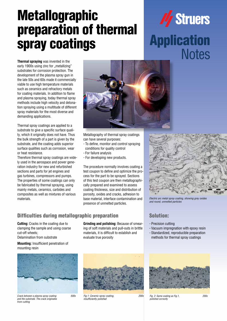
In the spraying process the coating mate-rial, wire or powder, melts in a high tem-perature heat source in a spray gun and is accelerated by the flame or plasma jet and projected towards the substrate. A stream of molten and semi-molten particles im-pinges onto the substrate and forms a coating. When the particles hit the work- piece they mechanically lock onto the sur-face, deform and cool rapidly. The bonding of single particles is through mechanical interlocking, or in some cases metallurgical bonding or diffusion. High velocity of the particles leads to better bonding and higher density of the coating. For good adhesion to the substrate it is essential that the surface is roughened by sandblasting and thoroughly degreased and cleaned before spraying. The various spraying techniques display different temperatures at the heat source and different particle velocities, which, together with the economical aspect, need to be taken into consideration for specific applications. In the following the main spraying techniques are briefly described and some of the most well-known applica-tions of the resulting coatings mentioned:
Flame spraying is the oldest method of ap-plying thermal spray coatings. The coating material is either wire or powder, which is fed into an oxygen-fuel gas flame. The molten and atomized particles are ejected in a directed stream through the spraying gun nozzle. Due to the relatively low particle velocity the oxygen exposure is increased
the workpiece with extremely high kinetic energy. These coatings have an excel-lent density, integrity and adhesion to the substrate. Due to the process conditions this method is limited to the application of carbide coatings, mainly in the aerospace and aviation industry for wear-resistant coatings.
In High Velocity Oxy-Fuel Combustion spraying (HVOF) fuel gas and oxygen are fed into a chamber in which combustion produces a supersonic flame, which is forced down a nozzle increasing its veloc-ity. Powder of coating material is fed into this stream and the extreme velocity of the particles when hitting the substrate creates
Fig. 3: Flame sprayed coating; Ni5Al
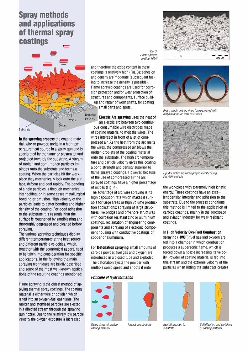
Brass synchronising rings flame-sprayed with molybdenum for wear resistance
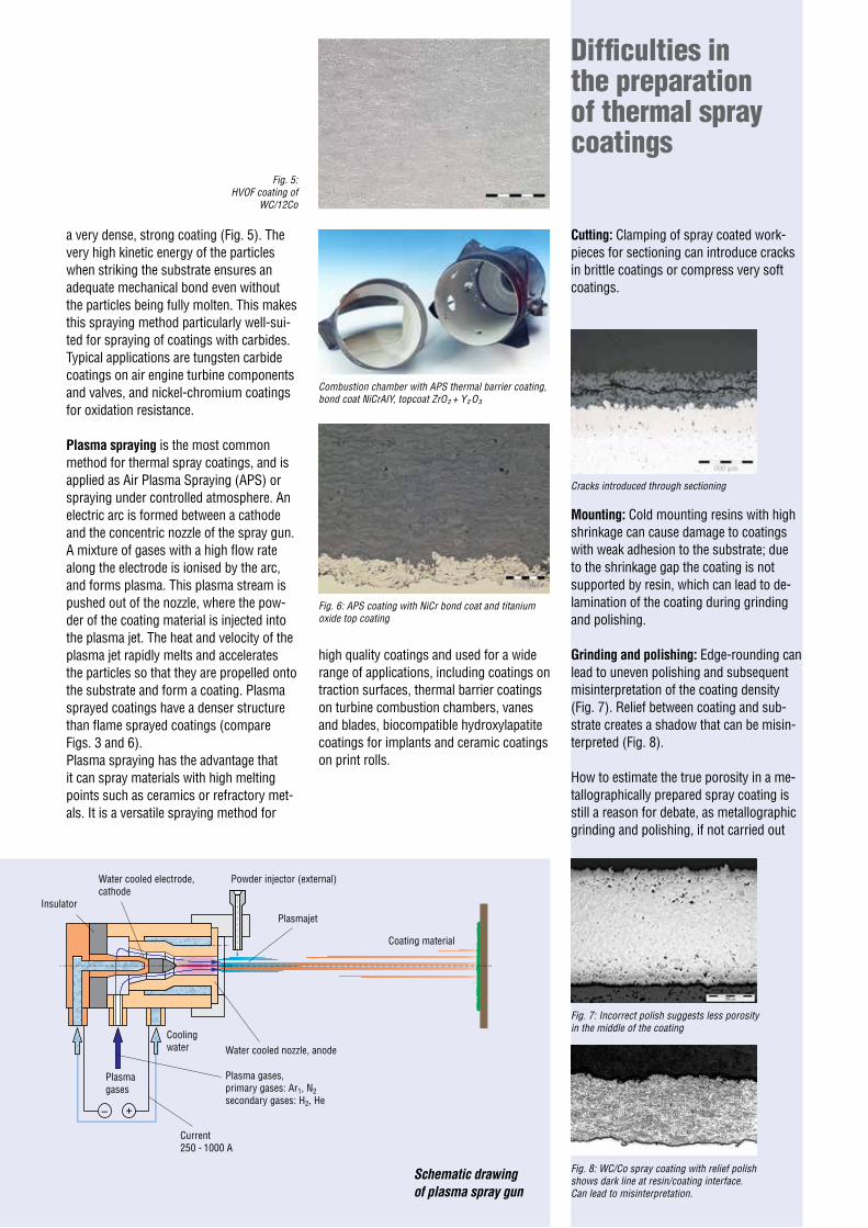
Fig. 4: Electric arc wire-sprayed metal coating FeCrSiNi and Mn
Flying drops of molten coating material
Impact on substrate Heat dissipation to substrate
Solidification and shrinking of coating material
and therefore the oxide content in these coatings is relatively high (Fig. 3); adhesion and density are moderate (subsequent fus-ing to increase the density is possible). Flame sprayed coatings are used for corro-sion protection and/or wear protection of structures and components, surface build-
up and repair of worn shafts, for coating small parts and spots.
Electric Arc spraying uses the heat of an electric arc between two continu-
ous consumable wire electrodes made of coating material to melt the wires. The wires intersect in front of a jet of com-pressed air. As the heat from the arc melts the wires, the compressed air blows the molten droplets of the coating material onto the substrate. The high arc tempera-ture and particle velocity gives this coating a bond strength and density superior to flame sprayed coatings. However, because of the use of compressed air the arc sprayed coatings have a higher percentage of oxides (Fig. 4). The advantage of arc wire spraying is its high deposition rate which makes it suit-able for large areas or high volume produc-tion applications: spraying of large struc-tures like bridges and off-shore structures with corrosion resistant zinc or aluminium coatings, reclamation of engineering com-ponents and spraying of electronic compo-nent housing with conductive coatings of copper or aluminium.
For Detonation spraying small amounts of carbide powder, fuel gas and oxygen are introduced in a closed tube and exploded. The detonation ejects the powder with multiple sonic speed and shoots it onto
Unmelted particles
Oxides
Voids
Substrate
Principle of layer formation
+–
Difficulties in the preparation of thermal spray coatings
Fig. 5: HVOF coating of
WC/12Co
a very dense, strong coating (Fig. 5). The very high kinetic energy of the particles when striking the substrate ensures an adequate mechanical bond even without the particles being fully molten. This makes this spraying method particularly well-sui-ted for spraying of coatings with carbides. Typical applications are tungsten carbide coatings on air engine turbine components and valves, and nickel-chromium coatings for oxidation resistance.
Plasma spraying is the most common method for thermal spray coatings, and is applied as Air Plasma Spraying (APS) or spraying under controlled atmosphere. An electric arc is formed between a cathode and the concentric nozzle of the spray gun. A mixture of gases with a high flow rate along the electrode is ionised by the arc, and forms plasma. This plasma stream is pushed out of the nozzle, where the pow-der of the coating material is injected into the plasma jet. The heat and velocity of the plasma jet rapidly melts and accelerates the particles so that they are propelled onto the substrate and form a coating. Plasma sprayed coatings have a denser structure than flame sprayed coatings (compare Figs. 3 and 6).Plasma spraying has the advantage that it can spray materials with high melting points such as ceramics or refractory met-als. It is a versatile spraying method for
Cutting: Clamping of spray coated work- pieces for sectioning can introduce cracks in brittle coatings or compress very soft coatings.
Combustion chamber with APS thermal barrier coating, bond coat NiCrAlY, topcoat ZrO² + Y² O³
high quality coatings and used for a wide range of applications, including coatings on traction surfaces, thermal barrier coatings on turbine combustion chambers, vanes and blades, biocompatible hydroxylapatite coatings for implants and ceramic coatings on print rolls.
Insulator
Water cooled electrode, cathode
Powder injector (external)
Plasmajet
Coating material
Water cooled nozzle, anode
Plasma gases, primary gases: Ar1, N2 secondary gases: H2, He
Current 250 - 1000 A
Cooling water
Plasma gases
Fig. 6: APS coating with NiCr bond coat and titanium oxide top coating
Fig. 7: Incorrect polish suggests less porosity in the middle of the coating
Cracks introduced through sectioning
Fig. 8: WC/Co spray coating with relief polish shows dark line at resin/coating interface. Can lead to misinterpretation.
Mounting: Cold mounting resins with high shrinkage can cause damage to coatings with weak adhesion to the substrate; due to the shrinkage gap the coating is not supported by resin, which can lead to de-lamination of the coating during grinding and polishing.
Grinding and polishing: Edge-rounding can lead to uneven polishing and subsequent misinterpretation of the coating density (Fig. 7). Relief between coating and sub-strate creates a shadow that can be misin-terpreted (Fig. 8).
How to estimate the true porosity in a me-tallographically prepared spray coating is still a reason for debate, as metallographic grinding and polishing, if not carried out
Schematic drawing of plasma spray gun
correctly, can introduce artefacts which are not part of the coating structure. For exam-ple, in metal or metal/ceramic coatings, the softer metal is smeared into pores during grinding and if not polished properly can cover up the true porosity (see Figs. a-c). In comparison, ceramic coatings are brit-tle and particles break out of the surface during grinding. If not polished thoroughly, these break-outs leave an incorrect impres-sion of a high porosity (see Figs. d-f).
Recommendations for the preparation of thermal spray coatingsAs there are many different spraying materials with sometimes unusual com-binations, it is important to know the correct spraying and substrate material. It facilitates to estimate how the materials will behave under mechanical abrasion. As dif-ferent spraying processes result in different coating densities and structures it also helps to know the spraying method used on a particular sample in order to estimate the expected porosity and oxide content.
Cutting: Selection of the cut-off wheel is based on the substrate material, which is usually metallic. A wheel with a looser bond (soft) is preferable to a denser bond (hard) as brittle particles of the coating are dragged out by a hard cut-off wheel. This is particularly important when cutting parts with ceramic coatings. Even if the coat-ing is ceramic, it constitutes only a small percentage of the total cross section-al area and does not need to be cut with a diamond cut-off wheel. Usually sectioning is possible with a soft aluminium oxide wheel. If the ceramic coating is very thick and dense a resin-bonded diamond cut-off wheel can be used as an alternative.
A thin piece of styrofoam between clamps and sample can help to protect brittle and very soft coatings from being damaged.
d) Ceramic spray coating after fine grinding
a) Metal spray coating after fine grinding
b) Same coating as in a) polished with 3 µm
c) Same coating as in b) after final polish
e) Same coating as in d) polished with 3 µm
f) Same coating as in e) after final polish
When cutting pieces other than test cou-pons, for instance samples for failure analysis, it is important to ensure that the workpiece is clamped into the cut-off ma-chine in such a way that the cut-off wheel is cutting into the coating towards the substrate, and not from the substrate into the coating. As the bond of the coating is mainly mechanical, it can delaminate from the substrate due to the drag of the cut-off wheel.
Particularly fragile or thin coatings can first be vacuum impregnated with cold mounting epoxy resin, and then the micro sections are cut and remounted for grind-ing and polishing. This ensures maximum support to the coating during sectioning.
The appearance of cracks in a coating after final polishing may or may not be the result of cutting. It is recommended to regrind and polish the sample. If the crack is from cutting it will usually disappear, if it is inherent in the coating it will reappear, or cracks will surface in other areas of the coating.
Mounting: Cold mounting with epoxy resin (ProntoFix , EpoFix, CaldoFix-2) is recom-mended as spray coatings are very easily damaged during hot compression mount-ing (Figs. 9 and 10). In general, vacuum impregnation is rec-
ommended for all coatings. The depth of impregnation var-ies with the degree of open porosity and interconnections be-tween the pores. Very
porous coatings can be easier impregnated than denser ones, and coatings with less than 10% porosity can not be impreg-nated successfully. As it can be difficult to distinguish voids filled with transparent or translucent mounting resins from the structural elements of the coating, it helps to mix a fluorescent dye (Epodye) into the cold mounting resin. Viewed with a long pass blue filter and a short pass orange filter in the microscope, the fluorescent dye
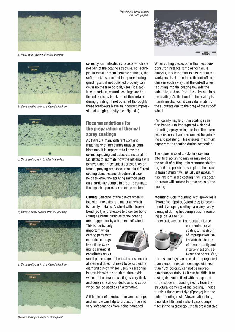
Nickel flame spray coating with 15% graphite
Step PG FG
Step DP 1 DP 2 **
Grinding
Polishing
will colour those voids yellow which have been filled with resin by the impregnation (Fig.11 and 12).Unfortunately this method is not always applicable for ceramic coatings, because ceramics are translucent and the whole coating appears fluorescent.
Grinding and polishing: As a general rule plane grinding should start with the finest possible silicon carbide foil/paper to avoid creating artificial porosity by fracturing brit-tle particles. Exceptions can be very dense or thick ceramic coatings, which are plane ground more efficiently with diamond (with e.g. MD-Piano 220). For high sample volumes or large parts, which need to be
Fig.12: Same coating as in Fig.11 in fluorescent light
Fig.11: WC/Co plasma spray coating in bright field
examined as a whole, plane grinding with a stone may be preferred as it is faster. Whichever method is use, one must always be aware that the first preparation step should aim to re-move any cracks that arise from cutting without introducing new damage from coarse grinding.
To retain flatness and assure a good mate-rial removal rate, fine grinding is preferably done with diamond on a composite fine grinding disc. For ceramic coatings the fine grinding disc MD-Allegro is recommended, and for metal coatings MD-Largo. A tho-rough polishing on a silk cloth (MD-Dur or MD-Dac) will retain the flatness of the sam-ple and guarantee the removal of smeared metal.
Metal coatings can be fine polished either with 1 µm diamond or a colloidal silica (OP-U NonDry) on a soft cloth. It is not recommended to use the colloidal silica suspension OP-S NonDry for polishing metal spray coatings as it creates too much relief. However, OP-S NonDry is suitable for the final polishing of ceramic coatings as it gives a good contrast to the structure.
In the trial stage for establishing prepara-tion methods both silicon carbide and diamond grinding can be tried to find out which is the more suitable plane grinding method. The same applies to the final pol-ishing step, for which 1µm diamond might in some cases be preferable to colloidal silica.
In general it is recommended that, if pos-sible, a standard procedure is always used for all coatings. With automatic preparation equipment it is possible to control prepara-tion parameters, which guarantees consist-ent results and excellent reproducibility. By keeping the preparation conditions con-stant, it can then be assumed that sudden differences in the microstructure in most cases reflect differences in the spraying process and not in the preparation process.
The preparation method in the table above has successfully been used for the most common coatings. The data are for 6 mounted samples, 30 mm diameter, clamped into a holder. DiaPro diamond suspension can be replaced by DP-Sus-pension 9 µm, 3 µm and 1 µm respectively, applied with blue lubricant.
Etching: In general, etchants that are rec-ommended for a specific material can also be used for spray coatings of this material.It can be expected that the more similar the substrate and coating materials are, the more even the etching attack will be.
Valid for 6 mounted samples, 30 mm diam. clamped in a holder.
Remarks:
*Alternatively DiaPro diamond suspension can be replaced by DP-Suspension, P, 9 µm, 3 µm and 1 µm respectively, applied with blue lubricant.
**Alternatively, this diamond polishing step can be replaced by a polishing step with colloidal silica (OP-U NonDry for metal, OP-S NonDry for ceramic coatings) for 30-60 sec.
Standard preparation method for thermal spray coatings
Type
Size
Type
Size
Abrasive
Abrasive
Surface
Surface
Suspension/ Lubricant
Suspension/ Lubricant
rpm
rpm
Force [N]/ specimen
Force [N]/ specimen
Time (min)
Time (min)
Water
DiaPro Dac 3*
300
150
30
30
Until plane
5
Diamond
9 μm
Diamond
1 μm
MD-Largo
MD-Nap
DiaPro Allegro/Largo 9*
DiaPro Nap B 1*
150
150
30
20
5
1
SiC
#220
Diamond
3 μm
Foil/Paper
MD-Dac
Fig.9: Damage to ceramic spray coating 200xdue to hot compression mounting
Abb. 9: Beschädigung einer keramischen 200xSpritzschicht durch Heißeinbetten
Fig. 9 : endommagement d'un revêtement 200xpar projection de céramique dû àun enrobage à chaud avec compression
Fig. 9: Daño en recubrimiento con spray cerámico 200xdebido a embutición en caliente
图 9:由于热压缩镶样对陶瓷喷涂层造成的损坏 200x
Fig.10: Same coating as in Fig. 9, cold mounted 200x
Abb. 10: Dieselbe Beschichtung 200xwie in Abb. 9, in Kalteinbettung
Fig. 10 : même revêtement que fig. 9, 200xenrobé à froid
Fig. 10: Mismo recubrimiento que en la Fig. 9; 200xembutición en frío
图 10:与图 9 相同的涂层,冷镶嵌 200x
Struers ApSPederstrupvej 84 DK-2750 Ballerup, Denmark Phone +45 44 600 800Fax +45 44 600 [email protected] www.struers.com
AUSTRALIAN & NEW ZEALANDStruers Australia27 Mayneview StreetMilton QLD 4064AustraliaPhone +61 7 3512 9600Fax +61 7 3369 [email protected]
BELGIUM (Wallonie)Struers S.A.S.370, rue du Marché RollayF- 94507 Champigny sur Marne CedexTéléphone +33 1 5509 1430Télécopie +33 1 5509 [email protected]
BELGIUM (Flanders)Struers GmbH NederlandZomerdijk 34 A3143 CT MaassluisTelefoon +31 (10) 599 7209Fax +31 (10) [email protected]
CANADAStruers Ltd.7275 West Credit AvenueMississauga, Ontario L5N 5M9Phone +1 905-814-8855Fax +1 [email protected]
CHINAStruers Ltd.No. 1696 Zhang Heng RoadZhang Jiang Hi-Tech ParkShanghai 201203, P.R. ChinaPhone +86 (21) 6035 3900Fax +86 (21) 6035 [email protected]
CZECH REPUBLIC & SLOVAKIAStruers GmbH Organizační složkavědeckotechnický parkPřílepská 1920,CZ-252 63 Roztoky u PrahyPhone +420 233 312 625Fax +420 233 312 [email protected]@struers.de
GERMANYStruers GmbHCarl-Friedrich-Benz-Straße 5D- 47877 WillichTelefon +49 (0) 2154 486-0Fax +49 (0) 2154 [email protected]
FRANCEStruers S.A.S.370, rue du Marché RollayF-94507 Champigny sur Marne CedexTéléphone +33 1 5509 1430Télécopie +33 1 5509 [email protected]
HUNGARY Struers GmbH Magyarországi Fióktelep Tatai ut 53 2821 Gyermely Phone +36 (34) 880546 Fax +36 (34) 880547 [email protected]
IRELANDStruers Ltd.Unit 11 Evolution@ AMPWhittle Way, CatcliffeRotherham S60 5BLTel. +44 0845 604 6664Fax +44 0845 604 [email protected]
ITALYStruers ItaliaVia Monte Grappa 80/420020 Arese (MI)Tel. +39-02/38236281Fax +39-02/[email protected]
JAPANMarumoto Struers K.K.Takanawa Muse Bldg. 1F3-14-13 Higashi-Gotanda,ShinagawaTokyo 141-0022 JapanPhone +81 3 5488 6207 Fax +81 3 5488 [email protected]
NETHERLANDSStruers GmbH NederlandZomerdijk 34 A3143 CT MaassluisTelefoon +31 (10) 599 7209Fax +31 (10) [email protected]
NORWAYStruers ApS, NorgeSjøskogenveien 44C1407 VinterbroTelefon +47 970 94 [email protected]
AUSTRIAStruers GmbHZweigniederlassung ÖsterreichBetriebsgebiet Puch Nord 85412 PuchTelefon +43 6245 70567Fax +43 6245 [email protected]
POLANDStruers Sp. z o.o.Oddział w Polsceul. Jasnogórska 4431-358 KrakówPhone +48 12 661 20 60Fax +48 12 626 01 [email protected]
ROMANIAStruers GmbH, Sucursala BucurestiStr. Preciziei nr. 6R062203 sector 6, BucurestiPhone +40 (31) 101 9548 Fax +40 (31) 101 [email protected]
SWITZERLANDStruers GmbHZweigniederlassung SchweizWeissenbrunnenstraße 41CH-8903 BirmensdorfTelefon +41 44 777 63 07Fax +41 44 777 63 [email protected]
SINGAPOREStruers Singapore627A Aljunied Road, #07-08 BizTech CentreSingapore 389842Phone +65 6299 2268Fax +65 6299 [email protected]
SPAIN Struers España Camino Cerro de los Gamos 1Building 1 - Pozuelo de AlarcónCP 28224 MadridTeléfono +34 917 901 204Fax +34 917 901 [email protected]
FINLANDStruers ApS, SuomiHietalahdenranta 1300180 HelsinkiPuhelin +358 (0)207 919 430Faksi +358 (0)207 919 [email protected]
SWEDENStruers SverigeBox 20038161 02 BrommaTelefon +46 (0)8 447 53 90Telefax +46 (0)8 447 53 [email protected]
UNITED KINGDOMStruers Ltd.Unit 11 Evolution @ AMPWhittle Way, CatcliffeRotherham S60 5BLTel. +44 0845 604 6664Fax +44 0845 604 [email protected]
USAStruers Inc.24766 Detroit RoadWestlake, OH 44145-1598Phone +1 440 871 0071Fax +1 440 871 [email protected]
Application NotesMetallographic preparation of thermal spray coatings
Elisabeth Weidmann, Anne Guesnier, Struers A/S, Copenhagen, DenmarkBrigitte Duclos, Struers S.A.S., Champigny, France
AcknowledgementWe wish to thank Sulzer Metco AG, Wohlen, Switzerland, for its cooperation and supplying information material. Special thanks go to J. Hochstrasser and P. Ambühl for sharing their extensive knowledge with us and supplying the following images for reproduction: photo of spraying process and large micrograph on page 1; drawing: Principle of particle movement, photo synchronising rings and micrographs on page 2; drawing, photo combustion chamber and all micrographs on page 3 and micrograph of nickel flame sprayed coating on page 4. We thank Richard Compton, Zimmer, Inc. USA, for the photo of the acetabular cup shell and the SEM photomicrograph on page 6.
BibliographyMetallographic preparation of thermally sprayed orthopaedic devices, Richard C. Compton, Zimmer, Inc., USA, Structure 28, 1995Summary Report of the Plasma Spray Coatings Symposium at Struers, Copenhagen, May 25th to 27th, 1988Universal metallographic procedure for thermal spray coatings, S. D. Glancy, Structure 29, 1996Materialographic characterization of modern multilayer coating systems used for hot-gas components in large gas turbines for static power generation, A. Neidel, S. Riesenbeck, T. Ulrich, J. Völker, Chunming Yao, Siemens Power Generation, Berlin, Structure 2/2004
Thermally sprayed acetabular cup shell
SEM photomicrograph of thermally sprayed surface of acetabular cup shell
Coatings sprayed in a controlled atmos-phere have few or no oxides and it is dif-ficult to recognize the coating structure. Therefore these types of coatings need to be contrasted with chemical etching.
Vacuum sprayed coatings on nickel and cobalt based superalloys can be etched with the same solutions used for the sub-strate, or electrolytically with 10% aqueous oxalic acid.The structure of coatings containing mo-lybdenum can be revealed by using the following etchant:
50 ml water50 ml hydrogen peroxide (3%)50 ml ammonia
Caution: Always follow the recommended safety precautions when working with chemical reagents.
SummaryThermal spray coatings are widely used to give or improve a specific surface quality or function to a workpiece. Different spray-ing methods result in different character-istics of the coatings, and they are mainly applied for corrosion, heat and wear resist-ance. Metallographic examination of spray coatings includes estimation of porosity, oxides and unmelted particles as well as adhesion to the substrate. Because incor-rect grinding and polishing procedures can influence the evaluation of the true porosity it is very important that metallographic preparation is carried out systemati-cally and that the results are reproducible. Precision cutting with the correct cut-off wheel is recommended to avoid cracks in the coating. Mounting should follow with epoxy. Coarse grinding introduces the most damage to the coating and should therefore be carried out with the finest grit possible. To avoid relief fine grinding with diamond on a rigid disc is recommended, followed by a thorough diamond polish on a silk cloth.
It is particularly important to be aware that metal coatings behave differently to cera-mic coatings under mechanical abrasion
and that the diamond polish needs to be long enough to reveal the true porosity.
The recommended preparation procedure is based on experience and gives excel-lent results for the majority of common thermal spray coatings. However, it should be noted that for some specific proprietary coatings the polishing times may need to be adjusted.
Step PG FG
Grinding
Polishing
DiaProAllegro/Largo 9*
DiaProNap B 1*