Metal-Oxide Varistors(MOVs) Radial Leaded -Medium Surge V ...
15
Metal-Oxide Varistors(MOVs) Radial Leaded -Medium Surge V Series Description Agency Approvals Features Agency Agency Approval Certificate No. VZCA2.E316325 VZCA8.E316325 IEC 61051-1:2007-04 IEC 61051-2:2009-05 IEC 61051-2-2:1991-01 IEC 60950-1:2013 for Applications 10 mm,14mm,18mm and 20mm only GB/T 10193-1997 GB/T 10194-1997 GB 4943.1-2011 GB 8898-2011 Max. Rating Units V V A J ℃ ℃ V MΩ ns >1000 <25 Storage Tempersture Range Varistor Voltage Range Vn(Vdc) Insulation Resistance Typical Response Time -40 to +105 Energy Range For 10/1000μS Current Wave Operation Ambient Temperature Range -40 to +125 200 to 1100 Peak Current for 8/20μS Current Wave AC Voltage Range (Vac) 17.5 to 620 V-Seires 130 to 680 170 to 895 800 to 10000 4. CNR-10V181K~10V112K,CNR-14V181K~14V112K, CNR-18V180K~18V112K,CNR-20V181K~20V112K DC Voltage Range(Vdc) 127092 CLASS 2221 01 1235901 CQC13001091907 CQC13001091908 CQC13001091909 CQC13001091910 CQC13001091911 meet IEC 60950-1:2013 Annex Q requirement. 1. Power supply 2. Home appliance 3. Industrial equipment 4. Telecommunication or telephone system 5. Smart meter 6. Lighting products 7. Photovoltaic industry CNR D/V/P/H series metal oxide varistor are nonlinear resistors, consisting main of zinc oxide and several kinds of metal oxide additive.They are bilateral and symmetrical V-I characteristics curve and unparalleled large peak current capability are used for absorption of transient voltage, suppression of pulse noise and circuit voltage stabilization. 1. RoHS compliant 2. Halogen-free series are available UL 1449 4 th & cUL 3. Body size: Ø 05 ~ Ø 20mm Specifications are subject to change without notice. © 2016 CeNtRa Science Corp. Revised: 16/05/27
Transcript of Metal-Oxide Varistors(MOVs) Radial Leaded -Medium Surge V ...

Metal-Oxide Varistors(MOVs) Radial Leaded -Medium Surge V Series
Description
Agency Approvals Features
Agency Agency Approval Certificate No.
VZCA2.E316325
VZCA8.E316325
IEC 61051-1:2007-04
IEC 61051-2:2009-05
IEC 61051-2-2:1991-01
IEC 60950-1:2013 for Applications
10 mm,14mm,18mm and 20mm only
GB/T 10193-1997
GB/T 10194-1997
GB 4943.1-2011
GB 8898-2011
Max. Rating
Units
V
V
A
J
℃
℃
V
MΩ
ns
>1000
<25
Storage Tempersture Range
Varistor Voltage Range Vn(Vdc)
Insulation Resistance
Typical Response Time
-40 to +105
Energy Range For 10/1000µS Current Wave
Operation Ambient Temperature Range
-40 to +125
200 to 1100
Peak Current for 8/20µS Current Wave
AC Voltage Range (Vac)
17.5 to 620
V-Seires
130 to 680
170 to 895
800 to 10000
4. CNR-10V181K~10V112K,CNR-14V181K~14V112K,
CNR-18V180K~18V112K,CNR-20V181K~20V112K
DC Voltage Range(Vdc)
127092
CLASS 2221 01 1235901
CQC13001091907
CQC13001091908
CQC13001091909
CQC13001091910
CQC13001091911
meet IEC 60950-1:2013 Annex Q requirement.
1. Power supply
2. Home appliance
3. Industrial equipment
4. Telecommunication or telephone system
5. Smart meter
6. Lighting products
7. Photovoltaic industry
CNR D/V/P/H series metal oxide varistor are nonlinear resistors,
consisting main of zinc oxide and several kinds of metal oxide additive.They
are bilateral and symmetrical V-I characteristics curve and unparalleled large
peak current capability are used for absorption of transient voltage, suppression
of pulse noise and circuit voltage stabilization.
1. RoHS compliant
2. Halogen-free series are availableUL 1449 4
th & cUL
3. Body size: Ø 05 ~ Ø 20mm
Specifications are subject to change without notice.
© 2016 CeNtRa Science Corp.
Revised: 16/05/27

Metal-Oxide Varistors(MOVs) Radial Leaded -Medium Surge V Series
Device Ratings and Characteristics
Maximum Maximum Typical UL 1449 Related
Energy Peak Current Capacitance 4th ,In Standards
(@10/1000µs) (@8/20µs) (@1KHz) @8/20us Symbol
ACrms(V) DC(V) Vn(Vdc) Min. Max. Vc(V) Ip(A) (J) (A) (W) (pF) (KA)
CNR-05V201K 05V201K 130 170 200 180 220 355 5 17.5 800 0.25 70 ◇
CNR-05V221K 05V221K 140 180 220 198 242 380 5 19 800 0.25 60 ◇
CNR-05V241K 05V241K 150 200 240 216 264 415 5 21 800 0.25 60 ◇
CNR-05V271K 05V271K 175 225 270 243 297 475 5 24 800 0.25 50 ◇
CNR-05V301K 05V301K 195 250 300 270 330 505 5 26 800 0.25 50 ◇
CNR-05V331K 05V331K 215 275 330 297 363 585 5 28 800 0.25 45 ◇
CNR-05V361K 05V361K 230 300 360 324 396 620 5 32 800 0.25 40 ◇
CNR-05V391K 05V391K 250 320 390 351 429 675 5 35 800 0.25 40 ◇
CNR-05V431K 05V431K 275 350 430 387 473 745 5 40 800 0.25 35 ◇
CNR-05V471K 05V471K 300 385 470 423 517 810 5 42 800 0.25 30 ◇
CNR-05V511K 05V511K 320 410 510 459 561 878 5 45 800 0.25 30 ◇
CNR-05V561K 05V561K 350 460 560 504 616 940 5 45 800 0.25 30 □
CNR-05V621K 05V621K 395 510 620 558 682 1050 5 45 800 0.25 26 □
CNR-05V681K 05V681K 420 560 680 612 748 1120 5 48 800 0.25 20 □
CNR-05V751K 05V751K 465 615 750 675 825 1240 5 48 800 0.25 20 □
Symbols
Approval
◇ □
Part No.Device
Marking
Maximum Varistor Clamping Voltage
Allowable Voltage @ Test Current
Voltage (@1mA) (@8/20µs)
Rated
Power
0.25
Related Standards
Specifications are subject to change without notice.
© 2016 CeNtRa Science Corp.
Revised: 16/05/27
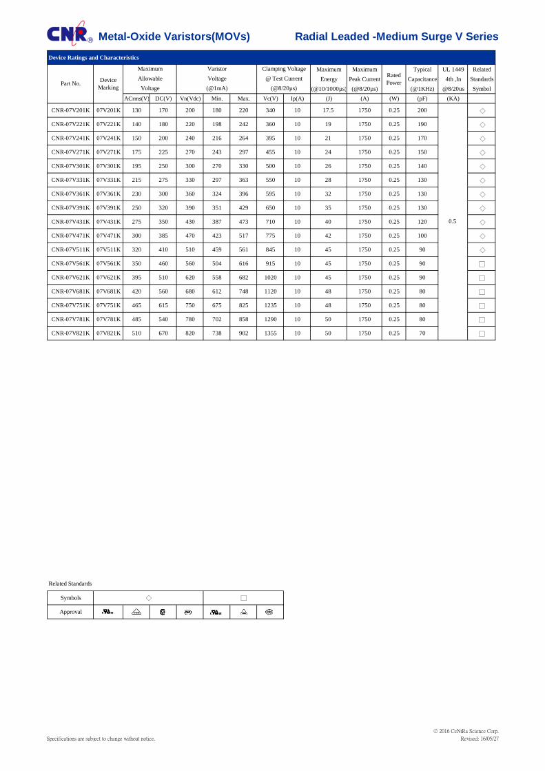
Metal-Oxide Varistors(MOVs) Radial Leaded -Medium Surge V Series
Device Ratings and Characteristics
Maximum Maximum Typical UL 1449 Related
Energy Peak Current Capacitance 4th ,In Standards
(@10/1000µs) (@8/20µs) (@1KHz) @8/20us Symbol
ACrms(V) DC(V) Vn(Vdc) Min. Max. Vc(V) Ip(A) (J) (A) (W) (pF) (KA)
CNR-07V201K 07V201K 130 170 200 180 220 340 10 17.5 1750 0.25 200 ◇
CNR-07V221K 07V221K 140 180 220 198 242 360 10 19 1750 0.25 190 ◇
CNR-07V241K 07V241K 150 200 240 216 264 395 10 21 1750 0.25 170 ◇
CNR-07V271K 07V271K 175 225 270 243 297 455 10 24 1750 0.25 150 ◇
CNR-07V301K 07V301K 195 250 300 270 330 500 10 26 1750 0.25 140 ◇
CNR-07V331K 07V331K 215 275 330 297 363 550 10 28 1750 0.25 130 ◇
CNR-07V361K 07V361K 230 300 360 324 396 595 10 32 1750 0.25 130 ◇
CNR-07V391K 07V391K 250 320 390 351 429 650 10 35 1750 0.25 130 ◇
CNR-07V431K 07V431K 275 350 430 387 473 710 10 40 1750 0.25 120 ◇
CNR-07V471K 07V471K 300 385 470 423 517 775 10 42 1750 0.25 100 ◇
CNR-07V511K 07V511K 320 410 510 459 561 845 10 45 1750 0.25 90 ◇
CNR-07V561K 07V561K 350 460 560 504 616 915 10 45 1750 0.25 90 □
CNR-07V621K 07V621K 395 510 620 558 682 1020 10 45 1750 0.25 90 □
CNR-07V681K 07V681K 420 560 680 612 748 1120 10 48 1750 0.25 80 □
CNR-07V751K 07V751K 465 615 750 675 825 1235 10 48 1750 0.25 80 □
CNR-07V781K 07V781K 485 540 780 702 858 1290 10 50 1750 0.25 80 □
CNR-07V821K 07V821K 510 670 820 738 902 1355 10 50 1750 0.25 70 □
Symbols
Approval
@ Test CurrentRated
PowerPart No.Device
Marking
Maximum Varistor Clamping Voltage
Allowable Voltage
◇ □
Related Standards
Voltage (@1mA) (@8/20µs)
0.5
Specifications are subject to change without notice.
© 2016 CeNtRa Science Corp.
Revised: 16/05/27

Metal-Oxide Varistors(MOVs) Radial Leaded -Medium Surge V Series
Device Ratings and Characteristics
Maximum Maximum Typical UL 1449 Related
Energy Peak Current Capacitance 4th ,In Standards
(@10/1000µs) (@8/20µs) (@1KHz) @8/20us Symbol
ACrms(V) DC(V) Vn(Vdc) Min. Max. Vc(V) Ip(A) (J) (A) (W) (pF) (KA)
CNR-10V201K 10V201K 130 170 200 180 220 340 25 35 3500 0.4 430 ◇
CNR-10V221K 10V221K 140 180 220 198 242 360 25 39 3500 0.4 410 ◇
CNR-10V241K 10V241K 150 200 240 216 264 395 25 42 3500 0.4 380 ◇
CNR-10V271K 10V271K 175 225 270 243 297 455 25 49 3500 0.4 350 ◇
CNR-10V301K 10V301K 195 250 300 270 330 500 25 55 3500 0.4 330 ◇
CNR-10V331K 10V331K 215 275 330 297 363 550 25 58 3500 0.4 300 ◇
CNR-10V361K 10V361K 230 300 360 324 396 595 25 65 3500 0.4 300 ◇
CNR-10V391K 10V391K 250 320 390 351 429 650 25 70 3500 0.4 300 ◇
CNR-10V431K 10V431K 275 350 430 387 473 710 25 80 3500 0.4 270 ◇
CNR-10V471K 10V471K 300 385 470 423 517 775 25 85 3500 0.4 230 ◇
CNR-10V511K 10V511K 320 410 510 459 561 845 25 92 3500 0.4 210 ◇
CNR-10V561K 10V561K 350 460 560 504 616 915 25 92 3500 0.4 200 □
CNR-10V621K 10V621K 395 510 620 558 682 1020 25 95 3500 0.4 180 □
CNR-10V681K 10V681K 420 560 680 612 748 1120 25 98 3500 0.4 150 □
CNR-10V751K 10V751K 465 615 750 675 825 1235 25 100 3500 0.4 140 □
CNR-10V781K 10V781K 485 540 780 702 858 1290 25 100 3500 0.4 140 □
CNR-10V821K 10V821K 510 670 820 738 902 1355 25 110 3500 0.4 140 □
CNR-10V911K 10V911K 550 745 910 819 1001 1500 25 130 3500 0.4 130 □
CNR-10V102K 10V102K 625 825 1000 900 1100 1650 25 140 3500 0.4 130 □
CNR-10V112K 10V112K 680 895 1100 990 1210 1815 25 155 3500 0.4 120 □
Symbols
Approval
◇
Related Standards
□
2
Maximum Varistor Clamping Voltage
Allowable Voltage @ Test CurrentPart No.
Device
Marking Voltage (@1mA) (@8/20µs)
Rated
Power
Specifications are subject to change without notice.
© 2016 CeNtRa Science Corp.
Revised: 16/05/27

Metal-Oxide Varistors(MOVs) Radial Leaded -Medium Surge V Series
Device Ratings and Characteristics
Maximum Maximum Typical UL 1449 Related
Energy Peak Current Capacitance 4th ,In Standards
(@10/1000µs) (@8/20µs) (@1KHz) @8/20us Symbol
ACrms(V) DC(V) Vn(Vdc) Min. Max. Vc(V) Ip(A) (J) (A) (W) (pF) (KA)
CNR-14V201K 14V201K 130 170 200 180 220 340 50 84 6000 0.6 770 ◇
CNR-14V221K 14V221K 140 180 220 198 242 360 50 91 6000 0.6 740 ◇
CNR-14V241K 14V241K 150 200 240 216 264 395 50 98 6000 0.6 700 ◇
CNR-14V271K 14V271K 175 225 270 243 297 455 50 112 6000 0.6 640 ◇
CNR-14V301K 14V301K 195 250 300 270 330 500 50 123 6000 0.6 600 ◇
CNR-14V331K 14V331K 215 275 330 297 363 550 50 133 6000 0.6 580 ◇
CNR-14V361K 14V361K 230 300 360 324 396 595 50 147 6000 0.6 540 ◇
CNR-14V391K 14V391K 250 320 390 351 429 650 50 161 6000 0.6 500 ◇
CNR-14V431K 14V431K 275 350 430 387 473 710 50 182 6000 0.6 450 ◇
CNR-14V471K 14V471K 300 385 470 423 517 775 50 196 6000 0.6 400 ◇
CNR-14V511K 14V511K 320 410 510 459 561 845 50 210 6000 0.6 350 ◇
CNR-14V561K 14V561K 350 460 560 504 616 915 50 231 6000 0.6 350 □
CNR-14V621K 14V621K 395 510 620 558 682 1020 50 252 6000 0.6 330 □
CNR-14V681K 14V681K 420 560 680 612 748 1120 50 266 6000 0.6 310 □
CNR-14V751K 14V751K 465 615 750 675 825 1235 50 280 6000 0.6 300 □
CNR-14V781K 14V781K 485 640 780 702 858 1290 50 280 6000 0.6 300 □
CNR-14V821K 14V821K 510 670 820 738 902 1355 50 280 6000 0.6 270 □
CNR-14V911K 14V911K 550 745 910 819 1001 1500 50 308 6000 0.6 260 □
CNR-14V102K 14V102K 625 825 1000 900 1100 1650 50 336 6000 0.6 250 □
CNR-14V112K 14V112K 680 895 1100 990 1210 1815 50 364 6000 0.6 240 □
Symbols
Approval
◇
Related Standards
□
3
Maximum Varistor Clamping Voltage
Allowable Voltage @ Test CurrentPart No.
Device
Marking Voltage (@1mA) (@8/20µs)
Rated
Power
Specifications are subject to change without notice.
© 2016 CeNtRa Science Corp.
Revised: 16/05/27
LIAO
螢光標示

Metal-Oxide Varistors(MOVs) Radial Leaded -Medium Surge V Series
Device Ratings and Characteristics
Maximum Maximum Typical UL 1449 Related
Energy Peak Current Capacitance 4th ,In Standards
(@10/1000µs) (@8/20µs) (@1KHz) @8/20us Symbol
ACrms(V) DC(V) Vn(Vdc) Min. Max. Vc(V) Ip(A) (J) (A) (W) (pF) (KA)
CNR-20V201K 20V201K 130 170 200 180 220 340 100 140 10000 1 1700 ◇
CNR-20V221K 20V221K 140 180 220 198 242 360 100 155 10000 1 1600 ◇
CNR-20V241K 20V241K 150 200 240 216 264 395 100 170 10000 1 1500 ◇
CNR-20V271K 20V271K 175 225 270 243 297 455 100 190 10000 1 1300 ◇
CNR-20V301K 20V301K 195 250 300 270 330 500 100 215 10000 1 1200 ◇
CNR-20V331K 20V331K 215 275 330 297 363 550 100 228 10000 1 1100 ◇
CNR-20V361K 20V361K 230 300 360 324 396 595 100 255 10000 1 1100 ◇
CNR-20V391K 20V391K 250 320 390 351 429 650 100 275 10000 1 1100 ◇
CNR-20V431K 20V431K 275 350 430 387 473 710 100 303 10000 1 1000 ◇
CNR-20V471K 20V471K 300 385 470 423 517 775 100 350 10000 1 900 ◇
CNR-20V511K 20V511K 320 410 510 459 561 845 100 382 10000 1 800 ◇
CNR-20V561K 20V561K 350 460 560 504 616 915 100 382 10000 1 750 □
CNR-20V621K 20V621K 395 510 620 558 682 1020 100 400 10000 1 570 □
CNR-20V681K 20V681K 420 560 680 612 748 1120 100 420 10000 1 550 □
CNR-20V751K 20V751K 465 615 750 675 825 1235 100 420 10000 1 530 □
CNR-20V781K 20V781K 485 640 780 702 858 1290 100 440 10000 1 500 □
CNR-20V821K 20V821K 510 670 820 738 902 1355 100 460 10000 1 500 □
CNR-20V911K 20V911K 550 745 910 819 1001 1500 100 510 10000 1 480 □
CNR-20V102K 20V102K 625 825 1000 900 1100 1650 100 565 10000 1 460 □
CNR-20V112K 20V112K 680 895 1100 990 1210 1815 100 620 10000 1 400 □
Symbols
Approval
◇
5
□
Maximum Varistor Clamping Voltage
Allowable Voltage @ Test Current
Related Standards
Part No.Device
Marking Voltage (@1mA) (@8/20µs)
Rated
Power
Specifications are subject to change without notice.
© 2016 CeNtRa Science Corp.
Revised: 16/05/27

Metal-Oxide Varistors(MOVs) Radial Leaded -Medium Surge V Series
Characteristics Standard Test condition / Methods Specifications
Single peak current IEC 61051-1
The maximum current within the varistor voltage
change of ±10% with the standard impulse current
(8/20μs) applied one times.
△V1mA/V1mA≦±10%
Nominal discharge
current testUL 1449 4th
Refer to UL 1449 4th item 41.1, the test condition is
8/20µs surge current waveform for 15 times.
△V1mA/V1mA≦ ±10%
No visible damage
Multiple pulse
capabilityIEC 61051-1 Refer to Impulse life rating curve 100 times current.
△V1mA/V1mA≦ ±10%
No visible damage
Energy IEC 61051-1
The maximum energy within the varistor voltage
change of±10% when one impulse of 2 ms or 10/1000
μs is applied.
△V1mA/V1mA≦±10%
Robustness of
Terminations
(Tensile)
IEC 60068-2-21
After Gradually applying the specified force and keep
the unit fixed for 10±1 sec.
Terminal diameter Force
Ø 0.6 mm 9.8 N ( 1.0Kgf )
Ø 0.8 mm 9.8 N ( 1.0Kgf )
Ø 1.0 mm 19.6 N ( 2.0Kgf )
No visible damage
Robustness of
Terminations
(Bending)
IEC 60068-2-21
Hold specimen and apply the force specified below to
each lead. Bendthe specimen to 90°, then return to the
original position. Repeat theprocedure in the opposite
direction.
Terminal diameter Force
Ø 0.6 mm 9.8 N ( 0.5Kgf )
Ø 0.8 mm 9.8 N ( 0.5Kgf )
Ø 1.0 mm 19.6 N ( 1.0Kgf )
No visible damage
Solderability IEC 60068-2-20
After dipping the terminals to a depth of approximately
3mm from the body in a soldering bath of 260±5℃ for
2±0.5 seconds, the terminal shall be visually examined.
Approximately 95% of the terminal
shall be covered with solder uniformly
Resistance to
Soldering HeatIEC 60068-2-20 260±5℃, 10±1 sec.
△V1mA/V1mA≦±5%,
No visible damage
Vibration IEC 60068-2-6
Frequency range: 10-55Hz
Amplitude: 0.75mm or 98 m/s²
Direction: 3 mutually perpendicular directions, 2 hrs
each.
△V1mA/V1mA≦5%
No visible damage
High Temperature
StorageIEC 60068-2-2 125±2 ℃ x 1000 ±24hrs △VmA/VmA≦±5%
High Humidity
StorageIEC 60068-2-2 40±2 ℃, 90 to 95% RH 1000 hrs △V1mA/△V1mA≦±5%
Temperature Cycle IEC 60068-2-14
The conditions shown below shall be repeated 5 cycles.
Step Temperature (℃) Period (minutes)
1. -40±3 30±3
2. Room temperature 15±3
3. 125±2 30±3
4. Room temperature 15±3
△V1mA/V1mA≦±5%
No visible damage
High Temp Load IEC 61051-185±2 ℃ , 1000±24hrs. At Vdc or Vrms
(MAX. Allowable Voltage)△V1mA/V1mA≦±10%
Withstanding
Voltage
(Body Insulation)
The specified voltage shall be applied both terminals of
the specimen connected together and metal foil closely
wrapped round its body for 1 minute.Electrical
breakdown shall be examined.
Classification Test Voltage
V1mA≦68V 1000Vrms
V1mA > 68V 2500Vrms
No visible damage
Reliability
Specifications are subject to change without notice.
© 2016 CeNtRa Science Corp.
Revised: 16/05/27

Metal-Oxide Varistors(MOVs) Radial Leaded -Medium Surge V Series
Power Derating Curve
Surge Current Standard Waveform
Should transients occur in rapid succession, the average power dissipation is the energy (watt-seconds) per pulse times the number of pulses
per second. The power so developed must be with the specifications shown on the Device Ratings and Specifications Table for the specific
device.The operating values of a MOV need to be derated at high temperatures as shown above. Because varistors only dissipate a relatively
small amount of average power they are not suitable for repetitive applications that involve substantial amounts of average power dissipation.
.
O1 = Virtual Origin of Wave
T = Time from 10% to 90% of Peak
T1 = Rise Time = 1.25 x T
T2 = Decay Time
Example - For an 8/20 μs Current Waveform:
8μs = T1 = Rise Time
20μs = T2 = Decay Time
Specifications are subject to change without notice.
© 2016 CeNtRa Science Corp.
Revised: 16/05/27

Metal-Oxide Varistors(MOVs) Radial Leaded -Medium Surge V Series
Product Dimensions
Dimension Table Unit:mm
Min. Max. Min. Max. Min. Max. Min. Max. Min. Max. Min. Max.
5.5 7.5 7.5 9.0 10.5 14.0 13.5 17.5 18.5 23.0 19.5 25.0
- 10.0 - 12.0 - 17.0 - 20.5 - 26.0 - 28.0
4.0 6.0 4.0 6.0 6.5 8.5 6.5 8.5 6.5 8.5 9.0 11.0
0.58 0.62 0.58 0.62 0.78 0.82 0.78 0.82 0.78 0.98 0.98 1.02
0.8 1.6 0.8 1.6 1.0 1.8 1.0 1.8 1.0 1.8 1.0 1.8
180K-271K - 13.0 - 15.0 - 19.5 - 22.5 - 26.5 - 30.0
>271K - 13.0 - 15.0 - 20.5 - 23.5 - 27.0 - 31.0
*Short Cut Lead type TTXX the lead length (L) can 3.0~15mm (expect 20V<10mm), see Ordering Note.
**a value see T max. table
3.0
25.0
See Tmax table
Ø d
T
A(max.)
P(max.)
L(min)
K(Kink Lead)
H
W
07V 10V05VModel size
Symbol
D
14V 20V18V
D
HL
W
T
P
D
A
W
T
P
L
Φd Φd
D
A
W
T
P
L
Φd
D
AL
W
T
Φd
K
K
Fig 1. Straght Lead Fig 2. Outside Kink Lead
Fig 3. Inside Kink Lead Fig 4. In Line Kink Lead
P
a
a
a
W
a
Bottom view
W
a
W
a
Bottom view
Bottom view
Specifications are subject to change without notice.
© 2016 CeNtRa Science Corp.
Revised: 16/05/27

Metal-Oxide Varistors(MOVs) Radial Leaded -Medium Surge V Series
T max. Table Unit:mm
Model 05V 07V 10V 14V 18V 20V a(±1.0) Model 05V 07V 10V 14V 18V 20V a(±1.0)
201K 3.3 3.5 3.9 4.0 4.2 4.3 1.5 511K 4.8 5.0 5.3 5.4 5.6 5.7 2.6
221K 3.4 3.6 4.0 4.1 4.3 4.4 1.6 561K 5 5.2 5.5 5.6 5.8 5.9 2.8
241K 3.5 3.7 4.1 4.2 4.4 4.5 1.7 621K 5.3 5.5 5.7 5.8 6.0 6.1 3.1
271K 3.7 3.9 4.2 4.3 4.5 4.6 1.8 681K 5.4 5.6 5.8 5.9 6.1 6.2 3.3
301K 3.9 4.1 4.3 4.4 4.6 4.7 1.9 751K 5.6 5.8 6.0 6.1 6.3 6.4 3.6
331K 4 4.2 4.5 4.6 4.8 4.9 2.0 781K - 6.0 6.3 6.4 6.6 6.7 3.8
361K 4.1 4.3 4.7 4.8 5.0 5.1 2.1 821K - 6.3 6.5 6.6 6.8 6.9 4.0
391K 4.2 4.4 4.8 4.9 5.1 5.2 2.3 911K - - 6.6 6.7 6.9 7.0 4.3
431K 4.4 4.6 5.0 5.1 5.3 5.4 2.4 102K - - 7.0 7.1 7.3 7.4 4.6
471K 4.6 4.8 5.2 5.3 5.5 5.6 2.5 112K - - 7.4 7.5 7.7 7.9 5.2
Specifications are subject to change without notice.
© 2016 CeNtRa Science Corp.
Revised: 16/05/27

Metal-Oxide Varistors(MOVs) Radial Leaded -Medium Surge V Series
Tape and Reel Specificstions
● Radial devices on tape are supplied with straight leads,kinked leads or in -line leads
05V 07V 10V 10V 14V 14V
P 12.7±1.0 12.7±1.0 12.7±1.0 15.0±1.0 25.4±1.0 30.0±1.0
P0 12.7±0.2 12.7±0.2 12.7±0.2 15.0±0.2 12.7±0.2 15.0±0.2
P1 3.85±0.7 3.85±0.7 3.85±0.7 3.75±0.7 8.95±0.7 3.75±0.7
P2 6.35±0.7 6.35±0.7 6.35±0.7 7.5±0.7 12.7±0.7 7.5±0.7
F 5.0±0.8 5.0±0.8 7.5±0.8 7.5±0.8 7.5±0.8 7.5±0.8
△h 2.0max 2.0max 2.0max 2.0max 2.0max 2.0max
18.0+1.0 18.0+1.0 18.0+1.0 18.0+1.0 18.0+1.0 18.0+1.0
18.0-0.5 18.0-0.5 18.0-0.5 18.0-0.5 18.0-0.5 18.0-0.5
W0 5.0 Min. 5.0 Min. 5.0 Min. 5.0 Min. 5.0 Min. 5.0 Min.
9.0+0.75 9.0+0.75 9.0+0.75 9.0+0.75 9.0+0.75 9.0+0.75
9.0-0.5 9.0-0.5 9.0-0.5 9.0-0.5 9.0-0.5 9.0-0.5
W2 3.0 Max 3.0 Max 3.0 Max 3.0 Max 3.0 Max 3.0 Max
18.0+2.0 18.0+2.0 18.0+2.0 18.0+2.0 18.0+2.0 18.0+2.0
18.0-0.0 18.0-0.0 18.0-0.0 18.0-0.0 18.0-0.0 18.0-0.0
H0 16.0±0.5 16.0±0.5 16.0±0.5 16.0±0.5 16.0±0.5 16.0±0.5
H1 32.0 Max. 32.0 Max. 36.0 Max. 36.0 Max. 40.0 Max. 40.0 Max.
D0 4.0±0.2 4.0±0.2 4.0±0.2 4.0±0.2 4.0±0.2 4.0±0.2
t 0.7±0.2 0.7±0.2 0.7±0.2 0.7±0.2 0.7±0.2 0.7±0.2
L 11.0 Max 11.0 Max 11.0 Max 11.0 Max 11.0 Max 11.0 Max
Figure A, D A, D B, E A, D C F
Tape WidthW
Hold Down Tape Width
Total Tape Thickness
HHeight from Tape Center to Component
Base
W1 Hole Position
Component Alignment
Model SizeDescriptionSymbol
Pitch of Component
Feed Hole Pitch
Feed Hole Center to Pitch
Hole Center to Component Center
Lead to Lead Distance
Leagth Clipped Lead
Hold Down Tape Position
Seating Plane Height
Component Height
Feed Hole Diameter
Specifications are subject to change without notice.
© 2016 CeNtRa Science Corp.
Revised: 16/05/27

Metal-Oxide Varistors(MOVs) Radial Leaded -Medium Surge V Series
Tape and Reel Specificstions
● Radial devices on tape are supplied with straight leads,kinked leads or in -line leads
05V 07V 10V 10V 14V 14V
P 12.7±1.0 12.7±1.0 12.7±1.0 15.0±1.0 25.4±1.0 30.0±1.0
P0 12.7±0.2 12.7±0.2 12.7±0.2 15.0±0.2 12.7±0.2 15.0±0.2
P1 3.85±0.7 3.85±0.7 3.85±0.7 3.75±0.7 8.95±0.7 3.75±0.7
P2 6.35±0.7 6.35±0.7 6.35±0.7 7.5±0.7 12.7±0.7 7.5±0.7
F 5.0±0.8 5.0±0.8 7.5±0.8 7.5±0.8 7.5±0.8 7.5±0.8
△h 2.0max 2.0max 2.0max 2.0max 2.0max 2.0max
18.0+1.0 18.0+1.0 18.0+1.0 18.0+1.0 18.0+1.0 18.0+1.0
18.0-0.5 18.0-0.5 18.0-0.5 18.0-0.5 18.0-0.5 18.0-0.5
W0 5.0 Min. 5.0 Min. 5.0 Min. 5.0 Min. 5.0 Min. 5.0 Min.
9.0+0.75 9.0+0.75 9.0+0.75 9.0+0.75 9.0+0.75 9.0+0.75
9.0-0.5 9.0-0.5 9.0-0.5 9.0-0.5 9.0-0.5 9.0-0.5
W2 3.0 Max 3.0 Max 3.0 Max 3.0 Max 3.0 Max 3.0 Max
18.0+2.0 18.0+2.0 18.0+2.0 18.0+2.0 18.0+2.0 18.0+2.0
18.0-0.0 18.0-0.0 18.0-0.0 18.0-0.0 18.0-0.0 18.0-0.0
H0 16.0±0.5 16.0±0.5 16.0±0.5 16.0±0.5 16.0±0.5 16.0±0.5
H1 32.0 Max. 32.0 Max. 36.0 Max. 36.0 Max. 40.0 Max. 40.0 Max.
D0 4.0±0.2 4.0±0.2 4.0±0.2 4.0±0.2 4.0±0.2 4.0±0.2
t 0.7±0.2 0.7±0.2 0.7±0.2 0.7±0.2 0.7±0.2 0.7±0.2
L 11.0 Max 11.0 Max 11.0 Max 11.0 Max 11.0 Max 11.0 Max
Figure A, D A, D B, E A, D C F
Seating Plane Height
Hole Center to Component Center
Lead to Lead Distance
Component Alignment
Tape Width
Hold Down Tape Width
Hole Position
Hold Down Tape Position
Height from Tape Center to Component
Base
Component Height
Leagth Clipped Lead
Feed Hole Diameter
Total Tape Thickness
W
W1
H
Model Size
Pitch of Component
Feed Hole Pitch
Feed Hole Center to Pitch
Symbol Description
Specifications are subject to change without notice.
© 2016 CeNtRa Science Corp.
Revised: 16/05/27

Metal-Oxide Varistors(MOVs) Radial Leaded -Medium Surge V Series
Packing information
Bulk packing
Tape & Reel product packing
Box product packing
Serise L±5 W±5 H±5
CNR-05~07 340 245 45
CNR-10~14 340 245 50
700
CNR-14V(681K~112K)-TRXX 600
CNR-18V 500 500
2000
1500
800
CNR-07V(180K~391K)-TRXX
CNR-07V(431K~821K)-TRXX
CNR-10V(180K~621K)-TRXX
CNR-10V(681K~112K)-TRXX
1000
800
Series Quantity (pcs/box)
56
CNR-14V(180K~391K)-TRXX
CNR-14(V431K~621K)-TRXX
CNR-05V(681K~751K)-BTXX
CNR-10V(681K~112K)-BTXX
CNR-14V(180K~621K)-BTXX
1000
800
800
500
CNR-05V(180K~621K)-BTXX
CNR-14V(681K~112K)-BTXX 400
CNR-07V(180K~621K)-BTXX 1000
CNR-07V(681K~821K)-BTXX 800
CNR-10V(180K~621K)-BTXX 1000
Cut Lead Type
Quantity(pcs/bag)
500
2000
1500
500
500
250
Quantity (pcs/reel)
250
CNR-14V 500
43
CNR-20V 250
Series A (mm)
CNR-05V(180K~391K)-TRXX
CNR-05V(431K~751K)-TRXX
CNR-10V 500 500 500
Kink Type
Quantity(pcs/bag)
CNR-07V 1000 1000 1000
CNR-05V 1000 1000 1000
Series
Straight Lead
Type
Quantity(pcs/bag)
Specifications are subject to change without notice.
© 2016 CeNtRa Science Corp.
Revised: 16/05/27

Metal-Oxide Varistors(MOVs) Radial Leaded -Medium Surge V Series
Recommendation Reworking Conditions with Soldering Iron
RoHS Compliant Declaration
We hereby declare that the components delivered to your company are
compliant with RoHS Directive 2002/95/EC
Storage Conditions of Products
(Ι) Storage Conditions:
1.Storage Temperature: -10℃~+40℃
2.Relative Humidity:≦75%RH
3.Keep away from corrosive atmosphere and sunlight
4.Solvent Resistance: MIL–STD–202, Method 215F
5.Moisture Sensitivity: Level 1, J-STD-020
(ΙΙ) Period of Storage: 1 year
Distance from Varistor 2mm(Min)
Item Conditions
Temperature of soldering Iron-tip 360℃(Max)
Soldering Time 3 sec(Max)
Solder Recommendation
Specifications are subject to change without notice.
© 2016 CeNtRa Science Corp.
Revised: 16/05/27

Metal-Oxide Varistors(MOVs) Radial Leaded -Medium Surge V Series
Explanation of Part Numbers
OPTION CODES
(See Ratings & Specifications tables and notes below) (See notes below)
C N R - X X V X X X K
Device Family Code
CeNtRa
Metal Oxide Varistors
Disc Element Dia.
05 - Ø 5.0mm 14 - Ø 14mm
07 - Ø 7.0mm 18 - Ø 18mm
10 - Ø 10mm 20 - Ø 20mm
Type Tolerance
D: Standard series C: Automobile series K=±10%
V: Medium surge series F: Thermal Cut-off Series Varistor Voltage
P: High surge series T: Thermal Cut-off with indictor Series 180=18X100=18V
H: Ultra high energy series 181=18X101=180V
N: High temperature series 182=18X102=1800V
Ordering Notes:
MAIN PART CODES
Series + /Packaging/ Lead Style / Designators: Option Code
Ordering examples: + XXX
CeNtRa V Series varistors are shipped standard in bulk pack with straight leads or Kink lead and lead spacing outlined in the Package Dimensions
section of this data sheet. Contact your CeNtRa sales representative to discuss non-standard options.
CNR-10V471KTRIX CNR-10V471KBTIX
Inside Kink Lead
Bulk Pack
Inside Kink Lead
(Short Cut) Bulk Pack
Inside Kink Lead
Tape & Reel Pack
Inside Kink Lead
Flat Box Pack
CNR-10V471K CNR-10V471KTTSXXX CNR-10V471KTRSX CNR-10V471KBTSX CNR-10V471KTTS10
A: P0 → 12.7mm±0.2mm
B: P0 → 15.0mm±0.2mm
Straight Lead
Bulk Pack (Standard)
Straight Lead
(Short Cut) Bulk Pack
CNR-10V471KSHK CNR-10V471KTTHXXX CNR-10V471KTRHX CNR-10V471KBTHX
CNR-10V471KTRSA
CNR-10V471KTRSB
CNR-10V471SOK CNR-10V471KTTKXXX CNR-10V471KTRKX CNR-10V471KBTKX
In Line Kink Lead
Bulk Pack
In Line Kink Lead
(Short Cut) Bulk Pack
In Line Kink Lead
Tape& Reel Pack
In Line Kink Lead
Flat Box Pack
CNR-10V471KSIK CNR-10V471KTTIXXX
Straight Lead
Tape & Reel Pack
Straight Lead
Flat Box Pack
Short Cut Lead
Length 10mm±1.0mm
MAIN PART CODES
TTK XXX
For standard parts, use the MAIN
PART designator only. For parts with
non-standard options (such as
additional form, Packing and lead
space options), use MAIN PART +
OPTION CODE.
OPTION CODE items are subject to
availability and minimum order
requirements. Please contact a Centra
products representative for additional
information or questions.
Outside Kink Lead Bulk
Pack
Outside Kink Lead
(Short Cut) Bulk Pack
Outside Kink Lead
Tape & Reel Pack
Outside Kink Lead
Flat Box Pack
Tape & Reel Pack
Feed Hole Pitch
Specifications are subject to change without notice.
© 2016 CeNtRa Science Corp.
Revised: 16/05/27