Metal-hybrid structures for an improved crash behaviour of car
18
Metal-hybrid structures for an improved crash behaviour of car body structures Michael Kriescher, Walid Salameh, Deutsches Zentrum für Luft- und Raumfahrt e.V. (DLR), DE Dr. Alexander Droste, Jan Röttger, DOW Automotive Systems 18. Mai 2010 »Materialien des Karosseriebaus«
Transcript of Metal-hybrid structures for an improved crash behaviour of car

Metal-hybrid structures for an improved crashbehaviour of car body structures
Michael Kriescher, Walid Salameh, Deutsches Zentrum für Luft- und Raumfahrt e.V. (DLR), DEDr. Alexander Droste, Jan Röttger, DOW Automotive Systems
18. Mai 2010 »Materialien des Karosseriebaus«
Materialien des Karosseriebaus 18.05.2010, Folie 2
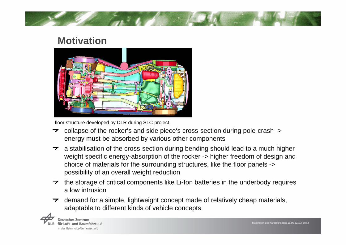
Motivation
collapse of the rocker‘s and side piece‘s cross-section during pole-crash -> energy must be absorbed by various other componentsa stabilisation of the cross-section during bending should lead to a much higher weight specific energy-absorption of the rocker -> higher freedom of design and choice of materials for the surrounding structures, like the floor panels -> possibility of an overall weight reductionthe storage of critical components like Li-Ion batteries in the underbody requires a low intrusiondemand for a simple, lightweight concept made of relatively cheap materials, adaptable to different kinds of vehicle concepts
floor structure developed by DLR during SLC-project

Materialien des Karosseriebaus 18.05.2010, Folie 3
Basic principle
Absorption of crash energy through elongation of material
Stabilisation of cross section
stabilisation of the beam by a core structurethe core must stay intact, throughout the entire bending process, in order to increase weight specific energy absorptionsimplified LS-Dyna-calculations showed an increase in weight specific energy absorption by a factor of about 2,5
Variant Drawing Total mass [kg]
Material Energy absorption [kJ]
kJ/kg
Core: foam 400 kg/m³shell: 1 mm TRIPLEX
22,39Various types of steel
4,5 0,2
Al honeycomb
15,15
Core: 1 mm Al; shell: 1 mm TRIPLEX
5,8 0,38
Reference
0,5
Foam
28,1 14
Materialien des Karosseriebaus 18.05.2010, Folie 4
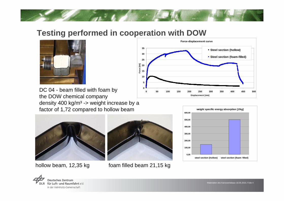
Testing performed in cooperation with DOWForce-displacement curve
0
5
10
15
20
25
30
35
0 50 100 150 200 250 300 350 400 450 500Displacement [mm]
Forc
e [k
N]
Steel section (hollow)
Steel section (foam-filled)
hollow beam, 12,35 kg foam filled beam 21,15 kg
DC 04 - beam filled with foam bythe DOW chemical companydensity 400 kg/m³ -> weight increase by a factor of 1,72 compared to hollow beam weight specific energy absorption [J/kg]
0,00
100,00
200,00
300,00
400,00
500,00
600,00
steel section (hollow) steel section (foam- filled)
Materialien des Karosseriebaus 18.05.2010, Folie 5
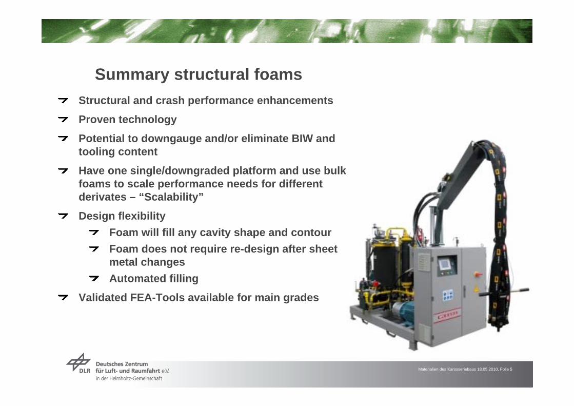
Summary structural foamsStructural and crash performance enhancements
Proven technology
Potential to downgauge and/or eliminate BIW and tooling content
Have one single/downgraded platform and use bulk foams to scale performance needs for different derivates – “Scalability”
Design flexibilityFoam will fill any cavity shape and contourFoam does not require re-design after sheet metal changesAutomated filling
Validated FEA-Tools available for main grades

Materialien des Karosseriebaus 18.05.2010, Folie 6
Cavity filling with BETAFOAM™
BETAFOAM™ is a family of foam-based products
Two-component polyurethane foam applied as bulk
Fat cycle time, room temperature curing
Components form a rigid, closed cell foamFoam products range in density from 32 g/l to 641 g/l
Higher density foams provide multi-functional benefits
Materialien des Karosseriebaus 18.05.2010, Folie 7
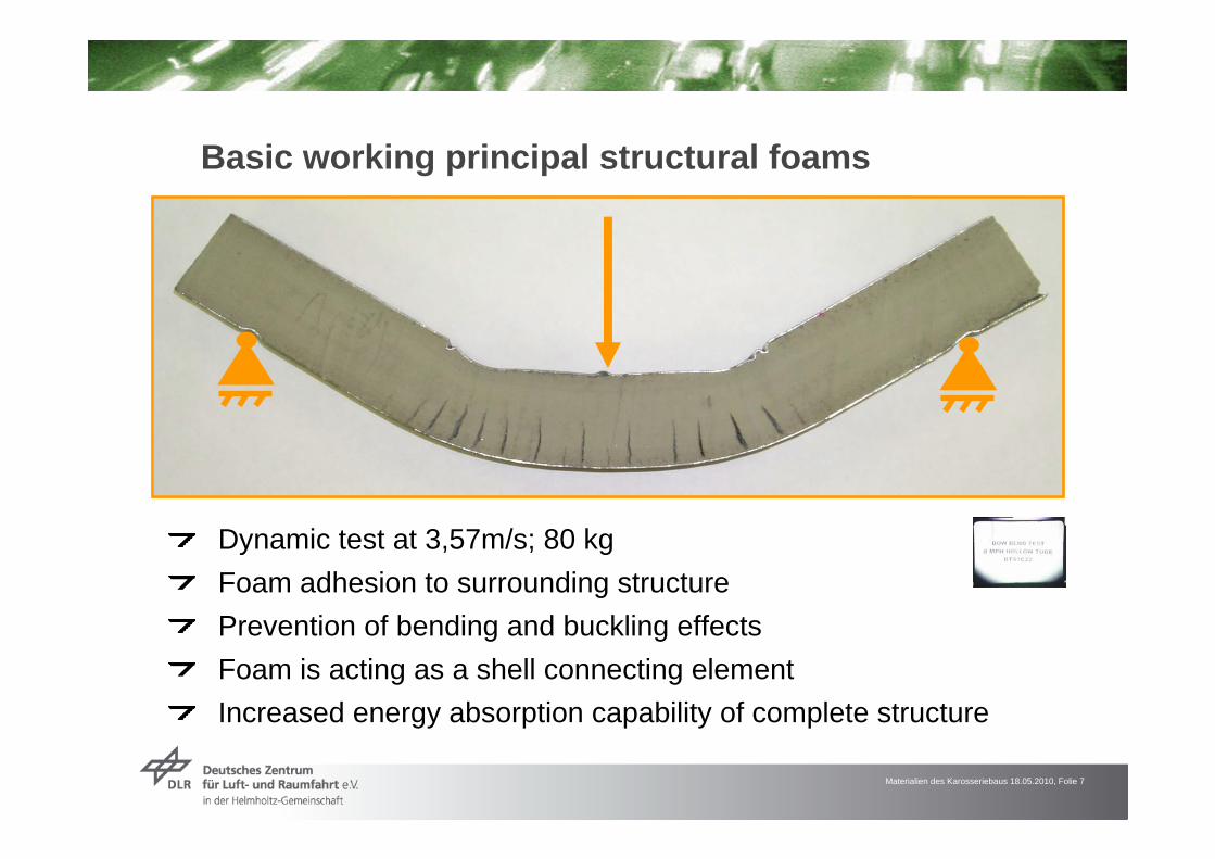
Basic working principal structural foams
Dynamic test at 3,57m/s; 80 kgFoam adhesion to surrounding structurePrevention of bending and buckling effectsFoam is acting as a shell connecting elementIncreased energy absorption capability of complete structure

Materialien des Karosseriebaus 18.05.2010, Folie 8
v0 CAEv0 Test
v1 CAEv1 Test
v2 CAEv2 Test
v3 CAEv3 Test
Boundary Prescribed Motion Moving Rigid Wall
v1 < v2 < v3
Static Correlation Dynamic Correlation
Material model – Development and validation
Static CAE
Static TEST 1
Static TEST 3
Static TEST 0
Static TEST 2
Static TEST 0Static CAE
Static TEST 1
(mm)
Foam-Filled Tube
Empty Tube
Static CAE
Static TEST 1
Static TEST 3
Static TEST 0
Static TEST 2
Static TEST 0Static CAE
Static TEST 1
(mm)
Foam-Filled Tube
Empty Tube

Materialien des Karosseriebaus 18.05.2010, Folie 9
Geometric variations
Force-displacement curve
0
5
10
15
20
25
30
35
40
45
0 50 100 150 200 250 300 350 400 450 500
Displacement [mm]
Forc
e [k
N]
Steel section (hollow)
Steel section (foam-filled)
Steel section (sideways, foam-filled)
deformation mode stays the same for different cross sectionstest with a crosssection rotated by 90 ° leads to higher peak force but earlier failure of the material -> steel with a higher max. strain would lead to even better results

Materialien des Karosseriebaus 18.05.2010, Folie 10
Variation of foam density
foam density 200 kg/m³ -> weight increaseby a factor of 1,37 compared to a hollowbeaminsufficient stabilisation of the steel shelldue to use of low density foam -> no significant gain in weight specific energyabsorption
weight specific energy absorption [J/kg]
0
100
200
300
400
500
600
DC04 hollowsection
DC04 + foam 400 DC04 + foam 200
Force-displacement curve
05
101520253035
0 100 200 300 400 500Displacement [mm]
Forc
e [k
N]
steel section DC 04 with foam 400 kg/m³
steel DC04 with foam 200 kg/m³
steel section DC 04 hollow

Materialien des Karosseriebaus 18.05.2010, Folie 11
core remains intact, and partiallystabilises the beam
large foldbeneath thecore
H3 H2 H1
Variation of core material
use of wooden cores: high ratio of compression strength / densityhigher density than foam
further development: combination of solid corestructures and light foam
Force-displacement curve
0
5
10
15
20
25
0 50 100 150 200 250 300 350 400 450 500Displacement [mm]
Forc
e [k
N]
DC04_H1DC04_H2DC04_H3
Materialien des Karosseriebaus 18.05.2010, Folie 12
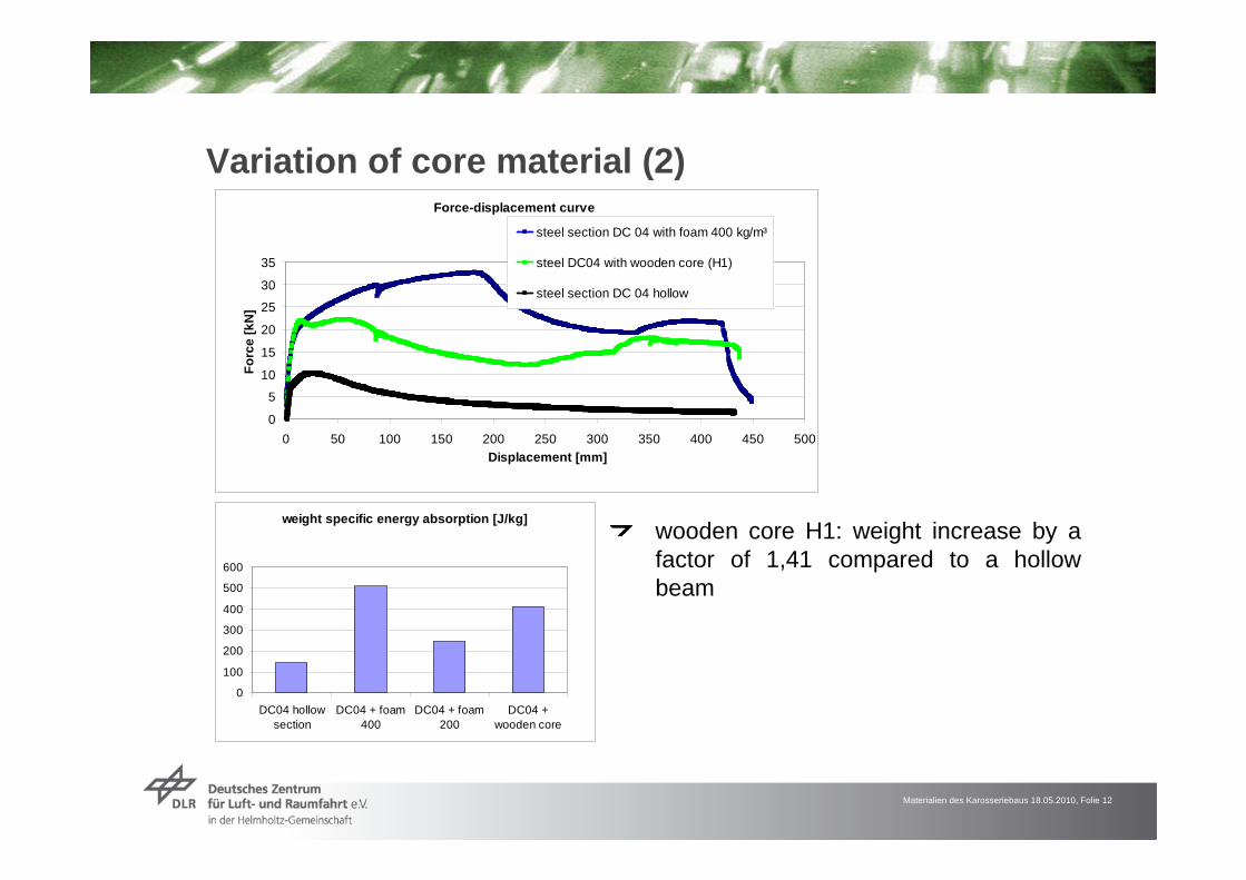
Variation of core material (2)
wooden core H1: weight increase by a factor of 1,41 compared to a hollowbeam
weight specific energy absorption [J/kg]
0
100
200
300
400
500
600
DC04 hollowsection
DC04 + foam400
DC04 + foam200
DC04 +wooden core
Force-displacement curve
0
5
10
15
20
25
30
35
0 50 100 150 200 250 300 350 400 450 500Displacement [mm]
Forc
e [k
N]
steel section DC 04 with foam 400 kg/m³
steel DC04 with wooden core (H1)
steel section DC 04 hollow

Materialien des Karosseriebaus 18.05.2010, Folie 13
Variation of shell material
use of stainless steel 1.4301 (highertensile strength) -> weight increaseby a factor of 1,74 compared to hollow beam
weight specific energy absorption [J/kg]
0
100
200
300
400
500
600
700
800
900
DC04 hollowsection
DC04 + foam400
DC04 + foam200
DC04 + woodencore
1.4301+ foam400
Force-displacement curve
05
1015202530354045
0 50 100 150 200 250 300 350 400 450 500Displacement [mm]
Forc
e [k
N]steel section DC 04 with foam 400 kg/m³
steel section DC 04 hollow
steel section 1.4301 with foam 400 kg/m³

Materialien des Karosseriebaus 18.05.2010, Folie 14
Integration into the underbody structure, basic principle
conventional rectangular topology:
difficulty in designing an appropriate support structure
a ring-like shaped, filled structure should lead to comparatively low strain values, distributed over a large portion of the structure
Materialien des Karosseriebaus 18.05.2010, Folie 15
LS-Dyna-Simulation results with a simplified body structure
modified pole crash:
the modified pole crash was performed to avoid the addition of virtual weights
car body is fixedweight of pole= 1380 kgspeed of pole = 29 km/hintrusion is slightly more severe compared to a regular pole crash

Materialien des Karosseriebaus 18.05.2010, Folie 16
Modified pole crash results with a simplified body structure
results of the new structure:high energy absorption, compared to a full vehicle with interior, even without floor panel, seat structure etc.proof of the basic principle: the underbody structure is deformed as one „ring“, without any collapse of particular parts

Materialien des Karosseriebaus 18.05.2010, Folie 17
Summary and conclusions
filling of beam structures drastically increase their intrusion resistenceand weight -specific energy-absorptionan underbody structure composed of a ring-like filled structure results in a very high intrusion resistance during pole crash. A large portion of the underbody could therefore be used for the storage of critical components like Li-Ion batteriesa more detailed car body structure is needed to make accurate weight predictionsoptimization of the structure by decreasing intrusion resistance in favor of reduced weight seems reasonable since the frame structure alone absorbs all of the crash energy, other components, like the floor panel, can be designed differently, leading to a potential weight reduction

Thank you for your attention