
METAL FOAMS FOR ELECTROMAGNETICS: EXPERI- MENTAL ...
18
Progress In Electromagnetics Research B, Vol. 45, 1–18, 2012 METAL FOAMS FOR ELECTROMAGNETICS: EXPERI- MENTAL, NUMERICAL AND ANALYTICAL CHARAC- TERIZATION L. Catarinucci * , G. Monti, and L. Tarricone Innovation Engineering Department, University of Salento, Via per Monteroni, Lecce 73100, Italy Abstract—This work focuses on the use of metal foams, a relatively new class of materials, for high added-value electromagnetic (EM) shields. First, the Shielding Effectiveness (SE) of aluminum foam slabs is experimentally evaluated, showing very good shielding properties. Successively, accurate numerical models of metal foams are proposed and used in a proprietary Variable-Mesh Parallel Finite Difference Time Domain code, in order to characterize the EM properties of slabs of such materials. Afterwards, a third approach is adopted. It consists in the application of the effective medium theories in order to obtain an analytical EM model of the metal foams; this way, their SE can be evaluated with a negligible computational time by using common mathematical tools. Finally, a methodology to design/analyze customized metal foams for EM shield applications is suggested. It takes advantage from the joint use of the numerical and analytical presented approaches, thus allowing a computationally efficient evaluation of SE and other electromagnetic properties of metal foams. Results demonstrate the suitability of metal foam structures for effective EM shielding in many industrial applications, as well as the accuracy of the proposed analytical and numerical approaches. 1. INTRODUCTION Metal foams represent a relatively new class of materials which opens new challenging perspectives in many industrial applications. In fact, metal foams are heterogeneous cellular structures made of metal and gas (usually air) characterized by a very low apparent density [1– 11]. This gives foams high stiffness-to-weight ratio and lightweight. Received 29 August 2012, Accepted 12 October 2012, Scheduled 16 October 2012 * Corresponding author: Luca Catarinucci ([email protected]).
Transcript of METAL FOAMS FOR ELECTROMAGNETICS: EXPERI- MENTAL ...
Progress In Electromagnetics Research B, Vol. 45, 1–18, 2012
METAL FOAMS FOR ELECTROMAGNETICS: EXPERI-MENTAL, NUMERICAL AND ANALYTICAL CHARAC-TERIZATION
L. Catarinucci*, G. Monti, and L. Tarricone
Innovation Engineering Department, University of Salento, Via perMonteroni, Lecce 73100, Italy
Abstract—This work focuses on the use of metal foams, a relativelynew class of materials, for high added-value electromagnetic (EM)shields. First, the Shielding Effectiveness (SE) of aluminum foam slabsis experimentally evaluated, showing very good shielding properties.Successively, accurate numerical models of metal foams are proposedand used in a proprietary Variable-Mesh Parallel Finite DifferenceTime Domain code, in order to characterize the EM properties ofslabs of such materials. Afterwards, a third approach is adopted.It consists in the application of the effective medium theories inorder to obtain an analytical EM model of the metal foams; thisway, their SE can be evaluated with a negligible computational timeby using common mathematical tools. Finally, a methodology todesign/analyze customized metal foams for EM shield applications issuggested. It takes advantage from the joint use of the numericaland analytical presented approaches, thus allowing a computationallyefficient evaluation of SE and other electromagnetic properties of metalfoams. Results demonstrate the suitability of metal foam structuresfor effective EM shielding in many industrial applications, as well asthe accuracy of the proposed analytical and numerical approaches.
1. INTRODUCTION
Metal foams represent a relatively new class of materials which opensnew challenging perspectives in many industrial applications. In fact,metal foams are heterogeneous cellular structures made of metal andgas (usually air) characterized by a very low apparent density [1–11]. This gives foams high stiffness-to-weight ratio and lightweight.
Received 29 August 2012, Accepted 12 October 2012, Scheduled 16 October 2012* Corresponding author: Luca Catarinucci ([email protected]).
2 Catarinucci, Monti, and Tarricone
(a) (b)
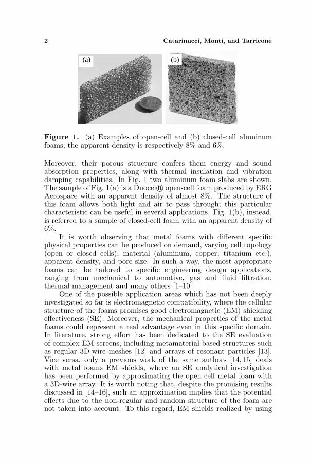
Figure 1. (a) Examples of open-cell and (b) closed-cell aluminumfoams; the apparent density is respectively 8% and 6%.
Moreover, their porous structure confers them energy and soundabsorption properties, along with thermal insulation and vibrationdamping capabilities. In Fig. 1 two aluminum foam slabs are shown.The sample of Fig. 1(a) is a Duocel R© open-cell foam produced by ERGAerospace with an apparent density of almost 8%. The structure ofthis foam allows both light and air to pass through; this particularcharacteristic can be useful in several applications. Fig. 1(b), instead,is referred to a sample of closed-cell foam with an apparent density of6%.
It is worth observing that metal foams with different specificphysical properties can be produced on demand, varying cell topology(open or closed cells), material (aluminum, copper, titanium etc.),apparent density, and pore size. In such a way, the most appropriatefoams can be tailored to specific engineering design applications,ranging from mechanical to automotive, gas and fluid filtration,thermal management and many others [1–10].
One of the possible application areas which has not been deeplyinvestigated so far is electromagnetic compatibility, where the cellularstructure of the foams promises good electromagnetic (EM) shieldingeffectiveness (SE). Moreover, the mechanical properties of the metalfoams could represent a real advantage even in this specific domain.In literature, strong effort has been dedicated to the SE evaluationof complex EM screens, including metamaterial-based structures suchas regular 3D-wire meshes [12] and arrays of resonant particles [13].Vice versa, only a previous work of the same authors [14, 15] dealswith metal foams EM shields, where an SE analytical investigationhas been performed by approximating the open cell metal foam witha 3D-wire array. It is worth noting that, despite the promising resultsdiscussed in [14–16], such an approximation implies that the potentialeffects due to the non-regular and random structure of the foam arenot taken into account. To this regard, EM shields realized by using

Progress In Electromagnetics Research B, Vol. 45, 2012 3
aluminum foam slabs could have a true added value. Let’s considerfirst magnetic resonance apparata: the structure of the open-cell foamslabs has the advantage to let air and light pass through, thus reducingclaustrophobic discomfort. The same kind of aluminum foams could beattractive for the realization of air-vents in EM shielded environmentsand also in industrial microwave ovens, where the need to reducehumidity could be easily satisfied. Furthermore, the high vibrationdamping capabilities and sound absorption properties of closed-cellfoams become interesting for the EM shielding of engines.
The evident opportunities of application of these materials inElectromagnetics make their rigorous EM characterization a must [11].Accordingly, in this work, the analysis of the shielding propertiesof different kinds of Duocel R© aluminum foam slabs has beenfirstly performed through experimental measurements by varyingporosity and apparent density. The obtained interesting shieldingcapabilities encourage the development of ad-hoc simulation tools fordesign/analysis purposes.
From a numerical point of view, the EM problem of the rigorousevaluation of the SE metal foams is a challenging task; metal foamshave a complex structure, strongly inhomogeneous, thus requiringsophisticated numerical models. The first proposed solution is basedon the generation of accurate Finite Difference Time Domain (FDTD)-compatible numerical models, and on their use in a proprietary parallelVariable Mesh (VM) FDTD algorithm [17–24]. In this way, the hugecomputational requirement due to the intrinsic different length-scalesin the simulation domain (for instance, fractions of millimeters for thefoam ligaments and tens of centimeters for the antenna-foam distance),can be satisfied. Nevertheless, despite of the advantages in terms ofaccuracy given by the full-wave tool, the computational time is in somecases excessive and the hardware cost not negligible.
In order to overcome these shortcomings, a simplified andeffective analytical EM model of metal foams has been developed bycarrying on an effective medium approach. Differently from the fully-analytical approach presented in [14–16], in this work the 3D-wiremesh approximation is not applied anymore and the peculiarities of thefoam structure are taken into account by feeding the model throughthe full-wave simulation of a small numerical foam sample. For theestimation of metal foam SE, the proposed strategy can be directlyimplemented in common mathematical tools and executed with anegligible computational time. Moreover, such a model is also usefulfor general EM design and analysis purposes. In fact, if combined witha conventional full-wave simulator, it guarantees adequate accuracywith an affordable computational effort.

4 Catarinucci, Monti, and Tarricone
2. METAL FOAMS
Although the use of metal foams in innovative mechanical and thermalapplications has been steadily increasing over the past decade, foamsare quite unfamiliar to other engineering sectors. Nevertheless,the previously mentioned perspective of application in the EMarea encourages a detailed EM characterization, taking into accountrelevant issues such as the metal type, the cell topology (closed oropen), the apparent density and the cell size. More specifically,apparent density represents the weight per unit volume of a material,including voids existing in the material itself. It influences foamstiffness, strength, and both electrical and thermal conductivity. As forthe pore size, it represents the pore dimension and it is the parameterwhich mostly affects properties such as optical capacity and fluid flowresistance. The number of pores for linear inches (PPI) is also aparameter used to characterize the foam. Such physical characteristicsare intrinsically dependent on the foam manufacturing process and itis worth highlighting that they are strongly related to each other.
Without loss of generality, the foam deeply studied in this paper,potentially very attractive for EM applications, is the one produced byERG Aerospace and named Duocel R© foam. This material consists ofsmall ligaments that are continuously connected in an open-celled foamstructure (see Fig. 1(a)). The cells of Duocel R© foams are generally12 or 14-sided polyhedral whose pentagonal or hexagonal faces areformed by five or six ligaments. The open window in each of these facesdefines the pore diameter which usually varies from 5 to 100 PPI. Asreported in [1], the manufacturing technology is quite sophisticated andit is substantially based on the realization of a preliminary open-cellpolymer foam mould template with the desired cell size and apparentdensity. The polymer is then coated with a mould casting slurry whichis then dried and embedded in casting sand. The mould is then bakedin order to harden the casting material as well as to decompose andevaporate the polymer template, thus giving a negative image of thefoam. This mould is subsequently filled with a metal alloy and cooled,so that a metal with an equivalent shape of the original polymer foamis obtained.
By realizing appropriate foams with specific values of PPI (andconsequently of pore sizes) and apparent density, it is possible to obtaina combination of properties considered attractive from an EM point ofview.
Progress In Electromagnetics Research B, Vol. 45, 2012 5
3. EM SIMULATION TOOLS FOR METAL FOAMS
As already stated, in order to electromagnetically characterize themetal foam structures, a full wave simulator based on the very versatileFDTD algorithm, can be used. Nevertheless, in order to describethe complex foams structure accurately, space step of fractions ofmillimeters must be used, thus requiring huge computational efforts.Fine space steps, in fact, cause the FDTD time step reduction as well asthe excessive growing of the simulation domain size. In the followingsubsections, a proprietary parallel VM-FDTD algorithm, capable todeal with non uniform meshes in parallel environment, will be brieflyillustrated. Moreover, a realistic and very accurate numerical model ofmetal foams will be realized and presented.
Despite of the achieved accuracy, a less computational intensiveapproach is necessary in order to allow the adoption of traditionalcomputing platforms. Therefore, an analytical model is also proposed.
3.1. Parallel VM-FDTD
When using uniform FDTD, the characterization of simulated objectswith an adequate space resolution obliges the use of such a resolutionover the entire simulation domain. This leads to the adoption of aspace discretization step larger than the one needed in several partsof the simulation domain. Such an observation is the basis of VM-FDTD algorithms [17–23], which, allowing the existence of differentdiscretization steps in different regions, give a good level of accuracyfor the solution using less memory and computational power than theones needed to obtain the same accuracy with a classical (uniform)FDTD scheme. Moreover, when such a scheme is implemented in aparallel platform, further advantages in terms of computational timeare achieved. In fact, differently from standard subgridding techniques,the variable mesh scheme is a natural extension of the parallel FDTDimplementation. In VM-FDTD the discretization is performed in away that each grid cell has only one adjacent grid cell for each oneof its six faces. Furthermore, along each direction the space stepcan be arbitrarily varied, within the limits imposed by the stabilitycriterion, allowing very smooth transitions between a fine and a coarsemesh region. For such reasons, the parallel implementation is basedon the same principles of the parallel uniform FDTD, i.e., it adoptsthe same partition of the simulation domain, based on a balancing ofthe computation among the different processors, and implements thesame communication pattern between adjacent processors.
In order to take into account the different cell-size, three auxiliaryvectors can be used, containing the dimension of each cell along x, y
6 Catarinucci, Monti, and Tarricone
and z. Because of the component location in Yee’s cell [23], such valuescan be directly used wherever E-field space derivatives are evaluated;on the contrary, when H-field space derivatives are considered, theaveraged dimension between two adjacent cells must be used. The samekind of arrangement must be applied when computing the absorbingboundary condition as well [23, 24].
3.2. Metal Foams Numerical Models
An FDTD-compatible numerical model of metal foams has beendeveloped, consisting in a binary file that associates the generic spacecoordinate to the related kind of material (air or aluminum alloyin most cases). In order to accurately reproduce in the FDTDsimulation domain the complex and non-regular geometry of metalfoams, appropriate algorithms have been developed. Such algorithmsemulate the actual metal foam realization procedure described in theprevious section. Using this approach, both open and closed-cellnumerical models of metal foams can be generated with arbitraryporosity and apparent density. More specifically, the implementedalgorithms are based on the generation, in a certain number of randompoints, of pores of a desired shape (which can be a sphere, but alsoan open polyhedral when Duocel R© foams are modeled): cell sizeand windows apertures are randomly varied in specified ranges andthe intersections between the pores are accurately treated. The finalresult is a file in the so-called voxel format, where each voxel is acube, individuated by three Cartesian coordinates, which containsinformation about the material in that voxel (aluminum or air in theaddressed case).
(a) (b)
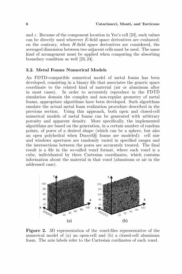
Figure 2. 3D representation of the voxel-files representative of thenumerical model of (a) an open-cell and (b) a closed-cell aluminumfoam. The axis labels refer to the Cartesian cordinates of each voxel.
Progress In Electromagnetics Research B, Vol. 45, 2012 7
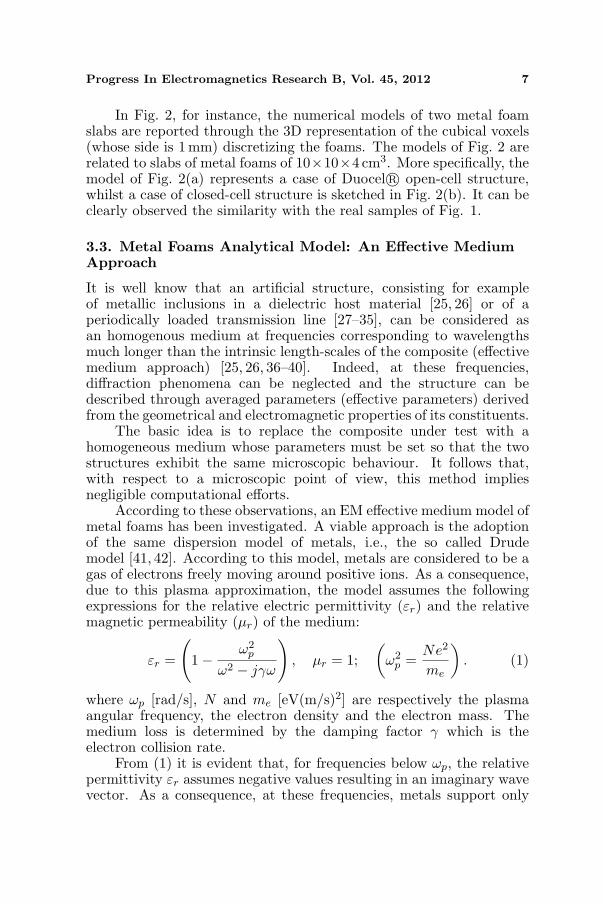
In Fig. 2, for instance, the numerical models of two metal foamslabs are reported through the 3D representation of the cubical voxels(whose side is 1 mm) discretizing the foams. The models of Fig. 2 arerelated to slabs of metal foams of 10×10×4 cm3. More specifically, themodel of Fig. 2(a) represents a case of Duocel R© open-cell structure,whilst a case of closed-cell structure is sketched in Fig. 2(b). It can beclearly observed the similarity with the real samples of Fig. 1.
3.3. Metal Foams Analytical Model: An Effective MediumApproach
It is well know that an artificial structure, consisting for exampleof metallic inclusions in a dielectric host material [25, 26] or of aperiodically loaded transmission line [27–35], can be considered asan homogenous medium at frequencies corresponding to wavelengthsmuch longer than the intrinsic length-scales of the composite (effectivemedium approach) [25, 26, 36–40]. Indeed, at these frequencies,diffraction phenomena can be neglected and the structure can bedescribed through averaged parameters (effective parameters) derivedfrom the geometrical and electromagnetic properties of its constituents.
The basic idea is to replace the composite under test with ahomogeneous medium whose parameters must be set so that the twostructures exhibit the same microscopic behaviour. It follows that,with respect to a microscopic point of view, this method impliesnegligible computational efforts.
According to these observations, an EM effective medium model ofmetal foams has been investigated. A viable approach is the adoptionof the same dispersion model of metals, i.e., the so called Drudemodel [41, 42]. According to this model, metals are considered to be agas of electrons freely moving around positive ions. As a consequence,due to this plasma approximation, the model assumes the followingexpressions for the relative electric permittivity (εr) and the relativemagnetic permeability (µr) of the medium:
εr =
(1− ω2
p
ω2 − jγω
), µr = 1;
(ω2
p =Ne2
me
). (1)
where ωp [rad/s], N and me [eV(m/s)2] are respectively the plasmaangular frequency, the electron density and the electron mass. Themedium loss is determined by the damping factor γ which is theelectron collision rate.
From (1) it is evident that, for frequencies below ωp, the relativepermittivity εr assumes negative values resulting in an imaginary wavevector. As a consequence, at these frequencies, metals support only
8 Catarinucci, Monti, and Tarricone
evanescent modes. For common metals, typical values of ωp are in theTHz range.
In the last years, a large number of studies have demonstratedthat the frequency dependence given in (1) can be assumed to modelthe effective electric permittivity of artificial structures consisting of ametallic wire mesh [43–48]. Specifically, it has been experimentallyverified that an array of thin wires behaves like the metal whichconstitutes the wires, but with a lower plasma frequency [43–48].
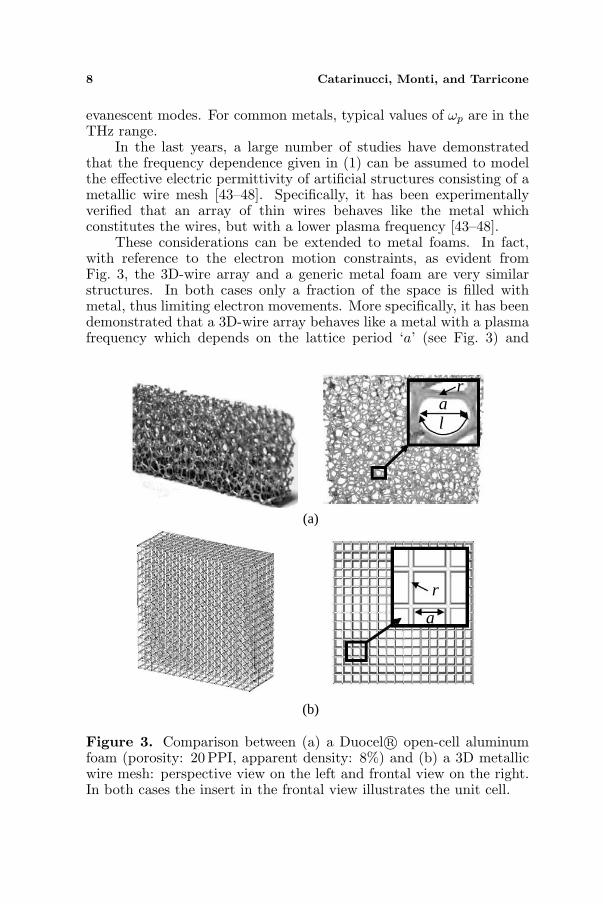
These considerations can be extended to metal foams. In fact,with reference to the electron motion constraints, as evident fromFig. 3, the 3D-wire array and a generic metal foam are very similarstructures. In both cases only a fraction of the space is filled withmetal, thus limiting electron movements. More specifically, it has beendemonstrated that a 3D-wire array behaves like a metal with a plasmafrequency which depends on the lattice period ‘a’ (see Fig. 3) and
(a)
(b)
ral
a
r
Figure 3. Comparison between (a) a Duocel R© open-cell aluminumfoam (porosity: 20PPI, apparent density: 8%) and (b) a 3D metallicwire mesh: perspective view on the left and frontal view on the right.In both cases the insert in the frontal view illustrates the unit cell.
Progress In Electromagnetics Research B, Vol. 45, 2012 9
on the wire radius (r) [49]. According to these considerations, metalfoams can be modeled like a metal with a plasma frequency dependingon their apparent density which, referring to Fig. 3, is related to thegeometric parameters a, r and l. It is expected that, as for a 3D-wiregrid, lower values of the metal foam apparent density correspond tolower values of the plasma frequency.
In order to prove such considerations, Equation (1) has beenused to calculate the SE of a metal foam slab of thickness d. Morespecifically, the SEdB of a slab can be obtained as the sum of threecontributions. The first one is the reflection by the two interfaces(air-foam and foam-air), called return loss and commonly indicatedas R. The second one is the attenuation of the transmitted wave,called absorption loss and commonly indicated as A. Finally, the thirdcontribution is given by the multiple reflection/transmission effect,called multiple-reflection and — transmission loss and commonlyindicated as M .
Consequently, SE can be evaluated as:
SEAnalytical,dB = SEAnalytical,dB (ωp, γ) = RdB + AdB + MdB. (2)
According to [12, 50], the parameters R, A, and M , are given by:
R = (Z0+Zs)2
4Z0Zs
A = exp (ikd)M =
[1− (Z0−Zs)
2
(Z0+Zs)2
]exp (i2kd)
(3)
where d [m] is the thickness of the slab, k [m−1] is the wave number inthe medium, Zs and Z0 [Ω] are respectively the intrinsic impedanceof the medium and the free space impedance: k = k0
√εrµr =
ωc0
√µr(1− ω2
p
ω2−jγω), Zs =
√µε = Z0√
1− ω2p
ω2−jγω
, c0 = 3 ∗ 108[ms ],
Z0 = 377 Ω.It is worth underlining that, by adopting a 3D-wire mesh
approximation, ωp and γ could be evaluated as a function of thegeometric parameters of the foam, as suggested and demonstrated bythe same authors in [14–16]. As clarified later on, in this paper analternative simplified approach is suggested, so as to take into accountthe peculiarities of the foam structure.
4. RESULTS
In this section, results related to the experimental, the numerical andthe analytical evaluation of the SE of different kinds of Duocel R©
10 Catarinucci, Monti, and Tarricone
30
50
70
90
110
130
1E+07 1E+08 1E+09 1E+10 1E+11
SE
[d
B]
Frequency [Hz]
Type I
Type IIType III
Type IV
Type V
70
80
90
100
5,0E+8 7,0E+8 9,0E+8 1,1E+9 1,3E+9 1,5E+9
SE
[d
B]
Frequency [Hz]
Type IType II
Type IIIType IV
Type V
(a)
(b)
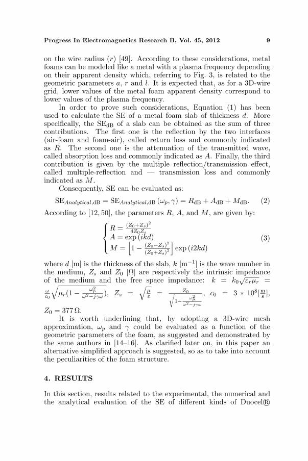
Figure 4. Shielding effectiveness (E field) for aluminum foam slabsdescribed in Table 1. (a) Numeriacal results (Tipe V) are betterhighlited in (b) the zoommed picture.
Table 1. Examined foam types.
Duocel R© Aluminum foams
Type I Type II Type III Type IV
Type V
(numerical
model)
10PPI, 6–8%
nominal
density, 6.1%
actual density.
Alloy 6101-F
20PPI, 6–8%
nominal
density, 8.5%
actual density.
Alloy 6101-F
40PPI, 6–8%
nominal
density, 7.9%
actual density.
Alloy 6101-F
40 PPI, 6-8%
nominal
density, 8.7%
actual density.
Alloy 6101-F
7 PPI, 11%
actual density,
numerically
generated
Alloy 6101-F
aluminum foam slabs are reported and discussed. In Fig. 4, forinstance, the electric SE related to five open-cell slabs with a thicknessof 1.4 cm is given for different structural properties (according to datasummarized in Table 1). More specifically, type I-IV foams have
Progress In Electromagnetics Research B, Vol. 45, 2012 11
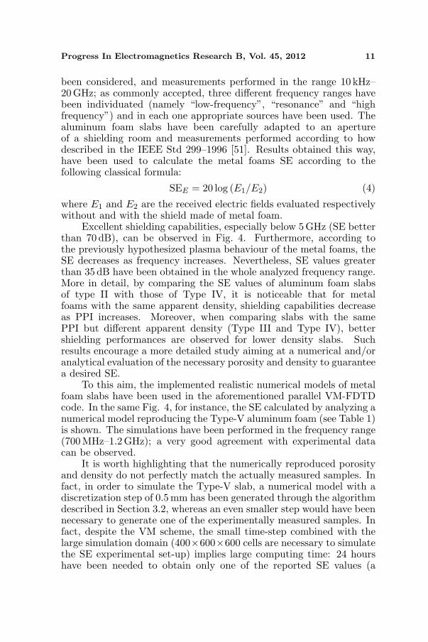
been considered, and measurements performed in the range 10 kHz–20GHz; as commonly accepted, three different frequency ranges havebeen individuated (namely “low-frequency”, “resonance” and “highfrequency”) and in each one appropriate sources have been used. Thealuminum foam slabs have been carefully adapted to an apertureof a shielding room and measurements performed according to howdescribed in the IEEE Std 299–1996 [51]. Results obtained this way,have been used to calculate the metal foams SE according to thefollowing classical formula:
SEE = 20 log (E1/E2) (4)
where E1 and E2 are the received electric fields evaluated respectivelywithout and with the shield made of metal foam.
Excellent shielding capabilities, especially below 5 GHz (SE betterthan 70 dB), can be observed in Fig. 4. Furthermore, according tothe previously hypothesized plasma behaviour of the metal foams, theSE decreases as frequency increases. Nevertheless, SE values greaterthan 35 dB have been obtained in the whole analyzed frequency range.More in detail, by comparing the SE values of aluminum foam slabsof type II with those of Type IV, it is noticeable that for metalfoams with the same apparent density, shielding capabilities decreaseas PPI increases. Moreover, when comparing slabs with the samePPI but different apparent density (Type III and Type IV), bettershielding performances are observed for lower density slabs. Suchresults encourage a more detailed study aiming at a numerical and/oranalytical evaluation of the necessary porosity and density to guaranteea desired SE.
To this aim, the implemented realistic numerical models of metalfoam slabs have been used in the aforementioned parallel VM-FDTDcode. In the same Fig. 4, for instance, the SE calculated by analyzing anumerical model reproducing the Type-V aluminum foam (see Table 1)is shown. The simulations have been performed in the frequency range(700MHz–1.2GHz); a very good agreement with experimental datacan be observed.
It is worth highlighting that the numerically reproduced porosityand density do not perfectly match the actually measured samples. Infact, in order to simulate the Type-V slab, a numerical model with adiscretization step of 0.5 mm has been generated through the algorithmdescribed in Section 3.2, whereas an even smaller step would have beennecessary to generate one of the experimentally measured samples. Infact, despite the VM scheme, the small time-step combined with thelarge simulation domain (400×600×600 cells are necessary to simulatethe SE experimental set-up) implies large computing time: 24 hourshave been needed to obtain only one of the reported SE values (a
12 Catarinucci, Monti, and Tarricone
30
50
70
90
110
130
1E+07 1E+08 1E+09 1E+10
SE [
dB]
Frequency [Hz]
Measured Data
Analytical Data
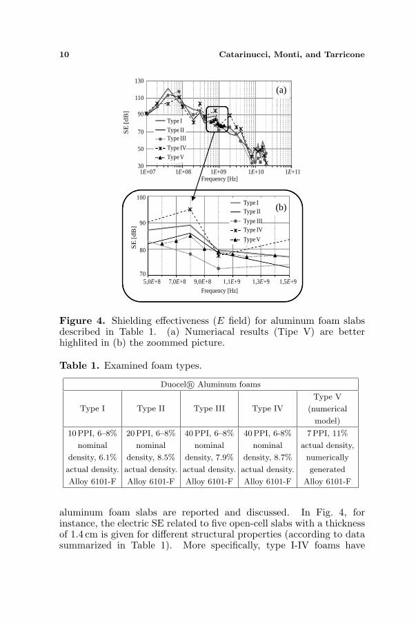
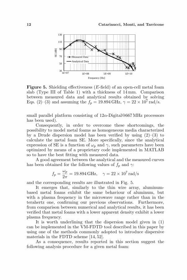
Figure 5. Shielding effectiveness (E-field) of an open-cell metal foamslab (Type III of Table 1) with a thickness of 14mm. Comparisonbetween measured data and analytical results obtained by solvingEqs. (2)–(3) and assuming the fp = 19.894GHz, γ = 22× 107 rad/s.
small parallel platform consisting of 12α-Digital@667MHz processorshas been used).
Consequently, in order to overcome these shortcomings, thepossibility to model metal foams as homogeneous media characterizedby a Drude dispersion model has been verified by using (2)–(3) tocalculate the metal foam SE. More specifically, since the analyticalexpression of SE is a function of ωp and γ, such parameters have beenoptimized by means of a proprietary code implemented in MATLABso to have the best fitting with measured data.
A good agreement between the analytical and the measured curveshas been obtained for the following values of fp and γ:
fp =ωp
2π= 19.894 GHz, γ = 22× 107 rad/s
and the corresponding results are illustrated in Fig. 5.It emerges that, similarly to the thin wire array, aluminum-
based metal foams exhibit the same behaviour of aluminum, butwith a plasma frequency in the microwave range rather than in theterahertz one, confirming our previous observations. Furthermore,from comparison between numerical and analytical results, it has beenverified that metal foams with a lower apparent density exhibit a lowerplasma frequency.
It is worth underlining that the dispersion model given in (1)can be implemented in the VM-FDTD tool described in this paper byusing one of the methods commonly adopted to introduce dispersivematerials in the FDTD scheme [14, 52].
As a consequence, results reported in this section suggest thefollowing analysis procedure for a given metal foam:
Progress In Electromagnetics Research B, Vol. 45, 2012 13
- Step 1 : analysis of a small sample of the metal foam numericalmodel by using a full-wave tool, such as the VM-FDTD.
- Step 2 : optimization of the ωp and γ parameters which appearin (1) in order to have the best fitting between the numericalsimulation results and the analytical data;
- Step 3 : use either directly (2)–(3) for the SE estimation orimplement (1) in a compatible full-wave simulator for differentEM investigations.
More specifically, it can be observed that the first step is referredto the numerical analysis of a relatively small sample of metal foam. Itis worth pointing out that, in this way, the analysis can be performedalso through traditional computers and common full-wave EM solvers.The numerical result of this pre-processing phase is used to feed theproposed simplified analytical model, thus allowing the evaluation ofoptimized values of ωp and γ parameters. In this way, differentlyfrom the approach proposed in [15], where the starting point for theevaluation of ωp and γ is derived from the 3D-wire mesh approximation,the foam peculiarities are taken into account. Finally, once theoptimization has been performed, the foam analytical model can beused to design/analyze even large EM problems involving metal foams.
5. CONCLUSION
In this work, the use of metal foams as high-added value EM shieldshas been addressed. Their excellent electromagnetic (EM) shieldingcapabilities have been verified through the Shielding Effectiveness (SE)measurement of different open-cell aluminum foam slabs. Furthermore,for design and analysis purposes, two different approaches have beenproposed. The former, based on a microscopic point of view, usesa powerful EM full-wave simulator to analyze ad-hoc developed andvery accurate numerical models of metal foams. Vice versa, the latteris based on a macroscopic point of view and looks at the foam asan effectively homogeneous medium. The accuracy of both numericaland analytical metal foam models has been demonstrated throughcomparisons with experimental data. Finally, a powerful methodologyto analyze general EM problems involving metal foams has beensuggested. It takes advantage from the joint use of the two presentedapproaches: the macroscopic parameters which electromagneticallycharacterize the foam are derived from a preliminary full-wave analysisof its numerical model. This way, by implementing the correspondingeffectively homogeneous medium in a common full-wave simulator, SEas well as other EM analysis can be easily performed.

14 Catarinucci, Monti, and Tarricone
REFERENCES
1. Ashby, M. F., A. G. Evans, N. A. Fleck, L. J. Gibson,J. W. Hutchinson, and H. N. G. Wadley, Metal Foams: A DesignGuide, Butterworth-Heinemann, 2000.
2. Kovacik, J., P. Tobolka, F. Simancik, J. Banhart, M. F. Ashby,and N. A. Fleck, “Metal foams and foam metal structures,” Int.Conf. Metfoam’99, MIT Verlag Bremen, Germany, Jun. 1999.
3. Banhart, J., “Manufacture characterisation and application ofcellular metals and metal foams,” Progress in Materials Science,Vol. 46, No. 6, 559–632, 2001.
4. Deshpande, V. S. and N. A. Fleck, “Isotropic constitutive modelsfor metallic foams,” Journal of the Mechanics and Physics ofSolids, Vol. 48, 1253–1283, 2000.
5. Hanssen, A. G., O. S. Hopperstad, M. Langseth, and H. Ilstad,“Validation of constitutive models applicable to aluminiumfoams,” International Journal of Mechanical Sciences, Vol. 44,359–406, 2002.
6. Lu, T. J. and J. M. Ong, “Characterization of close-celled cellularaluminium alloys,” Journal of Materials Science, Vol. 36, 2773–2786, 2001.
7. Bart-Smith, H., J. W. Hutchinson, N. A. Fleck, and A. G. Evans,“Influence of imperfections on the performance of metal foam coresandwich panels,” Int. Journal of Solid and Structures, Vol. 39,4999–5012, 2002.
8. Youssef, S., E. Maire, and R. Gaertner, “Finite element modelingof the actual structure of cellular materials determined by X-raytomography,” Acta Materialia, Vol. 53, 719–730, 2005.
9. Baumeister, J., U. J. Banhart, and M. Weber, “Aluminium foamsfor transport industry,” Materials & Design, Vol. 18, 217–220,1997.
10. Han, F. S. and Z. G. Zhu, “The mechanical behavior of foamedaluminum,” Journal of Materials Science, Vol. 34, 291–299, 1999.
11. Catarinucci, L., O. Losito, L. Tarricone, and F. Pagliara, “Highadded-value EM shielding by using metal-foams: Experimentaland numerical characterization,” IEEE Int. Symp. on Electromag-netic Compatibility, Vol. 2, 285–289, Aug. 2006.
12. Lovat, G. and P. Burghignoli, “Shielding effectiveness ofa metamaterial slab,” IEEE Int. Symp. on ElectromagneticCompatibility, 2007.
13. Boyvat, M. and C. Hafner, “Molding the flow of magnetic

Progress In Electromagnetics Research B, Vol. 45, 2012 15
field with metamaterials: Magnetic field shielding,” Progress InElectromagnetics Research, Vol. 126, 303–316, 2012.
14. Monti, G., L. Catarinucci, and L. Tarricone, “New materials forelectromagnetic shielding: Metal foams with plasma properties,”Microwave and Optical Technology Letters, Vol. 52, No. 8, 1700–1705, Aug. 2010.
15. Monti, G., L. Catarinucci, and L. Tarricone, “Metal foams forelectromagnetic shielding: A plasma model,” Proc. of EuropeanConference on Antennas and Propagation, EuCAP 2009, 2123–2126, 2009.
16. Monti, G., L. Catarinucci, and L. Tarricone, “Experimentalvalidation of a plasma model for electromagnetic metal foamshields,” IEEE MTT-S International Microwave SymposiumDigest, 145–148, 2009.
17. Catarinucci, L., P. Palazzari, and L. Tarricone, “A parallelvariable-mesh FDTD tool for the solution of large electromagneticproblems,” Proc. of 19th IEEE International Parallel andDistributed Processing Symposium, IPDPS 2005, Denver, CO,2005.
18. Catarinucci, L., P. Palazzari, and L. Tarricone, “Parallel FD-TD simulation of radiobase antennae,” Radiation ProtectionDosimetry, Vol. 97, No. 4, 409–413, 2001.
19. Catarinucci, L., P. Palazzari, and L. Tarricone, “A parallel FDTDtool for the solution of large dosimetric problems: An applicationto the interaction between humans and radiobase antennas,” IEEEMTT-S International Microwave Symposium Digest, Vol. 3, 1755–1758, 2002.
20. Catarinucci, L., P. Palazzari, and L. Tarricone, “Human exposureto the near field of radiobase antennas — A full-wave solutionusing parallel FDTD,” IEEE Transactions on Microwave Theoryand Techniques, Vol. 51, No. 3, 935–940, 2003.
21. De Donno, D., A. Esposito, L. Tarricone, and L. Catarinucci,“Introduction to GPU computing and CUDA programming:A case study on FDTD,” IEEE Antennas and PropagationMagazine, Vol. 52, No. 3, 116–122, 2010.
22. Catarinucci, L., P. Palazzari, and L. Tarricone, “On the useof numerical phantoms in the study of the human-antennainteraction problem,” IEEE Antennas and Wireless PropagationLetters, Vol. 2, 43–45, 2003.
23. Catarinucci, L. and L. Tarricone, “A parallel graded-mesh FDTDalgorithm for human-antenna interaction problems,” InternationalJournal of Occupational Safety and Ergonomics, Vol. 15, No. 1,

16 Catarinucci, Monti, and Tarricone
45–52, 2009.24. Taflove, A., Computational Electrodynamics: The Finite Differ-
ence Time-domain Method, Artech House, Norwood, MA, 1995.25. Shelby, R. A., D. R. Smith, S. C. Nemat-Nasser, and S. Schultz,
“Microwave transmission through a two-dimensional, isotropic,left-handed metamaterial,” Appl. Phys. Lett., Vol. 78, No. 4, 489–491, Jan. 2001.
26. Vendik, I., O. Vendik, I. Kolmakov, and M. Odit, “Modellingof isotropic double negative media for microwave applications,”Opto-Electronics Review, Vol. 14, No. 3, 179–186, 2006.
27. Monti, G. and L. Tarricone, “Negative group velocity ina split ring resonator-coupled microstrip line,” Progress InElectromagnetics Research, Vol. 94, 33–47, 2009.
28. Monti, G. and L. Tarricone, “Signal reshaping in a transmissionline with negative group velocity behaviour,” Microwave OpticalTechnology Letters, Vol. 51, No. 11, 2627–2633, 2009.
29. Monti, G. and L. Tarricone, “Dispersion analysis of a planarnegative group velocity transmission line,” Proceedings of the 37thEuropean Microwave Conference, EUMC, 1644–1647, 2007.
30. Monti, G. and L. Tarricone, “Compact broadband monolithic 3-dB coupler by using artificial transmission lines,” Microwave andOptical Technology Letters, Vol. 50, No. 10, 2662–2667, 2008.
31. Monti, G. and L. Tarricone, “Reduced-size broadband CRLH-ATL rat-race coupler,” Proceedings of the 36th EuropeanMicrowave Conference, EuMC 2006, 125–128, 2007.
32. Wang, C.-W., T.-G. Ma, and C.-F. Yang, “A new planarartificial transmission line and its applications to a miniaturizedbutler matrix,” IEEE Transactions on Microwave Theory andTechniques, Vol. 55, No. 12, 2792–2801, 2007.
33. Monti, G. and L. Tarricone, “Dual-band artificial transmissionlines branch-line coupler,” International Journal of RF andMicrowave Computer-Aided Engineering, Vol. 18, No. 1, 53–62,2008.
34. Monti, G., R. de Paolis, and L. Tarricone, “Design of a 3-statereconfigurable CRLH transmission line based on MEMS switches,”Progress In Electromagnetics Research, Vol. 95, 283–297, 2009.
35. Eccleston, K. W. and S. H. M. Ong, “Compact planar microstripline branch-line and rat race coupler couplers,” IEEE Transactionson Microwave Theory and Techniques, Vol. 51, No. 10, 2119–2125,Oct. 2003.
36. Monti, G. and L. Tarricone, “A novel theoretical formulation for

Progress In Electromagnetics Research B, Vol. 45, 2012 17
the analysis of the propagation of finite-bandwidth signals in adouble-negative slab,” Microwave and Optical Technology Letters,Vol. 47, No. 5, 434–439, 2005.
37. Monti, G. and L. Tarricone, “Gaussian pulse expansion ofmodulated signals in double-negative slab,” IEEE Transactionson Microwave Theory and Techniques, Vol. 54, No. 6, 2755–2761,2006.
38. Choy, T. C., Effective Medium Theory: Principles andApplications Clarendon, Oxford University Press, New York, 1999.
39. Monti, G. and L. Tarricone, “Dispersion analysis of an negativegroup velocity medium with MATLAB,” Applied ComputationalElectromagnetics Society Journal, Vol. 24, No. 5, 478–486,Oct. 2009.
40. Monti, G. and L. Tarricone, “On the propagation of a Gaussianpulse in a double-negative slab,” Proc. 35th European MicrowaveConference, 1419–1422, 2005.
41. Drude, P., Ann. Phys., Vol. 1, 566, Leipzig, 1900.42. Ashcroft, N. W. and N. D. Mermin, Solid State Physics, Saunders
Co., Philadelphia, 1976.43. Pendry, J. B., A. J. Holden, D. J. Robbins, and W. J. Stewart,
“Low frequency plasmons in thin-wire structures,” J. Phys.:Condens. Matter, Vol. 10, 4785–4809, 1998.
44. Silveirinha, M. G. and C. A. Fernandes, “Homogenization of 3-D-connected and nonconnected wire metamaterials,” IEEE Trans.on Microw. Theory and Techniques, Vol. 53, No. 4, Apr. 2005.
45. Maslovski, S. I., S. A. Tretyakov, and P. A. Belov, “Wiremedia with negative effective permittivity: A quasi static model,”Microwave Optical Technology Letters, Vol. 35, No. 1, 47–51,Oct. 2002.
46. Tretyakov, S., Analytical Modeling in Applied Electromagnetics,Artech House, Norwood, MA, 2003.
47. Lee, J.-Y., J.-H. Lee, H.-S. Kim, N.-W. Kang, and H.-K. Jung,“Effective medium approach of left-handed material using adispersive FDTD method,” IEEE Trans. on Magnetic, Vol. 41,No. 5, 1484–1487, May 2005.
48. Moses, C. A. and N. Engheta, “Electromagnetic wave propagationin the wire medium: A complex medium with long thininclusions,” Wave Motion, Vol. 34, No. 3, 239–352, 2001.
49. Pendry, J. B., A. J. Holden, D. J. Robbins, and W. J. Stewart,“Low frequency plasmons in thin-wire structures,” J. Phys.:Condens. Matter, Vol. 10, 4785–4809, 1998.

18 Catarinucci, Monti, and Tarricone
50. Paul, C. R., Introduction to Electromagnetic Compatibility, Wiley,1992.
51. “IEEE Standard method for measuring the effectiveness ofelectromagnetic shielding enclosures,” IEEE Std 299–2006,Feb. 2007.
52. Catarinucci, L., G. Monti, and L. Tarricone, “A parallel-grid-enabled variable-mesh FDTD approach for the analysis of slabs ofdouble-negative metamaterials,” IEEE Antennas and PropagationSociety, AP-S International Symposium (Digest), Vol. 3A, 782–785, Washington, Jul. 2005.