mETAL CUTTING BANDSAW mODEL NO: Sm35CE
7
METAL CUTTING BANDSAW MODEL NO: SM35CE.V4 Thank you for purchasing a Sealey product. Manufactured to a high standard, this product will, if used according to these instructions, and properly maintained, give you years of trouble free performance. 1. SAFETY 1.1. ELECTRICAL SAFETY WARNING! It is the user’s responsibility to check the following: Check all electrical equipment and appliances to ensure that they are safe before using. Inspect power supply leads, plugs and all electrical connections for wear and damage. Sealey recommend that an RCD (Residual Current Device) is used with all electrical products. You may obtain an RCD by contacting your local Sealey stockist. If the product is used in the course of business duties, it must be maintained in a safe condition and routinely PAT (Portable Appliance Test) tested. Electrical safety information, it is important that the following information is read and understood. Ensure that the insulation on all cables and on the appliance is safe before connecting it to the power supply. Regularly inspect power supply cables and plugs for wear or damage and check all connections to ensure that they are secure. IMPORTANT: Ensure that the voltage rating on the appliance suits the power supply to be used and that the plug is fitted with the correct fuse - see fuse rating in these instructions. 8 DO NOT pull or carry the appliance by the power cable. 8 DO NOT pull the plug from the socket by the cable. 8 DO NOT use worn or damaged cables, plugs or connectors. Ensure that any faulty item is repaired or is replaced immediately by a qualified electrician. This product is fitted with a BS1363/A 13 Amp 3 pin plug. If the cable or plug is damaged during use, switch off the electricity supply and remove from use. Ensure that repairs are carried out by a qualified electrician. Replace a damaged plug with a BS1363/A 13 Amp 3 pin plug. If in doubt contact a qualified electrician. a) Connect the GREEN/YELLOW earth wire to the earth terminal ‘E’. b) Connect the BROWN live wire to the live terminal ‘L’. c) Connect the BLUE neutral wire to the neutral terminal ‘N’. Ensure that the cable outer sheath extends inside the cable restraint and that the restraint is tight. Sealey recommend that repairs are carried out by a qualified electrician. 1.2. GENERAL SAFETY WARNING! Disconnect the bandsaw from the power source before servicing, changing accessories, or performing any other maintenance. 9 Familiarise yourself with the applications and limitations of the bandsaw, as well as the potential hazards. 9 Maintain the bandsaw in top condition. Keep it clean and keep blades sharp for best and safest performance. 9 Use original Sealey spare parts only. Unauthorised parts may be dangerous and will invalidate the warranty. 9 Keep all guards and fixing screws in place, tight and in working order. Check regularly for damaged parts. A guard or any other part that is damaged must be repaired or replaced before the saw is used further. Check also for incorrect alignment of moving parts, loose mountings, or any other condition that could affect the operation of the saw. 9 Ensure the space allocated for use and maintenance of the machine is adequate, free from unrelated materials and has good lighting. 9 Wear approved eye and ear protection when operating the machine. If dust is produced, wear an approved face or dust mask. 9 Keep children and unauthorised persons away from the work area, especially when the saw is in operation. 9 Remove any adjusting keys and wrenches from the machine before operating. 9 Ensure that large or oversized workpieces are supported at bed height. Ensure you use a suitable support for any workpiece that does not have a flat surface. Be cautious when cutting workpieces which are irregular in cross-section as the saw blade could be pinched before the cut is completed. Any stock such as frame moulding, must lay flat on the table surface and not be allowed to rock. WARNING! Round bar and tubing have a tendency to roll while being cut and cause the blade to “bite”. DO NOT cut such items without clamping or blocking the workpiece. WARNING! Never force the blade through the workpiece. 8 DO NOT use this bandsaw for anything other than its intended purpose. This bandsaw is designed for light metal cutting work in engineering workshops, garages, metal fabricators, etc. . WARNING! The SM35CE.V4 bandsaw MUST NOT be used to cut non-metallic materials (including wood). To do so will invalidate your insurance cover and your warranty and may cause damage and/or personal injury. 8 DO NOT wear loose or ill-fitting clothing. Remove ties, watches, rings and other jewellery. Tie up, or adequately cover, long hair. 8 DO NOT start the bandsaw until the workpiece is secure and the blade has been lowered to just above the workpiece. 8 DO NOT run the bandsaw with the blade in the raised position. SM35CE.V4 | Issue: 9 (3) 26/09/19 Original Language Version © Jack Sealey Limited Refer to instruction manual Wear protective gloves Wear eye protection No reaching in sharp blade Keep away from rain Recommended fuse rating 13 Amp
Transcript of mETAL CUTTING BANDSAW mODEL NO: Sm35CE

mETAL CUTTING BANDSAWmODEL NO: Sm35CE.V4
Thank you for purchasing a Sealey product. manufactured to a high standard, this product will, if used according to these instructions, and properly maintained, give you years of trouble free performance.
IMPORTANT: PLEASE READ THESE INSTRUCTIONS CAREFULLY. NOTE THE SAFE OPERATIONAL REQUIREMENTS, WARNINGS & CAUTIONS. USE THE PRODUCT CORRECTLY AND WITH CARE FOR THE PURPOSE FOR WHICH IT IS INTENDED. FAILURE TO DO SO MAY CAUSE DAMAGE AND/OR PERSONAL INJURY AND WILL INVALIDATE THE WARRANTY. KEEP THESE INSTRUCTIONS SAFE FOR FUTURE USE.
1. SAFETY
1.1. ELECTRICAL SAFETY � WARNING! It is the user’s responsibility to check the following:
Check all electrical equipment and appliances to ensure that they are safe before using. Inspect power supply leads, plugs and all electrical connections for wear and damage. Sealey recommend that an RCD (Residual Current Device) is used with all electrical products. You may obtain an RCD by contacting your local Sealey stockist. If the product is used in the course of business duties, it must be maintained in a safe condition and routinely PAT (Portable Appliance Test) tested. Electrical safety information, it is important that the following information is read and understood. Ensure that the insulation on all cables and on the appliance is safe before connecting it to the power supply. Regularly inspect power supply cables and plugs for wear or damage and check all connections to ensure that they are secure. ImPORTANT: Ensure that the voltage rating on the appliance suits the power supply to be used and that the plug is fitted with the correct fuse - see fuse rating in these instructions.
8 DO NOT pull or carry the appliance by the power cable. 8 DO NOT pull the plug from the socket by the cable. 8 DO NOT use worn or damaged cables, plugs or connectors. Ensure that any faulty item is repaired or
is replaced immediately by a qualified electrician. This product is fitted with a BS1363/A 13 Amp 3 pin plug. If the cable or plug is damaged during use, switch off the electricity supply and remove from use. Ensure that repairs are carried out by a qualified electrician. Replace a damaged plug with a BS1363/A 13 Amp 3 pin plug. If in doubt contact a qualified electrician. a) Connect the GREEN/YELLOW earth wire to the earth terminal ‘E’. b) Connect the BROWN live wire to the live terminal ‘L’. c) Connect the BLUE neutral wire to the neutral terminal ‘N’. Ensure that the cable outer sheath extends inside the cable restraint and that the restraint is tight. Sealey recommend that repairs are carried out by a qualified electrician.1.2. GENERAL SAFETY
� WARNING! Disconnect the bandsaw from the power source before servicing, changing accessories, or performing any other maintenance. 9 Familiarise yourself with the applications and limitations of the bandsaw, as well as the potential hazards. 9 maintain the bandsaw in top condition. Keep it clean and keep blades sharp for best and safest performance. 9 Use original Sealey spare parts only. Unauthorised parts may be dangerous and will invalidate the warranty. 9 Keep all guards and fixing screws in place, tight and in working order. Check regularly for damaged parts. A guard or any other part
that is damaged must be repaired or replaced before the saw is used further. Check also for incorrect alignment of moving parts, loose mountings, or any other condition that could affect the operation of the saw.
9 Ensure the space allocated for use and maintenance of the machine is adequate, free from unrelated materials and has good lighting. 9 Wear approved eye and ear protection when operating the machine. If dust is produced, wear an approved face or dust mask. 9 Keep children and unauthorised persons away from the work area, especially when the saw is in operation. 9 Remove any adjusting keys and wrenches from the machine before operating. 9 Ensure that large or oversized workpieces are supported at bed height. Ensure you use a suitable support for any workpiece that
does not have a flat surface. Be cautious when cutting workpieces which are irregular in cross-section as the saw blade could be pinched before the cut is completed. Any stock such as frame moulding, must lay flat on the table surface and not be allowed to rock.
� WARNING! Round bar and tubing have a tendency to roll while being cut and cause the blade to “bite”. DO NOT cut such items without clamping or blocking the workpiece.
� WARNING! Never force the blade through the workpiece. 8 DO NOT use this bandsaw for anything other than its intended purpose. This bandsaw is designed for light metal cutting work in
engineering workshops, garages, metal fabricators, etc. . � WARNING! The Sm35CE.V4 bandsaw mUST NOT be used to cut non-metallic materials (including wood). To do so will
invalidate your insurance cover and your warranty and may cause damage and/or personal injury. 8 DO NOT wear loose or ill-fitting clothing. Remove ties, watches, rings and other jewellery. Tie up, or adequately cover, long hair. 8 DO NOT start the bandsaw until the workpiece is secure and the blade has been lowered to just above the workpiece. 8 DO NOT run the bandsaw with the blade in the raised position.
SM35CE.V4 | Issue: 9 (3) 26/09/19Original Language Version© Jack Sealey Limited
Refer to instruction
manual
Wear protective gloves
Wear eye protection
No reaching insharp blade
Keep awayfrom rain
Recommended fuse rating
13 Amp

fig.1
Original Language Version© Jack Sealey Limited
8 DO NOT use the bandsaw in areas where fumes from paint, solvents, or flammable liquids pose a potential hazard. Keep all flammable materials (including wipes or cleaning rags) away from the saw, and dispose of according to local regulations.
8 DO NOT leave the bandsaw running unattended. Turn power switch ‘Off’. 8 DO NOT leave area until the blade has come to a complete stop. 8 DO NOT use if you are fatigued or under the influence of drugs, alcohol or other intoxicating medication. 8 DO NOT use the bandsaw with the blade guard or pulley cover removed. 88 88 DO NOT use the bandsaw in wet or damp locations. 8 DO NOT start accidentally. Ensure the switch is off before plugging in the saw. 88 88 DO NOT use damaged or deformed bandsaw blades. 9 Keep correct footing and balance at all times and wear non-slip shoes. 9 Turn the bandsaw off before raising the blade. 8 DO NOT stand on the bandsaw.89 88 Always secure the workpiece in the vice.
2. INTRODUCTIONSaw arm is fitted with hydraulic damping to prevent the arm being dropped onto the workpiece and to ensure smooth cutting performance. Coolant fluid system and main power controls are switched on individual circuits. Heavy-duty single phase electric motor.
3. SPECIFICATIONmodel No: ................................................................Sm35CE.V4Capacity 90° - Round: ...................................................Ø180mmCapacity 90° - Square/Rectangular (H x W): ..........180 x 300mmCapacity 45° - Round: ...................................................Ø100mmCapacity 45° - Square/Rectangular (H x W): .......... 110 x 170mmBlade Size: ....................................................2360 x 19 x 0.9mmBlade Speeds: ..............................................34, 41, 59, 98m/minmotor Power: ...................................................................... 750W Power Supply: ..................................................................... 230V
4. ASSEmBLY4.1. Remove the unit from packing and check all items. Any transit damage should be reported to
your supplier immediately.4.2. Unbolt the saw from the skid and place it on a level surface. (DO NOT attempt to move or lift
the machine without the use of proper lifting equipment).4.3. Clean those surfaces coated in rust protection with kerosene or diesel oil. DO NOT use
cellulose based solvents such as paint or lacquer thinners as these will damage the paintwork.
4.4. ATTACH WHEELS4.4.1. Place sound, suitable blocking under both ends of the saw base to support the unit whilst the
wheels are being installed. Use proper lifting equipment to do this and ensure that the saw remains stable whilst supported.
4.4.2. Slide a wheel onto the end of each axle and retain with the circlips provided. Slide the axles through each end of the saw base until they protrude from the other side. Slide the remaining wheels onto the axles and retain with circlips. Push the red plastic covers provided onto each wheel moulding (fig.1J).
4.5. ATTACH DAmPER CYLINDER4.5.1. Screw the threaded end of the cylinder support rod into the tapped hole in the machine bed (fig.1C) and tighten it using a 17mm spanner
applied to the hex section. Slide the damper cylinder assembly onto the rod in the correct orientation (fig.1), (with valve controls upwards) and screw the 14mm retaining nut into position on the end of the rod (fig.1D). Insert the stepped hinge pin (fig.1E) through the hole in the end of the piston and swing the cylinder upwards towards the cylinder bracket attached to the main arm. In order to screw the hinge pin into the bracket it may be necessary to depress the piston. Alternatively get a second person to raise and support the arm until the hinge pin is aligned with the hole in the bracket. Tighten the hinge pin with a 14mm spanner.
4.6. ATTACH STOCK STOP 4.6.1. Insert the threaded end of the Stock Stop Rod (fig.1A) through the hole in the machine bed adjacent to the damper cylinder and retain it
by fixing a bolt and washer on the inside of the bed. Push the stop onto the rod. Retain it by tightening the hex socket set screw (fig.1B).
5. SET UP & ADjUSTmENTS5.1. COOLANT TANK PREPARATION5.1.1. The use of a water soluble cutting oil will increase cutting efficiency and prolong blade life. 5.1.2. Five litres of soluble cutting oil can be ordered under Sealey Part No. SCO/5L (follow instructions on pack regarding use and precautions).
The coolant tank is situated in the base of the machine and can be accessed through an opening in the back of the base. 5.1.3. Disconnect the machine from the power supply before adding/changing cutting oil.5.1.4. Pull the cutting oil return hose from out of the hole in the top of the tank cover.5.1.5. Slide the tank out of the saw base and lift off the tank cover with pump attached. The cover must remain next to the machine due to the
power cable attached. Fill the tank to approximately 80% of its capacity and place the lid back onto the tank.5.1.6. Slide the tank back into the base and push the cutting oil return hose back through the hole in the top of the tank.
SM35CE.V4 | Issue: 9 (3) 26/09/19

5.2. CHANGING BLADE SPEED5.2.1. Disconnect the machine from the power supply.5.2.2. Remove the pulley cover screw and hinge up the cover to access the pulleys and belt.5.2.3. Loosen the lock bolt on the rear of the motor plate (fig.2.3).5.2.4. Loosen the locking nut on the tensioning screw (fig.2.2). 5.2.5. Loosen the tensioning screw itself (fig.2.1) and slacken it off in order to allow the motor plate to move inwards to shorten the distance between the two pulleys. It may be necessary to tap the edge of the motor plate with a soft faced hammer to get the plate to move inwards to the point where the belt position can be changed. 5.2.6. Refer to the adjacent diagrams to decide on the best position for the belt for the job in hand. 5.2.7. When the belt is repositioned, retension it ensuring that it is not too tight and tighten the motor plate lock bolt. Close the pulley cover
and replace the cover screw.
Cutting Chart for Flat and Round BarRecommended blade teeth per inch (tpi) for nominal cut lengthCut length Under 8mm 4-13mm 6-16mm 8-22mm
Tpi 32 24 18 14
Cut length 10-35mm 17-40mm 25-50mm 38-75mm
Tpi 10 8 6 4
Cut length 50-100mm 75-150mm 114-225mm >200mm
Tpi 3 2 1.25 0.75
5.3. HYDRAULIC FEED SELECTOR OPERATION5.3.1. The rate of descent of the main cutting arm is controlled by the
damping cylinder (fig.1). By turning the knob (fig.1F) clockwise the rate of descent is slowed down. By turning the knob anticlockwise the rate of descent is increased. The arm can be locked in any position by turning the hydraulic flow off using tap (fig.1G). When the tap is at 90° to the cylinder the flow is off and the arm will stop moving.
5.4. VICE SET UP & ADjUSTmENT 5.4.1. The vice has two adjustment positions. One specifically set at 90°
degrees to the blade (fig.3) and the other for variable angle cutting (fig.4).
5.4.2. For a non angled cut the vice should be set up as (fig.3). Loosen pivot bolt (fig.3J) and locking nut (fig.3B) and adjust the vice face to be 90° to the blade by laying a set square onto the machine bed (fig.5). Tighten pivot bolt (fig.3J) and locking nut (fig.3B).
5.4.3. When locking bolt (fig.3F) is loosened, the distance between the vice faces can be adjusted by winding handle (fig.3G). Adjust the position of the stock stop (fig.3E) as required. Lay the material to be cut into the vice and wind handle (fig.3G) until the material is firmly clamped between the vice faces. Tighten locking bolt (fig.3F).
5.4.4. To change the set up to an angled cut the vice should be configured (fig.4). Remove locking nut (fig.4B) and its associated bolt from straight slot (fig.4A) and reassemble them into the curved slot (fig.4C). Referring back to (fig.3), move the pivot bolt (fig.3J) to position (fig.3K) on the bed. The vice face will now pivot around bolt (fig.3J). Set the vice face to the desired angle using an adjustable square and lock it at the set position with nut (fig.4B). Lay the material to be cut into the vice and wind handle (fig.4G) until the material is firmly clamped between the vice faces. Tighten locking bolt (fig.4F).
Original Language Version© Jack Sealey Limited
fig.2
Recommended Pulley Selection for Various metals
material Saw Pulley motor Pulley Blade Speed
Tool, stainless or alloy steel.Bearing bronze. (A) (E) 34m/min
Low carbon steel.
medium carbon steel.
(B) (F) 41m/min
Aluminium. Copper. Brass.
(C)
(D)
(G)
(H)
59m/min
98m/min
fig.3 fig.4
fig.5
SM35CE.V4 | Issue: 9 (3) 26/09/19

5.5. ADjUSTING BOW WEIGHT5.5.1. Bow weight is one of the most important adjustments on the saw. Incorrect bow weight can result in poor performance including
crooked cuts, tooth stripping, stalling and the blade coming off the blade wheels. The hydraulic feed rate unit will not compensate for improper bow weight. Bow weight is factory set and should not normally require adjustment.
5.5.2. If performance problems are encountered the bow weight can be adjusted as follows:5.5.2.1. The bow weight spring, which acts on the main arm (fig.4H) as can the adjuster nuts (fig.4I).5.5.2.2. Disconnect the saw from the power supply.5.5.2.3. Turn the hydraulic cylinder valve on and place the arm in the horizontal position. Turn the feed rate valve on the cylinder anticlockwise
until it stops.5.5.2.4. Hook a spring balance under the blade tension handle and lift the saw arm. The scale should read 5-6kg. If this is not the case adjust the
tension until it does.
5.6. ADjUSTING BLADE GUIDES5.6.1. Disconnect the saw from the power supply.5.6.2. The two blade guides should be adjusted to
be as close as possible to the workpiece without interfering with the cut.
5.6.3. To adjust the left hand blade guide (fig.6B), loosen knob (fig.6A) and slide the guide near to the workpiece. Tighten knob (fig.6A).
5.6.4. To adjust the right hand blade guide (fig.1I), loosen knob (fig.1H) and slide the guide near to the workpiece. Tighten knob (fig.1H).
5.7. BLADE TRACKING ADjUSTmENT � WARNING! Blade tracking adjustment requires running the saw with the back cover open.
This adjustment should only be carried out by qualified, experienced personnel. Failure to comply may result in serious injury.5.7.1. Blade tracking is factory set and should not normally require adjustment. If a blade becomes warped it will not track properly and it
must be replaced. The tracking should be checked whenever a new blade is fitted. 5.7.2. Raise saw arm and lock in place by shutting off the hydraulic cylinder valve. 5.7.3. Confirm that the blade tension is set properly. Adjust if necessary, refer to section 5.10.5.7.4. Open blade cover to check blade-to-wheel relationship. Switch the machine on and observe the running of the blade. The rear edge of
blade should be very close to, but not hard against, the wheel flanges. Turn saw off.5.7.5. If inspection indicates that adjustment is required loosen bolts (fig.6D) using a 12mm spanner. Start up saw.5.7.6. Place a 12mm spanner onto the adjuster (fig.6E) and rotate it in or out as required whilst observing the position of the blade on the
wheels. Turn the adjuster clockwise to track the blade closer to the wheel flanges. Turn the adjuster anti-clockwise to track the blade away from the wheel flanges. When satisfied with the tracking turn the saw off and close and secure the safety covers. Re-tighten bolts (fig.6D).
5.8. CHANGING THE BLADE � WARNING! Take care when handling saw blades, blade teeth are very sharp. Wear gloves. � WARNING! BEFORE mAKING ANY ADjUSTmENTS, DISCONNECT SAW FROm POWER SUPPLY
5.8.1. All adjustments that relate to the smooth and safe running of the blade have been set at the factory. However, if you require to replace a blade due to it being worn out or if you need to change to a blade with a different tooth size it will be necessary to re-adjust the saw.
5.8.2. Raise the main arm to the vertical position and lock it there by turning off the hydraulic feed (the tap should be at 90° to the cylinder).5.8.3. Remove the two screws that hold the upper blade guard in place (fig.7C) and remove it. Also remove the lower blade guard (fig.7D)
which has a built-in blade brush and is also held in place with two screws.5.8.4. Loosen the two screws (fig.7B) holding the lower blade wheel cover in place and slide the cover upwards to the full extent of its travel.
This is necessary as the main blade cover will not open fully otherwise. Temporarily tighten the screws to prevent the cover sliding down again.
5.8.5. Undo and remove the two screws (fig.7A) that hold the main blade cover closed and fully open the cover (fig.8).5.8.6. Before the blade can be removed release the tension on the blade by turning the blade tension knob (fig.8E) anti-clockwise.5.8.7. Ease the blade away from the lowest pulley wheel first and support it as you remove it from the upper pulley wheel then carefully remove
the blade from between the guide wheels.5.8.8. Place the new blade through the guides first and then ease it around the lower pulley wheel. (Ensure that the tooth direction is consistent
with the blade tooth diagram attached to the main bed.) Retain the blade on the lower pulley with one hand and take up the tension at the top of the blade with the other hand. Then use both hands to ease the blade over the upper pulley.
5.8.9. Reattach the blade guards
fig.6
fig.8
Original Language Version© Jack Sealey Limited
fig.7
SM35CE.V4 | Issue: 9 (3) 26/09/19
5.9. TENSIONING THE BLADE � WARNING! DO NOT over tighten the blade as this may cause the blade to stretch and warp.
NOTE: Blade tension is important for the correct operation of the saw. The correct blade tension is 700 to 900kg as measured on a blade tension gauge. To set the blade tension without the use of a gauge do the following. Tension the blade slightly to remove any sag in the blade between the two wheels by turning the knob (fig.8E) clockwise but as you do so make sure that the back edge of the blade is close to the rim of both pulleys. Check that the blade is seating properly by turning the pulleys by hand until you have observed a full rotation of the blade.5.9.1. Once the blade is properly aligned increase the tension by turning the knob one and three quarter to two revolutions clockwise. This
equals approximately 800kg blade tension.5.9.2. Replace the upper and lower blade guards.5.9.3. Close the blade protection safety cover and secure it with the two screws.5.9.4. Loosen the two screws on the lower blade wheel protection cover and slide it downwards so that the lower blade wheel is completely
covered. Tighten the screws.5.9.5. Reconnect the saw to the power source and run it for two to three minutes to seat the blade. 5.9.6. Disconnect the saw from the mains power supply and open the safety covers again. 5.9.7. Loosen the blade until it just begins to sag.5.9.8. Tighten blade again until it just becomes straight between the blade wheel with all sag eliminated.5.9.9. Further tighten the blade by turning the tension knob two full revolutions. The blade is now properly tensioned and ready for use.5.9.10. Close and secure safety covers.5.9.11. After fitting a new blade the tracking should be checked as described in section 5.7.5.10. BLADE GUIDE BEARING ADjUSTmENT
8� 8 WARNING! This machine is designed and intended for use with blades that are 0.8/0.9mm thick by 19mm wide by 2362mm long. Use of blades with a different specification may cause inferior performance.
5.10.1. Correct guide bearing adjustment is important so that the blade runs smoothly and evenly without twisting or snagging anywhere along its path.
5.10.2. Raise arm to vertical position and lock in place by turning off the hydraulic cylinder valve.5.10.3. For greater visibility and ease of adjustment the protective plate directly over the guide
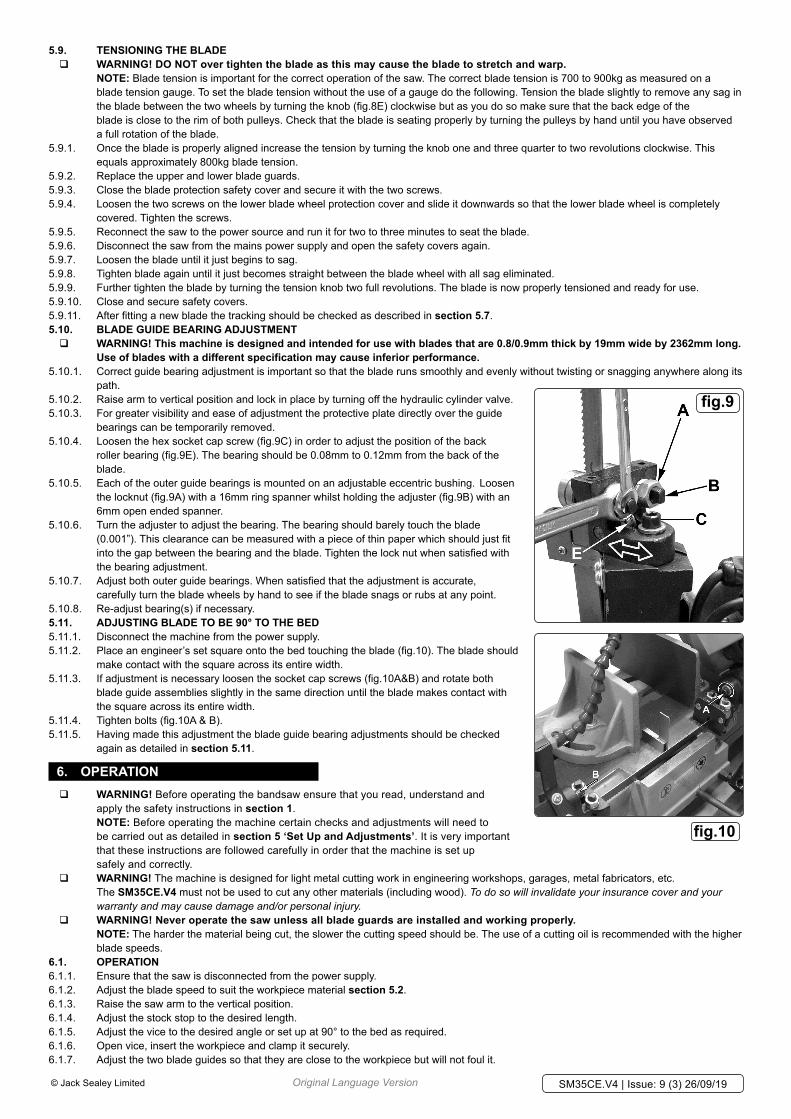
bearings can be temporarily removed.5.10.4. Loosen the hex socket cap screw (fig.9C) in order to adjust the position of the back
roller bearing (fig.9E). The bearing should be 0.08mm to 0.12mm from the back of the blade.
5.10.5. Each of the outer guide bearings is mounted on an adjustable eccentric bushing. Loosen the locknut (fig.9A) with a 16mm ring spanner whilst holding the adjuster (fig.9B) with an 6mm open ended spanner.
5.10.6. Turn the adjuster to adjust the bearing. The bearing should barely touch the blade (0.001”). This clearance can be measured with a piece of thin paper which should just fit into the gap between the bearing and the blade. Tighten the lock nut when satisfied with the bearing adjustment.
5.10.7. Adjust both outer guide bearings. When satisfied that the adjustment is accurate, carefully turn the blade wheels by hand to see if the blade snags or rubs at any point.
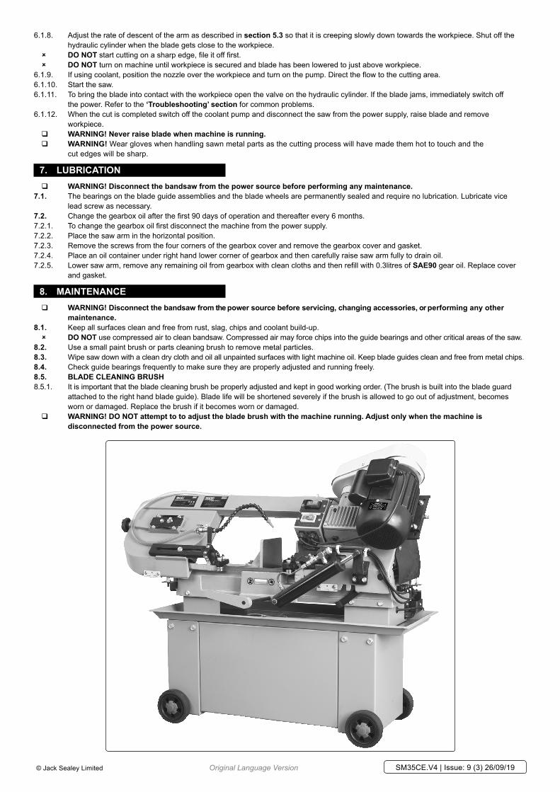
5.10.8. Re-adjust bearing(s) if necessary.5.11. ADjUSTING BLADE TO BE 90° TO THE BED5.11.1. Disconnect the machine from the power supply.5.11.2. Place an engineer’s set square onto the bed touching the blade (fig.10). The blade should
make contact with the square across its entire width.5.11.3. If adjustment is necessary loosen the socket cap screws (fig.10A&B) and rotate both
blade guide assemblies slightly in the same direction until the blade makes contact with the square across its entire width.
5.11.4. Tighten bolts (fig.10A & B).5.11.5. Having made this adjustment the blade guide bearing adjustments should be checked
again as detailed in section 5.11.
6. OPERATION � WARNING! Before operating the bandsaw ensure that you read, understand and
apply the safety instructions in section 1. NOTE: Before operating the machine certain checks and adjustments will need to be carried out as detailed in section 5 ‘Set Up and Adjustments’. It is very important that these instructions are followed carefully in order that the machine is set up safely and correctly.
� WARNING! The machine is designed for light metal cutting work in engineering workshops, garages, metal fabricators, etc. The Sm35CE.V4 must not be used to cut any other materials (including wood). To do so will invalidate your insurance cover and your warranty and may cause damage and/or personal injury.
� WARNING! Never operate the saw unless all blade guards are installed and working properly. NOTE: The harder the material being cut, the slower the cutting speed should be. The use of a cutting oil is recommended with the higher blade speeds.6.1. OPERATION6.1.1. Ensure that the saw is disconnected from the power supply. 6.1.2. Adjust the blade speed to suit the workpiece material section 5.2.6.1.3. Raise the saw arm to the vertical position.6.1.4. Adjust the stock stop to the desired length.6.1.5. Adjust the vice to the desired angle or set up at 90° to the bed as required. 6.1.6. Open vice, insert the workpiece and clamp it securely.6.1.7. Adjust the two blade guides so that they are close to the workpiece but will not foul it.
Original Language Version© Jack Sealey Limited
fig.9
fig.10
SM35CE.V4 | Issue: 9 (3) 26/09/19
6.1.8. Adjust the rate of descent of the arm as described in section 5.3 so that it is creeping slowly down towards the workpiece. Shut off the hydraulic cylinder when the blade gets close to the workpiece.
8 DO NOT start cutting on a sharp edge, file it off first. 8 DO NOT turn on machine until workpiece is secured and blade has been lowered to just above workpiece.
6.1.9. If using coolant, position the nozzle over the workpiece and turn on the pump. Direct the flow to the cutting area. 6.1.10. Start the saw.6.1.11. To bring the blade into contact with the workpiece open the valve on the hydraulic cylinder. If the blade jams, immediately switch off
the power. Refer to the ‘Troubleshooting’ section for common problems.6.1.12. When the cut is completed switch off the coolant pump and disconnect the saw from the power supply, raise blade and remove
workpiece. � WARNING! Never raise blade when machine is running. � WARNING! Wear gloves when handling sawn metal parts as the cutting process will have made them hot to touch and the
cut edges will be sharp.
7. LUBRICATIONn
� WARNING! Disconnect the bandsaw from the power source before performing any maintenance.7.1. The bearings on the blade guide assemblies and the blade wheels are permanently sealed and require no lubrication. Lubricate vice
lead screw as necessary.7.2. Change the gearbox oil after the first 90 days of operation and thereafter every 6 months.7.2.1. To change the gearbox oil first disconnect the machine from the power supply.7.2.2. Place the saw arm in the horizontal position.7.2.3. Remove the screws from the four corners of the gearbox cover and remove the gearbox cover and gasket.7.2.4. Place an oil container under right hand lower corner of gearbox and then carefully raise saw arm fully to drain oil.7.2.5. Lower saw arm, remove any remaining oil from gearbox with clean cloths and then refill with 0.3litres of SAE90 gear oil. Replace cover
and gasket.
8. mAINTENANCE � WARNING! Disconnect the bandsaw from the power source before servicing, changing accessories, or performing any other
maintenance.8.1. Keep all surfaces clean and free from rust, slag, chips and coolant build-up.
8 DO NOT use compressed air to clean bandsaw. Compressed air may force chips into the guide bearings and other critical areas of the saw.8.2. Use a small paint brush or parts cleaning brush to remove metal particles.8.3. Wipe saw down with a clean dry cloth and oil all unpainted surfaces with light machine oil. Keep blade guides clean and free from metal chips.8.4. Check guide bearings frequently to make sure they are properly adjusted and running freely.8.5. BLADE CLEANING BRUSH 8.5.1. It is important that the blade cleaning brush be properly adjusted and kept in good working order. (The brush is built into the blade guard
attached to the right hand blade guide). Blade life will be shortened severely if the brush is allowed to go out of adjustment, becomes worn or damaged. Replace the brush if it becomes worn or damaged.
� WARNING! DO NOT attempt to to adjust the blade brush with the machine running. Adjust only when the machine is disconnected from the power source.
Original Language Version© Jack Sealey Limited SM35CE.V4 | Issue: 9 (3) 26/09/19
Sealey Group, Kempson Way, Suffolk Business Park, Bury St Edmunds, Suffolk. IP32 7AR 01284 757500 01284 703534 [email protected] www.sealey.co.uk
ENVIRONmENT PROTECTIONRecycle unwanted materials instead of disposing of them as waste. All tools, accessories and packaging should be sorted, taken to a recycling centre and disposed of in a manner which is compatible with the environment. When the product becomes completely unserviceable and requires disposal, drain any fluids (if applicable) into approved containers and dispose of the product and fluids according to local regulations.
WEEE REGULATIONSDispose of this product at the end of its working life in compliance with the EU Directive on Waste Electrical and Electronic Equipment (WEEE). When the product is no longer required, it must be disposed of in an environmentally protective way. Contact your local solid waste authority for recycling information.
9. TROUBLESHOOTING
Problem Cause Solution
Excessive blade breakage and/orteeth ripping fromthe blade.
1. Workpiece is loose in the vice.2. Incorrect speed or feed.3. Blade is too coarse.4. Workpiece material is too coarse.5. Incorrect blade tension.6. Blade is in contact with workpiece before saw
is started.7. Blade is rubbing on the wheel flange.8. Blade guides are misaligned.9. Blade is too thick.10. Bad weld on blade
1. Clamp the workpiece securely.2. Check machinist’s handbook.3. Check machinist’s handbook for recommended blade type.4. Use the saw at slower speed and use a smaller tpi blade.5. Adjust blade tension so that it does not slip on the wheel.6. Place blade in contact with the workpiece only after the saw has
started.7. Adjust blade tracking.8. Adjust blade guide alignment.9. Use correct thickness blade.10. Re-weld or replace blade.
Premature blade dulling.
1. Blade tpi is too high.2. Incorrect speed - too fast.3. Inadequate feed pressure.4. Hard spots or scale on the workpiece.5. Blade installed backwards.6. Insufficient blade tension.7. Work hardened material especially stainless
1. Replace with a smaller tpi blade.2. Reduce speed.3. Increase feed pressure by unscrewing tension bar. This will
decrease the spring tension on the arm.4. Reduce speed, increase feed pressure.5. Remove blade, twist inside out and reinstall.6. Increase blade tension.7. Increase feed pressure by reducing spring pressure.
Unusual wear on side or back of blade.
1. Blade guides are worn.2. Blade guides not properly adjusted.3. Blade guide brackets are loose.
1. Replace blade guides.2. Adjust as described in manual.3. Tighten blade guide brackets.
Bad, crooked or rough cuts.
1. Feed pressure too great.2. Blade guide bearings not properly adjusted.3. Inadequate blade tension.4. Blade is dull.5. Incorrect speed.6. Blade guides are spaced out too far.7. Blade guide assembly is loose.8. Blade is too coarse.
1. Reduce feed pressure by increasing the spring tension on the arm.2. Adjust blade guide bearing in accordance with manual.3. Increase blade tension a little at a time.4. Replace the blade.5. Check manual for recommended speed.6. Move guides closer to workpiece.7. Tighten the guide assembly.8. Use a finer blade.
Blade is twisting. 1. Blade is binding in the cut.2. Blade tension is too high.
1. Decrease feed pressure.2. Decrease blade tension.
Original Language Version© Jack Sealey Limited SM35CE.V4 | Issue: 9 (3) 26/09/19
Note: It is our policy to continually improve products and as such we reserve the right to alter data, specifications and component parts without prior notice. Please note that other versions of this product are available. If you require documentation for alternative versions, please email or call our technical team on [email protected] or 01284 757505.Important: No Liability is accepted for incorrect use of this product.Warranty: Guarantee is 12 months from purchase date, proof of which is required for any claim.