Metal ceramics Instructions for use for precious metal...
38
Instructions for use for precious metal ceramic bonding alloys and Edition 05 / 2003 Metal ceramics
Transcript of Metal ceramics Instructions for use for precious metal...

Instructions for use for
precious metal ceramic bonding alloys and
Edi
tion
05/
2003
Metal ceramics

Contents
1. Introduction 21.1 Competence for successful partnership 21.2 Ceramic bonding alloys – proven
for decades 21.3 HeraCeram – the innovative ceramic 31.4 Two ceramics for unlimited possibilities 51.5 Important information 5
2. Instructions for use for theceramic bonding alloys 6
2.1 Waxing up 62.2 Attaching sprues, sprue thickness
and geometry 72.3 Determining the amount of alloy
and reusability 92.4 Preparing the casting ring,
investing, preheating 102.5 Melting and casting 102.6 Cleaning the castings 112.7 Hardening 112.8 Surface conditioning 112.9 Preparing the framework 122.10 Ceramic firing 13
3. Instructions for use forHeraCeram 14
3.1 Applying opaquer 143.2 Dentine incisal layering 163.3 Individual layering using
the Matrix-Set 183.4 Corrections after glaze firing 213.5 Layering of ceramic shoulders 223.6 Final conditioning after
completing the veneer 27
4. Instructions for use with precision attachment techniques 28
4.1 Soldering 284.2 Laser welding 29
5. Firing charts 30
1
Metal ceramics
Metal ceramics
2
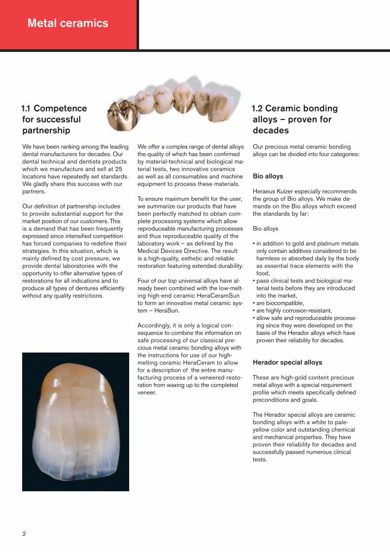
1.2 Ceramic bondingalloys – proven fordecades
Our precious metal ceramic bondingalloys can be divided into four categories:
Bio alloys
Heraeus Kulzer especially recommendsthe group of Bio alloys. We make de-mands on the Bio alloys which exceedthe standards by far:
Bio alloys
• in addition to gold and platinum metalsonly contain additives considered to beharmless or absorbed daily by the bodyas essential trace elements with thefood,
• pass clinical tests and biological ma-terial tests before they are introducedinto the market,
• are biocompatible,• are highly corrosion-resistant,• allow safe and reproduceable process-
ing since they were developed on thebasis of the Herador alloys which haveproven their reliability for decades.
Herador special alloys
These are high-gold content preciousmetal alloys with a special requirementprofile which meets specifically definedpreconditions and goals.
The Herador special alloys are ceramicbonding alloys with a white to pale-yellow color and outstanding chemicaland mechanical properties. They haveproven their reliability for decades andsuccessfully passed numerous clinicaltests.
We offer a complex range of dental alloysthe quality of which has been confirmedby material-technical and biological ma-terial tests, two innovative ceramics as well as all consumables and machineequipment to process these materials.
To ensure maximum benefit for the user,we summarize our products that havebeen perfectly matched to obtain com-plete processing systems which allowreproduceable manufacturing processesand thus reproduceable quality of thelaboratory work – as defined by theMedical Devices Directive. The result is a high-quality, esthetic and reliablerestoration featuring extended durability.
Four of our top universal alloys have al-ready been combined with the low-melt-ing high-end ceramic HeraCeramSunto form an innovative metal ceramic sys-tem – HeraSun.
Accordingly, it is only a logical con-sequence to combine the information onsafe processing of our classical pre-cious metal ceramic bonding alloys withthe instructions for use of our high-melting ceramic HeraCeram to allowfor a description of the entire manu-facturing process of a veneered resto-ration from waxing up to the completedveneer.
1.1 Competence for successful partnership
We have been ranking among the leadingdental manufacturers for decades. Ourdental technical and dentists productswhich we manufacture and sell at 25locations have repeatedly set standards.We gladly share this success with ourpartners.
Our definition of partnership includes to provide substantial support for themarket position of our customers. This is a demand that has been frequentlyexpressed since intensified competitionhas forced companies to redefine theirstrategies. In this situation, which ismainly defined by cost pressure, weprovide dental laboratories with theopportunity to offer alternative types ofrestorations for all indications and toproduce all types of dentures efficientlywithout any quality restrictions.

3
Reduced gold content ceramicbonding alloys and gold castingalloys
Special emphasis is also put on thedevelopment of precious metal dentalalloys according to economic aspects.As far as their chemical-technologicalproperties are concerned, these alloysalmost reach the level of the high goldcontent Herador alloys; yet they are morefavorably priced.
Pd-based alloys of the Albabond group
These alloys possess the advantageouschemical properties which are generallyfound in the group of precious metaldental alloys, however, with regard totheir technological properties and thematerial price they represent a true alter-native to non-precious metal alloys.
Accordingly, HeraCeram can be firedusing the same firing programs in-dependent of the bonding alloy. This wayfiring programs used for a specificbonding alloy will no longer be confused!Time-consuming adapting of firing programs to the respective alloy is nolonger required. If the Heramat Cceramic furnace is used which has beenespecially developed for HeraCeram,the programs have already been pre-stored.
HeraCeram will allow you to save a considerable amount of working timehelping you to increase productivity and reduce costs. The robust firing be-havior ensures reliable, high-quality and reproduceable results.
1. Introduction
1.3 HeraCeram – the innovative ceramic
HeraCeram is suitable for bonding alloysin the CTE range of �25–500°C 13,5 –14,9 µm/mK. Accordingly, a wide rangeof alloys can be selected and used.
With a maximum firing temperature of880 °C HeraCeram offers particularlyreliable processing also for high goldcontent Bio alloys.
HeraCeram is robust, features a wideprocessing tolerance and produces reliable, natural and esthetic resultswith reduced effort.
The firing times of HeraCeram areextremely short.
Time is saved thanks to:
• the high starting temperature (600 °C),• the high rate of heating up (100°C/min),• the low firing temperature
(max. 880°C),• identical firing for all precious metal
ceramic bonding alloys,• the omission of long-term cooling or
a tempering step. Restorations cansimply be removed from the furnace atthe end of the program and cooleddown at room temperature.

4
With HeraCeram you choose the simpleway to natural esthetics
For this purpose fluorescent powderand paste opaque materials in the 16 Vshades are available. 20 HeraCeramstains with different fluorescence levelsallow further individual characterization.
Special matching of colors of the opaque,dentine and incisal materials ensure thatthe color obtained is almost independentof the layer thickness. The opaque mate-rials exhibit excellent coverage at low layer thicknesses (100 µm) and possesscolor-defining characteristics.
Special organic pigments in the materialsallow excellent control of layering. Thehigh stability of the materials during layer-ing simplifies shaping of the restoration.Extremely low firing shrinkage results inhigh dimensional stability. Accordingly,corrections can frequently be avoided.
The perfection of natural esthetics andindividual design of a tooth is achievedwith the Matrix set which leads to reli-able and reproduceable results since itis easy to apply and based on a clearstructure. These instructions for use in-clude processing of the ceramic forstandard layering as well as for the Matrixlayering.
Metal ceramics

1.4 Two ceramics for unlimited possibilities
1.5 Important information:
The following information refers to the procedures, units and materials recommended by Heraeus Kulzer.If products of other manufacturers areused, the corresponding instructions for use and operating instructions mustbe observed.
�Revision mark: This arrow (�) indi-cates all changes and supplements tothe previous version. Furthermore, therelevant text has been printed in italicletters.
�These instructions for use include allthe current information on processing ofour precious metal ceramic bondingalloys. In its previous version “Processinginstructions – Precious metal dentalalloys, Edition11/98” it renders anyinformation concerning the processingof precious metal ceramic bondingalloys obsolete. Previous publicationsreferring to HeraCeram such as “HeraCeram – Instructions for use, Edition 07/2001”, HeraCeram marginmaterials – Instructions for use, Edition08/2001” and the brochure “HeraCeram-Matrix: The discovery of the estheticcode, Edition 03/2001” have become obsolete and are updated in theseinstructions for use.
�All information about the chemicalcomposition, technical data and thepreheating, casting and annealingtemperatures of the alloys can betaken from the package slips or the“Table of technical data of preciousmetal dental alloys”. The information in these instructions are general innature.
5
Two high-end ceramics
When choosing HeraCeramSun andHeraCeram you rely on two high-endceramics with almost identical perfectproperties: superior esthetics andutmost reliability during processing – inparticular in combination with the corresponding Heraeus Kulzer alloys.
HeraCeramSun and HeraCeram:Together they cover the entirerange of metal ceramic techniques.
The small difference is at the same time a considerable benefit: HeraCeramSunis a low-melting ceramic with a process-ing temperature of 790/760 °C and
was especially designed for the HeraSunalloys.
The other ceramic, HeraCeram, is ahigh-melting material with a processingtemperature of 880 °C/860 °C and issuitable for all classical ceramic bondingalloys.
If you use both ceramics, you will coverthe entire range of metal ceramic alloys.
The same veneering technique is usedwith HeraCeramSun as with HeraCeram.This has the following advantages forHeraCeram users:
• The only difference when using HeraCeramSun is the lower firing temperatures.
• The techniques for standard layeringand Matrix layering are identical.
• HeraCeram stains and glazing powderare compatible with both ceramicsystems, so there is no additionaloutlay.
• HeraCeram ceramic liquids are alsocompatible.
HeraCeramSun and HeraCeram may be referred to as “twin sisters” whichfeature the same product and process-ing characteristics at different firing temperatures thanks to our experienceand competence in the field of dentalceramics.
1. Introduction

max. 2 mm
> 2 mm= cracks
nosharpedges
correct incorrect
Metal ceramics
Fig.7, 8: Wax-up with inlay-like reinforcements in the palatal area (top) and with a collar (bottom)
8
7
6
2.1 Waxing up
Crowns and pontics to be veneered withceramic should be waxed up to a re-duced anatomical shape. The thicknessof the wax-up should not be less than0.4 mm so that there is a minimum metal
thickness of 0.3 – 0.35 mm after finishing. Sharp edges, undercuts and deep fis-sures must be avoided when waxing up.Every effort must be made to achievesmooth transition zones.
High gold content palladium-freeceramic bonding alloys:
Sufficiently stable wax-up of the approxi-mal connections must be ensured (crosssection at least 8 mm2). For stability reasons (especially for large span bridges)the palatal side of the pontics should be waxed up with a thin metal collar orat least with an inlay-like interdental reinforcement.
To provide subsequent support duringceramic firing, waxing-up of eyelets tocrowns and pontics is recommended.
9
Fig. 9: Waxed-on eyelets for enhanced support during ceramic firing
0.4mm 0.4mm
correct
incorrect
incorrect
incorrect
Fig.1: Correct wall thickness when waxing up
Fig. 2: Top view of correct and incorrect wax-up
1
2
Fig. 3: Lateral view of correct and incorrect wax-up
Fig. 4: Wax-up of the interdental connections
Fig. 5: Wax-up of the pontics Fig. 6: Wax-up of the shoulderless preparation
correct incorrect incorrect
6
5
correct
3
4

The distance of the castings to the cast-ing ring wall should always be the sameto ensure uniform cooling conditions(min. 5 mm).
The bar sprues must be exactly in thethermal center, i.e. the distance betweenthe bar and the bottom of the castingrings should be 27.5 mm. Positioning ofthe sprue system in the casting ring can be easily checked using the Heraeusspruing aid (see Fig.16).
Implant suprastructures:
With implant suprastructures a sufficientlythick layer of wax (min.0.3 mm) shouldbe applied on the prefabricated preciousmetal copings to avoid the formation offissures and cracks in the ceramic sincethe precious metal copings have a verylow CTE.
We expressly point out that the recom-mendations of the implant manufacturershave to be observed.
Wax-up and indication range of the alloy
�When planning the span of bridges,the information about the type and the strength of the alloy to be usedmust be considered.
7
All dimensions in mm
.
.
11
2. Instructions for use for the ceramic bonding alloys
2.2 Attaching sprues,sprue thickness andgeometry
Attaching sprues for bar casting
For bridge work we recommend the barcasting technique. Feeder sprues with alength of 2.5–5 mm and a Ø of 3.5 mmare attached at an angle of 45° to thepalatal or lingual side of the wax object.Each pontic must be connected with afeeder sprue; for larger molar crownsthe connection of two sprues is required.The feeder sprues are connected by ahorizontal bar with a Ø of 5 mm.
The bar connects to the sprues andruns parallel to the casting. The spruescoming from the cone former are con-nected to the bar between the first andsecond third resp. between the secondand third third of the bar. These sprueshave the same diameter as the bar.
Fig.10: Pattern of ideal casting mould design
Abb.11: Schematic view of bar castingDimensions for ceramic bonding alloys
castings
Bar sprue
d-1.
5
.Spruing
10
The feeder sprues must always be attached to the thickest parts of the wax-up.
d = diameter of the sprue in mmd = for ceramic bonding alloys 4.5 – 5.0 mml = Length of the spruing

Metal ceramics
Casting voluminous elements
�How can voluminous castings be cast without any blowholes?
Figures 13 and 14 illustrate the differ-ences between a conventional “normal” sprue system which is usedfor all pontics and the type of spruesystem required for “extreme” pontics
(or voluminous elements) with thick-nesses of more than 10–12 mm. The spruing for voluminous elementsshown here may only be used when casting voluminous elements.
8
Fig.12: Correct and incorrect position of severalbridges in the casting ring correct
Fig.13: Ø 5.0 mm, sprue bar Ø 3.5 mm, feeder sprues
Standard sprue system: In the case of ce-ramic bonding alloys with pontic constructionssprues featuring a horizontal bar with a diam-eter of 5.0 mm and a connector between the bar to the object (diameter 3.5 mm and length 2.5–5.0 mm) are attached. The connector(bar) is placed in the center of the casting ring.
Fig.14: Ø 5.0 mm, connectorØ 3.5 mm, feeder spruesØ 5.0 mm with reinforcements for voluminous elements
Sprue system for extremely voluminous elements: The thickness of 5.0 mm for the hori-zontal bar and 3.5 mm for the feeder spruesremain unchanged. The distance between thehorizontal bar and the object is increased to10.0 mm. Additionally, the bases of the spruesat the horizontal bar are increased to 5.0 mm
(see drawing). The position of the horizontal barremains in the center of the casting ring. Thischange allows to achieve directional solidifi-cation owing to the large melting quantity of thecasting and the inherent shift of the thermalcenter.
If two or three bridge patterns are placedon a cone former, it must be ensuredthat they are placed in a circle equidistantto the wall of the casting ring.
55.0 mm
5.0 mm Distance to the bottom
27.5 mm27.5 mm
10.0
mm
3.5 mm
5.0 mm
5.0 mm
2.5–5.0
mm
5.0 mm
3.5 mm
14
12
13
incorrect

The mixing ratio is a maximum of 2/3 of old material to at least 1/3 of new material.
Attaching sprues for single units
Direct spruing can also be used for singlecrowns, inlays and onlays. The sprueshould be attached to the wax patternwithout tapering. The Ø of the spruesfor direct spruing should be 4 mm. Whendetermining the thickness of the sprues,
the volume of the casting pattern andthe casting temperature of the alloyshould be taken into account. Thickersprues are required for alloys with ahigher melting temperature and volumi-nous casting patterns.
The required alloy quantity is obtained by multiplying the weight of the wax pattern with the density of the alloy, divided by the density of the wax (average 0.93 g/cm3).
9
4
55
=
=
All dimensions in mm
min5
min5
15
Fig.15: Schematic view of spruing for singleunits. Dimensions when used for ceramicveneering.
Prior to waxing up the casting patternonto the sprue former the required alloyquantity must be calculated. The waxpattern and the attached sprues areweighed.
There is no need to add any extra alloyfor the casting button if the alloy is to becast using the vacuum pressure castingtechnique.
Any sprues left over can be carefullycleaned and reused after adding newalloy. They are cleaned by sandblastingthem with aluminium oxide and thenrinsed under running water and dried.
2.3 Determining theamount of alloy and reusability of casting buttons
2. Instructions for use for the ceramic bonding alloys

Metal ceramics
2.5 Melting and casting
Graphite crucibles
High gold content ceramic bonding alloysand the reduced gold content, silver-containing alloys can be melted in graph-ite crucibles resp. – if induction castingmachines are used – in ceramic crucibleswith graphite insert.
Melting should preferably be carried out in Heraeus Kulzer graphite crucibles.These crucibles are free from any addi-tives that damage the alloy and featurea long service life.
Ceramic crucibles
All reduced gold content ceramic bond-ing and palladium-based alloys must be melted in ceramic crucibles by usingmelting powder. The reason for that isthe tendency of alloys with a high pal-ladium content to absorb carbon duringmelting which results in a deterioration of the mechanical properties and the for-mation of bubbles during ceramic veneer-ing. That is why these alloys should notcome into contact with carbon duringmelting and casting.
Suitable Heraeus Kulzer ceramic cru-cibles are available for all Combilaborcasting machines. To melt the individualalloys, separate ceramic melting cru-cibles must be used.
�The recommendation for the suitablecrucible material is stated on the alloypacket.
Suitable casting machines and melting methods
We recommend to melt and cast in the temperature-controlled, resistance-heated vacuum pressure casting ma-chines CL-G 97, CL-G 94 or the induc-tion-heated vacuum pressure castingmachines Heracast iQ, CL-I 95 and CL-IG made by Heraeus Kulzer.
�The casting temperature and the pre-heating temperature of the casting ringare stated on the alloy packet.
As a guideline: casting temperature = liquidus temperature +150 °C.
Do not quench the casting ring inwater after casting.
10
2.4 Preparing the casting ring, investing,preheatingWaxing onto the sprue former
The completed wax patterns should onlybe placed on sprue formers which arecompatible with the casting machine tobe used.
�The wax pattern is attached so that thehorizontal bar lies vertical and has adistance of 27.5 mm to the base of thecasting ring. The horizontal bar, how-ever, must never be taken through thecenter of the casting ring to avoid differ-ent cooling conditions in the castingpattern which will result in the formationof blowholes (see also Fig.12, page 8).The horizontal bar must rather be shiftedto the outside to ensure directionalsolidification and to avoid casting errors(blowholes) (see also Fig.11, page 7).
Ensure the wax junction is smooth whenwaxing the sprues onto the sprue former.
Suitable investment materials
We recommend the use of phosphate-bonded investment materials from Heraeus Kulzer for all precious metal dental alloys.
Fig.16: Correct positioning of thehorizontal bar using the Heraeus spruing aid
16
�Please observe the processing in-structions enclosed to the respectiveinvestment material.
�Palladium-containing ceramic bondingalloys which can only be melted inthe ceramic crucible because of therisk of carbon absorption (see infor-mation on the packet) must not becast in graphite-containing, phosphate-bonded investment materials either.

Har
dnes
s (H
V)
Time (min)
11
2.6 Cleaning the castings
Mechanical removal of the investment materials
�If casting rings are used, the mouldsare first pressed out of the casting ringafter cooling down to room temperatureand the investment is carefully removedfrom the casting with plaster nippers.
Sandblasting
Investment material residues are removedby sandblasting with 50 µm aluminiumoxide.
In particular the soft, high gold contentpalladium-free alloys should only be sand-blasted at a maximum pressure of 2 bar.
Fig.18 a: Suitable finish-ing tools for most ceramicbonding alloys
Fig.18b: Suitable finish-ing tools for high-goldcontent ceramic bondingalloys
Fig.19: Finished crowns
18a
Do not devest castings with a hammer because of the risk of deformation!
18b
Diamond-coated finishing tools must not be used.
19
2.8 Surface treatment
The sprues are cut off and the frame-works are finished using fine-cut tungsten carbide cutters.
The best basis for an optimal metal-ceramic bond is achieved by preparingwith diamond-cut tungsten carbide cutters with a chamfer.
Suitable ceramic-bonded stones canalso be used.
Due to the risk of formation of bubblesduring ceramic firing the contact with carbon and carbon-containing substances must be avoided.
2.7 Hardening
Hardening after casting
Most alloys harden automatically by slowcooling in the casting ring. Almost allalloys can also be hardened by additionalheat treatment.
�The annealing parameters and the hard-ness and strength values that can beachieved are stated on the alloy packet.
2. Instructions for use for the ceramic bonding alloys
The information provided by the manufacturers must be observed.
Fig.17: Annealing behavior of precious metaldental alloys
Metal ceramics
12
21b
23
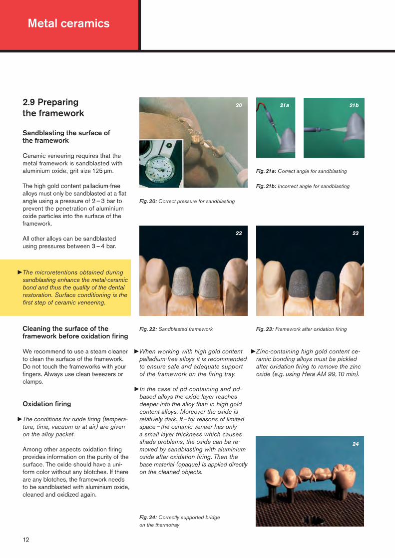
Fig. 22: Sandblasted framework Fig. 23: Framework after oxidation firing
Fig. 21a: Correct angle for sandblasting
Fig. 21b: Incorrect angle for sandblasting
21a
22
20
Fig. 20: Correct pressure for sandblasting
Fig. 24: Correctly supported bridge on the thermotray
�When working with high gold contentpalladium-free alloys it is recommendedto ensure safe and adequate supportof the framework on the firing tray.
�In the case of pd-containing and pd-based alloys the oxide layer reachesdeeper into the alloy than in high goldcontent alloys. Moreover the oxide isrelatively dark. If – for reasons of limitedspace– the ceramic veneer has only a small layer thickness which causesshade problems, the oxide can be re-moved by sandblasting with aluminiumoxide after oxidation firing. Then thebase material (opaque) is applied directlyon the cleaned objects.
�Zinc-containing high gold content ce-ramic bonding alloys must be pickledafter oxidation firing to remove the zincoxide (e.g. using Hera AM 99,10 min).
2.9 Preparing the framework
Sandblasting the surface of the framework
Ceramic veneering requires that themetal framework is sandblasted withaluminium oxide, grit size 125 µm.
The high gold content palladium-freealloys must only be sandblasted at a flatangle using a pressure of 2 – 3 bar toprevent the penetration of aluminiumoxide particles into the surface of theframework.
All other alloys can be sandblastedusing pressures between 3 – 4 bar.
Cleaning the surface of theframework before oxidation firing
We recommend to use a steam cleanerto clean the surface of the framework.Do not touch the frameworks with yourfingers. Always use clean tweezers orclamps.
Oxidation firing
�The conditions for oxide firing (tempera-ture, time, vacuum or at air) are givenon the alloy packet.
Among other aspects oxidation firingprovides information on the purity of thesurface. The oxide should have a uni-form color without any blotches. If thereare any blotches, the framework needsto be sandblasted with aluminium oxide,cleaned and oxidized again.
�The microretentions obtained duringsandblasting enhance the metal-ceramicbond and thus the quality of the dentalrestoration. Surface conditioning is thefirst step of ceramic veneering.
24

Cooling after ceramic firing
�Matching the coefficients of thermalexpansion of the alloy and the ceramicsby means of long-term cooling is nolonger required when veneering withHeraCeram. Rapid cooling down isdescribed in chapter 3.1.
If other ceramics are used, it is possiblethat the coefficients of thermal expansionand the resulting thermal expansioncurves of alloy and ceramic only matchto a certain degree. This may causetensions in the metal/ceram bond aftercooling down which result in the formation of cracks in the ceramic.
But adequate cooling speeds after firingcan lead to balancing the thermal ex-pansion curves of both materials. Aftercooling, the optimum final condition iswhen the ceramic is exposed to minorcompressive stress. The cooling speedshave been determined for every ceramicbonding alloy and have been tested forseveral years in practice. Relevant dataand information can be found in the“Table of technical data of precious metaldental alloys”.
Definition of the cooling rates fordentine firing and subsequent firingprocesses:
Normal cooling down (n)The firing platform is driven down at theend of the program and the firing traywith the objects is removed after 2 – 3minutes.
Slow cooling down (l)�Conditions vary depending on the type
of furnace. Programs are e.g.: Whenthe objects are driven down, a hold of3 – 5 minutes at 800 °C is required orafter the end of the program objects arecooled down slowly for 5–6 minutesuntil the initial temperature is reached. Please observe the operating instructionsof the furnace and the instructions foruse of the ceramic.
�Rapid cooling down (s)At the end of the program the firingtable is driven down immediately. Thefiring tray with the objects can beremoved immediately and is cooled at room temperature.
13
Cleaning the framework surfacebefore ceramic firing
We recommend to use a steam cleanerfor cleaning the surface of the frame-work. Do not touch the framework withyour fingers after cleaning. Always useclean tweezers or clamps. After steamcleaning, the dry frameworks are readyfor ceramic veneering.
2.10 Ceramic firing
�Temperatures and conditions of the ce-ramic firing processes for HeraCeramcan be found in the firing charts (page30 – 34).
�Refer to the instructions of the respec-tive manufacturer when firing otherceramics.
Firing of high gold content palladium-freealloys: Safe and adequate support on the firing tray is generally recommended.
Ceramic firing after primary soldering:Surfaces to be veneered must not bewetted with solder across larger areas.
2. Instructions for use for the ceramic bonding alloys
�Veneering with HeraCeramThe working steps for layering the ceramic and final treatment of the alloys are included in chapter 3: Instructions for use for HeraCeram.
�Soldering and laser weldingThe working steps for carrying outsoldering and laser welding areincluded in chapter 4 “Precisionattachment techniques” of theseinstructions for use.

Metal ceramics
14
3.1 Applying opaque
Only for veneering non-preciousmetal alloys:
Pre-Opaque
HeraCeram Pre-Opaque supports pro-cessing of HeraCeram on non-preciousmetal ceramic bonding alloys (NPM). If Pre-Opaque is used, NPM-specificcooling is no longer mandatory!
Processing:After finishing and sandblasting the athin layer of the ready-to-use paste isapplied on to the veneer surface of themetal framework using the paste opaquebrush and fired under vacuum (!) withthe recommended oxide firing programof the respective NPM alloy.If oxide firing is not recommended, thePre-Opaque ceramic is fired with theopaque firing program at 980 °C and a hold of 10 min under vacuum.
P1 P2
P3
A1 A2 A3 A3,5
Powder opaque OA1 OA2 OA3 OA3,5
Paste opaque POA1 POA2 POA3 POA3,5
Dentinee DA1 DA2 DA3 DA3,5
Incisal S1 S1 S2 S2
Mamelon,Secondarydentinee MD1 MD1 SD2 SD2
Value VL1 VL2 VL3 VL4
Opal incisal OS1 OS1 OS2 OS2
Shoulder ma-terials HM / LM 1 1 2 2
Fig. P1: Applying the Pre-Opaque in a thin layer
Fig. P2: Thin and relatively uniform applicationof the Pre-Opaque before firing
Fig. P3: After firing, the Pre-Opaque exhibits a slight silky luster
Note: If Pre-Opaque is not used, werecommend a firing temperature of 950 °C for the first opaque firingwhen processing NPM alloys.
Note: During firing, some NPM alloysmay form water soluble oxides whichmay cause yellowish discoloration in theceramic. To avoid such discoloration,NPM frameworks should be rinsed offshortly with water after firing.
Paste opaque
The paste opaque is supplied in a ready-to-use consistency. The viscosity andthe enclosed paste opaque brusheshave been matched perfectly. The pasteopaque is applied in two thin layers andfired.
The firing temperature for the pasteopaque is also 880 °C, however thepredrying phase must be adapted to the drying behavior of the paste liquid(see firing charts on page 30–34).
If the paste opaque has become drierand thus firmer due to extended storage,the ideal consistency can be reachievedby careful adding paste opaque liquid.
6 intensive opaque materials are availablefor individualization of the opaque layer. After firing, the opaque layer reveals alustrous surface.
The ceramic firing tables can be found on page 30–34 of these instructions for use.
Cooling down after ceramic firing
At the end of the program the firingtable is driven down immediately. The firing tray with the objects can beremoved immediately and is cooled at room temperature.

15
1 Powder opaque
The powder opaque is mixed with thepowder opaque liquid to obtain a varnish-like consistency and applied uniformly covering the entire surface to be veneered. It can be applied withceramic brushes or ball-end instru-ments (e.g. made of glass) dependingon the technique used.
Firing temperature 880 °C.
The opaque layer is silky matt after firing.
If a second layer is required, it is appliedin the same way and fired at the sametemperature.
There are 6 intensive opaque materialsfor individualization of the opaque layer:
Bleach, a whitish opaque for very lighttooth shades resp. for whitening theopaque shades.
Gold, for a warmer hue owing to in-creased chroma from the depth of theveneer.
Gingiva, pink-colored opaque for areasin which the Gingiva materials are used.
OCA; OCB; OCC, opaques with intensi-fied chroma for A, B and C shades, e.g.for characterization in the cervical area.
Approx.10% mamelon or secondarydentine shades are added when mixingthe dentine ceramics.
OT1 – OT10; OTY; OTB; OTA; OTG andOT Ice can each be used individuallywith any of the shades.
1a
32
Fig.1: Uniform application of the paste opaque Fig.1a: …or powder opaque
A4 B1 B2 B3 B4 C1 C2 C3 C4 D2 D3 D4
OA4 OB1 OB2 OB3 OB4 OC1 OC2 OC3 OC4 OD2 OD3 OD4
POA4 POB1 POB2 POB3 POB4 POC1 POC2 POC3 POC4 POD2 POD3 POD4
DA4 DB1 DB2 DB3 DB4 DC1 DC2 DC3 DC4 DD2 DD3 DD4
S4 S1 S1 S2 S4 S1 S3 S3 S3 S1 S2 S2
SD2 MD2 MD2 MD3 MD3 MD2 SD1 SD2 SD2 MD1 MD3 SD1
VL4 VL1 VL2 VL3 VL4 VL1 VL2 VL3 VL4 VL2 VL3 VL4
OS4 OS1 OS1 OS2 OS4 OS1 OS3 OS3 OS3 OS1 OS2 OS2
6 3 3 4 4 5 5 6 6 1 2 4
Shade classification of HeraCeram ceramics
Fig. 3: Characterization of the opaque layerwith intensive opaque (e.g. OCA)
Fig. 2: Silky matt surface of the opaque layerafter firing
3. Instructions for use for HeraCeram
Metal ceramics
Note: A safety mask should be wornand a dust extractor used whengrinding ceramics. Avoid inhalingthe ceramic dust.
16
65
7 8
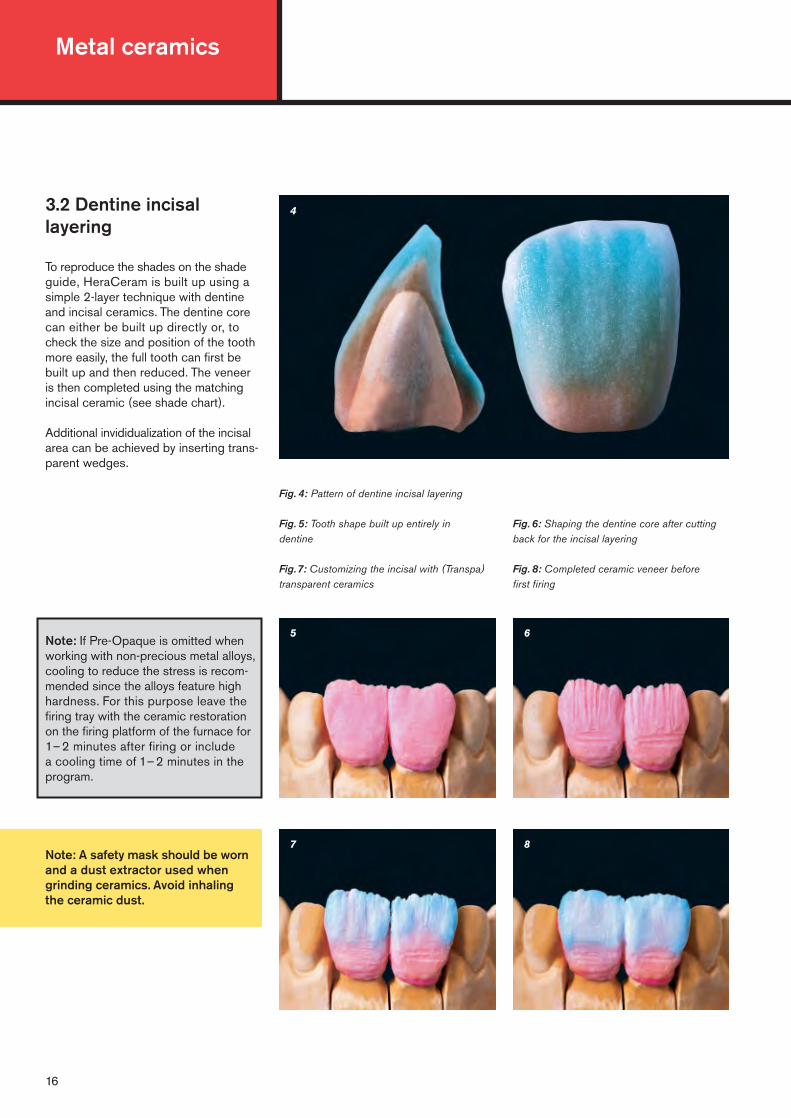
3.2 Dentine incisal layering
To reproduce the shades on the shadeguide, HeraCeram is built up using asimple 2-layer technique with dentineand incisal ceramics. The dentine corecan either be built up directly or, tocheck the size and position of the toothmore easily, the full tooth can first bebuilt up and then reduced. The veneer is then completed using the matchingincisal ceramic (see shade chart).
Additional invididualization of the incisalarea can be achieved by inserting trans-parent wedges.
Fig. 4: Pattern of dentine incisal layering
Fig. 5: Tooth shape built up entirely in dentine
Fig.7: Customizing the incisal with (Transpa)transparent ceramics
Fig. 6: Shaping the dentine core after cuttingback for the incisal layering
Fig. 8: Completed ceramic veneer before first firing
4
Note: If Pre-Opaque is omitted whenworking with non-precious metal alloys,cooling to reduce the stress is recom-mended since the alloys feature highhardness. For this purpose leave thefiring tray with the ceramic restorationon the firing platform of the furnace for1–2 minutes after firing or include a cooling time of 1–2 minutes in theprogram.

17
9 10
11
Corrective layering
After the ceramic firing, the surface ofthe veneer has a glazed texture. Theapproximal and occlusal contact pointsare adjusted by grinding in with rotarydiamond tools. A layer of dentine, incisalor transparent ceramic is added to com-pensate for the firing shrinkage and firedusing the dentine-2 firing program.
Glaze firing
If corrective firing of the ceramic is notrequired, the veneer is prepared usingdiamond tools, i.e. contours and surfacetexture are shaped. Any grinding dustand dirt are removed from the ceramicsurface, e.g. with a steam cleaner. Finally,the veneer can also be characterizedindividually using glazing liquid and stains.
�Since the refractive index of HeraCeramstain liquid is similar to that of the ce-ramic, layering and shade become visiblewhen the surface is coated with stainliquid. This enables the characterizationwith glazing liquid and stains to beeasily checked.
Firing temperature: 850 °C
�Depending on the desired degree ofluster, the holding time can be extendedor reduced or the temperature can belowered.
12
13 14
14aFig. 9: HeraCeram after the first firing
Fig.10: Fine adjustment of the tooth contour
Fig.11: Finishing the contours and surface texture
Fig.12: Ceramic surface coated with HeraCeram stain liquid
Fig.13: Final individualization with HeraCeram stains
Fig.14, 14 a: After glaze firing
3. Instructions for use for HeraCeram

Metal ceramics
Note: Individual layering is alwaysbased on the respective patient.Accordingly, the following layeringis only an example. The practicaluse of the individual Matrix ceramicsmay vary from case to case andmust be decided individually.
Matching of the Matrix materials(classification) can be found onpage 20.
18
Fig.15: Sagittal section of a Matrix layering
Fig.17: The crowns are completely built up indentine to allow cutting back in a controlledmanner
Fig.18: The cut back is carefully smoothedwith a brush
16 17
18 19
15
Fig.16: Mamelon or secondary dentine mixedwith the dentine of the respective shade in-creases the richness of shade (chroma) in thecervical area
Fig.19: The value ceramics are layered slightlymore thickly towards the incisal and graduallythin out towards the body of the tooth. The valueceramics regulate the lightness of the layering incorrect relation to the core shade
3.3 Individual layeringusing the Matrix-Set
according to Paul A. Fiechter,Master Dental Technician
When individualizing a layering, priority is given to reproducing the shade andshade nuances of the patient’s toothwith all the optical light elements such as lightness, transparency, fluorescenceand opalescence.
The Matrix Set not only provides ceramicswith exceptional esthetic properties, italso offers a concept of esthetics thatproduces natural results with minimumlayering effort. This concept is easy toapply since it is based on a clear structure.
The appropriate dentine powder is mixedwith approx.10% mamelon or secondaryMD or SD dentine ceramics to emphasizethe cervical area. These ceramics in-tensify the luminosity of the shades bybalancing the chroma and fluorescence.
After fully building up the anatomicalshape with dentine ceramics, the layer-ing is reduced to the dentine core by cutting it back in a controlled manner.
Hera eram
DA2Dentin
Dentine
Hera eram
DA2Dentin
Dentine
Hera eram
DA2Dentin
Dentine
Hera eram
MD2Mamelon Dentin
Mamelon Dentine
Hera eram
VL2Value

19
24
2322
20 21
Fig. 20: Smooth transitions ensure there is no junction line with the core shade
Fig. 21: The mamelon and dentine ceramicsmerge with the value ceramics . . .
Fig. 24: The anatomical shape is completedusing a matching opal incisal or various opaltransparent ceramics
Fig. 23: A band of Opaltranspa (opal trans-parent) Ice is applied over the mamelons
Fig. 22: . . . and are contoured with a brush toresemble mamelons. The result is an impressiveinterplay between lighter and darker shadedareas. This creates mamelons that are also illu-minated by the highly fluorescent value ce-ramics from the depth of the layering
To regulate the lightness or for partialwhitening of the dentine, the valueceramics are layered slightly morethickly in the incisal area and graduallythin out towards the body of the tooth.Smooth transitions prevent a junctionline at the core shade.
Mamelon and dentine merge into thevalue ceramics and can be contouredusing a brush. This creates a naturalinterplay between lighter and darkershaded areas. The mamelon structuresare emphasized since they are “illumi-nated” by the more fluorescent valueceramics from the depth of the built-up.
A band of Opaltranspa (opal transpar-ent) Yellow emphasizes the halo effect.
The anatomical shape is completed withthe matching opal incisal and/or opaltransparent ceramics.
See dentine firing for firing cycle (firing temperature 860 °C)
Firing shrinkage is compensated forafter firing and fine adjustments aremade to the shape and layering.
Finally, HeraCeram stains and glaze(glazing liquid) can be used forcharacterization.
Hera eram
VL2Value
Hera eram
MD2Mamelon Dentin
Mamelon Dentine
Hera eram
MD2Mamelon Dentin
Mamelon Dentine
Hera eram
OS2OpalschneideOpal Incisal
Hera eram
OTYOpalschneideOpal Incisal
Hera eram
OTIceOpal Transpa
3. Instructions for use for HeraCeram

Metal ceramics
20
MD mamelon dentine; SD secondary dentine –Ceramics for creating natural luminosityin mamelons by balancing the croma andfluorescence.
VL value ceramics –Highly fluorescent ceramics for adjust-ing lightness in correlation to the chromaof the individual shade level (A1; A2; A3)with the 3-layer technique.
OS opal incisals –These incisal ceramics replace the corresponding standard incisal ceramics.They are classified and applied in thesame way.
Description of the Matrix components
The degree of glaze and texture ofthe ceramic surface can be regu-lated by the glaze firing using thetemperature and holding time atfinal temperature. Other influencingfactors are the surface preparationand preparation for glaze firing.Therefore the directions for glazefiring can only be used as a roughguide and should be amended toachieve the desired result.
See glaze firing for firing cycle (firing temperature 850 °C)
HeraCeram can also be polishedmechanically. Our HP paste is perfectlysuitable for final polishing.
25
Fig. 25: Completed veneer after glaze firing

21
OT (Opaltranspa)opal transparent ceramics –Transparent ceramics for individual layer-ing reflect the spectrum of natural toothenamel.
OT1–OT10: neutral opalescenceincreases in intensity and decreases in transparency from OT1 to OT10. OT1 is the most transparent of the opalceramics. OT10 is whitish-opal.
OTY; OTB; OTA; OTG and OT Ice: modified shades of opal transparentceramicsOT Yellow yellowishOT Blue bluishOT Amber reddishOT Grey greyishOT Ice light bluish
Preciano Electroforming
In this context we would like to draw your attention to the Precianoelectroforming system by HeraeusKulzer since the working steps de-scribed for veneering with HeraCeramare identical with the ones for pre-cious metal ceramic bonding alloys.
The use of Preciano allows to producethin high-precision crown copingsmade of fine gold. This technique isparticularly suitable above all in thearea of anterior teeth if there is onlylimited space available. The fabri-cation of these crown copings andthe preparation for ceramic veneeringare described in separate instructionsfor use.
3. Instructions for use for HeraCeram
3.4 Corrections afterglaze firing
The correction material with a firing temperature of 810 °C provides a sufficient temperature difference for corrections after glaze firing, e.g. optimizing contact points. Completedveneers are no longer impaired by these corrections.
The correction material is colorless and transparent. It can be mixedwith any of the HeraCeram ceramics to adjust the shade.
Note! The firing resp. processingtemperature of the correction material increases depending on the mixing ratio (e.g. with a ratio of 1:1 the firing temperature should be approx. 835 °C).

Metal ceramics
22
3.5 Layering of ceramicshoulders
The HM (high fusing margin) shoulderceramics are applied in the usual wayand fired at a temperature of 870 °C.
The LM (low fusing margin) shouldermaterials are only used after the veneerhas been completed (i.e. after glaze firing). Due to the low firing temperatureof 790°C LM shoulder ceramics canalso be used as a correction material,e.g. for adjusting the contour, pontics or adding contact points.
HM and LM shoulder ceramics are contained in the Shoulder Ceramic Set.
HM/LM 1–6 are combined with eachtooth shade according to the shadechart. HM/LM 7 is also referred to asbleach. It is an opaque white shoulderceramic with increased fluorescenceand can be used for masking dark areas(discolored tooth substance) resp. foradjusting lightness and transparency ofHM or LM ceramics.
Preparation requirements
The tooth should be prepared with ashoulder or at least a well-defined deepchamfer for fabricating metal-free crownmargins.
Fig. 26: Shade combinations of individualshoulder ceramics with other ceramics
Fig. 28: Labial view of model dies with shoulder and deep chamfer preparations
Fig. 27: Correct and incorrect contouring of the shoulder preparation
Fig. 29: Lateral view of model dies with shoulder and deep chamfer preparations
correct
Shoulder preparation
Deep chamferpreparation
Shoulderlesspreparation
correct incorrect
27
2928
26
HM
LM
1 2 3 4 5 6 7A
1; A
2; D
2
A3;
A3,
5; D
3
B1;
B2
B3;
B4;
D4
C1;
C2
A4;
C3;
C4
Ble
ach
23
30 31
32
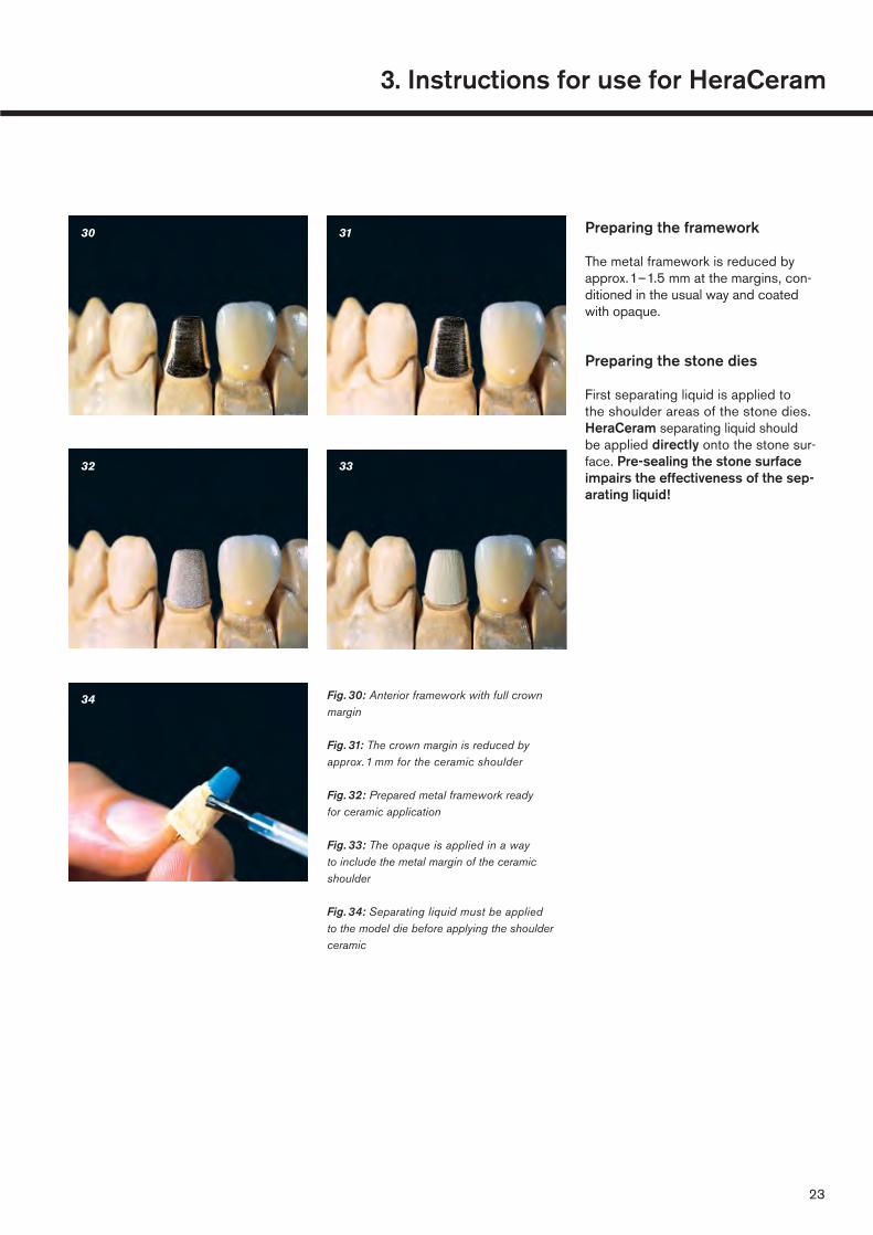
Fig. 30: Anterior framework with full crownmargin
Fig. 31: The crown margin is reduced byapprox.1 mm for the ceramic shoulder
Fig. 32: Prepared metal framework ready for ceramic application
Fig. 33: The opaque is applied in a way to include the metal margin of the ceramicshoulder
Fig. 34: Separating liquid must be appliedto the model die before applying the shoulderceramic
Preparing the framework
The metal framework is reduced byapprox.1–1.5 mm at the margins, con-ditioned in the usual way and coatedwith opaque.
Preparing the stone dies
First separating liquid is applied to the shoulder areas of the stone dies.HeraCeram separating liquid should be applied directly onto the stone sur-face. Pre-sealing the stone surfaceimpairs the effectiveness of the sep-arating liquid!
34
33
3. Instructions for use for HeraCeram

Metal ceramics
Carefully drying with a hairdryer adds more strength to the shouldermaterial and improves its handlingcharacteristics.
See page 30–34 for the firingcycle.
First layering with HM shoulder ceramic
The shoulder ceramic is mixed with SMliquid to obtain a sculptable dough andapplied to the cervical area of the crown.Excess liquid is removed by slightlycondensing it. After contouring andsmoothing the ceramic surface, thecrown can be removed from the modeland fired.
Fig. 35: Shoulder ceramic is applied to the exposed area of the preparation and the cervical area of the crown
Fig. 36: Completed ceramic shoulder build-up with HM ceramic
35 36
24
25
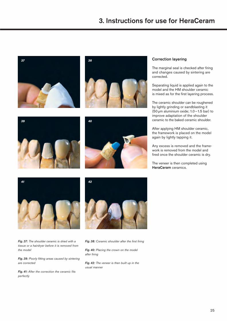
Correction layering
The marginal seal is checked after firingand changes caused by sintering arecorrected.
Separating liquid is applied again to themodel and the HM shoulder ceramic is mixed as for the first layering process.
The ceramic shoulder can be roughenedby lightly grinding or sandblasting it (50 µm aluminium oxide; 1.0–1.5 bar) toimprove adaptation of the shoulderceramic to the baked ceramic shoulder.
After applying HM shoulder ceramic,the framework is placed on the modelagain by lightly tapping it.
Any excess is removed and the frame-work is removed from the model andfired once the shoulder ceramic is dry.
The veneer is then completed usingHeraCeram ceramics.
38
4039
37
Fig. 37: The shoulder ceramic is dried with atissue or a hairdryer before it is removed fromthe model
Fig. 39: Poorly fitting areas caused by sinteringare corrected
Fig. 41: After the correction the ceramic fitsperfectly
Fig. 38: Ceramic shoulder after the first firing
Fig. 40: Placing the crown on the model after firing
Fig. 42: The veneer is then built up in the usual manner
4241
3. Instructions for use for HeraCeram

Metal ceramics
26
4645
LM (low fusing) shoulder ceramic
LM shoulder ceramics are used to fabricate ceramic shoulders after theveneer has been completed, i.e. afterglaze firing.
The procedure is the same as that usedfor HM shoulder ceramics, however, thelow firing temperature of 790°C must beobserved.
LM ceramics can be used not only for fabricating and correcting ceramicshoulders but also for any other type of corrections, e.g. corrections of con-tours or adding contact points.
Fig. 43: Completed ceramic-faced crowns withceramic shoulder
Fig. 45: Correcting the marginal fit with LM shoulder ceramic
Fig. 44: Ceramic-faced crown with a poor marginal seal
Fig. 46: Ceramic-faced crown after correctionlayering
4443

27
3.6 Final conditioningafter completing theveneer
Polishing the ceramic
HeraCeram can be easily polishedmechanically. Our HP paste has provedto be perfectly suitable for final polishing.
Polishing the metal surface
The hardness of the alloy should betaken into consideration when polishingto obtain a smooth shiny surface. Thedirection of the polishing heads shouldbe continually changed during polishing.Only a small quantity of polishing agentis required when polishing to high lusterwith a rotary linen, cotton or wool buff.The restoration should be cleaned beforeany change of polishing agent. Clean-ing is not required before changing thepolishing head if the same polishingagent is being used.
Soft alloys are prepolished with a rubberpolisher until the polished surfaces arefree from streaks and striae. Then polish-ing is continued using a hard brush inthe handpiece at low speed (5000 rpm)and a small quantity of Hera GPP 99gold polishing paste and little pressure.High luster polishing is carried out with a soft goathair brush in the handpieceand Hera GPP gold polishing paste 99at low speed (5000 rpm) and little pres-sure. Then the excess paste is removedusing wool buffs.
Pickling the crown margins of completed restorations
Residual oxide on the margins of veneer-ed crowns can cause gingival irritation.To improve patient safety, we recommendalways pickling completed restorations to remove any residual oxide. For thispurpose the restoration is pickled inHera AM 99 for approx.10 minutes at70°C. (The solution used for removingthe oxide after oxidation firing can alsobe used for pickling.)
�Then acid residues are removed fromthe restoration with water and steamuntil the restoration is clean.
47
48
Fig. 47: LM shoulder ceramics can alsobe used for all other types of corrections
Fig. 48: Ceramic crown after the correctionwith LM shoulder ceramic
3. Instructions for use for HeraCeram

Metal ceramics
28
4.1 Soldering
The surfaces forming the solder gapshould be sufficiently large, parallel-walled, shiny and clean for soldering.The surfaces should be rough but if they are too coarse, the risk of for-mation of gas bubbles in the solder joint will be increased. The optimum surface roughness is achieved with fine-cut tungsten carbide cutters or bysandblasting with 50 µm aluminiumoxide.
With solder gaps and joints varying inwidth or v-shaped solder gaps there is the risk of the solder solidifying due to the formation of blowholes.
The width of the solder gap should bebetween 0.05 and 0.2 mm. Wider soldergaps should be filled with small pieces of alloy sprues that have been cut off.Soldering joints which are planned aspart of the construction technique shouldbe prepared already when waxing up the crowns or bridge frameworks.
Preparing for soldering
The size of the investment solderingblock should be kept to a minimum.Ensure that the soldering block is completely dry and uniformly heatedbefore soldering.
Recommended solders
We recommend the exclusive use ofHeraeus Kulzer dental solders. Thechemical composition of the solders are matched to the various groups of dental alloys.
�See alloy packet for recommended solders.
When soldering to a framework made of a CrCoMo alloy, Stahlgoldlot 750can be used directly. The solder sur-faces should be precoated with Stahl-goldlot 910 if other solders are used.
�When soldering high palladium contentceramic bonding alloys to CoCrMo alloys,the ceramic bonding alloy must be pre-coated with the solder recommendedbefore ceramic firing before soldering iscarried out with Stahlgoldlot 750.
�If soldering to high palladium contentceramic bonding alloys is to be carriedout because of construction reasons or problems of fit, these alloys must beprecoated with the solder recommendedbefore ceramic firing once the soldergap has been prepared. Furnace solder-ing after the firing process should thenbe carried out using a solder suitable forthis purpose.
�If solderings are carried using HeradorLot (solder) V 800 after ceramic firing,soldering under vacuum is required.
Recommended fluxes
Hera UL 99 universal soldering paste isrecommended as flux. Hera SLP 99special soldering paste should be usedwhen soldering gold casting alloys toCoCrMo frameworks.
Soldering procedure
Soldering before ceramic firing is normally carried out with a flame. Above all with primary solderings of bridgeframeworks made of yellow, high goldcontent ceramic bonding alloys it mustbe ensured that the framework is notoverheated since it will deform or startto melt. Solderings after ceramic firingshould be preferably performed in theceramic furnace to avoid flaking of theceramic.
�For solderings after ceramic firing thevarious cooling down rates of the alloys(as for ceramic firing) must be observedif other ceramics (not HeraCeram)were used for veneering (see page13).
Removing flux residues after soldering
We recommend Hera AM 99 picklingagent for removing oxides and flux resi-dues. The soldered framework is im-mersed and then thoroughly rinsed withwater after the oxides and flux residueshave been removed.
Fig.1, 2: Shapes for solder gaps Fig. 3, 4: Shoulder joint – effects of soldering on the solder joint
1 2
43

29
Welding parameters to be entered into the Herapuls unit
Program Alloys Working Focus Ø Power Time Welding OtherNr. step [mm] [kW] [ms] wire
9 Ceramic bonding alloys bridge 0.8 1.9 7 no Welding withoute.g.: Herador C, Herador H, Ø 3 – 4 mm wire/fasteningHerador NH, Herador S, Herador G, Herador GG, Heraloy G, Herabond, Herabond N, Albabond A, Albabond B
10 with wire 0.9 1.8 7 yes Weldingon wire
11 smoothing 1.4 1.8 7 no Smoothing
12 Bio alloys bridge 0.7 2 3.2 no Welding withoute.g.: Bio Herador N, Ø 3 – 4 mm wire/fasteningBio Herador SG, Herador EC,Herador PF, Herador MP
13 with wire 0.85 1.8 3.2 yes Weldingon wire
14 smoothing 1.2 2.1 3.2 no Smoothing
To have the welding parameters readily available at the Herapuls unit, we included a tear-out page with parameters at the end of these instructions.
4.2 Laser welding
Laser welding with the Herapuls offersessential advantages compared withsoldering. For almost all precious metaldental alloys laser welding wires [Ø 0.5 mm (and some with Ø 0.3 mm) x 200 mm long] are available; thesewires have the same composition as the dental alloy.
�For the alloys for which it is not possibleto produce laser welding wires for tech-nical reasons, we recommend to use a similar alloy. Relevant information canbe found on the alloy packet.
4. Instructions for use with precision attachment techniques

Metal ceramics
30
Important information:
The firing temperatures given are guidelines only. Variations in temperaturemay occur with different furnaces and should be adjusted if required.
Pre- Paste Powder HM1 HM2 1st 2nd Glaze Correction LMOpaque1 opaque opaque shoulder shoulder Dentine Dentine firing ceramic shoulder
ceramic ceramic firing firing ceramic
Preheating resp.Start temperature: [°C] 600 600 600 600 600 600 600 600 600 600
Predrying andPreheating time: [min] 6 6 2 4 3 5 5 4 4 4
Heat rate [°C/min] 100 100 100 100 100 100 100 100 100 100
Final temperature: [°C] 9802 880 880 870 860 860 850 850 810 790
Holding time: [min] 103 1 1 1 1 1 1 0.5–1 1 1
Vacuum on: [°C] 600 600 600 600 600 600 600 – 600 600
Vacuum off: [°C] – 880 880 870 860 860 850 – 810 790
General firing program
Pre- Paste Powder HM1 HM2 1st 2nd Glaze Correction LMOpaque1 opaque opaque shoulder shoulder Dentine Dentine firing ceramic shoulder
ceramic ceramic firing firing ceramic
START [°C] 600 600 600 600 600 600 600 600 600 600DRY [min] 5:00 5:00 2:00 3:00 2:00 3:00 3:00 2:00 2:00 3:00PRE HEAT [min] 1:00 1:00 1:00 1:00 1:00 2:00 2:00 2:00 2:00 2:00HEAT RATE [°C/min] 100 100 100 100 100 100 100 100 100 100HIGH TEMP [°C] 9802 880 880 870 860 860 850 850 810 790HOLD [min] 10:00 1:00 1:00 1:00 1:00 1:00 1:00 0:30 1:00 1:00TEMPER [°C] – – – – – – – – – –TEMP HOLD [min] – – – – – – – – – –COOL TIME [min] – – – – – – – – – –V ON [°C] 600 600 600 600 600 600 600 – 600 600V OFF [°C] – 880 880 870 860 860 850 – 810 790V HOLD [min] 10:00 – – – – – – – – –
Heramat C
1 = Only for veneering non-precious metal ceramic bonding 2 = Or at the oxidation firing temperature recommended by the manufacturer 3 = Under vacuum

31
5. Firing charts
1 = Only for veneering non-precious metal ceramic bonding alloys 2 = Or at the oxidation firing temperature recommended by the manufacturer
Heramat 2002
Vac. Heat Start Pre-Dry Vac. Final Hold Coollevel rate Temp. Release Temp.
[°C/min] [°C] [min:sec] [°C] [°C] [min:sec] [min:sec]
Pre-Opaque1 – 95 99 600 6:00 9802 A.H. 980 10:00 0:00
Paste opaque firing – 95 99 600 6:00 880 880 1:00 0:00Powder opaque firing – 95 99 600 2:00 880 880 1:00 0:00HM1 shoulder ceramic – 95 99 600 4:00 870 870 1:00 0:00HM2 shoulder ceramic – 95 99 600 3:00 860 860 1:00 0:001st Dentine firing – 95 99 600 5:00 860 860 1:00 0:002nd Dentine firing – 95 99 600 5:00 850 850 1:00 0:00Glaze firing – 99 600 4:00 – 850 0:30 0:00 0:00Correction ceramic – 95 99 600 4:00 810 810 1:00 0:00LM shoulder ceramic – 95 99 600 4:00 790 790 1:00 0:00
Austromat 3001/Press-i-dent
Pre-Opaque1 C600 T360 T60 L9 T60 V9 T099 C9802 T600 V0 C0 L0 T2 C600Paste opaque C600 T360 T60 L9 T60 V9 T099 C880 V0 T60 C0 L0 T2 C600Powder opaque C600 T120 L9 T60 V9 T099 C880 V0 T60 C0 L0 T2 C600HM1 shoulder ceramic C600 T180 T60 L9 T60 V9 T099 C870 V0 T60 C0 L0 T2 C600HM2 shoulder ceramic C600 T120 L9 T60 V9 T099 C860 V0 T60 C0 L0 T2 C6001st Dentine firing C600 T180 L9 T120 V9 T099 C860 V0 T60 C0 L0 T2 C6002nd Dentine firing C600 T180 L9 T120 V9 T099 C850 V0 T60 C0 L0 T2 C600Glaze firing C600 T120 L9 T120 T099 C850 T30 C0 L0 T2 C600Correction ceramic C600 T120 L9 T120 V9 T099 C810 V0 T60 C0 L0 T2 C600LM shoulder ceramic C600 T120 T60 L9 T60 V9 T099 C790 V0 T60 C0 L0 T2 C600
Austromat M
START � � °C�min. END � 1� �2
Pre-Opaque1 600 0 6 1 9 (d) 99 9802 10:00 0 0Paste opaque 600 0 6 1 9 99 880 1:00 0 0Powder opaque 600 0 2 1 9 99 880 1:00 0 0HM1 shoulder ceramic 600 0 3 1 9 99 870 1:00 0 0HM2 shoulder ceramic 600 0 2 1 9 99 860 1:00 0 01st Dentine firing 600 0 3 2 9 99 860 1:00 0 02nd Dentine firing 600 0 3 2 9 99 850 1:00 0 0Glaze firing 600 0 2 2 0 99 850 0:30 0 0Correction ceramic 600 0 2 2 9 99 810 1:00 0 0LM shoulder ceramic 600 0 3 1 9 99 790 1:00 0 0
Metal ceramics
32
Pre- Paste Powder HM1 HM2 1st 2nd Glaze Correction LMOpaque1 opaque opaque shoulder shoulder Dentine dentine firing ceramic shoulder
ceramic ceramic firing firing ceramic
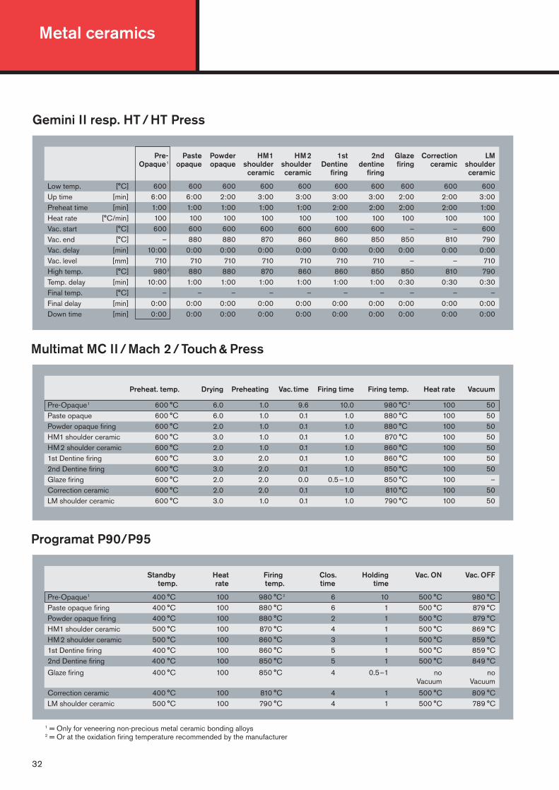
Low temp. [°C] 600 600 600 600 600 600 600 600 600 600Up time [min] 6:00 6:00 2:00 3:00 3:00 3:00 3:00 2:00 2:00 3:00Preheat time [min] 1:00 1:00 1:00 1:00 1:00 2:00 2:00 2:00 2:00 1:00Heat rate [°C/min] 100 100 100 100 100 100 100 100 100 100Vac. start [°C] 600 600 600 600 600 600 600 – – 600Vac. end [°C] – 880 880 870 860 860 850 850 810 790Vac. delay [min] 10:00 0:00 0:00 0:00 0:00 0:00 0:00 0:00 0:00 0:00Vac. level [mm] 710 710 710 710 710 710 710 – – 710High temp. [°C] 9802 880 880 870 860 860 850 850 810 790Temp. delay [min] 10:00 1:00 1:00 1:00 1:00 1:00 1:00 0:30 0:30 0:30Final temp. [°C] – – – – – – – – – –Final delay [min] 0:00 0:00 0:00 0:00 0:00 0:00 0:00 0:00 0:00 0:00Down time [min] 0:00 0:00 0:00 0:00 0:00 0:00 0:00 0:00 0:00 0:00
Gemini II resp. HT / HT Press
Programat P90/P95
Standby Heat Firing Clos. Holding Vac. ON Vac. OFFtemp. rate temp. time time
Pre-Opaque1 400 °C 100 980 °C 2 6 10 500 °C 980 °CPaste opaque firing 400 °C 100 880 °C 6 1 500 °C 879 °CPowder opaque firing 400 °C 100 880 °C 2 1 500 °C 879 °CHM1 shoulder ceramic 500 °C 100 870 °C 4 1 500 °C 869 °CHM2 shoulder ceramic 500 °C 100 860 °C 3 1 500 °C 859 °C1st Dentine firing 400 °C 100 860 °C 5 1 500 °C 859 °C2nd Dentine firing 400 °C 100 850 °C 5 1 500 °C 849 °C
Glaze firing 400 °C 100 850 °C 4 0.5–1 no noVacuum Vacuum
Correction ceramic 400 °C 100 810 °C 4 1 500 °C 809 °CLM shoulder ceramic 500 °C 100 790 °C 4 1 500 °C 789 °C
Multimat MC II / Mach 2 / Touch & Press
Preheat. temp. Drying Preheating Vac. time Firing time Firing temp. Heat rate Vacuum
Pre-Opaque1 600 °C 6.0 1.0 9.6 10.0 980 °C 2 100 50Paste opaque 600 °C 6.0 1.0 0.1 1.0 880 °C 100 50Powder opaque firing 600 °C 2.0 1.0 0.1 1.0 880 °C 100 50HM1 shoulder ceramic 600 °C 3.0 1.0 0.1 1.0 870 °C 100 50HM2 shoulder ceramic 600 °C 2.0 1.0 0.1 1.0 860 °C 100 501st Dentine firing 600 °C 3.0 2.0 0.1 1.0 860 °C 100 502nd Dentine firing 600 °C 3.0 2.0 0.1 1.0 850 °C 100 50Glaze firing 600 °C 2.0 2.0 0.0 0.5–1.0 850 °C 100 –Correction ceramic 600 °C 2.0 2.0 0.1 1.0 810 °C 100 50LM shoulder ceramic 600 °C 3.0 1.0 0.1 1.0 790 °C 100 50
1 = Only for veneering non-precious metal ceramic bonding alloys 2 = Or at the oxidation firing temperature recommended by the manufacturer

33
5. Firing charts
Programat X 1/ EP 600
B S t T H V % VE VAStandby Clos. Heat Firing Holding Vacuum Vac. Vac.
temp. time rate temp. time level ON OFF[°C] [min] [°C/min] [°C] [min] [%] [°C] [°C]
Pre-Opaque1 400 6:00 100 9802 10:00 100 500 T Paste opaque firing 400 6:00 100 880 1:00 100 500 1° below TPowder opaque firing 400 3:00 100 880 1:00 100 500 1° below THM1 shoulder ceramic 500 4:00 100 870 1:00 100 500 1° below THM2 shoulder ceramic 500 3:00 100 860 1:00 100 500 1° below T1st Dentine firing 400 6:00 100 860 1:00 100 500 1° below T2nd Dentine firing 400 6:00 100 850 1:00 100 500 1° below T
Glaze firing 400 4:00 100 850 0:30 – no no Correction ceramic 400 4:00 100 810 1:00 100 500 1° below TLM shoulder ceramic 500 4:00 100 790 1:00 100 500 1° below T
Systomat
Left firing chamber Right firing chamber Cooling phaseTemp. Time Vac. Temp. Time
Pre-Opaque1 980 °C 2 5 4.5 600 °C 2 –Paste opaque firing 880 °C 3 2 600 °C 2 –Powder opaque firing 880 °C 3 2 600 °C 2 –HM1 shoulder ceramic 870 °C 5 4 600 °C 2 –HM2 shoulder ceramic 860 °C 3 2 600 °C 2 –1st Dentine firing 860 °C 3 2 600 °C 2–4 –2nd Dentine firing 850 °C 3 2 600 °C 2–4 –
Glaze firing 850 °C 2–3 – 600 °C 2 –Correction ceramic 810 °C 2–3 2 600 °C 2 –LM shoulder ceramic 790 °C 3 2 600 °C 2 –
1 = Only for veneering non-precious metal ceramic bonding alloys 2 = Or at the oxidation firing temperature recommended by the manufacturer
Vacumat 200/250/300
Standby Final Predrying Heat Holding Vac. timetemp. temp. time rate time
Pre-Opaque1 600 °C 980 °C 2 6.0 3.0 10.0 12.5Paste opaque firing 600 °C 880 °C 6.0 3.0 2.0 3.0Powder opaque firing 600 °C 880 °C 3.0 3.0 1.0 3.0HM1 shoulder ceramic 600 °C 870 °C 4.0 3.0 1.0 3.0HM2 shoulder ceramic 600 °C 860 °C 3.0 3.0 1.0 3.01st Dentine firing 600 °C 860 °C 5.0 3.0 1.0 3.02nd Dentine firing 600 °C 850 °C 5.0 3.0 1.0 3.0Glaze firing 600 °C 850 °C 4.0 3.0 0.5–1.0 0.0Correction ceramic 600 °C 810 °C 5.0 3.0 1.0 3.0LM shoulder ceramic 600 °C 790 °C 4.0 3.0 1.0 3.0
Metal ceramics
34
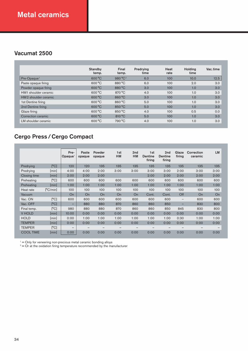
1 = Only for veneering non-precious metal ceramic bonding alloys 2 = Or at the oxidation firing temperature recommended by the manufacturer
Vacumat 2500
Standby Final Predrying Heat Holding Vac. timetemp. temp. time rate time
Pre-Opaque1 600 °C 980 °C 2 6.0 100 10.0 12.5Paste opaque firing 600 °C 880 °C 6.0 100 2.0 3.0Powder opaque firing 600 °C 880 °C 3.0 100 1.0 3.0HM1 shoulder ceramic 600 °C 870 °C 4.0 100 1.0 3.0HM2 shoulder ceramic 600 °C 860 °C 3.0 100 1.0 3.01st Dentine firing 600 °C 860 °C 5.0 100 1.0 3.02nd Dentine firing 600 °C 850 °C 5.0 100 1.0 3.0Glaze firing 600 °C 850 °C 4.0 100 0.5 0.0Correction ceramic 600 °C 810 °C 5.0 100 1.0 3.0LM shoulder ceramic 600 °C 790 °C 4.0 100 1.0 3.0
Pre- Paste Powder 1st 2nd 1st 2nd Glaze Correction LMOpaque1 opaque opaque HM HM Dentine Dentine firing ceramic
firing firing
Predrying [°C] 120 120 135 135 135 135 135 135 135 135Predrying [min] 4:00 4:00 2:00 3:00 3:00 3:00 3:00 2:00 3:00 3:00Closing time [min] 2:00 2:00 2:00 2:00 2:00 2:00 2:00 2:00Preheating [°C] 600 600 600 600 600 600 600 600 600 600Preheating [min] 1:00 1:00 1:00 1:00 1:00 1:00 1:00 1:00 1:00 1:00Heat rate [°C/min] 100 100 100 100 100 100 100 100 100 100Vacuum On On On On On Cont. Cont. Off On OnVac. ON [°C] 600 600 600 600 600 600 600 – 600 600Vac. OFF [°C] – 880 880 870 860 860 850 – 830 800Final temp. [°C] 980 880 880 870 860 860 850 845 830 800V HOLD [min] 10:00 0:00 0:00 0:00 0:00 0:00 0:00 0:00 0:00 0:00HOLD [min] 0:00 1:00 1:00 1:00 1:00 1:00 1:00 0:30 1:00 1:00TEMPER [min] 0:00 0:00 0:00 0:00 0:00 0:00 0:00 0:00 0:00 0:00TEMPER [°C] – – – – – – – – – –COOL TIME [min] 0:00 0:00 0:00 0:00 0:00 0:00 0:00 0:00 0:00 0:00
Cergo Press / Cergo Compact

35
Laser welding parameters for ceramic bonding alloys to be entered into the Herapuls unit
Program Alloys Working Focus Ø Power Time Welding- OtherNr. step [mm] [kW] [ms] wire
9 Ceramic bonding alloys bridge 0.8 1.9 7 no Welding withoute.g.: Herador C, Herador H, Ø 3 – 4 mm wire/fasteningHerador NH, Herador S, Herador G, Herador GG, Heraloy G, Herabond, Herabond N, Albabond A, Albabond B
10 with wire 0.9 1.8 7 yes Weldingon wire
11 smoothing 1.4 1.8 7 no Smoothing
12 Bio alloys bridge 0.7 2 3.2 no Welding withoute.g.: Bio Herador N, Ø 3 – 4 mm wire/fasteningBio Herador SG, Herador EC,Herador PF, Herador MP
13 with wire 0.85 1.8 3.2 yes Weldingon wire
14 smoothing 1.2 2.1 3.2 no Smoothing
Tear-out page

Metal ceramicsNotes

0010
0221
3C
10.0
5 V
N/A
BC
MH
Prin
ted
in G
erm
any
0483Germany: Heraeus Kulzer GmbHGrüner Weg 1163450 Hanau, GermanyFax: +49 618135 5013E-Mail: [email protected]
United Kingdom:Heraeus Kulzer Ltd.Heraeus HouseAlbert Road/Northbrook StreetRG14 1DL Newbury, BerkshirePhone: +441635 30500Fax: +441635 524622
Scandinavia: Heraeus Kulzer Nordic ABHammarbacken 419149 SOLLENTUNABox 43719124 SollentunaPhone: +46 85 857 7755Fax: +46 86 231 413www.heraeus.se
Australia:Heraeus Kulzer Australia Pty Ltd.3 Gibbes Street, Unit 4CHATSWOOD, N.S.W. 2067Phone: +6129 417 8411Fax: +6129 417 5093www.kulzer.com.au
Japan:Heraeus Kulzer Japan Co. Ltd.9F The Itoyama Tower Bldg.3-7-18 Mita Minato-kuTokyo 108-0073Phone: +81 3 5427 7261Fax: +81 3 5427 7269www.heraeus-kulzer.co.jp
China:Heraeus Kulzer Dental Ltd.680 Guiping Road200233 ShanghaiPhone: +86 21 649 58488Fax: +86 21 649 52279www.heraeus-kulzer.com.cn