Message-handling systems based on the CCITT X.400 ...€¦ · Message-handling systems based on the...
20
Message-handling systems based on the CCITT X.400 recommendations by T. E. Schutt J. B. Staton 111 W. F. Racke Message-handlingsystems allow the exchangeof elec- tronic mailbetween computers. The International Tele graph and Telephone Consultative Committee (CCITT) has proposed a standard for messagehandling sys- tems in the form of the X.400 series of recommenda- tions that has been widely recognized by computer manufacturers and communications carriers. This pa- per provides a tutorial on the X.400 recommendations and then describes two prototypes developedby the IBM European Networking Center in Heidelberg, Ger- many, in cooperation with its research partners. The prototypes were demonstrated together with X.400 prototypes from other manufacturers at the CeBlT 86 trade fair in Hannover, Germany. A pplication programs that cooperate with one another to perform the exchange of messages between computers or message-handling systems have been in use since the late 1960s. Many examples of such applications were constructed to provide message exchange or electronic mail within networks of computers offered by the same manufacturer. In IBM, examples of product offerings that include mes- sage-handling functionsarethe Distributed Office Support System (DISOSS) and the Professional Office System (PROFS).’ These products were constructed for exchanging messages within networks using Sys- tems Network Architecture (SNA) and Remote Spooling Communication Subsystem (RSCS) proto- cols under the Virtual Machine (VM) operating sys- tem, respectively. Another example is the mail trans- fer system in the Department of Defense Advance Research Projects Agency Network (ARPANET). During the period from 1980 to 1984, Study Group VI1 of the International Telegraph and Telephone IBM SYSTEMS JOURNAL, VOL 26, NO 3, 1987 Consultative Committee (CCITT) developed a set of recommendations for message-handling systems’ that allow computers of different manufacturers to exchange messages. The recommendations utilize the communications model and protocols that have been developed by the International Standards Or- ganization (ISO), while proposing new protocols to perform the message-handling application. In the fall of 1983, a reasonably complete set of eight new recommendations was released. These recommen- dations, approved by the cCITT in October 1984, are known collectively as the x.400 recommendations on message-handling systems (henceforth referred to simply as x.400). Since 1984, there have been a number of efforts by associations of manufacturers, public telephone and telegraph associations, and government-sponsored standards agencies3 directed at identifying reasonable subsets of function that can be implemented as well as providing guidance to implementers on ambigui- ties in the recommendations. These efforts have re- sulted in the definition of a number of x.400 func- tional standards or subsets of the X.400 protocols that can be implemented to allow different computers to exchange messages. Two key functionalstandards have been defined for X.400 that are often referred to as the CEPT and CEN/CENELEC profiles. The CEPT Copyright 1987 by International Business Machines Corporation. Copying in printed form for private use is permitted without payment of royalty provided that (1) each reproduction is done without alteration and (2) the Journal reference and IBM copyright notice are included on the first page. The title and abstract, but no other portions, of this paper may be copied or distributed royalty free without further permission by computer-based and other information-service systems. Permission to republish anyother portion of this paper must be obtained from the Editor. SCHUTI ET AL 235
Transcript of Message-handling systems based on the CCITT X.400 ...€¦ · Message-handling systems based on the...

Message-handling systems based on the CCITT X.400 recommendations
by T. E. Schutt J. B. Staton 111 W. F. Racke
Message-handling systems allow the exchange of elec- tronic mail between computers. The International Tele graph and Telephone Consultative Committee (CCITT) has proposed a standard for messagehandling sys- tems in the form of the X.400 series of recommenda- tions that has been widely recognized by computer manufacturers and communications carriers. This pa- per provides a tutorial on the X.400 recommendations and then describes two prototypes developed by the IBM European Networking Center in Heidelberg, Ger- many, in cooperation with its research partners. The prototypes were demonstrated together with X.400 prototypes from other manufacturers at the CeBlT 86 trade fair in Hannover, Germany.
A pplication programs that cooperate with one another to perform the exchange of messages
between computers or message-handling systems have been in use since the late 1960s. Many examples of such applications were constructed to provide message exchange or electronic mail within networks of computers offered by the same manufacturer. In IBM, examples of product offerings that include mes- sage-handling functions are the Distributed Office Support System (DISOSS) and the Professional Office System (PROFS).’ These products were constructed for exchanging messages within networks using Sys- tems Network Architecture (SNA) and Remote Spooling Communication Subsystem (RSCS) proto- cols under the Virtual Machine (VM) operating sys- tem, respectively. Another example is the mail trans- fer system in the Department of Defense Advance Research Projects Agency Network (ARPANET).
During the period from 1980 to 1984, Study Group VI1 of the International Telegraph and Telephone
IBM SYSTEMS JOURNAL, VOL 26, NO 3, 1987
Consultative Committee (CCITT) developed a set of recommendations for message-handling systems’ that allow computers of different manufacturers to exchange messages. The recommendations utilize the communications model and protocols that have been developed by the International Standards Or- ganization (ISO), while proposing new protocols to perform the message-handling application. In the fall of 1983, a reasonably complete set of eight new recommendations was released. These recommen- dations, approved by the cCITT in October 1984, are known collectively as the x.400 recommendations on message-handling systems (henceforth referred to simply as x.400).
Since 1984, there have been a number of efforts by associations of manufacturers, public telephone and telegraph associations, and government-sponsored standards agencies3 directed at identifying reasonable subsets of function that can be implemented as well as providing guidance to implementers on ambigui- ties in the recommendations. These efforts have re- sulted in the definition of a number of x.400 func- tional standards or subsets of the X.400 protocols that can be implemented to allow different computers to exchange messages. Two key functional standards have been defined for X.400 that are often referred to as the CEPT and CEN/CENELEC profiles. The CEPT
Copyright 1987 by International Business Machines Corporation. Copying in printed form for private use is permitted without payment of royalty provided that (1) each reproduction is done without alteration and (2) the Journal reference and IBM copyright notice are included on the first page. The title and abstract, but no other portions, of this paper may be copied or distributed royalty free without further permission by computer-based and other information-service systems. Permission to republish any other portion of this paper must be obtained from the Editor.
SCHUTI ET AL 235
functional standard has been defined for exchanging messages between private companies and message- handling systems operated by public telephone and telegraph companies (PTTS), and the CEN/CENELEC functional standard has been defined to describe the interfaces of message-handling systems operated by private companies.
A number of manufacturers in Europe, including IBM, began to demonstrate prototype message-han- dling systems based on the x.400 recommendations in 1985. In 1986, IBM participated with other man- ufacturers and nonprofit institutions to demonstrate the exchange Of x.400 messages at the CeBIT trade fair in H a n n o ~ e r . ~
The x.400 recommendations are important for sev- eral reasons. They are one of the first application layer standards (layer 7) of the ISO reference model for open systems interc~nnection,~ and, as such, they will influence the development of the services and protocols for other application layer standards.6 In fact, the X.409 recommendation on Presentation Transfer Syntax and Notation, which contains the description of the representational techniques used to specify and encode messages, has set the direction for the Abstract Syntax Notation 1 (ASN.~) . This notation is currently being defined in KO to be used to specify the data units of other application layer protocols.
The X.400 recommendations address an important application area for most users, that is, the area of electronic messaging in a heterogeneous environ- ment, and thus there is a high degree of user interest in progress toward their implementation. Further- more, other groups standardizing specific types of message transfer protocols, such as the Is0 TC68 committee on Banking and Related Financial Ser- vices, which is responsible for the standardization of electronic funds transfer protocols, will also be strongly influenced by the x.400 recommendations.
Finally, the availability of x.400 services through the public networks worldwide, as has already been an- nounced in many countries in Europe, also contrib- utes to its importance as an international standard.
Major concepts and terminology
The x.400 recommendations for message-handling systems2 consist of eight recommendations that to- gether define the services and protocols for message
236 SCHUTT ET AL
exchange in open systems. The eight recommenda- tions are the following:
x.400 System model-service elements x.401 Basic service elements and optional user facil-
X.408 Encoded-information-type conversion rules X.409 Presentation transfer syntax and notation X.410 Remote operations and reliable transfer server x.41 I Message transfer layer X.420 Interpersonal messaging user agent layer x.430 Access protocol for Teletex terminals
The first recommendation, X.400, provides an over- view of the message-handling system (MHS) model. In this model, a user is a person or an application program that sends or receives messages. When send- ing a message, the user is referred to as the originator of a message. When receiving a message, the user is referred to as a recipient of a message. The user prepares and receives messages through the assis- tance of a User Agent (uA), which is an application process that interfaces with the Message Transfer System (MTS) to submit and receive messages on the
ities
User agents could be such applications as electronic funds
transfer or services to interconnect university libraries.
user’s behalf. The message transfer system is the set of Message Transfer Agents (MTAS) that perform such functions as relaying the messages to the appro- priate destinations and providing safe storage for messages in transit.
As application entities in the KO reference model, the message transfer agent makes use of the Reliable Transfer Server (RTS) to establish session connections and reliably transfer messages through these connec- tions on behalf of the message transfer agent. If a connection becomes inactive, it is up to the RTS to re-establish the session and to continue the transfer
IBM SYSTEMS JOURNAL, VOL 26. NO 3, 1987
of the message until the transfer is complete. The specific user agent described in the x.420 recommen- dation is the Interpersonal Messaging (IPM) user agent. This user agent provides for the transfer of office mail to the message transfer system. Other user agents could be defined for such applications as electronic funds transfer in the banking industry or library services to interconnect university libraries.
In the physical mapping of the message-handling system, the user agent can reside in the same proc- essing system as the message transfer agent being accessed by I/O devices such as terminals attached to the processing system. The user agent can also reside in an intelligent workstation or processor that is separate from the processing system containing the message transfer agent. This is made possible by the definition in the x.400 recommendations of a sub- mission and delivery entity (SDE), which submits and receives messages from the MTA on the basis of a defined interface and specific SDE-MTA protocol. Or- ganizationally, the message transfer agents are grouped into udministration management domains (ADMDS) and private management domains (PRMDS). The administration management domains are the responsibility of the local network provider or na- tional carrier, whereas a private management do- main is maintained by a private organization or company. In the X.400 recommendations, it was en- visioned that private management domains would exchange messages with each other only, by first sending them through administration management domains and thus using the local camers to route the messages. Whether this actually occurs will de- pend upon the services provided by the various national camers and may vary from country to country. The form of the message itself, as it is transferred from originator to recipient, consists of an envelope and content, which are analogous to an envelope and letter sent through the postal system. The envelope contains the addresses of the recipients and the originator, in addition to other information such as whether the originator requires confirmation that the message has been delivered.
Actually, three envelopes are created during the en- tire process of delivering a message. The user agent submits the message to the MTA by transferring the content plus a submission envelope. The message is transferred from one MTA to another by means of a relaying envelope. The final MTA transfers the mes- sage to the recipient user agent by means of a delivery envelope.
IBM SYSTEMS JOURNAL, VOL 26 NO 3 1987
The content of the message consists of two parts, heading and body. The heading is analogous to the heading of an interoffice memo and contains infor- mation such as the originator, recipient, unique mes- sage identification, subject, and references to other messages. The body of the message is the actual information that the originator wishes to convey to the recipient. It is classified by body type, which describes the encoding scheme used for the infor- mation. Examples of currently defined body types include International Alphabet 5 (IA5) Text, Teletex, and Group 3 Facsimile (G3Fax).
The originator and recipient(s) of a message are identified by an OriginatorlRecipient name (OfR name). The O/R name may be supported in one of two basic forms. In the first form, the O/R name consists of a subset of the set of attributes as follows:
Country name Administration domain name Private domain name Personal name Organization name Organizational unit names Domain-defined attributes
In the second form, the O f R name consists simply of the x.121 address and, optionally, a telematic termi- nal identifier. Because the O/R name is also used for routing, it also serves as the address of the originator and recipient.
For migration purposes, a protocol is defined in the x.430 recommendation to allow Teletex terminals to access the message-handling system through the use of a special user agent known as a Teletex access unit (TTXAU).
Relationship to IS0 standards
To ensure widespread acceptance and to expedite the implementation of the x.400 recommendations, the CCITT decided to build upon existing ISO or CCITT communication standards. Draft standards already existed in 1984 for the lower five layers of the OSI reference model, and are simply referenced by the x.400 recommendations for message-handling sys- tems. Only the two highest layers (application and presentation layers) required specification by the CCITT.
Although the presentation layer is formally left empty by the x.400 model of a message-handling
SCH~JTT ET AL 237
~~ ~~ ~ ~ ~ ~~
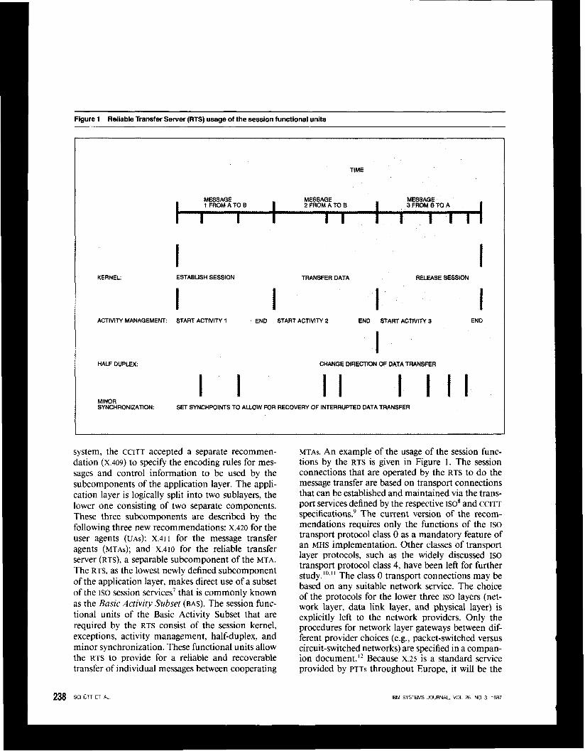
Figure 1 Reliable Transfer Sewer (FITS) usage of the session functional units ~~~ ~~
TIME
t I MESSAGE 1 FROM A TO B I
MESSAGE 2 FROM A TO B I MESSAGE
3FROMBTOA
I I I I I I t
I KERNEL: ESTABLISH SESSION
I ACTIVITY MANAGEMENT START ACTIVITY 1
HALF DUPLEX
MlMnn
TRANSFER DATA
I RELEASE SESSION
I END START ACTIVITY 2 END START ACTIVITY 3 END
I CHANGE DIRECTION OF DATA T W F E R
I I I I I I ......-. . SYNCHRONIZATION: SET SYNCHPOINTS TO ALLOW FOR RECOVERY OF INTERRUPTED DATA TRANSFER
system, the CCITT accepted a separate recommen- dation (x.409) to specify the encoding rules for mes- sages and control information to be used by the subcomponents of the application layer. The appli- cation layer is logically split into two sublayers, the lower one consisting of two separate components. These three subcomponents are described by the following three new recommendations: X.420 for the user agents (UAS); x.41 I for the message transfer agents (MTAS); and x.410 for the reliable transfer server (RTS), a separable subcomponent of the MTA. The RTS, as the lowest newly defined subcomponent of the application layer, makes direct use of a subset of the ISO session services' that is commonly known as the Basic Activity Subset (BAS). The session func- tional units of the Basic Activity Subset that are required by the RTS consist of the session kernel, exceptions, activity management, half-duplex, and minor synchronization. These functional units allow the RTS to provide for a reliable and recoverable transfer of individual messages between cooperating
MTAs. An example of the usage of the session func- tions by the RTS is given in Figure 1. The session connections that are operated by the RTS to do the message transfer are based on transport connections that can be established and maintained via the trans- port services defined by the respective ]SO8 and CCITT specifications? The current version of the recom- mendations requires only the functions of the ISO transport protocol class 0 as a mandatory feature of an MHS implementation. Other classes of transport layer protocols, such as the widely discussed ISO transport protocol class 4, have been left for further study.".'' The class 0 transport connections may be based on any suitable network service. The choice of the protocols for the lower three ISO layers (net- work layer, data link layer, and physical layer) is explicitly left to the network providers. Only the procedures for network layer gateways between dif- ferent provider choices (e.g., packet-switched versus circuit-switched networks) are specified in a compan- ion document." Because X.25 is a standard service provided by PTTS throughout Europe, it will be the
238 SCHUTT ET AL IBM SYSTEMS JOURNAL, VOL 26, NO 3, 1987

Figure 2 Sublayers and protocols of an interpersonal messaging system
USER AGENT SUBLAYER
TRANSFER MESSAGE
SUBLAYER
choice of the lower layers for most European imple- mentations of X.400.
We envision that in the future other transport pro- tocol classes will be incorporated into the CCITT X.400 recommendations and also into the ISO Message Oriented Text Interchange System (MOTIS) draft standards.13-16 Such enhancements could allow for a standardized usage of leased lines, local-area net- works (LANS), or Integrated Services Digital Networks (ISDNS).
The X.400 recommendations
The x.400 message transfer agent, submission and delivery entity, user agent, and the corresponding peer protocols for communication among the com- ponents reside at the application layer of the ISO Reference Model. The application layer is divided into the following two sublayers:
Message Transfer Layer (MTL), which contains the functions of the message transfer system as pro- vided by the message transfer agents and submis- sion and delivery entities User Agent Layer (UAL), which contains the func- tions provided by the user agents
This layered representation of the X.400 model for message-handling systems allows, in a manner sim- ilar to the layered OSI Reference Model, the identi- fication of unique entities in each of the two sublay- ers, the identification of the protocols used between peer entities, and the independent specification of the service interfaces for these entities. For the spe- cific case of the Interpersonal Messaging System, the different entities and their peer protocols are shown in Figure 2.
IBM SYSTEMS JOURNAL, VOL 26, NO 3. 1987
Message transfer layer. The x.41 I recommendation entitled Message-Handling Systems: Message Trans- fer Layer contains the specification of the message transfer services including the specification of the PI and ~3 protocols. The P I protocol is used for com- municating between MTAs, and the ~3 protocol is used between an MTA and an SDE. The services of the message transfer layer provide the user agent with the means for transferring messages to and from the message transfer system. The services can be requested by a user agent from its message transfer agent either directly, when both are located in the same processing system, or through the use of a submission and delivery entity, in the case of a remote user agent. In either case the services pro- vided to the user agent are the same.
Message transfer services. The service interface be- tween the message transfer layer and the user agent is described by a set of thirteen senlice primitives. (See Table 1.) The use of service primitives for the description of a service interface is an abstract way of capturing only those details of the interaction between two adjacent entities that are required for the layer service. Parameters are associated with a service primitive when it is necessary to transfer additional information between entities. A service primitive neither specifies nor constrains the imple- mentation of the entities or the service interface between them.”
The LOGON and LOGOFF service primitives establish and release a dialogue between the user agent and the message transfer agent. The establishment of a dialogue can be initiated either by the user agent via (UAL)LOGON, or by the message transfer layer via (MTL)LOGON. Only the user agent is able to release a
SCHUTT ET AL 239
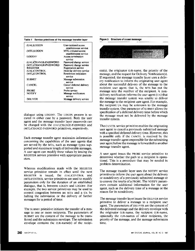
Table 1 Service primitives of the message transfer layer Figure 3 Structure of a user message
(UAL)LOGON User-initiated access
(MTL)LOGON MTL-initiated access
LOGOFF Access termination
(UAL)CWANGE-PASSWORD Password change service (MTL)CMANGE-PASSWORD Password change service REGISTER (UAL)CONTROL
Registration service
(MTL)CONTROL Hold for delivery service Restriction indication
SUBMIT Message submission
CANCEL
PROBE Probe service NOTIFY Message notification
DELIVER
establishment service
establishment service
service
service
service
service Cancel deferred delivery
service Message delivery service
dialogue using LOGOFF. The LOGON process is se- cured in either case by a password. Both the user agent and the message transfer layer passwords can
(MTLKHANGE-PASSWORD primitives, respectively. be changed with the (UAL)CHANGE-PASSWORD and
Each message transfer agent maintains information concerning the capabilities of the user agents that are served by the MTA, such as message types sup- ported and maximum length of deliverable messages. A user agent can modify these values by issuing the REGISTER service primitive with appropriate param- eters.
Whereas modifications made with the REGISTER service primitive remain in effect until the next REGISTER is issued, the (UALKONTROL and (MTL)CONTROL service primitives are used to modify parameters only for the duration of an established dialogue, that is, between LOGON and LOGOFF. For example, the two service primitives may be used to control congestion between an MTA and a UA by halting the submission or the delivery of further messages for a period of time.
The SUBMIT primitive initiates the transfer of a mes- sage to one or more recipients. The parameters of SUBMIT are the content of the message to be trans- ferred and the submission envelope. The submission envelope contains the o/R-name@) of the recipi-
ent(s), the originator o/R-name, the priority of the message, and the request for Delivery Notification(s). If requested, the message transfer layer uses a deliv- ery notification to inform the originating user agent about the successful delivery of the message to the recipient user agent; that is, the MTS has put the message into the mailbox of the recipient. A non- delivery notification informs the user agent (UA) that the message transfer system was unable to deliver the message to the recipient user agent. For example, the recipient UA may be unknown to the message transfer system. One parameter of SUBMIT allows the specification of a deferred delivery time before which the message must not be delivered by the message transfer system.
The CANCEL service primitive enables the originating user agent to cancel a previously submitted message with a specified deferred delivery time. However, this is possible only if the CANCEL is received by the message transfer agent responsible for the submitting user agent before the message is forwarded to another message transfer agent.
A user agent issues the PROBE service primitive to determine whether the path to a recipient is opera- tional. This is a procedure that may be needed in problem determination.
The message transfer layer uses the NOTIFY service primitive to inform the user agent about the delivery or nondelivery of a previously submitted message or to convey the results of a PROBE. The NOTIFY param- eters contain additional information for the user agent, such as the delivery time of a message or the reason for its nondelivery.
The message transfer layer issues the DELIVER service primitive to deliver a message to a recipient user agent. The parameters of DELIVER are the content of the delivered message and the delivery envelope with the originator O/R-name, the recipient O/R-name, optionally the O/R-nameS of other recipients, the priority of the message, and the message submission time.
IBM SYSTEMS JOURNAL, VOL 26, NO 3, 1987

Figure 4 Envelopes involved in the submission, relaying, and delivery of a message
I I ENVELOPE SUBMISSION
+CONTENT
DELIVERY ENVELOPE t I
+CONTENT
Message transfer agents and the PI protocol. Some of the service primitives described in the previous section are provided locally in a single message trans- fer agent and do not depend upon communication between MTAS. These include LOGON, LOGOFF, and REGISTER. The other service elements, such as SUB- M I T and PROBE, require the cooperation of message transfer agents, which is achieved by means of the message transfer, or P I protocol.
The PI protocol transfers message protocol data units (MPDUS) of three types. These are a user MPDU car- rying a message from one message transfer agent to another, a delivery report MPDU to transfer delivery or nondelivery information, and a probe MPDU.
The user MPDU consists of two parts: the relaying envelope and the message content, as shown in Fig- ure 3. The relaying envelope contains the informa- tion necessary for the cooperation of message trans- fer agents for relaying the message. The envelope is constructed by the MTA serving the originating user agent from the information contained in the sub- mission envelope. The following are the basic fields of the relaying envelope:
MPDU identifier Originator o/R-name Recipient o/R-name
Deferred delivery time Trace information
Priority
The relaying envelope is encoded in a bit string according to the encoding rules of the X.409 recom- mendation. The encoded envelope and the message content are then transferred to the next MTA. The message content is transparent to the message trans- fer system. While being transferred through the mes- sage transfer system, certain fields of the relaying envelope are modified to reflect the status of the message. An example is the trace information that is added by each message transfer agent through which the message passes. The MTA that is serving the recipient user agent uses the relaying envelope to create the delivery envelope. The delivery envelope together with the message content is passed to the recipient user agent by means of the DELIVER service primitive. The different envelopes and their relation- ship are depicted in Figure 4.
A further refinement of the MTA into its three sub- components illustrates in more detail the functions
IEM SYSTEMS JOURNAL, VOL 26. NO 3, 1987

Figure 5 Associations with adjacent Message Transfer Agents (MTAs)
performed by an MTA when interacting with other MTAS using the P I protocol. These three subcompo- nents are the Message Dispatcher, the Association Manager, and the Reliable Transfer Server (RTS). The relationship of these components within the MTA is shown in Figure 5.
The message dispatcher processes the PI protocol and is driven by MPDUS received from other message transfer agents and by messages or probes initiated by the user agents of the MTA. One of the functions performed by the message dispatcher is the genera- tion of the Delivery Report MPDUS. When relaying a message the message dispatcher uses the recipient o/R-name to determine the routing and address in- formation for forwarding the message to the next message transfer agent(s). Copies of the message are created and transferred to different MTAS in the event that the recipients of the message are reached via different paths within the message transfer system.
T able 2 Service primitives of the Reliable Transfer Server W S )
OPEN Establishment of an association CLOSE Release of an association TURN-PLEASE Request for exchange of the turn TURN-GIVE Exchange of the turn TRANSFER Reliable transfer of an
EXCEPTION Indication of transfer failure application protocol data unit
The message dispatcher transfers an MPDU to an adjacent message transfer agent in a single transac- tion over an association, which is a logical relation- ship between peer entities for the exchange of pro- tocol data units. As defined in the OSI Reference Model, associations are realized through connections of the next lower layer. Both the association manager and the reliable transfer server provide the functions to support the message dispatcher’s single-transac- tion view of the message transfer. The association manager initiates and controls the establishment and the release of associations, whereas the reliable trans- fer server is responsible for providing associations and for completely and reliably transferring MPDUS by means of them.
The RTS provides the MTA with a simplified interface to the session layer that allows an MPDU to be trans- ferred in a single transaction. A set of six service primitives for the reliable transfer server is described in the x.410 recommendation, as shown in Table 2.
The OPEN and CLOSE service primitives are used respectively by the message transfer agent to initiate the establishment of an association for the transfer of Application Protocol Data Units (APDUS) or to release an existing association. The reliable transfer server provides two-way-alternate (half-duplex) as-
exchange the right to send data over an association. With the TRANSFER service primitive, the reliable transfer of data is requested. The reliable transfer server informs the MTA by way of the EXCEPTION primitive in the event that it cannot complete the requested transfer of data.
sociations. TURN-PLEASE and TURN-GIVE request and
Submission and delivery entities and the P3 protocol. User agents request the services of the message trans- fer layer through the message transfer agent that serves the UAS. In the case of a remote user agent, where the UA and the MTA reside in different proc- essing systems, a special way to interconnect them
IBM SYSTEMS JOURNAL, VOL 26, NO 3, 1987
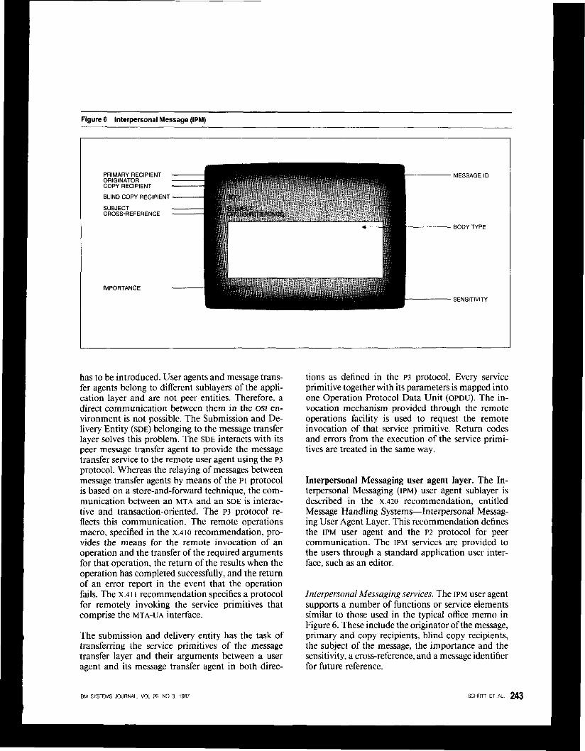
Figure 6 Interpersonal Message (IPM)
PRIMARY RECIPIENT ORIGINATOR COPY RECIPIENT
BLIND COPY RECIPIENl
SUBJECT CROSS-REFERENCE
IMPORTANCE
MESSAGE ID
BODY TYPE
SENSITIVITY
has to be introduced. User agents and message trans- fer agents belong to different sublayers of the appli- cation layer and are not peer entities. Therefore, a direct communication between them in the OSI en- vironment is not possible. The Submission and De- livery Entity (SDE) belonging to the message transfer layer solves this problem. The SDE interacts with its peer message transfer agent to provide the message transfer service to the remote user agent using the ~3 protocol. Whereas the relaying of messages between message transfer agents by means of the PI protocol is based on a store-and-forward technique, the com- munication between an MTA and an SDE is interac- tive and transaction-oriented. The ~3 protocol re- flects this communication. The remote operations macro, specified in the x.410 recommendation, pro- vides the means for the remote invocation of an operation and the transfer of the required arguments for that operation, the return of the results when the operation has completed successfully, and the return of an error report in the event that the operation fails. The x.41 I recommendation specifies a protocol for remotely invoking the service primitives that comprise the MTA-UA interface.
The submission and delivery entity has the task of transferring the service primitives of the message transfer layer and their arguments between a user agent and its message transfer agent in both direc-
IBM SYSTEMS JOURNAL, VOL 26. NO 3, 1987
tions as defined in the ~3 protocol. Every service primitive together with its parameters is mapped into one Operation Protocol Data Unit (OPDU). The in- vocation mechanism provided through the remote operations facility is used to request the remote invocation of that service primitive. Return codes and errors from the execution of the service primi- tives are treated in the same way.
Interpersonal Messaging user agent layer. The In- terpersonal Messaging (IPM) user agent sublayer is described in the x.420 recommendation, entitled Message Handling Systems-Interpersonal Messag- ing User Agent Layer. This recommendation defines the IPM user agent and the ~2 protocol for peer communication. The IPM services are provided to the users through a standard application user inter- face, such as an editor.
Interpersonal Messaging services. The IPM user agent supports a number of functions or service elements similar to those used in the typical office memo in Figure 6 . These include the originator ofthe message, primary and copy recipients, blind copy recipients, the subject of the message, the importance and the sensitivity, a cross-reference, and a message identifier for future reference.
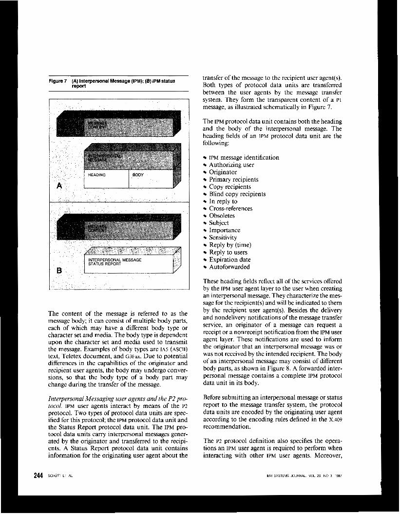
Figure 7 (A) Interpersonal Message (IPM); (B) IPM status report
n F
The content of the message is referred to as the message body; it can consist of multiple body parts, each of which may have a different body type or character set and media. The body type is dependent upon the character set and media used to transmit the message. Examples of body types are I A ~ (ASCII) text, Teletex document, and G3Fax. Due to potential differences in the capabilities of the originator and recipient user agents, the body may undergo conver- sions, so that the body type of a body part may change during the transfer of the message.
Interpersonal Messaging user agents and the P2 pro- tocol. IPM user agents interact by means of the ~2 protocol. Two types of protocol data units are spec- ified for this protocol; the IPM protocol data unit and the Status Report protocol data unit. The IPM pro- tocol data units carry interpersonal messages gener- ated by the originator and transferred to the recipi- ents. A Status Report protocol data unit contains information for the originating user agent about the
244 sc~un ET AL
transfer of the message to the recipient user agent(s). Both types of protocol data units are transferred between the user agents by the message transfer system. They form the transparent content of a PI message, as illustrated schematically in Figure 7.
The IPM protocol data unit contains both the heading and the body of the interpersonal message. The heading fields of an IPM protocol data unit are the following:
IPM message identification Authorizing user Originator Primary recipients Copy recipients Blind copy recipients In reply to Cross-references Obsoletes Subject Importance Sensitivity Reply by (time) Reply to users Expiration date Autoforwarded
These heading fields reflect all of the services offered by the IPM user agent layer to the user when creating an interpersonal message. They characterize the mes- sage for the recipient(s) and will be indicated to them by the recipient user agent(s). Besides the delivery and nondelivery notifications of the message transfer service, an originator of a message can request a receipt or a nonreceipt notification from the IPM user agent layer. These notifications are used to inform the originator that an interpersonal message was or was not received by the intended recipient. The body of an interpersonal message may consist of different body parts, as shown in Figure 8. A forwarded inter- personal message contains a complete IPM protocol data unit in its body.
Before submitting an interpersonal message or status report to the message transfer system, the protocol data units are encoded by the originating user agent according to the encoding rules defined in the x.409 recommendation.
The ~2 protocol definition also specifies the opera- tions an IPM user agent is required to perform when interacting with other IPM user agents. Moreover,
IEM SYSTEMS JOURNAL, VOL 26, NO 3, 1987
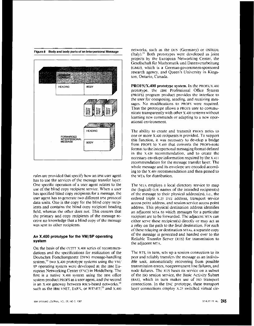
Figure 8 Body and body parts of an Interpersonal Message
FORWARDED
MESSAGE iNTERPERSONAL FORWARI
ME iNTERPEF
rules are provided that specify how an IPM user agent has to use the services of the message transfer layer. One specific operation of a user agent relates to the use of the blind copy recipient service. When a user has specified blind copy recipients for a message, the user agent has to generate two different IPM protocol data units. One is the copy for the blind copy recip- ients and contains the blind copy recipient heading field, whereas the other does not. This ensures that the primary and copy recipients of the message re- ceive no knowledge that a blind copy of the message was sent to other recipients.
An X.400 prototype for the VM/SP operating system
On the basis of the CCITT x.400 series of recommen- dations and the specifications for realization of the Deutsches Forschungsnetz (DFN) message-handling system,18 two x.400 prototype systems using the VM/ SP operating system were developed at the IBM Eu- ropean Networking Center (ENC) in Heidelberg. The first is a native x.400 system using the IBM office system product PROFS as a user agent, and the second is an x.400 gateway between Rscs-based networks,” such as the IBM VNET, EARN, or BITNET;20 and X.400
networks, such as the DFN (Germany) or OSIRIDE (Italy).21 Both prototypes were developed as joint projects by the European Networking Center, the Gesellschaft fur Mathematik und Datenverarbeitung (GMD), which is a German-government-sponsored research agency, and Queen’s University in Kmgs- ton, Ontario, Canada.
PROFS/XAOO prototype system. In the PROFS/X.400 prototype, the IBM Professional Office System (PROFS) program product provides the interface to the user for composing, sending, and receiving mes- sages. No modifications to PROFS were required. Thus the prototype allows a PROFS user to commu- nicate transparently with other x.400 systems without learning new commands or adapting to a new oper- ational environment.
The ability to create and transmit PROFS notes to one or more x.400 recipients is provided. To support this function, it was necessary to develop a bridge
format to the interpersonal messaging format defined in the x.420 recommendation, and to create the necessary envelope information required by the X.41 I recommendation for the message transfer layer. The whole message and its envelope are encoded accord- ing to the X.409 recommendation and then passed to the MTA for distribution.
The MTA employs a local directory service to map the (logical) O/R names of the intended recipient(s) of the message to their physical address(es), i.e., the ordered triple x.25 DTE address, transport service access point address, and session service access point address. This physical destination address identifies an adjacent MTA to which messages for a particular recipient are to be forwarded. The adjacent MTA can either serve these recipient(s) directly or may act as a relay on the path to the final destination. For each of these relaying or destination MTAs, a separate copy of the message is generated and handed over to the Reliable Transfer Server (RTS) for transmission to the adjacent MTA.
The RTS, in turn, sets up a session connection to its peer and reliably transfers the message as an indivis- ible unit, automatically recovering from possible transmission errors, nonpermanent line failures, and node failures. The RTS bases its service on a subset of the ISO session service, the Basic Activity Subset (BAS), which in turn makes use of ISO transport connections. In the ENC prototype, these transport layer connections employ x.25 switched virtual cir-
from PROFS to X.400 that converts the PROFS-note
IBM SYSTEMS JOURNAL, VOL 26. NO 3, 1987
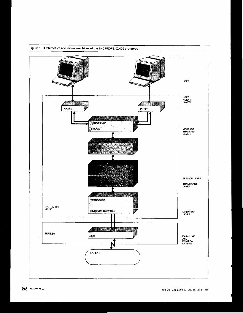
Figure 9 Architecture and virtual machines of the ENC PROFS/X .400 prototype
USER
I i
I+ I4
SYSTEMI370 VMISP
SERIES/l
i DATEX-P
AGENT USER
LAYER
MESSAGE TRANSFER LAYER
SESSION LAYER
TRANSPORT LAYER
NETWORK LAYER
DATA LINK AN0 PHYSICAL LAYERS
246 SCHUTT ET AL IBM SYSTEMS JOURNAL, VOL 26. NO 3, 1987
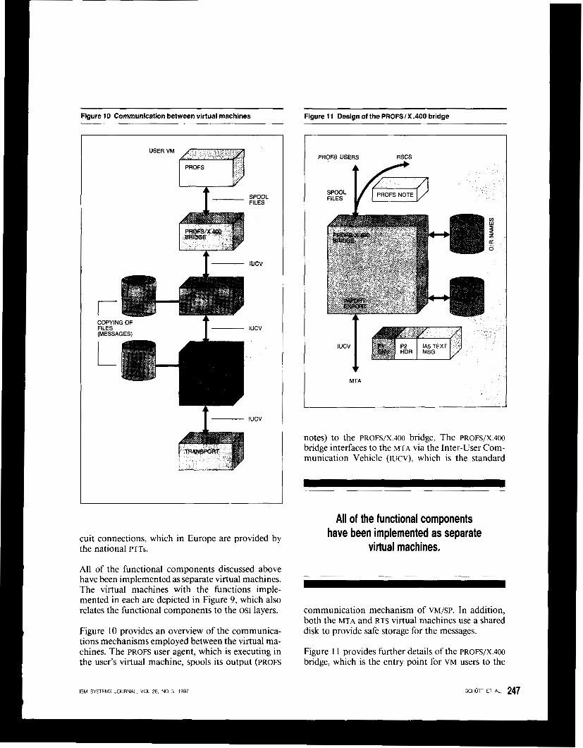
Figure IO Communication between virtual machines Figure 11 Design of the PROFSlX .400 bridge -
t SPOOL FILES
I - IUCV
COPYING OF FILES (UESSAGESI T" IUCV
1"- IUCV
cuit connections, which in Europe are provided by the national PTTs.
All of the functional components discussed above have been implemented as separate virtual machines. The virtual machines with the functions imple- mented in each are depicted in Figure 9, which also relates the functional components to the OSI layers.
Figure 10 provides an overview of the communica- tions mechanisms employed between the virtual ma- chines. The PROFS user agent, which is executing in the user's virtual machine, spools its output (PROFS
PROFS USERS RSCS
FILES PROFS NOTE
UTA
notes) to the PROFS/X.400 bridge. The P ~ o F s / X . 4 0 0 bridge interfaces to the MTA via the Inter-User Com- munication Vehicle (IUCV), which is the standard
All of the functional components have been implemented as separate
virtual machines.
communication mechanism of VM/SP. In addition, both the MTA and RTS virtual machines use a shared disk to provide safe storage for the messages.
Figure 1 1 provides further details of the PROFS/X.400 bridge, which is the entry point for VM users to the
IBM SYSTEMS JOURNAL VOL 26, NO 3, 1987
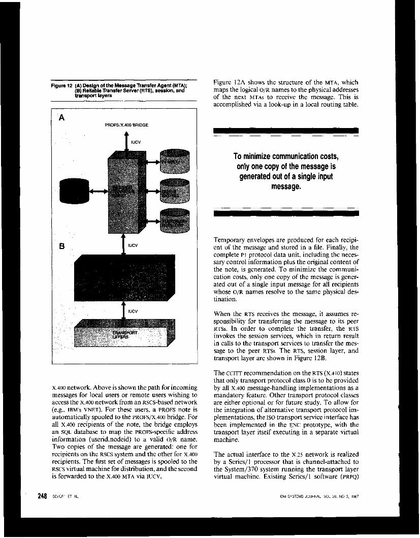
Figure 12 A) Design of the Message Transfer Agent (MTA); {e) Reliable Transfer Server (RTS), session. and transport layers
A PROFSIX.400 BRlDGE
1 IUCV
x.400 network. Above is shown the path for incoming messages for local users or remote users wishing to access the x.400 network from an Rscs-based network (e.g., IBM's VNET). For these users, a PROFS note is automatically spooled to the PROFS/X.400 bridge. For all X.400 recipients of the note, the bridge employs an SQL database to map the PROFS-specific address information (userid,nodeid) to a valid O/R name. Two copies of the message are generated: one for recipients on the RSCS system and the other for X.400 recipients. The first set of messages is spooled to the RSCS virtual machine for distribution, and the second is forwarded to the X.400 MTA via IUCV.
248 SCHUTT ET AL
Figure 12A shows the structure of the MTA, which maps the logical O/R names to the physical addresses of the next MTAS to receive the message. This is accomplished via a look-up in a local routing table.
To minimize communication costs, only one copy of the message is generated out of a single input
message.
Temporary envelopes are produced for each recipi- ent of the message and stored in a file. Finally, the complete PI protocol data unit, including the neces- sary control information plus the original content of the note, is generated. To minimize the communi- cation costs, only one copy of the message is gener- ated out of a single input message for all recipients whose O/R names resolve to the same physical des- tination.
When the RTS receives the message, it assumes re- sponsibility for transferring the message to its peer RTSs. In order to complete the transfer, the RTS invokes the session services, which in return result in calls to the transport services to transfer the mes- sage to the peer RTSS. The RTS, session layer, and transport layer are shown in Figure 12B.
The CCITT recommendation on the RTS (x.410) states that only transport protocol class 0 is to be provided by all x.400 message-handling implementations as a mandatory feature. Other transport protocol classes are either optional or for future study. To allow for the integration of alternative transport protocol im- plementations, the ISO transport service interface has been implemented in the ENC prototype, with the transport layer itself executing in a separate virtual machine.
The actual interface to the x.25 network is realized by a Series/l processor that is channel-attached to the System/370 system running the transport layer virtual machine. Existing Series/ 1 software (PRPQ)
IBM SYSTEMS JOURNAL, VOL 26. NO 3, 1987
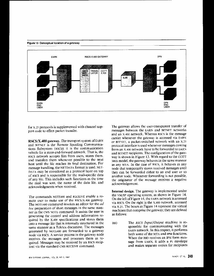
Figure 13 Conceptual location of a gateway
EARN RSCSIX.400 GATEWAY DFN
EARN END USER
DFN END USER
for x.25 protocols is supplemented with channel sup- port code to effect packet transfer.
RSCS/XAOO gateway. The transport system of EARN and BITNET is the Remote Spooling Communica- tions Subsystem (RSCS); it is the communication vehicle for a store-and-forward network. That is, the RSCS network accepts files from users, stores them, and transfers them whenever possible to the next host until the file reaches its final destination. For message handling, the NETDATA format is used. NET- DATA may be considered as a protocol layer on top of RSCS and is responsible for the mail-specific data of any file. This includes such functions as the time the mail was sent, the name of the data file, and acknowledgments when received.
The commands ~ o T E 4 0 0 and RECEIVE enable a re- mote user to make use of the RSCS/X.400 gateway. The ~ 0 ~ ~ 4 0 0 command invokes an editor for the ad hoc preparation of short messages in the same man- ner as the CMS NOTE command. It assists the user in generating the control and address information re- quired by the x.400 specifications and stores them into a message file that is internally structured in the same manner as a Teletex document. The messages generated by ~ 0 ~ ~ 4 0 0 are forwarded to a gateway node via RSCS. A service process in the gateway node receives the messages and processes them as re- quired. Messages may be received by an RSCS recip- ient via the standard CMS RECEIVE command.
IEM SYSTEMS JOURNAL, VOL 26, NO 3, 1987
The gateway allows the user-transparent transfer of messages between the EARN and BITNET networks and an x.400 network. Whereas RSCS is the message carrier whenever the gateway is accessed via EARN or BITNET, a packet-switched network with an x.25 protocol interface is used whenever messages coming from an x.400 network have to be forwarded to EARN and BITNET recipients. The configuration of the gate- way is shown in Figure 13. With regard to the CCITT MHS model, the gateway behaves in the same manner as any MTA. In the case of RSCS, it behaves as any node that temporarily stores received messages until they can be forwarded either to an end user or to another node. Whenever forwarding is not possible, the originator of the message receives a negative acknowledgement.
Internal design. The gateway is implemented under the vM/SP operating system, as shown in Figure 14. On the left of Figure 14, the EARN network is accessed via RSCS. On the right is the X.400 network, accessed via X.25. The boxes in Figure 14 represent the virtual machines that comprise the gateway; they are defined as follows:
RIO The RSCS Inputloutput machine is re- sponsible for communicating with the EARN network. In this respect, it performs both some of the MTA and IPM functions. When the RIO receives an IPM form mes- sage from EARN, it adds a PI envelope and makes separate copies for recipients
SCHUTT ET AL 249

Figure 14 Overall structure of an RSCS-to-X.400 gateway , STORAGE STORAGE , FILE FILE
(X.400 NETWORK,
with different addresses. The inverse of these operations takes place when a mes- sage from D m is received for EARN. RIO is also responsible for creating any re- quested delivery notifications for mes- sages that are transmitted from DFN to EARN.
MPM In addition to the functions of a relaying MTA, the Message Protocol Mapper is responsible for the format conversions between the EARN internal message struc- ture and the formats used within x.400. This conversion includes not only the encoding of the control information ac- cording to the x.409 encoding scheme but also any required content conversions [e.g., EBCDIC to International Alphabet No. 5 (IA5)].
RTS The Reliable Transfer Service and the underlying service machines are identical to the respective components of the PROFS/X.400 system.
DIRM The DIRM is the Directory Manager of all DFN subscribers who are known by the gateway. The directory contains routing and other delivery information for use by RIO and MPM.
Future enhancements. Because of the complexity and incompleteness of the X.400 recommendations, there
250 SCHUn ET AL
were attempts almost immediately by a number of standards interpretation bodies to define consistent subsets that could be implemented. At this time, there exist two widely accepted proposals. The first is the subset defined by the CENICENELEC functional standard; the second is the CEPT profile specified by the association of the European PTTs.
Manufacturers participating with IBM in the demonstration included
Siemens, Bull, ICL, and Nixdorf, as well as the scientific institution GMD
and the DFN-Verein.
On the basis of this work, the European Research Networks department of the ENC is continuing to enhance the X.400 prototypes to support all parame- ters and options that will be required by these two standardization bodies. To complete this work, ad- ditional function at the user interface is required that was not available in the first version of the x.400 prototypes.
IEM SYSTEMS JOURNAL. VOL 26. NO 3, 1987
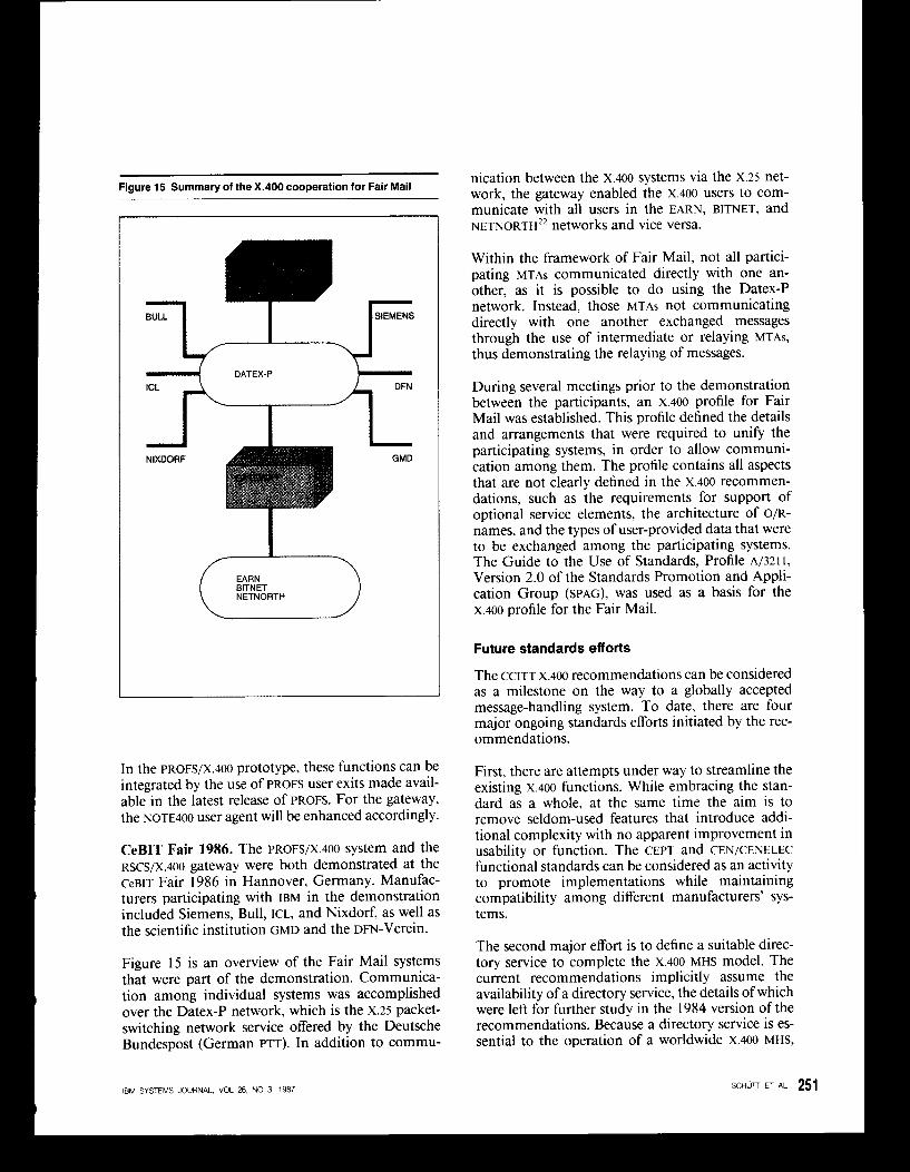
Figure 15 Summary of the X.400 cooperation for Fair Mail
L J " - 4 s ' E M E N s d DATEX-P *
In the PROFS/X.~OO prototype, these functions can be integrated by the use of PROFS user exits made avail- able in the latest release of PROFS. For the gateway, the ~ 0 ~ ~ 4 0 0 user agent will be enhanced accordingly.
CeBIT Fair 1986. The PROFS/X.400 system and the RSCS/X.~OO gateway were both demonstrated at the CeBIT Fair 1986 in Hannover, Germany. Manufac- turers participating with IBM in the demonstration included Siemens, Bull, ICL, and Nixdorf, as well as the scientific institution GMD and the Dm-Verein.
Figure 15 is an overview of the Fair Mail systems that were part of the demonstration. Communica- tion among individual systems was accomplished over the Datex-P network, which is the X.25 packet- switching network service offered by the Deutsche Bundespost (German PTT). In addition to commu-
IBM SYSTEMS JOURNAL, VOL 2 6 , NO 3, 1987
nication between the x.400 systems via the x.25 net- work, the gateway enabled the x.400 users to com- municate with all users in the EARN, BITNET, and NETNORTH" networks and vice versa.
Within the framework of Fair Mail, not all partici- pating MTAS communicated directly with one an- other, as it is possible to do using the Datex-P network. Instead, those MTAS not communicating directly with one another exchanged messages through the use of intermediate or relaying MTAs, thus demonstrating the relaying of messages.
During several meetings prior to the demonstration between the participants, an x.400 profile for Fair Mail was established. This profile defined the details and arrangements that were required to unify the participating systems, in order to allow communi- cation among them. The profile contains all aspects that are not clearly defined in the x.400 recommen- dations, such as the requirements for support of optional service elements, the architecture of O/R- names, and the types of user-provided data that were to be exchanged among the participating systems. The Guide to the Use of Standards, Profile A/321 I , Version 2.0 of the Standards Promotion and Appli- cation Group (SPAG), was used as a basis for the x.400 profile for the Fair Mail.
Future standards efforts
The CCITT x.400 recommendations can be considered as a milestone on the way to a globally accepted message-handling system. To date, there are four major ongoing standards efforts initiated by the rec- ommendations.
First, there are attempts under way to streamline the existing x.400 functions. While embracing the stan- dard as a whole, at the same time the aim is to remove seldom-used features that introduce addi- tional complexity with no apparent improvement in usability or function. The CEPT and CEN/CENELEC functional standards can be considered as an activity to promote implementations while maintaining compatibility among different manufacturers' sys- tems.
The second major effort is to define a suitable direc- tory service to complete the X.400 MHS model. The current recommendations implicitly assume the availability of a directory service, the details of which were left for further study in the 1984 version of the recommendations. Because a directory service is es- sential to the operation of a worldwide x.400 MHS,
SCHun ET AL 251
the CCITT itself has continued this work. It is possible that stable versions of the draft recommendations on directory services23 will be available by the end of 1987.
The third activity is to refine the definition of the general structure and service interfaces of the MHS model. The ISO Message Oriented Text Interchange System (MOTIS) draft s t a n d a r d ~ ’ ~ ” ~ define a cleaner interface between the user-agent sublayer (UASL) and the message-transfer sublayer (MTSL) to get the inter- personal messaging specific parameters out of the message transfer part. This makes the MTSL look like an application-independent store-and-forward net- work that is not restricted to personal messaging but could also be used for yet-to-be-defined ISO applica- tions.
In addition to this refinement, the ISO draft incor- porates additional management functions that are required to operate an MHS network consisting of a set of privately operated cooperating MTAs without the interference (and assistance) of an administration management domain.
The fourth and last set of activities triggered by the x.400 recommendations are a number of research projects, particularly in the area of group commu- nication. Many of them are urgently required to shed some light on the nontechnical problems of user acceptance of computer-based message-handling sys- tems. Security and data privacy issues are also being considered.
Concluding remarks
This paper has presented the X.400 recommendations and the work toward implementing those recom- mendations in the form of two prototypes at the IBM European Networking Center in Heidelberg, Ger- many. The prototypes have greatly assisted the un- derstanding of these standards and how they can be integrated into the IBM office products.
There has been much progress toward the standard- ization of message-handling systems via the X.400 recommendations. However, much work still re- mains, particularly in the areas of directory architec- ture and the exchange of more complex documents via electronic mail systems. IBM office architectures,
pletely address the interchange of memos and other documents in the office environment. Thus they can
such as SNADS, DIA, and DCA24-26 today more com-
252 SCHun ET AL.
help in pointing the way for future standards efforts in this area. The x.400 recommendations are, how- ever, an important first step in achieving information exchange between computers of different manufac- turers.
Acknowledgments
The authors offer special thanks to Dr. Gunter Muller, Director of the IBM European Networlng Center, for his leadership, inspiration, and encour- agement. Under his direction, the IBM European Networking Center was founded in Heidelberg for research into telecommunications standards, and the prototypes were developed. The authors also thank Werner Schulz, Dietrich Kropp, and Roger Holliday for their work in developing the prototypes as mem- bers of the ENC. Finally, we would like to thank Gunter Schulze, Horst Ehmke, and Ursula Viebeg from the GMD, and Andy Hooper from Queen’s University, Kingston, Ontario, Canada, each of whom contributed greatly in the design, coding, testing, and demonstration of the x.400 prototypes.
Cited references and notes
1. P. C. Gardner, Jr., “A system for the automated office envi- ronment,” IBM Systems Journal 20, No. 3, 321-345 (1981).
2. Red Book, Volume VIII. 7, Data Communication Networks Message Handling Systems, CCITT Eighth Plenary Assembly, Malaga-Torremolinos, Spain (October 1984).
3. The standards associations that are involved in this ef- fort include CEN (Comiti Europeen de Normalisation), CENELEC (Comiti Europien de Normalisation Electrique), CEPT (ConErence Europtenne des Administrations des Postes et des Telecommunications), SPAG (Standards Pro- motion and Application Group), NBS (National Bureau of Standards in the U.S.), and COS (Corporation for Open Systems).
4. The participants at CeBIT 86 were IBM, Siemens, Nixdorf, Bull, ICL, Gesellschaft fur Mathematik und Datenverarbei- tung (GMD), and Verein zur Forderung eines Deutsches Forschungsnetzes (DFN-Verein).
5. J. D. Day and H. Zimmermann, “The OS1 Reference Model,” Proceedings ofthe IEEE 71, No. 12, pp. 1331-1333 (Decem- ber 1983).
6. Other OS1 applications include R A M for file transfer and VTP for virtual terminal, although to date these standards are still under development and have not been widely imple- mented.
7. Information Processing Systems-Open Systems Interconnec- tion-Basic Connection Oriented Session Service Definition, I S 0 International Standard 8326 (September 1984).
8. Information Processing Systems-Open Systems Interconnec- tion-Transport Service Definition, IS0 International Stan- dard 8072 (June 1986).
9. Red Book, Volume VIII.5, Recommendation X.214: Transport Service Definition for Open Systems Interconnection ( 0 3 ) for CCITT Applications, CCITT Eighth Plenary Assembly, Malaga-Torremolinos, Spain (October 1984).
IBM SYSTEMS JOURNAL, VOL 26. NO 3. 1987
IO. Red Book, Volume VIII.5, Recommendation X.224: Transport Protocol Specification,for Open Systems Interconnection (OSI) for CCITT Applications, CCITT Eighth Plenary Assembly, Malaga-Torremolinos. Spain (October 1984).
I I . Information Processing Systems-Open Systems Interconnec- tion-Connection Oriented Transport Protocol Specification, IS0 International Standard 8073 (July 1986).
12. Red Book, Volume VIII.6. Recommendation X.300: General Principles and Arrangements for Interworking Between Public Data Networks. and Between Public Data Networks and Other Public Networks, CCITT Eighth Plenary Assembly, Malaga- Torremolinos, Spain (October 1984).
13. 1nf)rmation Processing-Text Communication-Functional Description and Service Specification for Message Oriented Text Interchange System, IS0 Draft International Standard 8505 (1986-02-27) available from the American National Standards Institute, 1430 Broadway, New York, NY 10018.
14. Information Processing-Text Communication-Message Oriented Text Interchange System, Message Transfer Sub- layer, Message Interchange Service and Message Transfer Protocol, IS0 Draft International Standard 8883 ( I 986-02- 27), available from the American National Standards Institute, 1430 Broadway, New York, NY 10018.
15. Information Processing-Text Communication-Message Oriented Text Interchange System User Agent Sublayer- Interpersonal Messaging User Agent-Message Interchange Formats and Protocols, IS0 Draft Proposal 9065 (1985-12- 02), available from the American National Standards Institute, 1430 Broadway, New York, NY 10018.
16. Information Processing-Text Communication-Message Orrented Text Interchange System-Reliable Transfer Server and Use of Presentation and Session Services, IS0 Draft Proposal 9066 (1985-12-02), available from the American National Standards Institute, 1430 Broadway, New York, NY 10018.
17. In the X.400 recommendation on “System Model-Service Elements” an even more abstract way of describing the Mes- sage Transfer and Interpersonal Messaging Services is intro- duced. This makes use of service elements, which are syno- nyms for service specifications in plain English text, without any formalism or relation to a possible implementation of the service interfaces. There is not a one-to-one mapping between service elements and service primitives. On one hand, a service primitive and its parameters can support several service ele- ments, and on the other hand, several service primitives may be specified to support one service element.
18. DFN-Deutsches Forschungsnetz (German Research Net- work), The DFN Message Handling System-Specifications
for Realization, DFN Central Project Office, Berlin (March 1985).
19. Remote Spooling Communications Subsystem Networking: Program Reference and Operations Manual, SH24-5005-2, IBM Corporation; available through IBM branch offices.
20. The Remote Spooling Communication Subsystem (RSCS) is a set of protocols defining a store-and-forward file-transfer network that is based on leased lines. VNET is the IBM internal data communications network and is used for file transfer and interpersonal messaging. The European Aca- demic and Research Network (EARN) is the European branch of the international BITNET (Because It’s Time Network) that has been established by universities and research institutes to provide for electronic mail and file transfer in the scientific world.
2 I . J. S. Quateman and J. C. Hoskins, “Notable computer net- works,” Communications of the ACM 29, No. IO. 932-97 I (October 1986).
22. G. Muller, R. Holliday, and G. Schulze, “A message-handling gateway between EARN/BITNET and DFN,” Proceedings of the IFIP TC 6 Internatlonal Symposium on Computer Mes- sage Systems, Washington, DC, September 5-7, 1985, pp. 157- 170.
23. X.ds Series of Drafr Recommendations.for Directory Systems, Version 4, Melbourne, Australia (April 1986).
X.dsI The Director)>-Overview of Concepts, .440dels, and
X.ds2 The Directory-Information Framework X.ds3 The Directory-Access and System Protocols X.ds4 The Directory-Selected Attrihute Types X.ds6 The Directory-Selected Object Classes X.ds7 The Directory-Authentication Framework X.ds8 The Directory-Abstract Service Definition X.ds9 The Directory-Procedures,for Distributed Operation
24. B. C. Housel, Jr., and C. J. Scopinich, “SNA Distribution Services,” IBM Systems Journal 22, No. 4, 3 19-343 (1 983).
25. T. Schick and R. F. Brockish, “The Document Interchange Architecture: A member of a family of architectures in the SNA environment,” IBM Systems Journal 21, No. 2, 220- 244 (1982).
26. M. R. DeSousa, “Electronic information interchange in an
(1981). office environment,” IBM Systems Journal 20, No. I , 4-22
Services
Thomas E. Schutt IBM European Networking Center, Tier- gartenstrasse 15, 0-6900 Heidelberg, West Germany. In 1985, Dr. Schutt joined the IBM European Networking Center, where he participated in the design and development of the X.400 prototype message-handling systems. He is currently responsible for investigating methods of interconnecting local and wide-area networks. Dr. Schutt received a Diploma in computer science and economics from the University of Kiel in I980 and a Doctorate in computer science from the Technical University of Munich in 1985. He is a member of the ACM and the German Gesellschaft fur Informatik (GI).
James 0. Staton 111 IBM European Networking Center, Tiergar- tenstrasse 15, 0-6900 Heidelberg, West Germany. Mr. Staton joined the IBM Communication Products Division in 1978 at Research Triangle Park, North Carolina. He joined the Systems Network Architecture (SNA) group in 1981 and participated in several enhancements to SNA. Initially he worked on network management issues involving modems and communications links, for which he has a patent application. Mr. Staton participated in the design and development of Version 2 of the Teleprocessing Network Simulator (TPNS) program product, which simulates networks and devices for performance and reliability testing. More recently, he managed the communications architecture depart- ment and the standardization of communications protocols for the IBM Token-Ring Network and its integration into SNA. He is currently on assignment to the European Networking Center, where he manages the development of OS1 prototype systems. Mr. Staton received the B.A. degree in mathematics from Guilford College, Greensboro, North Carolina, and the M.S. degree in computer science from the Ohio State University, Columbus, Ohio. He is a member of the IEEE.
Wilhelm F. Racke IBM European Networking Center, Tiergarten- strasse 15, 0-6900 Heidelberg, West Germany. Dr. Racke joined
IEM SYSTEMS JOURNAL, VOL 26, NO 3, 1987

IBM Germany in 1984 at IBM Germany Headquarters in Stutt- gart, where he worked in the area of office communication. In 1985 he transferred to the IBM European Networking Center, where he was the technical leader responsible for the development of the ENC X.400 demonstration at CeBIT 86 in Hannover. Dr. Racke is currently working in the area of directories for com- munication systems, where he participates in the DIN (German Standards Institute) committee for directories. Dr. Racke received his Diploma in mathematics and computer science from the University of Karlsruhe in 1977 and his Doctorate in computer science from the University of Kaiserslautern in 1984. He is a member of the ACM and the German Gesellschaft fur Informatik (GI).
Reprint Order No. G231-5296.
254 SCHUTT ET AL IBM SYSTEMS JOURNAL, VOL 26, NO 3. 1987