Meshfree Method for Inelastic Frame...
28
Meshfree Method for Inelastic Frame Analysis Louie L. Yaw * , Sashi K. Kunnath * and N. Sukumar * April 28, 2008 Abstract The feasibility of using meshfree methods in nonlinear structural analysis is explored in an attempt to establish a new paradigm in structural engineering computation. A blended finite element and meshfree Galerkin approximation scheme is adopted to solve the inelastic response of plane frames. In the proposed method, moving least squares shape functions represent the displacement field, a plane stress approximation of the two-dimensional domain simulates beam bending, J 2 plasticity characterizes material behavior and stabilized nodal integration yields the discrete equations. The particular case of steel frames composed of wide flange sections is investigated, though the concepts introduced can be extended to other structural materials and systems. Results of numerical simulations are compared with analytical solutions, finite element simulations and experimental data to validate the methodology. The findings indicate that meshfree methods offer an alternative approach with enhanced capabilities for nonlinear structural analysis. The proposed method can be integrated with finite elements so that a structural system is composed of mesh-free regions and finite-element regions to facilitate simulations of large-scale systems. * Department of Civil and Environmental Engineering, University of California, Davis, CA 95616. 1
Transcript of Meshfree Method for Inelastic Frame...

Meshfree Method for Inelastic Frame Analysis
Louie L. Yaw∗, Sashi K. Kunnath∗ and N. Sukumar∗
April 28, 2008
Abstract
The feasibility of using meshfree methods in nonlinear structural analysis is explored
in an attempt to establish a new paradigm in structural engineering computation. A
blended finite element and meshfree Galerkin approximation scheme is adopted to
solve the inelastic response of plane frames. In the proposed method, moving least
squares shape functions represent the displacement field, a plane stress approximation
of the two-dimensional domain simulates beam bending, J2 plasticity characterizes
material behavior and stabilized nodal integration yields the discrete equations. The
particular case of steel frames composed of wide flange sections is investigated, though
the concepts introduced can be extended to other structural materials and systems.
Results of numerical simulations are compared with analytical solutions, finite element
simulations and experimental data to validate the methodology. The findings indicate
that meshfree methods offer an alternative approach with enhanced capabilities for
nonlinear structural analysis. The proposed method can be integrated with finite
elements so that a structural system is composed of mesh-free regions and finite-element
regions to facilitate simulations of large-scale systems.
∗Department of Civil and Environmental Engineering, University of California, Davis, CA 95616.
1

Introduction
Most structural engineering problems are readily solved using finite element (FE) methods,
which require the discretization of the spatial domain into a collection of elements. How-
ever, FE methods encounter a host of issues in nonlinear structural analysis in applications
involving cyclic and extreme loads at the limit state near collapse. Continuing research ef-
forts to address these problems remain in the realm of FE methodology with the result that
strategies applied to one class of problems may not be valid for another. The elements which
make up the mesh in FE simulations must be predefined. By contrast, the discretization of
a domain without resorting to a predefined mesh forms the basis of meshfree (or element-
free) methods. A meshfree method typically requires only the specification of nodes (both
within the domain and on the boundary) to define the domain without the need for any
specific connectivity information between the nodes. Since the first formal introduction of a
meshfree Galerkin method, the so-called diffuse element method by Nayroles et al. (1992),
many variants of element-free approaches have been proposed by Belytschko et al. (1994),
Liu et al. (1995) and Atluri and Zhu (1998) among others.
The literature on meshfree methods is vast and comprehensive. The reader is referred
to overview papers by Belytschko et al. (1996), Li and Liu (2002), and Fries and Matthies
(2004) for additional details on theory and applications. Most of the structural applications
to date have been limited to problems in solid mechanics. With the possible exception of
Weitzmann (2004) who applied meshfree methods to concrete shear walls, which are then
coupled to FE beam and column line elements of a building frame structure, very little
effort has been devoted toward extending meshfree methods to applications in large-scale
structural engineering. In particular, collapse evaluation of frame structures is an open
problem requiring large deformation analysis and inelastic material modeling. Meshfree
methods are well-suited for such problems and are likely to yield new insights into such
phenomenon.
Meshfree (or element-free) methods are now routinely used for many specialized applica-
2

tions in computational mechanics. Besides the fact that the task of accurate mesh generation
in finite element methods can be time-consuming and computationally demanding (partic-
ularly for problems requiring remeshing), the growing popularity of element-free methods
stems from its ability to solve certain classes of problems that are unwieldy and difficult
to solve with traditional mesh-based methods. For example, large deformation problems in
mesh-based (FE) methods usually require remeshing and mapping state variables to the new
mesh - a process that is prone to numerical errors. In the absence of remeshing, large mesh
distortions drastically reduce the solution accuracy or impede meaningful computations al-
together because the Jacobian in a severely distorted element can become zero or negative.
This problem is averted in meshfree methods since they are formulated to be sufficiently
independent of a mesh and large distortions do not adversely affect the construction of the
numerical approximation.
This work is an initial attempt to establish a new paradigm in structural engineering
computation that offers a novel approach to analyzing structural engineering problems. As
we move into an era of simulation-based design that seeks to design and protect the civil
infrastructure from unconventional loads, there arises the need to explore and develop new
tools to analyze and predict the performance of structures. Great strides have been achieved
in the exploration of meshfree technology in metal forming and crashworthiness simulations,
but its application in structural engineering has yet to be initiated in a decisive manner.
This paper is a preliminary effort to develop a framework that allows meshfree methodology
to be embedded into a finite element-based formulation (or vice-versa) and thereby enabling
the simulation of large-deformation structural response to complex loads. However, prior to
embarking on the ultimate challenge of tackling large-deformation structural analysis that
enables modeling of complex phenomena such as fracture and separation, it is essential to
demonstrate the feasibility of the method by extending well-established theories in meshfree
methodology to known concepts in computational structural analysis. The following phases
are envisioned to accomplish the overall goals of this research endeavor: (i) development of
3

a meshfree methodology for a class of structural elements and validation of the approach for
nonlinear problems; (ii) extension of the developed methodology to incorporate co-rotational
transformations; and (iii) incorporation of features to model material damage, separation,
etc. This paper addresses only the first step in this larger effort.
Therefore, with the eventual goal of investigating the feasibility of utilizing meshfree
methods in such applications, a blended finite element and meshfree Galerkin method is
formulated for nonlinear analysis of planar frames. Frame bending is modeled as a 2D
continuum problem under plane stress conditions. This was considered more suitable than
formulating a 1D beam (as employed by Atluri et al. (1999), Donning and Liu (1997),
and Suetake (2002)) because MLS shape functions would need to have cubic consistency in
order to approximate both the displacement and rotation deformation fields. This causes
increased difficulties in the meshfree formulation when trying to enforce displacement and
slope boundary conditions. Furthermore, higher-order derivatives of the shape functions are
required when solving the typical fourth-order differential equation necessary to model beam
bending. Therefore, the 2D plane stress approximation was considered more suitable for the
proposed formulation and future research objectives. Small strain J2 elasto-plasticity is
used to characterize material behavior and a stabilized nodal integration scheme is employed
to obtain the discrete equations. An approach to model general sections with non-uniform
thickness is developed, though the particular case of steel frames composed of wide flange
sections is investigated in this study. The proposed analytical scheme is applied to several
examples involving beam and frame subassemblies undergoing post-elastic behavior. Results
of numerical simulations are compared with analytical solutions, FE simulations and avail-
able experimental data to validate the proposed formulation.
Meshfree Moving Least Squares Shape Functions
Shape functions in meshfree methods are constructed independent of an underlying mesh
structure. This is the main distinction of meshfree methods as opposed to finite element
4

interpolants. Moving least squares (MLS) approximants as given in Lancaster and Salka-
uskas (1992) are widely used in meshfree Galerkin methods (see Belytschko et al. (1996)),
and a variant of MLS shape functions is used in this study. For a review of the most com-
monly used meshfree approximation schemes, the interested reader can refer to Sukumar
and Wright (2007).
MLS Shape Function Derivation
Lancaster and Salkauskas (1992) use a weighted least squares approach to derive the MLS
shape functions. The shape functions are also obtained by imposing the polynomial consis-
tency (reproducing) conditions as given by Belytschko et al. (1996), which is the approach
presented here.
In two dimensions, the moving least squares approximant for a vector-valued function
u(x) is written as
uh(x) =n∑
a=1
φa(x)da ≡ φT d, (1)
where φa(x) are the nodal shape functions, da is the unknown nodal coefficient, and n is the
number of nodes in the neighborhood of x such that φa(x) 6= 0. In Belytschko et al. (1996),
the MLS shape function φa(x) is assumed to be of the form
φa(x) = P T (xa)α(x)w(xa), (2)
where P (x) = {1 x y}T is a linear basis in two dimensions, α(x) is a vector of unknowns to
be determined and w(x) ≥ 0 is a weighting function.
The vector of unknowns, α(x), is determined by imposing the consistency (reproducing)
condition, i.e., the shape function must exactly reproduce P (x). Hence, φa must satisfy
P (x) =n∑
a=1
P (xa)φa(x). (3)
5

Now, substituting Eq. (2) into Eq. (3) yields
P (x) =[ n∑
a=1
P (xa)PT (xa)w(xa)
]α(x) = A(x)α(x), (4)
which gives
α(x) = A−1(x)P (x). (5)
Upon substitution of α(x) in Eq. (2) the final shape function expression is
φa(x) = P T (xa)A−1(x)P (x)w(xa). (6)
The weight function provides the local character of the shape function. For example, the
shape function φa has a radius of support, ρa, within which it is nonzero. This is best
illustrated in one dimension (see Fig. 1), where the following quartic weight function is used
to generate the shape functions:
w(q) =
1− 6q2 + 8q3 − 3q4 q ≤ 1
0 q > 1, (7)
where q = ‖x− xa‖/ρa. Note that the shape functions do not interpolate on the boundary
(φa(xb) 6= δab). This characteristic makes it difficult to impose essential boundary conditions.
Integrating the Weak Form
The variational (weak) form arises by taking the first variation of the potential energy and
setting it to zero. Using the strain-displacement relation (ε = Bd) and the displacement
approximation Eq. (1) in the weak form leads to
f ext − f int = 0, (8)
6

0 0.2 0.4 0.6 0.8 1-0.2
0
0.2
0.4
0.6
0.8
1W
eigh
t fun
ctio
n
(a)
Radius of support ρ = 0.3125
w5
0 0.2 0.4 0.6 0.8 1-0.2
0
0.2
0.4
0.6
0.8
1
(b)
Sha
pe fu
nctio
ns
Figure 1: MLS construction (9 equi-spaced nodes): (a) Weight function, (b) Shape functions
where
f ext =
∫S
φT t dS, f int =
∫V
BT σ dV, (9)
σ is the Cauchy stress and t is the prescribed traction vector. For a linear elastic material,
constitutive relations (σ = Cε = CBd) are substituted in Eq. (8) to give
Kd = f ext, (10)
where the stiffness matrix is
K =
∫V
BT CB dV. (11)
For plane stress, the elastic modulus matrix, C, is
C =E
1− ν2
1 ν 0
ν 1 0
0 0 1−ν2
, (12)
where E is the modulus of elasticity and ν is Poisson’s ratio.
In an effort to depart from using elements for the purpose of numerical integration,
a node-based integration technique is used to compute K in Eq. (11). For node-based
7

integration, a background geometric structure, such as a Voronoi diagram, is still required.
This geometric structure is preferable since it is node-based rather than element-based and
no Jacobian is required. A further advantage of nodal integration is that state variables,
such as material properties, are associated with nodes rather than elements. The nodal
integration procedure adopted here closely follows the integration scheme proposed by Chen
et al. (2001).
Consider the Voronoi cell domain Va and boundary of segments Sa enclosing node a as
shown in Fig. 2. Over the domain Va, the components of the smoothed strain tensor (finite
volume averaging) are
εij(xa) =1
2Aa
∫Va
(ui,j + uj,i) dV =1
2Aa
∫Sa
(uinj + ujni) dS, (13)
where the last expression is found by using the divergence theorem, Aa is the Voronoi cell area
associated with node a, and ni is the ith component of a unit vector normal to the Voronoi
cell boundary Sa. Now, similar to FEM, ε of Eq. (13) is written as a strain-displacement
Va
a = 1Sa
n
3
4
5
6
x1
x2
2
Figure 2: Voronoi cell of node a.
relation. Using Eq. (1) in Eq. (13) and defining some new variables the strain-displacement
8

relations are
ε(xa) =6∑
b=1
Bb(xa)db = [B1 B2 · · ·B6]
d1
d2
...
d6
≡ Bd, (14)
where the index b ranges over the nodes whose associated shape function supports cover any
vertex of the Voronoi cell a (i.e., nodes 1 to 6 for the example of Fig. 2) and the following
definitions apply:
ε = [ε11 ε22 2ε12]T and da = [da1 da2]
T (15)
Bb(xa) =
bb1(xa) 0
0 bb2(xa)
bb2(xa) bb1(xa)
(16)
bbi(xa) =1
Aa
∫Sa
φb(x)ni(x) dS. (17)
On using the strain-displacement relation Eq. (14) in Eq. (11) gives K as
Kbc =n∑
a=1
BTb (xa)CBc(xa)Aat. (18)
Note that in the above expression the indices b and c range over node numbers associated with
node a (see Eq. (14)) and the thickness of the two dimensional domain, t, is generally taken
as unity. The external force vector f ext of Eq. (9) is found similarly (see Chen et al. (2001)).
Enforcement of Essential Boundary Conditions
In general MLS shape functions do not possess the Kronecker-delta property. Hence it is
difficult to enforce essential boundary conditions when using MLS shape functions. To over-
come this problem a variety of techniques have been devised to enforce essential boundary
conditions such as Lagrange multiplier method, penalty method, Nitsche’s method and con-
9

tinuous blending method (Fernandez-Mendez and Huerta (2004)). In this study, continuous
blending is used because it allows the MLS shape functions to blend into FE shape function
regions. Hence, the MLS shape functions are used everywhere except at nodes where essential
boundary conditions need to be enforced. At such nodes FE shape functions are used, and
enforcement of essential boundary conditions is imposed on the finite element nodes in the
standard way. Continuous blending as proposed by Huerta and Fernandez-Mendez (2004) is
0 0.2 0.4 0.6 0.8 1-0.2
0
0.2
0.4
0.6
0.8
1
1.2
x
Sha
pe F
unct
ion
MLS Shape Functions Blended Region
FE ShapeFunctions
Figure 3: Blending of linear MLS and FE shape functions.
accomplished by recognizing three distinct regions possible in the discretized domain when
the two types of shape functions are used. These regions are (i) MLS regions, (ii) blended
regions (transition between MLS and FE shape functions) and (iii) FE regions. For region
(i) the MLS shape functions are as given in Eq. (6). In this work, a linear polynomial basis
is used to construct the MLS shape functions. The finite element shape functions perform
the best in the method of continuous blending if they are also linear as indicated in Huerta
and Fernandez-Mendez (2004). Therefore in region (ii) the MLS shape functions are blended
into linear quadrilateral finite element shape functions. Lastly, in region (iii) the transition
is complete and typical linear quadrilateral finite elements are solely used to construct the
approximate solution.
10

The meshfree approximation in a blended region is represented as
uh(x) =
nMLS∑a=1
φa(x)da +
nFE∑b=1
Nb(x)ub, (19)
where the tilde is used to denote the blended approximation. If a node needs enforcement
of an essential boundary condition there is a two dimensional linear finite element shape
function, Nb, associated with the node. Note that a blended region does not have a complete
set of finite element shape functions. Hence, in Eq. (19) the sum over a is for all MLS shape
functions that are nonzero in the given blended region and the sum over b is for all nonzero
FE shape functions. The MLS shape functions in a blended region are constructed the same
as done previously by enforcing the consistency condition:
P(x) =
nMLS∑a=1
φa(x)P(xa) +
nFE∑b=1
Nb(x)P(xb). (20)
Equation (20) states that in the blended region the combined FE and MLS approximation
Eq. (19) is consistent with the polynomial that it is trying to approximate. Then, following
a procedure similar to the MLS shape function derivation, the MLS approximant in the
blended region is
φa(x) = φa(x)−PT (xa)A−1
( nFE∑b=1
Nb(x)P(xb)
)w(xa). (21)
The first term on the right hand side of Eq. (21) is the MLS shape function of node a in
the meshfree region. The second term on the right hand side of Eq. (21) is the correction to
the MLS shape function of node a if it is nonzero in the blended region. An example of one-
dimensional linear MLS shape functions blended into linear finite elements is shown in Fig. 3.
Numerical Implementation
Several issues in the numerical implementation require further attention. First, it is shown
11

Vaa
S1a
nMa
x1
x2
xMa
xM+1a
`Ma
SNsa
SMa
(a)
Vc
a
x1
x2
(b)
Figure 4: (a) Integration over Voronoi cell, (b) Triangular subcells
how to calculate the individual components of the smoothed strain-displacement matrices.
Secondly, nodal integration is unstable and requires some form of numerical stabilization,
which is addressed. Here, the terms stable and stabilization are not a mathematically precise
usage; however, they are often used in this context in the meshfree literature.
Numerical Evaluation of Strain-Displacement Matrix Components
To carry out the integration, by numerically evaluating the components Eq. (17) of the
strain-displacement matrix, a two-node trapezoidal rule is employed. As indicated in the
example of Fig. 4(a), xMa and xM+1
a are the end nodes of segment SMa . The length of the
segment is `Ma and surface normal of the segment is nM
a . Using these definitions Eq. (17) is
rewritten as a summation over the number of Voronoi cell segments, Ns,
bbi(xa) =1
Aa
Ns∑M=1
[φb(x
Ma )nM
ai
`Ma
2+ φb(x
M+1a )nM
ai
`Ma
2
]. (22)
When the last segment in the summation is reached define M + 1 = Ns + 1 ≡ 1. Next,
noting that Eq. (22) only involves evaluation of φbnai at the vertices of the Voronoi cell for
node a, Eq. (22) is now written as
bbi(xa) =1
Aa
Ns∑M=1
[1
2(nM
ai `Ma + nM+1
ai `M+1a )φb(x
M+1a )
]. (23)
12

This last equation involves no derivatives of the MLS shape functions. The technique of
nodal integration is used in linear problems (Chen et al. 2001) and also in nonlinear prob-
lems involving large displacements (Chen et al. 2002).
Stabilization of Stiffness Matrix
Nodal integration instabilities are often manifested by hourglass modes in the calculated
deflected shape, by spurious low-energy modes in an eigen analysis and by locking in nearly
or totally incompressible materials. Hence, some form of stabilization is needed for the
stiffness matrix given in Eq. (18). Puso et al. (2008) proposed the following stabilization
scheme:
Ks = Kbc +n∑
a=1
[αs
∑c∈Ta
(B(xa)−Bc(xa))T Cs(B(xa)−Bc(xa))Act
], (24)
where Ks is the stabilized matrix, αs = 1.0 is the stabilization factor and Cs is the sta-
bilization modulus matrix. The first term in the summation of Eq. (24) is equivalent to
Eq. (18) and for each node a the second term is a summation over the set of triangular
subcells, Ta, for Voronoi cell a (see Fig. 4(b)). Over each triangular subcell c the Bc matrix
is constructed in the same way that B matrices are constructed over a Voronoi cell.
When constructing Cs for plastic materials with Lame parameters µ and λ, the recom-
mendation of Puso et al. (2008) is adopted such that the effective moduli are
µ = H/2 and λ = max(λ, 12.5H), (25)
where for linear hardening, H is the hardening modulus and for exponential hardening, H is
taken as the slope of the tangent to the exponential hardening curve at zero plastic strain.
The effective elastic modulus E and Poisson’s ratio ν in terms of µ and λ are given by
E =µ(3λ + 2µ)
λ + µand ν =
λ
2(λ + µ). (26)
13

Summary of Discrete Equations
In general Eq. (8) is nonlinear since the unknown stress field at time n + 1 is a nonlinear
function of strain. Hence, following an approach similar to that presented in finite element
monographs such as Gosz (2006), linearization of σ gives
σn+1 ≈ σn + Cepn ∆εn = σn + Cep
n B∆dn, (27)
where ∆dn = dn+1 − dn and Cepn is the plane stress elasto-plastic tangent modulus ma-
trix (Simo and Taylor (1986)) and use has been made of the strain-displacement relations.
Substitution of Eq. (27) into Eq. (8) gives
∫V
BT Cepn B dV ∆dn =
{∫S
φT t dS
}n+1
−∫
V
BT σn dV ⇒ Ktn∆dn = f ext
n+1−f intn , (28)
where Ktn is the tangent stiffness matrix. A Newton-Raphson scheme is used to iterate the
linearized (see Gosz (2006)) system of Eqs. (28) until convergence is achieved. The iterated
equation is written as
Kt(ν)n+1∆d(ν)
n = f extn+1 − f
int(ν)n+1 , (29)
where ν is the iteration counter. It is understood that when the iteration counter is zero the
matrices and vectors are evaluated at time n, i.e., fint(0)n+1 = f int
n , etc.
On the basis of the preceding developments, the discrete equations are obtained as follows:
Kbc =n∑
a=1
BTb (xa)CBT
c (xa)Aat (30a)
Ks = Kbc +n∑
a=1
[αs
∑c∈Ta
(B(xa)−Bc(xa))T Cs(B(xa)−Bc(xa))Act
](30b)
f extb =
nb∑a=1
φb(xa)t(xa)Sa. (30c)
14

In the above equations, for nonlinear problems, such as elasto-plasticity, C = Cep and Ks
is the stabilized tangent stiffness matrix to be used in Eq. (29). For linear problems C is
replaced with Eq. (12) and the stabilized stiffness matrix, Ks, replaces K in Eq. (10). In
Eq. (30c) Sa is the length along the boundary of the Voronoi cell of node a along which the
traction t acts, and nb is the number of boundary points. Once the discrete equations are
solved for the unknown d values the displacements at each node are found by using Eq. (1).
The strains at each node a are found by using Eq. (14) and stresses are found by using the
appropriate constitutive relations.
Formulation for Sections with Non-uniform Thickness
In order to allow for non-uniform thickness Eq. (30a) is modified to allow a unique thickness,
ta, for each node a:
Kbc =n∑
a=1
BTb (xa)CBT
c (xa)Aata. (31)
A similar modification will be required for Eq. (30b). By setting the thickness for different re-
gions of the 2D continuum it is possible to model a variety of common beam cross-sections.
For example, I-beams and channels in the case of steel cross-sections or T -beams and I
shaped girders in the case of concrete. Of course the thicknesses are set to obtain a moment
of inertia which matches the beam being modeled. The validation problems included below
are for beams of I shaped cross-section. Therefore, in Appendix A an example is provided
which illustrates the process of deriving the thickness of a section associated with a partic-
ular meshfree node to obtain the correct moment of inertia for an I-beam.
Validation of Methodology
The linear and nonlinear response of several realistic frame subassemblies are evaluated
using the proposed blended FEM and meshfree method. For all example problems only
constrained nodes have FE shape functions for enforcement of essential boundary conditions
by the blending method. The remaining domain is modeled with MLS shape functions.
15

The results are compared to analytical solutions in the case of the cantilever beam and to
experimental data for a frame corner connection and a portal frame. Also included are com-
parisons with simulations using one-dimensional fiber-section beam elements since they are
commonly employed in nonlinear frame analysis. The open-source structural analysis soft-
ware OpenSees (Mazzoni et al. 2007) is used for both the 1D fiber beam (dispBeamColumn
element) simulations and the FE simulations with enhanced strain quadrilateral elements.
P
L
D
Y
X
(a) Cantilever Beam
D
t
dtw
bf
tf
Γu
(c) I-beam(b) RectangularCross-section
Figure 5: Cantilever beam.
Cantilever Beam
First, the results for an I-beam cantilever using a linear elastic material are presented. In
Table 1, with grid refinement, the normalized tip displacement and bending stress values
asymptotically approach 1.0 where δtheor. = 0.0308 in and σtheor. = 25.0 ksi. For these results
the variables used are E = 29, 000 ksi, ν = 0.3, P = 5 kips, L = 10 in, Ixx = 2.0 in4, d = 2 in,
tw = 1 in with tf and bf dependent on the grid as explained in Appendix A. Secondly, the
results for an I-beam cantilever using an elasto-plastic material model are shown in Fig. 6.
This analysis is performed with small strain plane stress J2 elasto-plasticity as outlined in
Simo and Taylor (1986). The solution procedure uses Newton-Raphson iterations at the
global level to enforce equilibrium between internal and external forces (Gosz 2006), and at
the constitutive level an implicit integration scheme with radial return is employed (Simo
16

Table 1: Cantilever I-beam tip displacement and maximum bending stress.
Grid δ/δtheor. (in) σxx/σtheor. (ksi)11× 3 1.045 0.7721× 5 1.025 0.8931× 7 1.016 0.9441× 9 1.012 0.9551× 11 1.010 0.9661× 13 1.009 0.97
0 0.1 0.2 0.3 0.40
1
2
3
4
5
6
7
8
δ (in)
P (k
ips)
AnalyticalMeshfreeFE Enhanced Quad1D FiberSect Beam
σ
εE
H
σm
σy
εy εm
Figure 6: Inelastic response of cantilever I-beam.
and Hughes 1998). In Fig. 6, the load versus displacement response is compared to an
analytical solution for an elasto-plastic cantilever based on Euler-Bernoulli beam theory
with an elastic shear deformation term included similar to Eq. (37). For the results of Fig.
6, Ixx = 1.313 in4, however, all remaining geometry and material properties are the same as
the linear analysis. In addition, the hardening modulus is H = 500 ksi, the yield stress is
36 ksi, and the maximum applied load is 8 kips. The I-beam is modeled with a 51 by 11 grid
of nodes (similar to 500 elements). Figure 6 also shows results for a 1D fibersection beam
model with a discretization of 10 finite beam elements and a 2D continuum model using 500
enhanced strain quadrilateral finite elements.
The analytical solution uses the bilinear model shown within Fig. 6 and is developed
independently of previous work. However, the initial steps to find the analytical solution are
17

similar to Yu and Zhang (1996) who set out preliminary formulas for an elasto-plastic beam
of rectangular cross-section with a linear hardening material. The interested reader is also
referred to Phillips (1956), where a method to express the curvature as a function of applied
moment is presented for beams of various cross-sections, including a plastically deforming
I-beam. Once curvature is known at every cross-section deflection is calculated using the
Second Area Moment theorem.
The numerical solution differs from the analytical solution for a variety of reasons. First,
the discretization of the cantilever across the beam depth cannot exactly represent the bi-
linear stress profile. Secondly, the analytical solution assumes plane sections remain plane.
However, the numerical solution is based on the elasticity solution which does not restrict
plane sections to remain planar. Thirdly, the exact displacement boundary conditions for an
I-beam are not known. Hence, all nodes at the support are pinned. Lastly, the analytical
solution is based on the bilinear material model within Euler-Bernoulli beam theory. This
differs from the numerical solution where a J2 elasto-plastic material model in plane stress
is assumed. Despite these differences, the agreement between the numerical and analytical
results is excellent.
Frame Corner Connection
In the second example, the nonlinear response of a frame corner connection tested to failure
by Beedle and Christopher (1964) is investigated and the computed response is compared
with experimental results. The frame connection is made of W30x108 members and stiff-
eners. In the numerical model larger thicknesses are specified along straight and diagonal
stiffener lines to properly simulate the effect of the stiffeners on the response of the connec-
tion. The resulting experimental versus simulated load displacement results are shown in
Fig. 7. Load displacement results are also shown for 1D fibersection beam models with a
discretization of 22 finite beam elements. For the beam elements, in one case the panel zone
elements were allowed to have an elasto-plastic response, whereas the other case was forced
18

to have an elastic panel zone. The numerical results vary from the experimental results for
several reasons. First, Beedle and Christopher (1964) do not provide the material properties
for the corner connection material. Theoretical predictions for the load displacement curve
based on an elastic perfectly plastic material provided by Beedle and Christopher (1964)
indicate their assumed yield stress value of 36 ksi. However, following the recommendation
of Johnston et al. (1953), for a more accurate plastic analysis, a yield plateau value of 33
ksi is used in the material model herein. Secondly, the hardening used for the numerical
results is based on an assumed ultimate value of 55 ksi. Beedle and Christopher (1964)
mention that the frame connection did develop its full plastic moment but failed by flange
local buckling and that this accounts for some hardening followed by softening as shown by
the experimental curve. Hence, it is not reasonable to expect that the estimated hardening
behavior provided in the numerical results (which does not consider flange local buckling)
will exactly match the experimental results. Despite these differences, the numerical results
are in general agreement with the experimental results. Figure 8 shows an example of the
final (160 kip load) stresses for the corner connection. The σxx stresses are oriented along
the axis of the top W30x108 beam. It is evident from the stress plot that a plastic hinge has
formed near the corner connection and that the location of the neutral axis has shifted from
the beam centerline toward the tension flange. This shift is due to the combined stress state
of bending and axial stresses. Each of these observations are expected and lend confidence
to the validity of the results. Lastly, it is found that grid refinement from 357 nodes to 621
nodes does not change the simulation results significantly. Figure 9b shows the magnified
final (160 kip load) deflected shape for the corner connection. Deflection results without
stabilization (Fig. 9a) exhibit hourglass modes in the deformed shape.
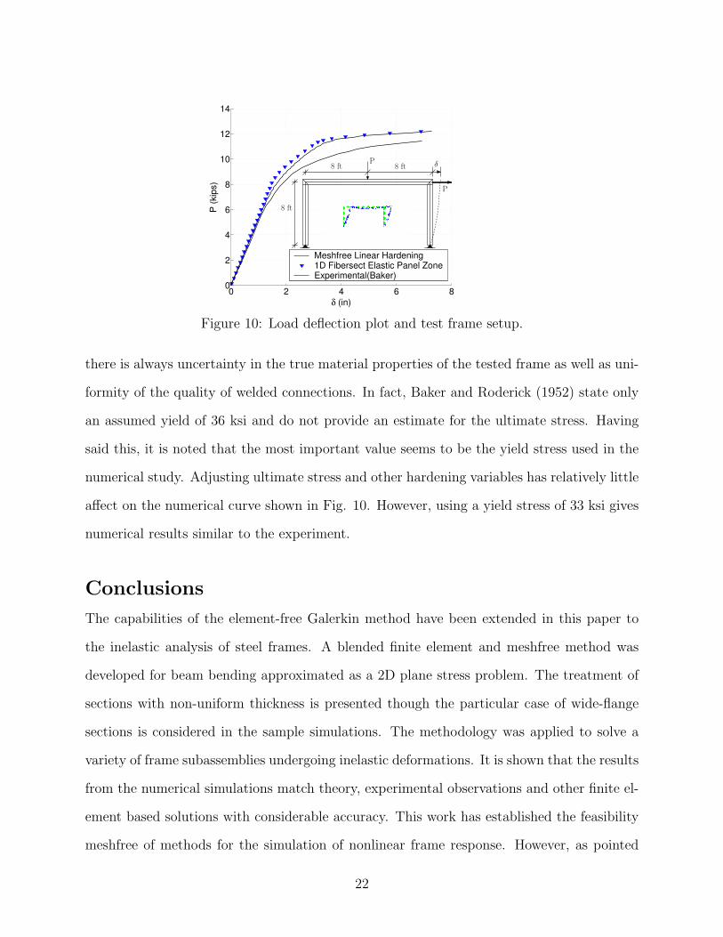
Portal Frame
Consider now the response of a portal frame loaded by equal vertical and lateral forces (see
Fig. 10). In this case an 8 inch deep I-beam with 4 inch flanges tested by Baker and Rod-
19
0 2 4 6 80
20
40
60
80
100
120
140
160
δ (in)
P (k
ips)
1D FiberSect Elasto-plastic Panel Zone1D FiberSect Elastic Panel ZoneMeshfree Linear HardeningExperimental
DeflectionGage
11 ft 3 in
11 ft 3 in
P
P
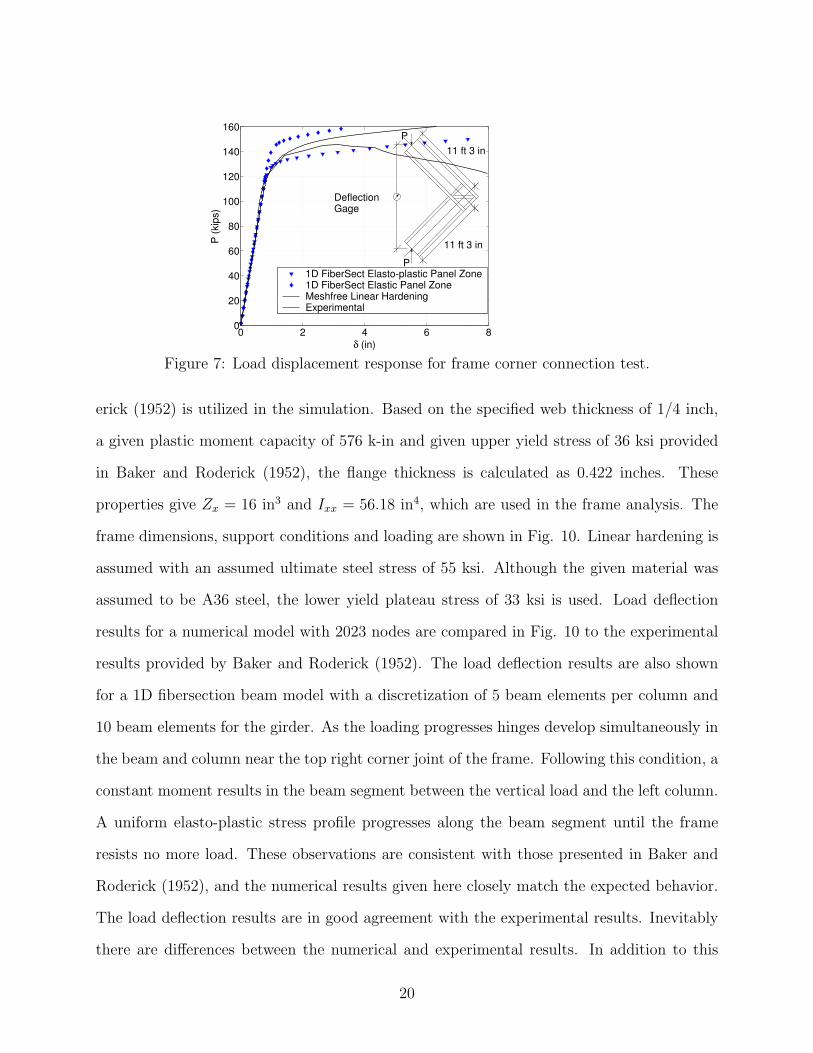
Figure 7: Load displacement response for frame corner connection test.
erick (1952) is utilized in the simulation. Based on the specified web thickness of 1/4 inch,
a given plastic moment capacity of 576 k-in and given upper yield stress of 36 ksi provided
in Baker and Roderick (1952), the flange thickness is calculated as 0.422 inches. These
properties give Zx = 16 in3 and Ixx = 56.18 in4, which are used in the frame analysis. The
frame dimensions, support conditions and loading are shown in Fig. 10. Linear hardening is
assumed with an assumed ultimate steel stress of 55 ksi. Although the given material was
assumed to be A36 steel, the lower yield plateau stress of 33 ksi is used. Load deflection
results for a numerical model with 2023 nodes are compared in Fig. 10 to the experimental
results provided by Baker and Roderick (1952). The load deflection results are also shown
for a 1D fibersection beam model with a discretization of 5 beam elements per column and
10 beam elements for the girder. As the loading progresses hinges develop simultaneously in
the beam and column near the top right corner joint of the frame. Following this condition, a
constant moment results in the beam segment between the vertical load and the left column.
A uniform elasto-plastic stress profile progresses along the beam segment until the frame
resists no more load. These observations are consistent with those presented in Baker and
Roderick (1952), and the numerical results given here closely match the expected behavior.
The load deflection results are in good agreement with the experimental results. Inevitably
there are differences between the numerical and experimental results. In addition to this
20

0 50 100 150 2000
50
100
150
200
+σxx
+σyy
+σxx
+σyy
+σxx
+σyy
-30
-20
-10
0
10
20
30
σσσσxx σσσσyy σσσσxy
(a) (b) (c)
Figure 8: Frame corner connection stresses (ksi): (a) σxx, (b) σyy and (c) σxy
0 50 100 150 2000
50
100
150
200
Deflection Magnification Factor =4
(a) (b)
Figure 9: Frame corner connection displacements: (a) without stabilization, (b) with stabi-lization
21
0 2 4 6 80
2
4
6
8
10
12
14
δ (in)
P (k
ips)
Meshfree Linear Hardening1D Fibersect Elastic Panel ZoneExperimental(Baker)
8 ft
8 ft
δP
P
8 ft
Figure 10: Load deflection plot and test frame setup.
there is always uncertainty in the true material properties of the tested frame as well as uni-
formity of the quality of welded connections. In fact, Baker and Roderick (1952) state only
an assumed yield of 36 ksi and do not provide an estimate for the ultimate stress. Having
said this, it is noted that the most important value seems to be the yield stress used in the
numerical study. Adjusting ultimate stress and other hardening variables has relatively little
affect on the numerical curve shown in Fig. 10. However, using a yield stress of 33 ksi gives
numerical results similar to the experiment.
Conclusions
The capabilities of the element-free Galerkin method have been extended in this paper to
the inelastic analysis of steel frames. A blended finite element and meshfree method was
developed for beam bending approximated as a 2D plane stress problem. The treatment of
sections with non-uniform thickness is presented though the particular case of wide-flange
sections is considered in the sample simulations. The methodology was applied to solve a
variety of frame subassemblies undergoing inelastic deformations. It is shown that the results
from the numerical simulations match theory, experimental observations and other finite el-
ement based solutions with considerable accuracy. This work has established the feasibility
meshfree of methods for the simulation of nonlinear frame response. However, as pointed
22

out in the introduction, the successful application of meshfree formulation to plane frame
analysis is only a first necessary step toward the eventual goal of extending the technology to
more complex problems. In this phase of work, only material nonlinearities in a small strain
framework were considered. Incorporation of large displacements based on a co-rotational
formulation is currently under investigation along with the use of maximum-entropy shape
functions (see Sukumar and Wright (2007)) which show promise for easier enforcement of
essential boundary conditions and numerical implementation.
Appendix A
In the present work, beams are modeled as a 2D continuum of non-constant thickness in
the direction perpendicular to the 2D plane of the domain. For example, in Fig. 11, the
Voronoi diagram of a nodal set used to discretize a plane stress cantilever beam domain
is shown. In the formulation a thickness, bf , is specified for the flanges (top and bottom
nodes) and a thickness, tw, for the intermediate nodes of the web (see also Fig. 5c). The
specified thickness covers the Voronoi cell area corresponding to each node. As a result the
grid spacing defines a grid specific tf value and one can adjust bf so the required Ixx results.
The procedure to accomplish this for an I-section follows. Given an I-beam as shown in
Web thicknes tw
specified
Flange thickness bf specified
tf
tf
Figure 11: Voronoi diagram.
Fig. 5c, the moment of inertia is written as the sum of contributions from the web and the
23

flanges. This gives
Iw =tw(d− 2tf )
3
12, (32)
If =
[2tf
(d− tf
2
)2
+t3f6
]bf = Brbf , (33)
where Br is the coefficient that multiplies bf in Eq. (33), so that
Ixx = Iw + If . (34)
Now, if the grid spacing is arbitrary then tf is set by the chosen grid. Hence, given Ixx, and
specified values of tw and d, the required thickness bf is obtained as
bf =Ixx − Iw
Br
. (35)
Equation (35) gives the necessary domain thickness perpendicular to the 2D domain at the
flanges. The specific procedure described above can be applied to any cross-section composed
of rectangular sections, and, the concept can be extended to fairly arbitrary cross-sections.
Analytical Solution and Comparison to Numerical Results for Elastic I-beam
Using the above procedure for a cantilever I-beam the results of Table 1 are obtained. The
numerical analysis and comparison to analytical results proceeds as follows. First, consider
the exact analytical elasticity solution for a cantilever beam (see Fig. 5), with transverse
shear load at its free end, as discussed in (Timoshenko and Goodier 1951), (Belytschko et al.
24

1996)
ux =−Py
6EI
[(6L− 3x)x + (2 + ν)
(y2 − D2
4
)](36a)
uy =P
6EI
[3νy2(L− x) + (4 + 5ν)
D2x
4+ (3L− x)x2
](36b)
σxx =−P (L− x)y
I(36c)
σyy = 0 (36d)
σxy =P
2I
(D2
4− y2
)(36e)
where I, which is the moment of inertia for a rectangular cross-section of unit thickness, is
given by
I =D3
12. (36f)
Even though the solution above is for a rectangular beam, it can be applied to I-beams
by simply replacing the moment of inertia term, I, in Eqs. (36a-c) by Ixx, the moment of
inertia for the I-section. Similarly, the moment of inertia of the I-beam web, Iw is used in
place of I in Eq. (36e) to determine the shear traction at the right end of the cantilever. The
tip displacement solution of the I-beam cantilever is computed from the formula provided
by Euler-Bernoulli beam theory with a shear term added, i.e.,
δtheoretical =PL3
3EIxx
+ KPL
GAw
, (37)
where K ≈ 1.0 is typical for I-beams, Aw is the I-beam web area and G is the shear modulus.
Acknowledgments
Helpful discussions with Dr. Michael Puso of Lawrence Livermore National Laboratory are
gratefully acknowledged. Research support provided by the National Science Foundation,
25

through contract grant CMMI-0626481, is also acknowledged.
References
Atluri, S. N., J. Cho, and H. Kim (1999). Analysis of thin beams, using the meshless
local Petrov-Galerkin method, with generalized moving least squares interpolations.
Computational Mechanics 2, 334–347.
Atluri, S. N. and T. Zhu (1998). A new meshless local Petrov-Galerkin (MLPG) approach
in computational mechanics. Computational Mechanics 22, 117–127.
Baker, J. F. and J. W. Roderick (1952). Tests on full-scale portal frames. Proceedings of
the Institution of Civil Engineers 1, 71–94. Part 1.
Beedle, L. S. and R. Christopher (1964). Tests of steel moment connections. AISC Engi-
neering Journal , 116–125.
Belytschko, T., Y. Krongauz, D. Organ, M. Fleming, and P. Krysl (1996). Meshless meth-
ods: an overview and recent developments. Comput. Methods Appl. Mech. Engrg. 139,
3–47.
Belytschko, T., Y. Y. Lu, and L. Gu (1994). Element-free Galerkin methods. International
Journal for Numerical Methods in Engineering 37, 229–256.
Chen, J. S., C. T. Wu, S. Yoon, and Y. You (2001). A stabilized conforming nodal inte-
gration for Galerkin meshfree methods. International Journal for Numerical Methods
in Engineering 50, 435–466.
Chen, J. S., S. Yoon, and C. T. Wu (2002). Non-linear version of stabilized conforming
nodal integration for Galerkin mesh-free methods. International Journal for Numerical
Methods in Engineering 53, 2587–2615.
Donning, B. M. and W. K. Liu (1997). Meshless methods for shear deformable beams and
plates. Comput. Methods Appl. Mech. Engrg. 152 (1–2), 47–71.
26

Fernandez-Mendez, S. and A. Huerta (2004). Imposing essential boundary conditions in
mesh-free methods. Comput. Methods Appl. Mech. Engrg. 193, 1257–1275.
Fries, T. P. and H. G. Matthies (2004). Classification and overview of meshfree meth-
ods. Technical Report Informatikbericht-Nr. 2003-03, Institute of Scientific Comput-
ing, Technical University Braunschweig, Braunschweig, Germany.
Gosz, M. R. (2006). Finite Element Method – Applications in Solids, Structures, and Heat
Transfer. Boca Raton, Florida: CRC Press.
Huerta, A. and S. Fernandez-Mendez (2004). A comparison of two formulations to blend
finite elements and mesh-free methods. Comput. Methods Appl. Mech. Engrg. 193,
1257–1275.
Johnston, B. G., C. H. Yang, and L. S. Beedle (1953). Progress report no. 8, an evaluation
of plastic analysis as applied to structural design. The Welding Journal 32, 224s–239s.
Research Supplement.
Lancaster, P. and K. Salkauskas (1992). Surfaces generated by moving least-squares meth-
ods. Math. Comput. 37, 141–158.
Li, S. and W. K. Liu (2002). Meshfree and particle methods and their applications. Appl
Mech Rev 55 (1), 1–34.
Liu, W. K., S. Jun, and Y. F. Zhang (1995). Reproducing kernel particle methods. Inter-
national Journal for Numerical Methods in Engineering 20, 1081–1106.
Mazzoni, S., F. McKenna, M. H. Scott, and G. L. Fenves (2007). OpenSees Command Lan-
guage Manual. http://opensees.berkeley.edu/index.php: The Regents of the University
of California.
Nayroles, B., G. Touzot, and P. Villon (1992). Generalizing the finite element method:
Diffuse appoximation and diffuse elements. Computational Mechanics 10, 307–318.
Phillips, A. (1956). Introduction to Plasticity. New York: The Ronald Press Co.
27

Puso, M. A., J. S. Chen, E. Zywicz, and W. Elmer (2008). Meshfree and finite element
nodal integration methods. International Journal for Numerical Methods in Engineer-
ing 74, 416–446.
Simo, J. C. and T. J. R. Hughes (1998). Computational Inelasticity. New York: Springer-
Verlag.
Simo, J. C. and R. L. Taylor (1986). Return mapping algorithm for plane stress elasto-
plasticity. International Journal for Numerical Methods in Engineering 22, 649–670.
Suetake, Y. (2002). Element-free method based on Lagrange polynomial. Journal of En-
gineering Mechanics 128 (2), 231–239.
Sukumar, N. and R. W. Wright (2007). Overview and construction of meshfree basis
functions: From moving least squares to entropy approximants. International Journal
for Numerical Methods in Engineering 70 (2), 181–205.
Timoshenko, S. P. and J. N. Goodier (1951). Theory of Elasticity (2nd ed.). New York:
McGraw-Hill.
Weitzmann, R. (2004). Limit state design of hybrid structures with meshless methods
using mathematical optimization. Bauhaus-University Weimar, Institute of Structural
Engineering. http://e-pub.uni-weimar.de/volltexte/2004/7/pdf/M_113.pdf.
Yu, T. X. and L. C. Zhang (1996). Plastic Bending - Theory and Applications. Singapore:
World Scientific Publishing.
28