MeshConnect B1010SP0 Mini Modules - SMART · CSR's µEnergy platform provides a complete Bluetooth...
16
1 This document is subject to change without notice. Document No: 0019-00-07-00-000 (Issue D) Date Published: March 29, 2016 DESCRIPTION CEL’s MeshConnect Bluetooth ® Smart Modules eliminate design risk and significantly reduce time-to-market for Bluetooth Low Energy wireless solutions, including the innovative CSRmesh™ protocol. These devices are footprint-compatible with CEL’s existing line of ZigBee and Thread-based Modules, allowing designers to easily transition between multiple wireless networking standards via drop-in compatible module hardware. KEY FEATURES • Best-in-Class RF Range of 50m to 100m • +8dBm Transmit Power • Supports CSRMesh TM • Available with Avi-on TM Software • 15 Analog/Digital I/O Pins • Supports UART, I2C & SPI APPLICATIONS • Connected Home • Building Automation • Sports & Fitness Sensors • Health Sensors • Mobile Accessories • General Bluetooth Wireless Sensor Networking BLOCK DIAGRAM Micro processor Radio CSR1010 Castellation Edge Connector 16 MHz XTAL ANT 32 kHz XTAL External EEPROM ORDERING INFORMATION Part Number Order Number Description Min/Multiple MeshConnect B1010SP0 Mini Modules B1010SP0-1-R CSR1010 IC, +8dBm Output Power, PCB Trace Antenna, 512kbit flash 600/600 B1010SP0-1C-R CSR1010 IC, +8dBm Output Power, Castellation Pin for External Antenna, 512kbit flash 600/600 B1010SP0-2-R CSR1010 IC, +8dBm Output Power, PCB Trace Antenna, 1Mbit flash 600/600 B1010SP0-2C-R CSR1010 IC, +8dBm Output Power, Castellation Pin for External Antenna, 1Mbit flash 600/600 MeshConnect ™ B1010SP0 Mini Modules B1010SP0-1x BLE Transceiver Based Modules Integrated Transceiver Modules for Bluetooth ® Smart Applications
Transcript of MeshConnect B1010SP0 Mini Modules - SMART · CSR's µEnergy platform provides a complete Bluetooth...

1 This document is subject to change without notice. Document No: 0019-00-07-00-000 (Issue D) Date Published: March 29, 2016
DESCRIPTION CEL’s MeshConnect Bluetooth® Smart Modules eliminate design risk and significantly reduce time-to-market for Bluetooth Low Energy wireless solutions, including the innovative CSRmesh™ protocol. These devices are footprint-compatible with CEL’s existing line of ZigBee and Thread-based Modules, allowing designers to easily transition between multiple wireless networking standards via drop-in compatible module hardware.
KEY FEATURES • Best-in-Class RF Range of 50m to 100m • +8dBm Transmit Power • Supports CSRMeshTM • Available with Avi-onTM Software • 15 Analog/Digital I/O Pins • Supports UART, I2C & SPI APPLICATIONS • Connected Home • Building Automation • Sports & Fitness Sensors • Health Sensors • Mobile Accessories • General Bluetooth Wireless Sensor Networking
BLOCK DIAGRAM
Micro processor Radio
CSR1010
Cas
tella
tion
Edge
Con
nect
or
16 MHzXTAL
ANT
32 kHzXTALExternal
EEPROM
ORDERING INFORMATION
Part Number Order Number Description Min/Multiple
MeshConnect B1010SP0 Mini
Modules
B1010SP0-1-R CSR1010 IC, +8dBm Output Power, PCB Trace Antenna, 512kbit flash 600/600
B1010SP0-1C-R CSR1010 IC, +8dBm Output Power, Castellation Pin for External Antenna, 512kbit flash
600/600
B1010SP0-2-R CSR1010 IC, +8dBm Output Power, PCB Trace Antenna, 1Mbit flash 600/600
B1010SP0-2C-R CSR1010 IC, +8dBm Output Power, Castellation Pin for External Antenna, 1Mbit flash
600/600
MeshConnect™ B1010SP0 Mini Modules B1010SP0-1x
BLE Transceiver Based Modules
Integrated Transceiver Modules for Bluetooth® Smart Applications

B1010SP0 Mini Modules
2 This document is subject to change without notice. Document No: 0019-00-07-00-000 (Issue D) Date Published: March 29, 2016
DEVELOPMENT KIT
MeshConnect µEnergy Starter Development Kit CSR's µEnergy platform provides a complete Bluetooth qualified solution for products using the Bluetooth Low Energy standard. CEL's µEnergy Starter Development Kit is a simple yet comprehensive way for designers to develop Bluetooth Smart applications using CSR's µEnergy solution. Each kit contains:
• Evaluation board with B1010SP0 Mini Module • CSR µEnergy Platform Software
o Software Development Kit (SDK) application examples and development tools
o xIDE for µEnergy (includes compiler) o Production test and configuration tools
• Mini-USB Cable • Setup & Quick Start Guides
Visit http://meshconnect.cel.com/B1010 for more information. KIT ORDERING INFORMATION
Kit Family Order Number Description Min/Multiple
MeshConnect µEnergy Starter Development Kit
B1010SP0-EVB-1 µEnergy Starter Development Kit, with license for CSR µEnergy SDK, 512kbit flash memory module
1/1
B1010SP0-EVB-2 µEnergy Starter Development Kit, with license for CSR µEnergy SDK, 1Mbit flash memory module
1/1
B1010SP0 Mini Modules
3 This document is subject to change without notice. Document No: 0019-00-07-00-000 (Issue D) Date Published: March 29, 2016
TABLE OF CONTENTS DESCRIPTION ...................................................................................................................................... 1
KEY FEATURES ..................................................................................................................................... 1
APPLICATIONS ..................................................................................................................................... 1
BLOCK DIAGRAM................................................................................................................................. 1
ORDERING INFORMATION ................................................................................................................... 1
DEVELOPMENT KIT .............................................................................................................................. 2
KIT ORDERING INFORMATION ............................................................................................................. 2
TABLE OF CONTENTS ........................................................................................................................... 3
TRANSCEIVER IC .................................................................................................................................. 4
ANTENNA ............................................................................................................................................ 4
EXTERNAL EEPROM ............................................................................................................................. 4
SOFTWARE / FIRMWARE ..................................................................................................................... 5
CRYSTAL FREQUENCY TRIM AND BLUETOOTH DEVICE ADDRESS........................................................... 5
ABSOLUTE MAXIMUM RATINGS .......................................................................................................... 7
RECOMMENDED OPERATING CONDITIONS .......................................................................................... 7
DC CHARACTERISTICS .......................................................................................................................... 7
RF CHARACTERISTICS ........................................................................................................................... 8
I/O PIN ASSIGNMENTS ........................................................................................................................ 9
ZICM35x ZIGBEE/THREAD MODULE COMPATIBILITY ............................................................................ 9
ERRATA ..............................................................................................................................................10
MODULE DIMENSIONS .......................................................................................................................10
MODULE LAND FOOTPRINT ................................................................................................................11
AGENCY CERTIFICATIONS (PCB ANTENNA ONLY) .................................................................................14
SHIPMENT, HANDLING AND STORAGE ................................................................................................15
QUALITY ............................................................................................................................................15
REFERENCES .......................................................................................................................................16
REVISION HISTORY .............................................................................................................................16
DISCLAIMER .......................................................................................................................................16
B1010SP0 Mini Modules
4 This document is subject to change without notice. Document No: 0019-00-07-00-000 (Issue D) Date Published: March 29, 2016
TRANSCEIVER IC CEL’s MeshConnect B1010SP0 Mini Module, utilizing the CSR1010 transceiver IC, is a single-mode Bluetooth Low Energy (BLE) device that is part of CSR's µEnergy platform. This transceiver incorporates a baseband modem, RF circuitry, and 16-bit XAP microprocessor. Together with CSR's qualified Bluetooth v4.x specification stack, it is an excellent low cost, low power consumption and high performance solution ideally suited for all BLE applications. For more information about the CSR1010 IC, please visit www.csr.com. ANTENNA CEL’s B1010SP0 Mini Modules include an integrated Printed Circuit Board (PCB) trace antenna. An optional configuration which uses a castellation pin on the module allows the user to connect an external antenna. The B1010SP0 has been certified with the PCB trace antenna only. The PCB antenna employs a topology that is compact and highly efficient. To maximize range, an adequate ground plane must be provided on the host PCB. Correctly positioned, the ground plane on the host PCB will contribute significantly to the antenna performance (it should not be directly under the module PCB antenna). The position of the module on the host board and overall design of the product enclosure contribute to antenna performance. Poor design affects radiation patterns and can result in reflection, diffraction and/or scattering of the transmitted signal. For optimum antenna performance, the MeshConnect Mini Modules should be mounted with the PCB trace antenna overhanging the edge of the host board. To further improve performance, a ground plane may be placed on the host board under the module; up to the antenna (a minimum of 1.5" x 1.5" is recommended). The installation of an uninterrupted ground plane on a layer directly beneath the module will also allow you to run traces under this layer. CEL can provide assistance with your PCB layout. The following are some design guidelines to help ensure antenna performance:
• Never place the ground plane or route copper traces directly underneath the antenna portion of the module • Never place the antenna close to metallic objects • In the overall design, ensure that wiring and other components are not placed near the antenna • Do not place the antenna in a metallic or metalized plastic enclosure • Keep plastic enclosures 1cm or more away from the antenna in any direction
Under Industry Canada regulations, this radio transmitter may only operate using an antenna of a type and maximum (or lesser) gain approved for the transmitter by Industry Canada. To reduce potential radio interference to other users, the antenna type and its gain should be so chosen that the equivalent isotropically radiated power (e.i.r.p.) is not more than that necessary for successful communication. Conformément à la réglementation d'Industrie Canada, le présent émetteur radio peut fonctionner avec une antenne d'un type et d'un gain maximal (ou inférieur) approuvé pour l'émetteur par Industrie Canada. Dans le but de réduire les risques de brouillage radioélectrique à l'intention des autres utilisateurs, il faut choisir le type d'antenne et son gain de sorte que la puissance isotrope rayonnée équivalente (p.i.r.e.) ne dépasse pas l'intensité nécessaire à l'établissement d'une communication satisfaisante. EXTERNAL EEPROM The B1010SP0 Mini Module incorporates an additional 512kbit or 1Mbit external EEPROM for storing program code and Over-The-Air code updates. The EEPROM is connected to the master I2C interface using I2C_SCL, I2C_SDA, and PIO[2] as detailed in the CSR1010 reference design. The instruction set for the 512kbit EEPROM is similar to the Fudan FM24C512D. See the Fudan Microelectronics Group website for more details. The instruction set for the Atmel AT24CM01-SSHD-T 1Mbit EEPROM is available on website.
B1010SP0 Mini Modules
5 This document is subject to change without notice. Document No: 0019-00-07-00-000 (Issue D) Date Published: March 29, 2016
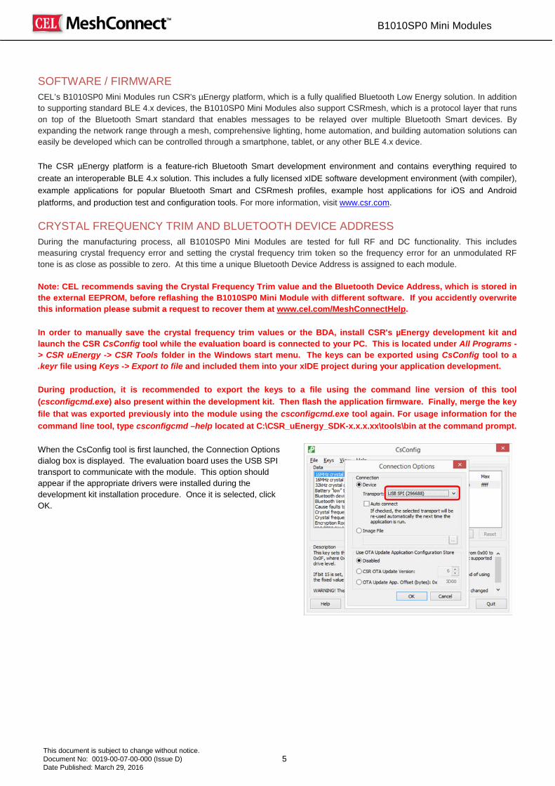
SOFTWARE / FIRMWARE CEL’s B1010SP0 Mini Modules run CSR's µEnergy platform, which is a fully qualified Bluetooth Low Energy solution. In addition to supporting standard BLE 4.x devices, the B1010SP0 Mini Modules also support CSRmesh, which is a protocol layer that runs on top of the Bluetooth Smart standard that enables messages to be relayed over multiple Bluetooth Smart devices. By expanding the network range through a mesh, comprehensive lighting, home automation, and building automation solutions can easily be developed which can be controlled through a smartphone, tablet, or any other BLE 4.x device. The CSR µEnergy platform is a feature-rich Bluetooth Smart development environment and contains everything required to create an interoperable BLE 4.x solution. This includes a fully licensed xIDE software development environment (with compiler), example applications for popular Bluetooth Smart and CSRmesh profiles, example host applications for iOS and Android platforms, and production test and configuration tools. For more information, visit www.csr.com. CRYSTAL FREQUENCY TRIM AND BLUETOOTH DEVICE ADDRESS During the manufacturing process, all B1010SP0 Mini Modules are tested for full RF and DC functionality. This includes measuring crystal frequency error and setting the crystal frequency trim token so the frequency error for an unmodulated RF tone is as close as possible to zero. At this time a unique Bluetooth Device Address is assigned to each module. Note: CEL recommends saving the Crystal Frequency Trim value and the Bluetooth Device Address, which is stored in the external EEPROM, before reflashing the B1010SP0 Mini Module with different software. If you accidently overwrite this information please submit a request to recover them at www.cel.com/MeshConnectHelp. In order to manually save the crystal frequency trim values or the BDA, install CSR's µEnergy development kit and launch the CSR CsConfig tool while the evaluation board is connected to your PC. This is located under All Programs -> CSR uEnergy -> CSR Tools folder in the Windows start menu. The keys can be exported using CsConfig tool to a .keyr file using Keys -> Export to file and included them into your xIDE project during your application development. During production, it is recommended to export the keys to a file using the command line version of this tool (csconfigcmd.exe) also present within the development kit. Then flash the application firmware. Finally, merge the key file that was exported previously into the module using the csconfigcmd.exe tool again. For usage information for the command line tool, type csconfigcmd –help located at C:\CSR_uEnergy_SDK-x.x.x.xx\tools\bin at the command prompt. When the CsConfig tool is first launched, the Connection Options dialog box is displayed. The evaluation board uses the USB SPI transport to communicate with the module. This option should appear if the appropriate drivers were installed during the development kit installation procedure. Once it is selected, click OK.
B1010SP0 Mini Modules
6 This document is subject to change without notice. Document No: 0019-00-07-00-000 (Issue D) Date Published: March 29, 2016
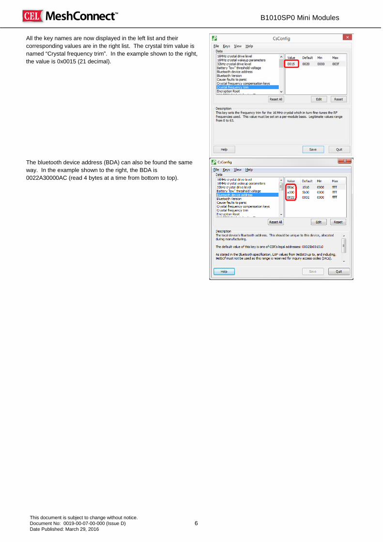
All the key names are now displayed in the left list and their corresponding values are in the right list. The crystal trim value is named “Crystal frequency trim”. In the example shown to the right, the value is 0x0015 (21 decimal).
The bluetooth device address (BDA) can also be found the same way. In the example shown to the right, the BDA is 0022A30000AC (read 4 bytes at a time from bottom to top).

B1010SP0 Mini Modules
7 This document is subject to change without notice. Document No: 0019-00-07-00-000 (Issue D) Date Published: March 29, 2016
ABSOLUTE MAXIMUM RATINGS
Description Min Max Unit
Storage temperature range -40 85 ⁰C
Power supply voltage (VDD) 1.8 4.4 V
I/O supply voltage -0.4 4.4 V
Other terminal voltage* VSS - 0.4 VDD + 0.4 V
* VDD = Terminal Supply Domain
RECOMMENDED OPERATING CONDITIONS
Description Min Typ Max Unit
Operating temperature range -30 - 85 ⁰C
Power supply voltage (VDD) 1.8 - 3.6 V
DC CHARACTERISTICS (@25⁰C unless otherwise specified)
Description Conditions Min Typ Max Unit
Transmitter Current Draw, max output power
@ 2.7V - 35 - mA
@ 1.8V - 54 - mA
@ 3.6V - 25 - mA
Transmitter Current Draw @ 0dBm
@ 2.7V - 23 - mA
@ 1.8V - 39 - mA
@ 3.6V - 17 - mA
Receiver Current Draw
@ 2.7V - 24 - mA
@ 1.8V - 39 - mA
@ 3.6V - 17 - mA
Sleep mode current (Dormant mode) @ 3.3V - 0.9 - µA

B1010SP0 Mini Modules
8 This document is subject to change without notice. Document No: 0019-00-07-00-000 (Issue D) Date Published: March 29, 2016
RF CHARACTERISTICS (@25⁰C unless otherwise specified)
Path Description Conditions Min Typ Max Unit
Operating Frequency 2402 2480 MHz
TX
Maximum output power - 8 - dBm
2nd Harmonic - - 54 dBuV
3rd Harmonic - - 54 dBuV
In-band emissions
F = Fo ± 2MHz - -38 - dBm
F = Fo ± 3MHz - -38 - dBm
F = Fo ± > 3MHz - -38 - dBm
Modulation delta F1 average 225 255 275 kHz
Modulation delta F1 / F2 0.8 - - -
Modulation delta F2 max - 100 - %
Frequency accuracy -100 25 100 kHz
Frequency offset -100 25 100 kHz
Maximum Drift Rate (kHz/50µs) -20 8 20 kHz / 50uS
RX
Receiver Sensitivity -94 dBm
Receiver Sensitivity (with dirty transmitter) -93 dBm
Maximum received signal at 30.8% PER -10 ≥ -10 dBm

B1010SP0 Mini Modules
9 This document is subject to change without notice. Document No: 0019-00-07-00-000 (Issue D) Date Published: March 29, 2016
I/O PIN ASSIGNMENTS Refer to the CSR1010 datasheet for pin functionality details.
Module Pin Number
CSR1010 IC Pin Number Pin Name Notes
1, 2, 12, 31, 33 33 to 48 GND
3, 4, 5, 6, 16, 17, 18,
26 NC NC
7 4 WAKE 8 23 PIO[9] 9 24 PIO[10]
10 16 PIO[3] 11 29 I2C_SDA Connects internally to SDA on the onboard serial flash. 13 1, 21, 32 VDD Input power to the module.
14 28 I2C_SCL Connects internally to SCL on the onboard serial flash. 15 17 PIO[4] 19 14 PIO[0] / UART_TX Programmable I/O line or UART TX 20 15 PIO[1] / UART_RX Programmable I/O line or UART RX 21 26 SPI_PIO# Selects SPI debug on PIO[8:5]
22 19 PIO[6] Programmable I/O line or debug SPI chip select
23 20 PIO[7] Programmable I/O line or debug SPI MOSI 24 22 PIO[8] Programmable I/O line or debug SPI MISO 25 13 AIO[0] 27 18 PIO[5] Programmable I/O line or debug SPI CLK 28 12 AIO[1] 29 25 PIO[11] 30 11 AIO[2] 32 NC RF OUT Castellation Pin for External Antenna
ZICM35x ZIGBEE/THREAD MODULE COMPATIBILITY The geometry of the land pattern and location of the RF castellation is identical to the ZICM35x family of ZigBee/Thread modules. The compatible digital and analog I/O are described below:
Description ZICM35x B1010SP0 Notes
Serial Controller 1 UART / SPI / I2C UART / SPI / I2C Castellation pins 8,9,19,20
Serial Controller 2 SPI/I2C I2C Castellation pins 10,11,14,15
GPIO PC2 PIO[6] GPIO PC3 PIO[7] GPIO PC4 PIO[8] GPIO PC0 PIO[5] GPIO PB6 PIO[11] GPIO PA7 WAKE This line can only be used to wake the
B1010SP0 from sleep.
Programming JTCK SPI_PIO# Driving this line high on B1010SP0 converts PIO[5,6,7,8] to the SPI programming port.
ADC PB0, PB5, PB7 AIO[0], AIO[2], AIO[1]
B1010SP0 lines can also be configured as a DAC.
B1010SP0 Mini Modules
10 This document is subject to change without notice. Document No: 0019-00-07-00-000 (Issue D) Date Published: March 29, 2016
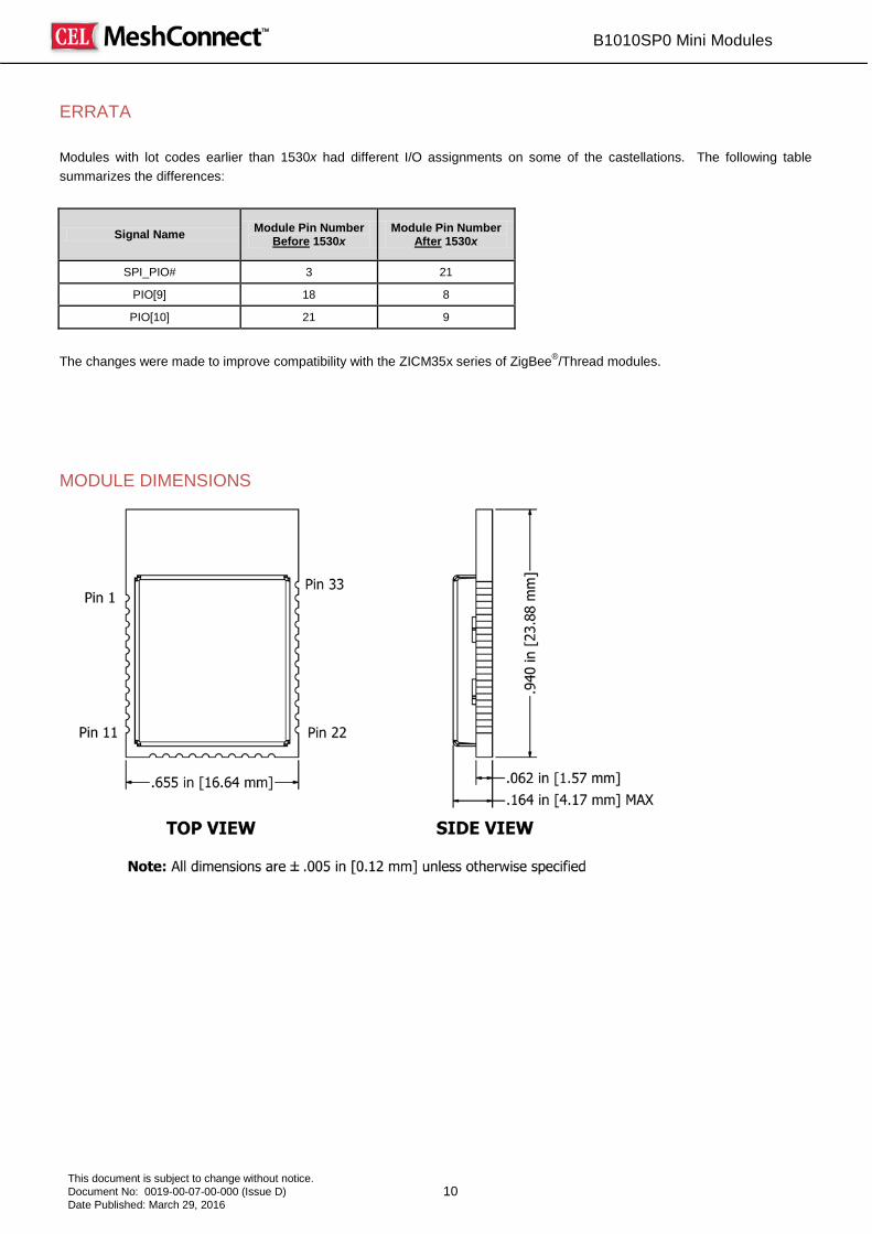
ERRATA
Modules with lot codes earlier than 1530x had different I/O assignments on some of the castellations. The following table summarizes the differences:
Signal Name Module Pin Number Before 1530x
Module Pin Number After 1530x
SPI_PIO# 3 21
PIO[9] 18 8
PIO[10] 21 9
The changes were made to improve compatibility with the ZICM35x series of ZigBee®/Thread modules. MODULE DIMENSIONS

B1010SP0 Mini Modules
11 This document is subject to change without notice. Document No: 0019-00-07-00-000 (Issue D) Date Published: March 29, 2016
MODULE LAND FOOTPRINT Dimensions are shown in inches, with millimeter conversion in brackets
Note: Refer to the Antenna section in this document for layout recommendations which will yield optimal antenna performance. PROCESSING
Recommended Reflow Profile Parameter Values
Ramp Up Rate (from Tsoakmax to Tpeak) 3º/sec max
Minimum Soak Temperature 150ºC
Maximum Soak Temperature 200ºC
Soak Time 60-120 sec
TLiquidus 217ºC
Time above TL 60-150 sec
Tpeak 250ºC
Time within 5º of Tpeak 20-30 sec
Time from 25º to Tpeak 8 min max
Ramp Down Rate 6ºC/sec max
B1010SP0 Mini Modules
12 This document is subject to change without notice. Document No: 0019-00-07-00-000 (Issue D) Date Published: March 29, 2016
Pb-Free Solder Paste Use of “No Clean” soldering paste is strongly recommended, as it does not require cleaning after the soldering process.
Note: The quality of solder joints on the castellations ("half vias") where they contact the host board should meet the appropriate IPC Specification. See the Castellated Terminations Section in the latest IPC-A-610 Acceptability of Electronic Assemblies document.
Cleaning In general, cleaning the populated module is strongly discouraged. Residuals under the module cannot be easily removed with any cleaning process. • Cleaning with water can lead to capillary effects where water is absorbed into the gap between the host
board and the module. The combination of soldering flux residuals and encapsulated water could lead to short circuits between neighboring pads. Water could also damage any stickers or labels.
• Cleaning with alcohol or a similar organic solvent will likely flood soldering flux residuals into the two housings, which is not accessible for post-washing inspection. The solvent could also damage any stickers or labels. • Ultrasonic cleaning could damage the module permanently. The best approach is to consider using a “No Clean” solder paste and eliminate the post-soldering cleaning step.
Optical Inspection After soldering the module to the host board, consider optical inspection to check the following: • Proper alignment and centering of the module over the pads • Proper solder joints on all pads • Excessive solder or contacts to neighboring pads or vias
Repeating Reflow Soldering Only a single reflow soldering process is encouraged for host boards.
Wave Soldering If a wave soldering process is required on the host boards due to the presence of leaded components, only a single wave soldering process is encouraged.
Hand Soldering Hand soldering is possible. When using a soldering iron, follow IPC recommendations.(reference document IPC-7711).
Rework The MeshConnect Module can be unsoldered from the host board. Use of a hot air rework tool should be programmable and the solder joint and module should not exceed the maximum peak reflow temperature of 250ºC.

B1010SP0 Mini Modules
13 This document is subject to change without notice. Document No: 0019-00-07-00-000 (Issue D) Date Published: March 29, 2016
Caution If temperature ramps exceed the reflow temperature profile, module and component damage may occur due to thermal shock. Avoid overheating.
Warning Never attempt a rework on the module itself (i.e., replacing individual components); such actions will terminate warranty coverage.
Additional Grounding Attempts to improve the module or the system grounding by soldering braids, wires or cables onto the module RF shield cover is done at the customer's own risk. The ground pins at the module perimeter should be sufficient for optimum immunity to external RF interference.
B1010SP0 Mini Modules
14 This document is subject to change without notice. Document No: 0019-00-07-00-000 (Issue D) Date Published: March 29, 2016
AGENCY CERTIFICATIONS (PCB ANTENNA ONLY) The following certifications are in effect:
• B1010SP0: FCC and IC
FCC Compliance Statement Part 15.19, Section 7.15 of RSS-GEN This device complies with Part 15 of the FCC Rules and with Industry Canada license-exempt RSS Standards. Operation is subject to the following two conditions: 1. This device may not cause harmful interference. 2. This device must accept any interference received, including interference that may cause undesired operation. Le présent appareil est conforme aux CNR d'Industrie Canada applicables aux appareils radio exempts de licence. L'exploitation est autorisée aux deux conditions suivantes: 1. l'appareil ne doit pas produire de brouillage, et 2. l'utilisateur de l'appareil doit accepter tout brouillage radioélectrique subi, même si le brouillage est susceptible d'en compromettre le fonctionnement.
Warning (Part 15.21) Changes or modifications not expressly approved by CEL could void the user's authority to operate the equipment.
20 cm Separation Distance To comply with FCC/IC RF exposure limits for general population/uncontrolled exposure, the antenna(s) used for this transmitter must be installed to provide a separation distance of at least 20 cm from all persons and must not be co-located or operating in conjunction with any other antenna or transmitter.
OEM Responsibility to the FCC and IC Rules and Regulations The MeshConnect Mini Module has been certified per FCC Part 15 Rules and to Industry Canada license-exempt RSS Standards for integration into products without further testing or certification. To fulfill the FCC and IC Certification requirements, the OEM of the MeshConnect Module must ensure that the information provided on the MeshConnect label is placed on the outside of the final product. The MeshConnect Mini Module is labeled with its own FCC ID Number and IC ID Number. If the FCC ID and the IC ID are not visible when the module is installed inside another device, then the outside of the device into which the module is installed must also display a label referring to the enclosed module. The exterior label can use wording such as the following: “Contains Transmitter Module FCC ID: W7Z-B1010SP0” or “Contains FCC ID: W7Z-B1010SP0” “Contains Transmitter Module IC: 8254A-B1010SP0" or "Contains IC: 8254A-B1010SP0” The OEM of the MeshConnect Mini Module may only use the approved antenna (PCB trace antenna) that has been certified with this module. The OEM of the MeshConnect Mini Module must test their final product configuration to comply with Unintentional Radiator Limits before declaring FCC Compliance per Part 15 of the FCC Rules.
IC Certification — Industry Canada Statement The term "IC" before the certification/registration number only signifies that the Industry Canada technical specifications were met.
Certification IC - Déclaration d'Industrie Canada Le terme "IC" devant le numéro de certification/d'enregistrement signifie seulement que les spécifications techniques Industrie Canada ont été respectées.
Section 14 of RSS-210 The installer of this radio equipment must ensure that the antenna is located or pointed such that it does not emit RF field in excess of Health Canada limits for the general population. Consult Safety Code 6, obtainable from Health Canada's website: http://www.hc-sc.gc.ca/ewh-semt/pubs/radiation/99ehd-dhm237/index-eng.php

B1010SP0 Mini Modules
15 This document is subject to change without notice. Document No: 0019-00-07-00-000 (Issue D) Date Published: March 29, 2016
L'article 14 du CNR-210 Le programme d'installation de cet équipement radio doit s'assurer que l'antenne est située ou orientée de telle sorte qu'il ne pas émettre de champ RF au-delà des limites de Santé Canada pour la population générale. Consulter le Code de sécurité 6, disponible sur le site Web de Santé Canada: http://www.hc-sc.gc.ca/ewh-semt/pubs/radiation/99ehd-dhm237/index-eng.php
SHIPMENT, HANDLING AND STORAGE
Shipment The MeshConnect Modules are delivered in tape and reel. The reel diameter is 12.992" (330mm) and contains 600 modules.
Handling The MeshConnect Modules are designed and packaged to be processed in an automated assembly line.
Warning The MeshConnect Modules contain highly sensitive electronic circuitry. Handling without proper ESD protection may destroy or damage the module permanently.
Warning The MeshConnect Modules are moisture-sensitive devices. Appropriate handling instructions and precautions are summarized in J-STD-033. Read carefully to prevent permanent damage due to moisture intake.
Moisture Sensitivity Level (MSL) MSL 3, per J-STD-033
Storage Storage/shelf life in sealed bags is 12 months at <40°C and <90% relative humidity. QUALITY CEL Modules offer the highest quality at competitive prices. Our modules are manufactured in compliance with the IPC-A-610 specification, Class II. Our modules go through JESD22 qualification processes which includes high temperature operating life tests, mechanical shock, temperature cycling, humidity and reflow testing. CEL conducts RF and DC factory testing on 100% of all production parts. CEL builds the quality into our products, giving our customers confidence when integrating our products into their systems.
B1010SP0 Mini Modules
16 This document is subject to change without notice. Document No: 0019-00-07-00-000 (Issue D) Date Published: March 29, 2016
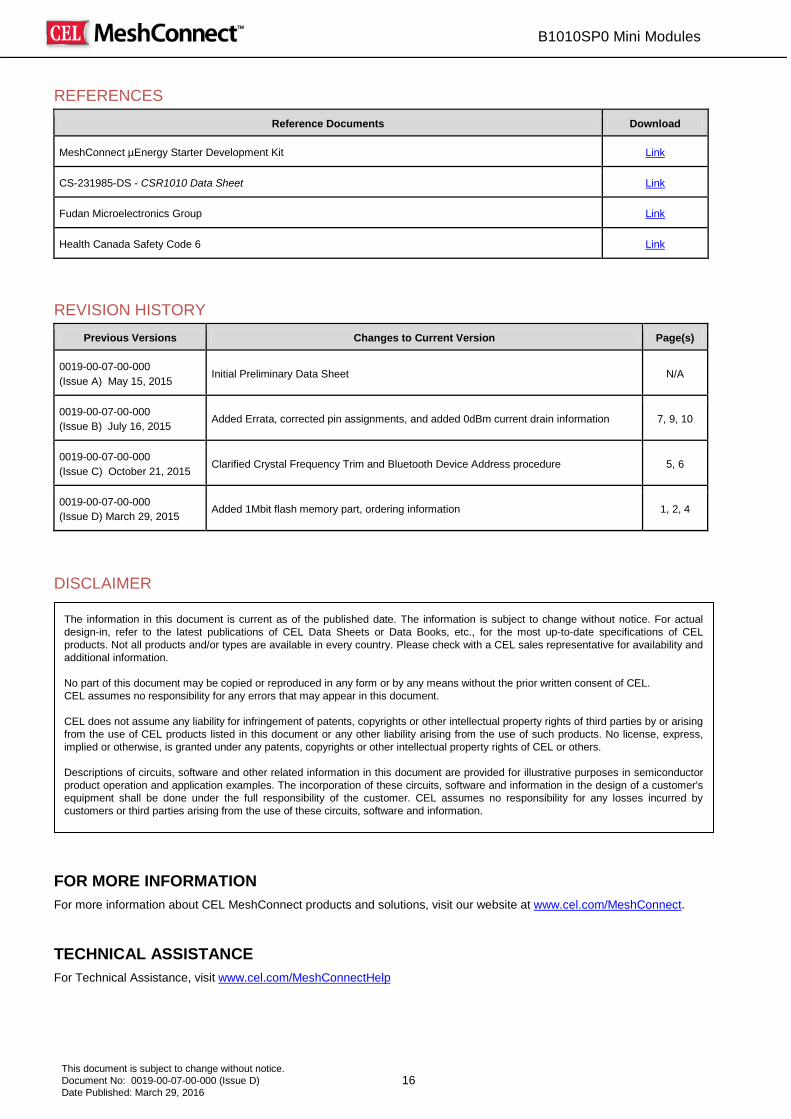
REFERENCES
Reference Documents Download
MeshConnect µEnergy Starter Development Kit Link
CS-231985-DS - CSR1010 Data Sheet Link
Fudan Microelectronics Group Link
Health Canada Safety Code 6 Link
REVISION HISTORY
Previous Versions Changes to Current Version Page(s)
0019-00-07-00-000 (Issue A) May 15, 2015
Initial Preliminary Data Sheet N/A
0019-00-07-00-000 (Issue B) July 16, 2015
Added Errata, corrected pin assignments, and added 0dBm current drain information 7, 9, 10
0019-00-07-00-000 (Issue C) October 21, 2015
Clarified Crystal Frequency Trim and Bluetooth Device Address procedure 5, 6
0019-00-07-00-000 (Issue D) March 29, 2015
Added 1Mbit flash memory part, ordering information 1, 2, 4
DISCLAIMER
FOR MORE INFORMATION For more information about CEL MeshConnect products and solutions, visit our website at www.cel.com/MeshConnect.
TECHNICAL ASSISTANCE For Technical Assistance, visit www.cel.com/MeshConnectHelp
The information in this document is current as of the published date. The information is subject to change without notice. For actual design-in, refer to the latest publications of CEL Data Sheets or Data Books, etc., for the most up-to-date specifications of CEL products. Not all products and/or types are available in every country. Please check with a CEL sales representative for availability and additional information. No part of this document may be copied or reproduced in any form or by any means without the prior written consent of CEL. CEL assumes no responsibility for any errors that may appear in this document. CEL does not assume any liability for infringement of patents, copyrights or other intellectual property rights of third parties by or arising from the use of CEL products listed in this document or any other liability arising from the use of such products. No license, express, implied or otherwise, is granted under any patents, copyrights or other intellectual property rights of CEL or others. Descriptions of circuits, software and other related information in this document are provided for illustrative purposes in semiconductor product operation and application examples. The incorporation of these circuits, software and information in the design of a customer’s equipment shall be done under the full responsibility of the customer. CEL assumes no responsibility for any losses incurred by customers or third parties arising from the use of these circuits, software and information.