
MERLIN - · MERLIN® communications system, Model 820. ... If you have a Feature Package, refer to...
40
AT&T MERLIN ® COMMUNICATIONS SYSTEM INSTALLATION GUIDE: MODEL 820
Transcript of MERLIN - · MERLIN® communications system, Model 820. ... If you have a Feature Package, refer to...

AT&T
MERLIN®
COMMUNICATIONS SYSTEM
INSTALLATION GUIDE:MODEL 820

Table of ContentsPage
Introduction
Getting Started
Preparing the Network InterfaceExtend the Network Interface to the Jack FieldTest the Outside Lines
Installing the Control UnitPosition the Control UnitInsert the Modules and CartridgesConnect the Control Unit to the AC OutletConnect the Outside Lines to the Control Unit
Voice Terminal WiringJack Field ConnectionDirect Connection
Connecting the Voice TerminalsPrepare the Voice TerminalsConnect Each Voice Terminal to the SystemTest Each Voice Terminal for a Dial ToneLabel the Voice Terminals with Intercom Numbers
Installing AccessoriesCartridgesAccessory EquipmentPower Accessories
System TestsTest the Voice Terminal Jacks for a Dial TonePlace an Outside CallPlace an Intercom CallTest Each Line Number
What’s Next?
System ChangesAdding an Outside LineAdding a Voice TerminalMoving a Voice TerminalChanging Touch-Tone/Rotary Service
TroubleshootingTroubleshooting TableGeneral Test
Appendix A: Interference Information
Appendix B: FCC Registration and Repair Information
Index
2
3
7 9
13
1414151617
181920
2121222525
26262626
2727282929
30
3131313232
333336
37
37
38
IntroductionThis installation guide tells you how to install and test yourMERLIN® communications system, Model 820. It leads you step by stepthrough system installation, from a pre-installation checklist to system tests.You should perform the steps in the order in which they are presented becausemany of the earlier steps prepare the system for the later steps.
When you complete the steps in this guide, you will be ready to customize thesystem to meet the needs of your business. If you have a Feature Package, referto the administration manual that comes with it for administration and program-ming instructions. Your system may not be fully operable until you have pro-grammed and administered it.
This guide consists of the following sections:
●
●
●
●
●
●
●
●
●
●
Getting Started tells you how to prepare for system installation.Preparing the Network Interface shows you how to prepare the connec-tion to your outside telephone lines.Installing the Control Unit explains how to set up and connect thesystem’s control unit.Voice Terminal Wiring tells you how to install the wiring for your voice ter-minals (MERLIN system telephones).Connecting the Voice Terminals tells you how to connect your voice ter-minals to the system and test them.Installing Accessories describes some of the accessories that you maywant to add to your system and explains when it may be appropriate toinstall these accessories.System Tests provides tests to make sure you’ve installed your systemproperly.What’s Next? refers you to documents that describe how to customize anduse your system.System Changes describes how to rearrange or alter your system onceit is in place.Troubleshooting isolates and identifies specific problems that could ariseduring system installation, and suggests solutions to basic problems.
The steps in this guide are numbered in order of performance. To visualize astep as it is described, refer to the pictures accompanying the text. The numbersin the drawings correspond to the step numbers in the text.
2
Getting StartedThis guide assumes the tasks on the following list have been completed. Reviewthe list carefully. If you have not completed the tasks on the list, you should doso now.
●
●
Check the items in your shipment against your copy of the order form.
Make sure the items and quantities agree. Save the instructions that comewith each component, and also keep the packing boxes just in case youhave to return components under warranty.
Get acquainted with the system environment.
Review the planning sheets you drew up when you ordered the system.Confirm the voice terminal and control unit locations, and make sure thecontrol unit location meets the following environmental standards:
— Operating temperatures: 40 to 104°F (4 to 40°C).— Humidity: not to exceed 80%.— Ventilation: Leave 6 inches of space above and to the sides of the
control unit. Keep the control unit away from sources of extreme heat(furnaces, heaters, attics, or direct sunlight). Do not stack multiplecontrol units in rooms that are not air-conditioned; install them sideby side at least 6 inches apart.
— Airborne contamination: Do not expose the control unit to moisture,corrosive gases, dust, chemicals, or similar substances.
If the control unit location does not meet these standards, your warrantymay become void.
3
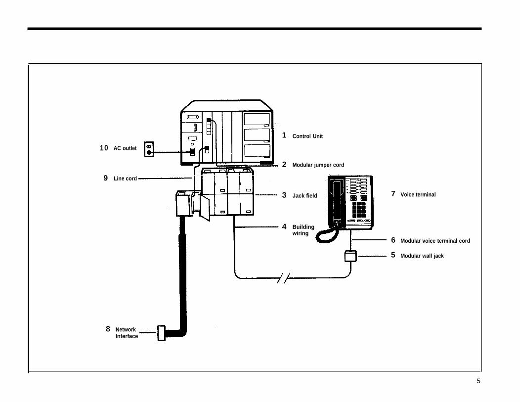
● Become familiar with the MERLIN system.Review the drawing of a simple MERLIN system configuration, oppositepage, and note how components are related to one another.
●
1
2
3
4
5
6
7
8
9
10NOTE:
The control unit and the cartridges and modules it contains pro-vide the power and the intelligence for all voice terminals andaccessories.Modular jumper cords connect the control unit to jacks in the jackfield.
The jack field serve as an interface between the control unit andthe building wiring.
Building wiring ties the whole system together, connecting thevoice terminal locations to the control unit location.
Modular wall jacks connect the voice terminals to the buildingwiring.
Modular voice terminal cords connect the voice terminals to themodular wall jacks.
Voice terminals provide telephone functions and access to theadvanced features in the control unit.
The network interface, shown here extended to the jack field, pro-vides the connection to the local telephone company lines.
Line cords connect the control unit to the network interface or, asshown, to the jacks in the jack field for the outside telephone lines.
The ac outlet is the electrical power source for the control unit.Modular jumper cords are identical to modular voice terminal
Make sure your system wiring is in place.You must have wiring that connects your voice terminal locations to yourcontrol unit location. If your voice terminal locations are close enough toyour control unit to make direct connection practical, you are probably plan-ning to connect your voice terminals directly to the control unit with modularvoice terminal cords and, if necessary, modular voice terminal extensioncords. If you are planning to connect your voice terminals directly to thecontrol unit, this guide tells you how to do so at the appropriate place inthe installation sequence.If conditions at your business make direct connections between your voiceterminal locations and your control unit location impractical, then you haveconnected the locations through the building wiring. You may have hadthe necessary wiring professionally installed, or perhaps you did the wir-ing yourself following the instructions that came with the Wiring Installa-tion Kit. In either case, you should now have building wiring that runs fromthe voice terminal locations to the control unit location. The wiring runsshould end in modular wall jacks at the voice terminal locations and in agroup of jacks mounted in jack panel boxes (the “jack field”) at the con-trol unit location. Inside the right door (the one with the handle) of eachjack panel box you should find a label indicating the wiring run numberand endpoint location (for example, “w1 Reception area”) for each jackin the jack field.
cords. They have different names in this guide to reflect their different func-tions and locations in the system.
4
1
10
2
9
Jack field 7 Voice terminal
Buildingwiring
6
5
8
AC outlet
Control Unit
Modular jumper cord
Line cord
NetworkInterface
3
4
Modular voice terminal cord
Modular wall jack
5
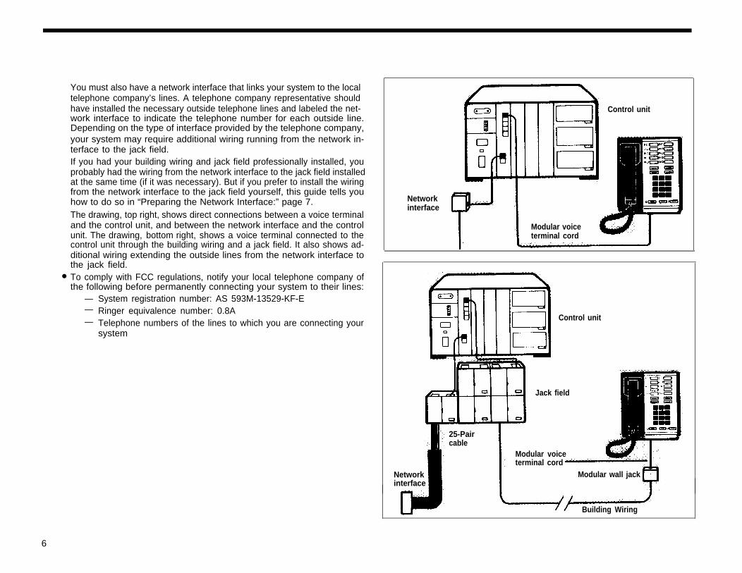
You must also have a network interface that links your system to the localtelephone company’s lines. A telephone company representative shouldhave installed the necessary outside telephone lines and labeled the net-work interface to indicate the telephone number for each outside line.Depending on the type of interface provided by the telephone company,your system may require additional wiring running from the network in-
Control unit
terface to the jack field.If you had your building wiring and jack field professionally installed, youprobably had the wiring from the network interface to the jack field installedat the same time (if it was necessary). But if you prefer to install the wiringfrom the network interface to the jack field yourself, this guide tells youhow to do so in “Preparing the Network Interface:” page 7.The drawing, top right, shows direct connections between a voice terminaland the control unit, and between the network interface and the controlunit. The drawing, bottom right, shows a voice terminal connected to thecontrol unit through the building wiring and a jack field. It also shows ad-ditional wiring extending the outside lines from the network interface to
Networkinterface
Modular voiceterminal cord
●
the jack field.To comply with FCC regulations, notify your local telephone company ofthe following before permanently connecting your system to their lines:
— System registration number: AS 593M-13529-KF-E— Ringer equivalence number: 0.8A— Telephone numbers of the lines to which you are connecting your
system
Control unit
Jack field
25-Paircable
Modular voiceterminal cord
Networkinterface
Modular wall jack
Building Wiring
6
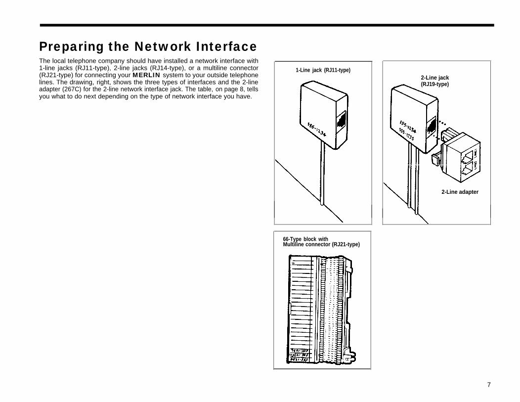
Preparing the Network InterfaceThe local telephone company should have installed a network interface with1-line jacks (RJ11-type), 2-line jacks (RJ14-type), or a multiline connector(RJ21-type) for connecting your MERLIN system to your outside telephonelines. The drawing, right, shows the three types of interfaces and the 2-lineadapter (267C) for the 2-line network interface jack. The table, on page 8, tellsyou what to do next depending on the type of network interface you have.
1-Line jack (RJ11-type)2-Line jack(RJ19-type)
2-Line adapter
66-Type block withMultiline connector (RJ21-type)
7
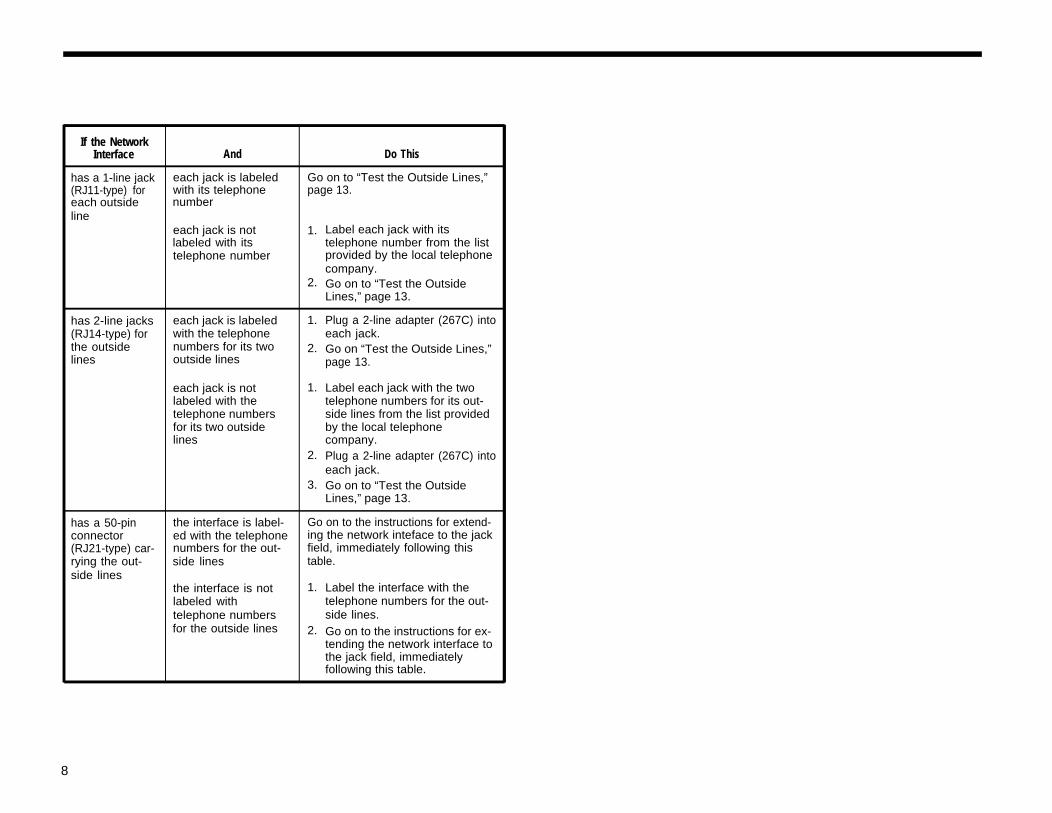
If the NetworkInterface And Do This
has a 1-line jack each jack is labeled Go on to “Test the Outside Lines,”(RJ11-type) for with its telephone page 13.each outside numberline
each jack is not 1. Label each jack with itslabeled with its telephone number from the listtelephone number provided by the local telephone
company.2. Go on to “Test the Outside
Lines,” page 13.
has 2-line jacks each jack is labeled 1. Plug a 2-line adapter (267C) into(RJ14-type) for with the telephone each jack.the outside numbers for its two 2. Go on “Test the Outside Lines,”lines outside lines page 13.
each jack is not 1. Label each jack with the twolabeled with the telephone numbers for its out-telephone numbers side lines from the list providedfor its two outside by the local telephonelines company.
2. Plug a 2-line adapter (267C) intoeach jack.
3. Go on to “Test the OutsideLines,” page 13.
has a 50-pin the interface is label- Go on to the instructions for extend-connector ed with the telephone ing the network inteface to the jack(RJ21-type) car- numbers for the out- field, immediately following thisrying the out- side lines table.side lines
the interface is not 1. Label the interface with thelabeled with telephone numbers for the out-telephone numbers side lines.for the outside lines 2. Go on to the instructions for ex-
tending the network interface tothe jack field, immediatelyfollowing this table.
8
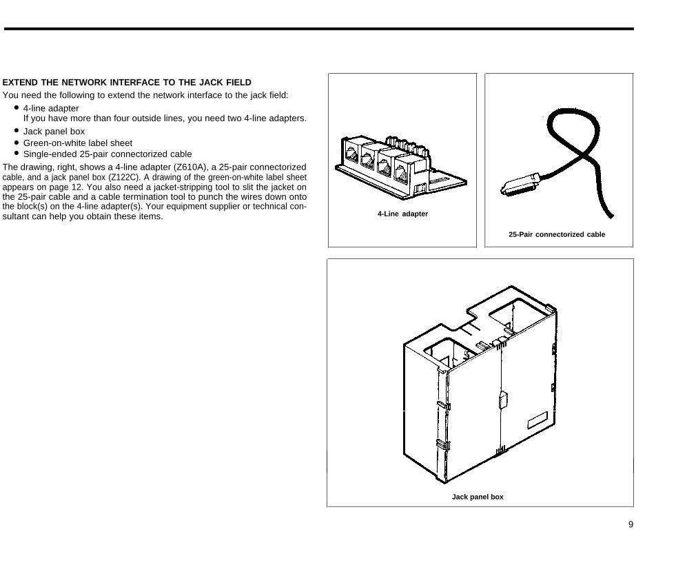
EXTEND THE NETWORK INTERFACE TO THE JACK FIELDYou need the following to extend the network interface to the jack field:
● 4-line adapterIf you have more than four outside lines, you need two 4-line adapters.
● Jack panel box● Green-on-white label sheet● Single-ended 25-pair connectorized cable
The drawing, right, shows a 4-line adapter (Z610A), a 25-pair connectorizedcable, and a jack panel box (Z122C). A drawing of the green-on-white label sheetappears on page 12. You also need a jacket-stripping tool to slit the jacket onthe 25-pair cable and a cable termination tool to punch the wires down ontothe block(s) on the 4-line adapter(s). Your equipment supplier or technical con-sultant can help you obtain these items. 4-Line adapter
25-Pair connectorized cable
Jack panel box
9
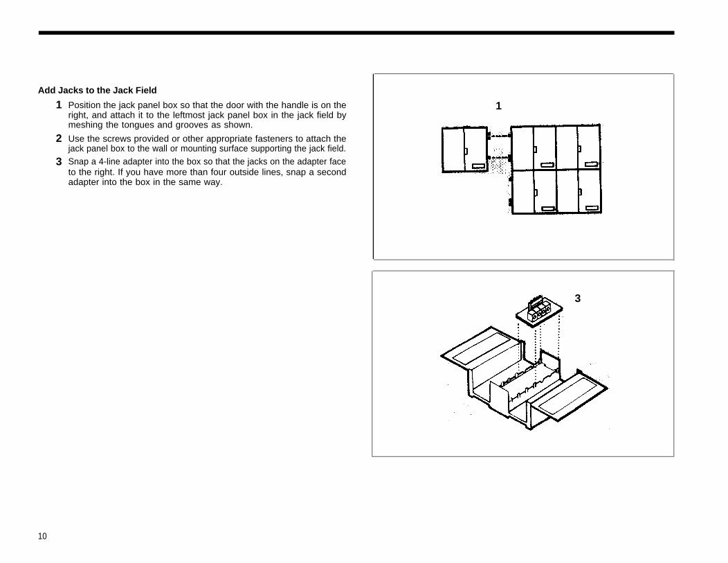
Add Jacks to the Jack Field
1
2
3
Position the jack panel box so that the door with the handle is on theright, and attach it to the leftmost jack panel box in the jack field bymeshing the tongues and grooves as shown.
Use the screws provided or other appropriate fasteners to attach thejack panel box to the wall or mounting surface supporting the jack field.Snap a 4-line adapter into the box so that the jacks on the adapter faceto the right. If you have more than four outside lines, snap a secondadapter into the box in the same way.
1
3
10
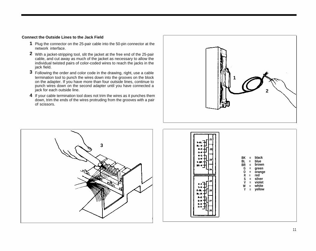
Connect the Outside Lines to the Jack Field
1
2
3
4
Plug the connector on the 25-pair cable into the 50-pin connector at thenetwork interface.
With a jacket-stripping tool, slit the jacket at the free end of the 25-paircable, and cut away as much of the jacket as necessary to allow theindividual twisted pairs of color-coded wires to reach the jacks in thejack field.
Following the order and color code in the drawing, right, use a cabletermination tool to punch the wires down into the grooves on the blockon the adapter. If you have more than four outside lines, continue topunch wires down on the second adapter until you have connected ajack for each outside line.
If your cable termination tool does not trim the wires as it punches themdown, trim the ends of the wires protruding from the grooves with a pair
1
2
of scissors.
3
BK =BL =BR =
G =O =R =S =V =
W =Y =
blackbluebrowngreenorangeredsilvervioletwhiteyellow
11
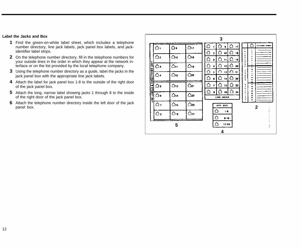
Label the Jacks and Box
1
2
3
4
5
6
Find the green-on-white label sheet, which includes a telephonenumber directory, line jack labels, jack panel box labels, and jack-identifier label strips.
On the telephone number directory, fill in the telephone numbers foryour outside lines in the order in which they appear at the network in-terface or on the list provided by the local telephone company.Using the telephone number directory as a guide, label the jacks in thejack panel box with the appropriate line jack labels.
Attach the label for jack panel box 1-8 to the outside of the right doorof the jack panel box.
Attach the long, narrow label showing jacks 1 through 8 to the insideof the right door of the jack panel box.
Attach the telephone number directory inside the left door of the jackpanel box.
3
54
2
12
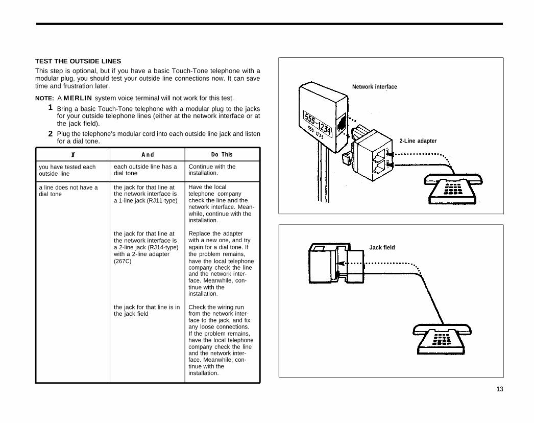
TEST THE OUTSIDE LINESThis step is optional, but if you have a basic Touch-Tone telephone with amodular plug, you should test your outside line connections now. It can savetime and frustration later. Network interface
NOTE: A MERLIN system voice terminal will not work for this test.1
2
Bring a basic Touch-Tone telephone with a modular plug to the jacksfor your outside telephone lines (either at the network interface or atthe jack field).
Plug the telephone’s modular cord into each outside line jack and listenfor a dial tone. 2-Line adapter
If A n d Do This
you have tested each each outside line has a Continue with theoutside line dial tone installation.
a line does not have a the jack for that line at Have the localdial tone the network interface is telephone company
a 1-line jack (RJ11-type) check the line and thenetwork interface. Mean-while, continue with theinstallation.
the jack for that line at Replace the adapterthe network interface is with a new one, and trya 2-line jack (RJ14-type) again for a dial tone. Ifwith a 2-line adapter the problem remains,(267C) have the local telephone
company check the lineand the network inter-face. Meanwhile, con-tinue with theinstallation.
the jack for that line is in Check the wiring runthe jack field from the network inter-
face to the jack, and fixany loose connections.If the problem remains,have the local telephonecompany check the lineand the network inter-face. Meanwhile, con-tinue with theinstallation.
Jack field
13
Installing the Control UnitYou need the following items to install the control unit:
●
●
●
●
Model 820 Control Unit Installation KitIt comes with your control unit and contains labels, two 7-foot line cords,a 2-line adapter, and a system directory. It also contains brackets, screws,and instructions for wall mounting the control unit.Control unitLine and Voice Terminal Modules and any cartridges, accessories, andadditional line cords that you orderedPower cord
5 feet, maximum
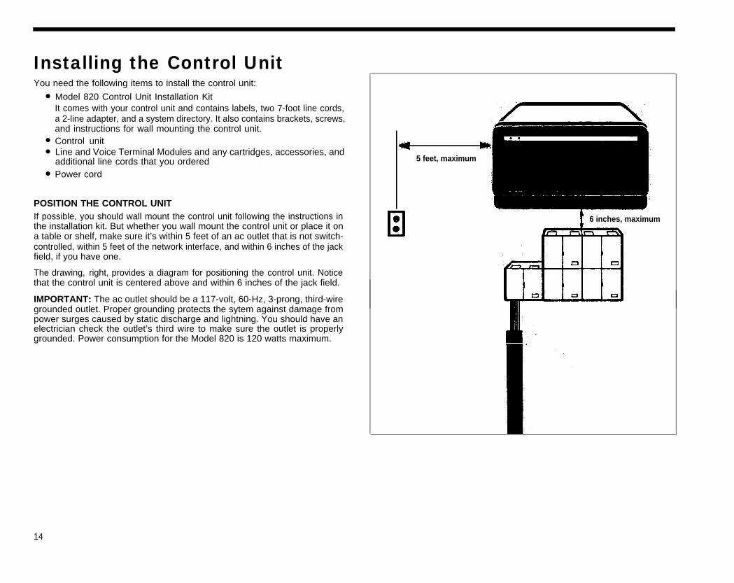
POSITION THE CONTROL UNITIf possible, you should wall mount the control unit following the instructions inthe installation kit. But whether you wall mount the control unit or place it ona table or shelf, make sure it’s within 5 feet of an ac outlet that is not switch-controlled, within 5 feet of the network interface, and within 6 inches of the jackfield, if you have one.
6 inches, maximum
The drawing, right, provides a diagram for positioning the control unit. Noticethat the control unit is centered above and within 6 inches of the jack field.
IMPORTANT: The ac outlet should be a 117-volt, 60-Hz, 3-prong, third-wiregrounded outlet. Proper grounding protects the sytem against damage frompower surges caused by static discharge and lightning. You should have anelectrician check the outlet’s third wire to make sure the outlet is properlygrounded. Power consumption for the Model 820 is 120 watts maximum.
14
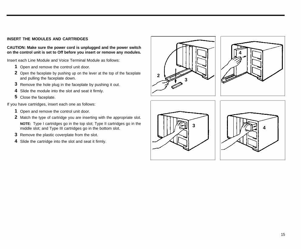
INSERT THE MODULES AND CARTRIDGES
CAUTION: Make sure the power cord is unplugged and the power switchon the control unit is set to Off before you insert or remove any modules.
Insert each Line Module and Voice Terminal Module as follows:
Open and remove the control unit door.
Open the faceplate by pushing up on the lever at the top of the faceplateand pulling the faceplate down.
Remove the hole plug in the faceplate by pushing it out.
Slide the module into the slot and seat it firmly.
Close the faceplate.
If you have cartridges, insert each one as follows:
4
23
12
345
12
34
Open and remove the control unit door.
Match the type of cartridge you are inserting with the appropriate slot.
NOTE: Type I cartridges go in the top slot; Type II cartridges go in themiddle slot; and Type III cartridges go in the bottom slot.
Remove the plastic coverplate from the slot.
Slide the cartridge into the slot and seat it firmly.
3 4
15
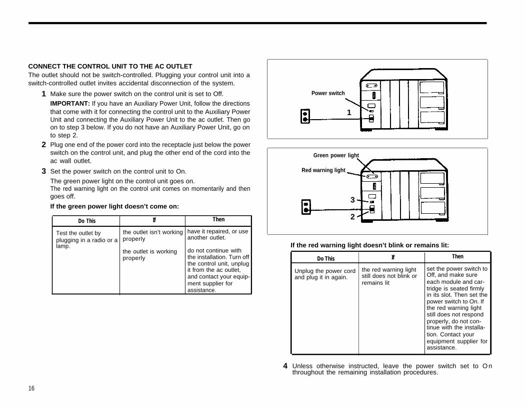
CONNECT THE CONTROL UNIT TO THE AC OUTLETThe outlet should not be switch-controlled. Plugging your control unit into aswitch-controlled outlet invites accidental disconnection of the system.
1
2
3
Make sure the power switch on the control unit is set to Off.
IMPORTANT: If you have an Auxiliary Power Unit, follow the directionsthat come with it for connecting the control unit to the Auxiliary PowerUnit and connecting the Auxiliary Power Unit to the ac outlet. Then goon to step 3 below. If you do not have an Auxiliary Power Unit, go onto step 2.Plug one end of the power cord into the receptacle just below the powerswitch on the control unit, and plug the other end of the cord into theac wall outlet.
Set the power switch on the control unit to On.
The green power light on the control unit goes on.The red warning light on the control unit comes on momentarily and then
Power switch
1
Green power light
goes off.
If the green power light doesn’t come on:
Do This If Then
Test the outlet by the outlet isn’t working have it repaired, or use
plugging in a radio or a properly another outlet.lamp.
the outlet is working do not continue withproperly the installation. Turn off
the control unit, unplugit from the ac outlet,and contact your equip-ment supplier forassistance.
Red warning light
3
2
4
If the red warning light doesn’t blink or remains lit:
Do This If
Unplug the power cord the red warning lightand plug it in again. still does not blink or
remains lit
Then
set the power switch toOff, and make sureeach module and car-tridge is seated firmlyin its slot. Then set thepower switch to On. Ifthe red warning lightstill does not respondproperly, do not con-tinue with the installa-tion. Contact yourequipment supplier forassistance.
Unless otherwise instructed, leave the power switch set to O nthroughout the remaining installation procedures.
16
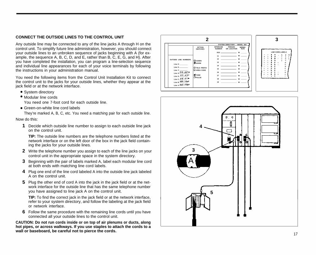
CONNECT THE OUTSIDE LINES TO THE CONTROL UNIT
Any outside line may be connected to any of the line jacks A through H on thecontrol unit. To simplify future line administration, however, you should connectyour outside lines to an unbroken sequence of jacks beginning with A (for ex-ample, the sequence A, B, C, D, and E, rather than B, C, E, G, and H). Afteryou have completed the installation, you can program a line-selection sequenceand individual line appearances for each of your voice terminals by followingthe instructions in your administration manual.
You need the following items from the Control Unit Installation Kit to connectthe control unit to the jacks for your outside lines, whether they appear at thejack field or at the network interface.
System directoryModular line cordsYou need one 7-foot cord for each outside line.Green-on-white line cord labelsThey’re marked A, B, C, etc. You need a matching pair for each outside line.
Now do this:
W LINE CORD LABELS
11 W
ADMIN
Line H
Line G
Line F
Line E
Line D
Line C
Line B
Line A
NORM
●
●
●
1
2
3
4
5
6
Decide which outside line number to assign to each outside line jackon the control unit.
TIP: The outside line numbers are the telephone numbers listed at thenetwork interface or on the left door of the box in the jack field contain-ing the jacks for your outside lines.
Write the telephone number you assign to each of the line jacks on yourcontrol unit in the appropriate space in the system directory.Beginning with the pair of labels marked A, label each modular line cordat both ends with matching line cord labels.
Plug one end of the line cord labeled A into the outside line jack labeledA on the control unit.
Plug the other end of cord A into the jack in the jack field or at the net-work interface for the outside line that has the same telephone numberyou have assigned to line jack A on the control unit.
TIP: To find the correct jack in the jack field or at the network interface,refer to your system directory, and follow the labeling at the jack fieldor network interface.
Follow the same procedure with the remaining line cords until you have
4
3
A
5
connected all your outside lines to the control unit.
CAUTION: Do not run cords inside or on top of air plenums or ducts, alonghot pipes, or across walkways. If you use staples to attach the cords to awall or baseboard, be careful not to pierce the cords.
2SYSTEM DIRECTORY – MODEL 820
OPTION INTERCOM PERSON WIRINGSWITCHES NUMBER OR LOCATION RUN
0/10
OUTSIDE LINE NUMBERS
TELE PREFIX
AREA CODE
TONE
PULSE
12 W
13 W
14 W
15 W
16 W
17 W
18 W
19 W
3
17
Voice Terminal WiringThe intercom number for each voice terminal in your MERLIN system is thesame as the number of the voice terminal jack in the control unit to which thatvoice terminal is connected. On a Model 820 control unit, the voice terminaljacks are labeled 10-29. If you want a particular intercom number at a specificlocation within your business (for example, intercom 10 at the attendant’s loca-tion), make a note of the assignment now, before you begin connecting the voiceterminal locations to the system.
As noted in “Getting Started,” you can connect your voice terminal locationsto the control unit in either of two ways: (1) directly, with modular voice terminalcords and, if necessary, modular voice terminal extension cords; or (2) indirectly,through the building wiring to a jack field at the control unit location.
Whichever procedure you use, you need the following items from the installa-tion kit to complete the connections:
●
●
●
System directoryYou’ve already recorded the telephone numbers for your outside lines on it.Modular jumper cordsYou should have one 2½-foot cord for each voice terminal in your system.If you have a professionally installed jack field, these cords may be hang-ing from the jacks in the jack field. If they are, remove them now.Blue-on-white jumper cord labelsThe labels are numbered 10 through 29. You should have a matched pairof labels for each cord.
The next two sections give directions for a jack field connection and a directconnection. Go to the section that applies to your system and do what it says.
18
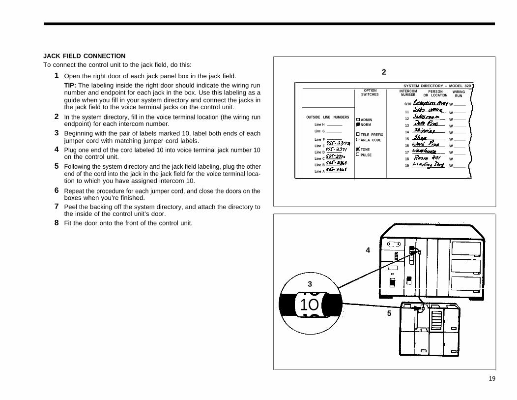
JACK FIELD CONNECTlONTo connect the control unit to the jack field, do this:
1
2
3
4
5
6
7
8
Open the right door of each jack panel box in the jack field.TIP: The labeling inside the right door should indicate the wiring runnumber and endpoint for each jack in the box. Use this labeling as aguide when you fill in your system directory and connect the jacks inthe jack field to the voice terminal jacks on the control unit.
In the system directory, fill in the voice terminal location (the wiring runendpoint) for each intercom number.
Beginning with the pair of labels marked 10, label both ends of eachjumper cord with matching jumper cord labels.Plug one end of the cord labeled 10 into voice terminal jack number 10on the control unit.
Following the system directory and the jack field labeling, plug the otherend of the cord into the jack in the jack field for the voice terminal loca-tion to which you have assigned intercom 10.
Repeat the procedure for each jumper cord, and close the doors on theboxes when you’re finished.Peel the backing off the system directory, and attach the directory tothe inside of the control unit’s door.Fit the door onto the front of the control unit.
2
SYSTEM DIRECTORY – MODEL 820INTERCOM PERSON WIRINGNUMBER OR LOCATION RUN
0/10 W
OUTSIDE LINE NUMBERS
Line H
Line G
OPTIONSWITCHES
ADMINNORM
TELE PREFIXAREA CODE
TONEPULSE
Line F
Line E
Line D
Line C
Line B
Line A
11
12
13
14
15
16
17
18
19
W
W
W
W
W
W
W
W
W
4
3
1O5
19

DIRECT CONNECTIONTo connect your voice terminal locations directly to the control unit, do this:
1
1 SYSTEM DIRECTORY – MODEL 820OPTION INTERCOM PERSON WIRING
NUMBER OR LOCATION RUN
2 0/10
11
12
13
14
15
16
17
18
19
W
W
W
W
W
W
W
W
W
W
3
4
5
6
In the system directory, fill in the voice terminal location you haveselected for each intercom number.Beginning with the pair of labels marked 10, label each cord at both endswith matching labels.
TIP: If the distance between a voice terminal location and the controlunit requires the use of extension cords, label each end of the wiringrun. Attach one label near the plug to the voice terminal and thematching label near the plug to the control unit.
Run the cords from the voice terminal locations to the control unit.CAUTION: Do not run cords inside or on top of air plenums or ducts,along hot pipes, or across walkways. If you use staples to attachcords to walls or baseboards, be careful not to pierce the cords.
Plug each cord into the voice terminal jack on the control unit with thesame number as the cord label.
Peel the backing off the system directory, and attach the directory tothe inside of the control unit’s door.Fit the door onto the front of the control unit.
SWITCHES
OUTSIDE LINE NUMBERS ADMIN
Line H NORM
Line G TELE PREFIXLine F AREA CODELineELine D TONE
PULSELine CLine B
Line A
4 33
Modular voice terminalextension cords
400 feet maximum
20
Connecting the Voice TerminalsThere are several types of voice terminals available. Some are more practicalfor employees with limited need for custom features and access to multiple out-side lines. Others are designed for employees who need access to manycustom features or outside lines. A 34-button deluxe voice terminal, with lightsby every flat button, is most appropriate for an attendant or receptionist.
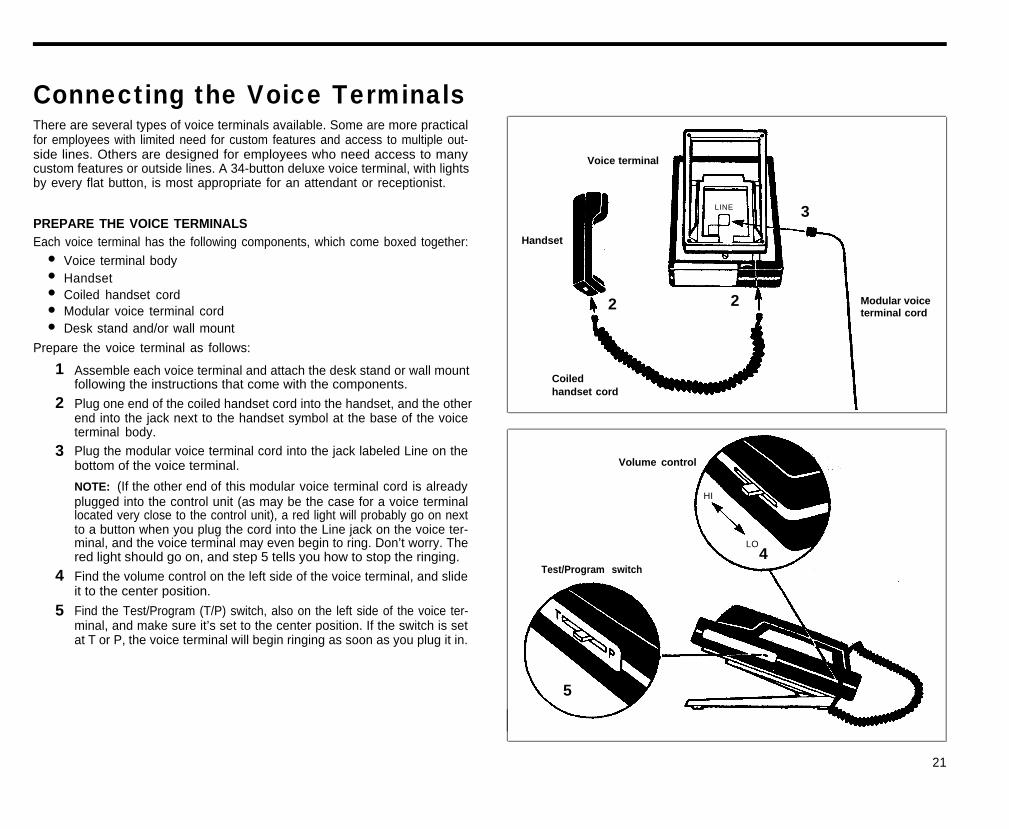
PREPARE THE VOICE TERMINALSEach voice terminal has the following components, which come boxed together:
Voice terminal bodyHandsetCoiled handset cordModular voice terminal cordDesk stand and/or wall mount
Prepare the voice terminal as follows:
Voice terminal
LINE 3
Handset
●
●
●
●
●
2 2 Modular voiceterminal cord
1
2
3
4
5
Assemble each voice terminal and attach the desk stand or wall mountfollowing the instructions that come with the components.
Plug one end of the coiled handset cord into the handset, and the otherend into the jack next to the handset symbol at the base of the voiceterminal body.Plug the modular voice terminal cord into the jack labeled Line on thebottom of the voice terminal.
NOTE: (If the other end of this modular voice terminal cord is alreadyplugged into the control unit (as may be the case for a voice terminallocated very close to the control unit), a red light will probably go on nextto a button when you plug the cord into the Line jack on the voice ter-minal, and the voice terminal may even begin to ring. Don’t worry. Thered light should go on, and step 5 tells you how to stop the ringing.
Find the volume control on the left side of the voice terminal, and slideit to the center position.
Find the Test/Program (T/P) switch, also on the left side of the voice ter-minal, and make sure it’s set to the center position. If the switch is setat T or P, the voice terminal will begin ringing as soon as you plug it in.
Coiledhandset cord
Volume control
Test/Program switch
HI
LO4
5
21
12
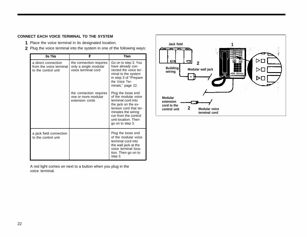
CONNECT EACH VOICE TERMINAL TO THE SYSTEM
Place the voice terminal in its designated location.Plug the voice terminal into the system in one of the following ways:
Do This If Then
a direct connection the connection requires Go on to step 3. Youfrom the voice terminal only a single modular have already con-to the control unit voice terminal cord nected the voice ter-
minal to the systemin step 3 of “Preparethe Voice Ter-minals,” page 22.
the connection requires Plug the loose endone or more modular of the modular voiceextension cords terminal cord into
the jack on the ex-tension cord that ter-minates the wiringrun from the controlunit location. Thengo on to step 3.
a jack field connection Plug the loose endto the control unit of the modular voice
terminal cord intothe wall jack at thevoice terminal loca-tion. Then go on tostep 3.
Jack field
2
1
Buildingwiring
Modular wall jack
Modularextensioncord to thecontrol unit 2 Modular voice
terminal cord
A red light comes on next to a button when you plug in thevoice terminal.
22
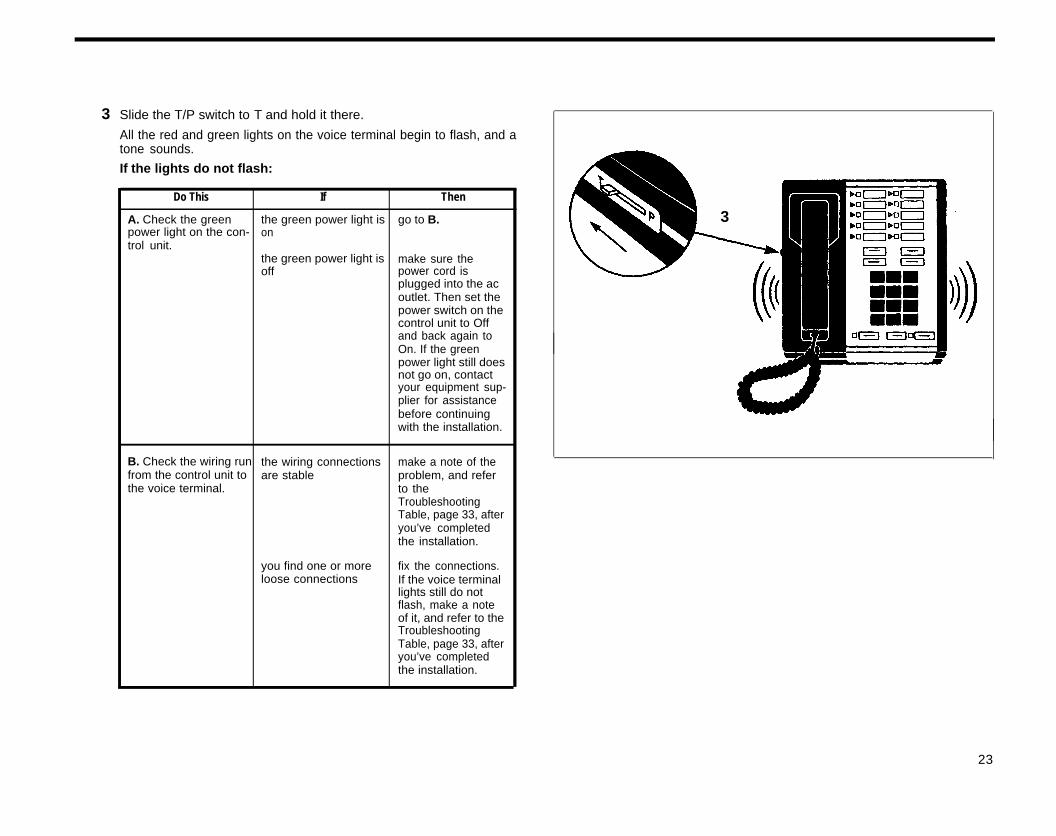
3 Slide the T/P switch to T and hold it there.
All the red and green lights on the voice terminal begin to flash, and atone sounds.
If the lights do not flash:
Do This If Then
A. Check the green the green power light is go to B.power light on the con- ontrol unit.
the green power light is make sure theoff power cord is
plugged into the acoutlet. Then set thepower switch on thecontrol unit to Offand back again toOn. If the greenpower light still doesnot go on, contactyour equipment sup-plier for assistancebefore continuingwith the installation.
B. Check the wiring run the wiring connections make a note of thefrom the control unit to are stable problem, and referthe voice terminal. to the
TroubleshootingTable, page 33, afteryou’ve completedthe installation.
you find one or more fix the connections.loose connections If the voice terminal
lights still do notflash, make a noteof it, and refer to theTroubleshootingTable, page 33, afteryou’ve completedthe installation.
3
23
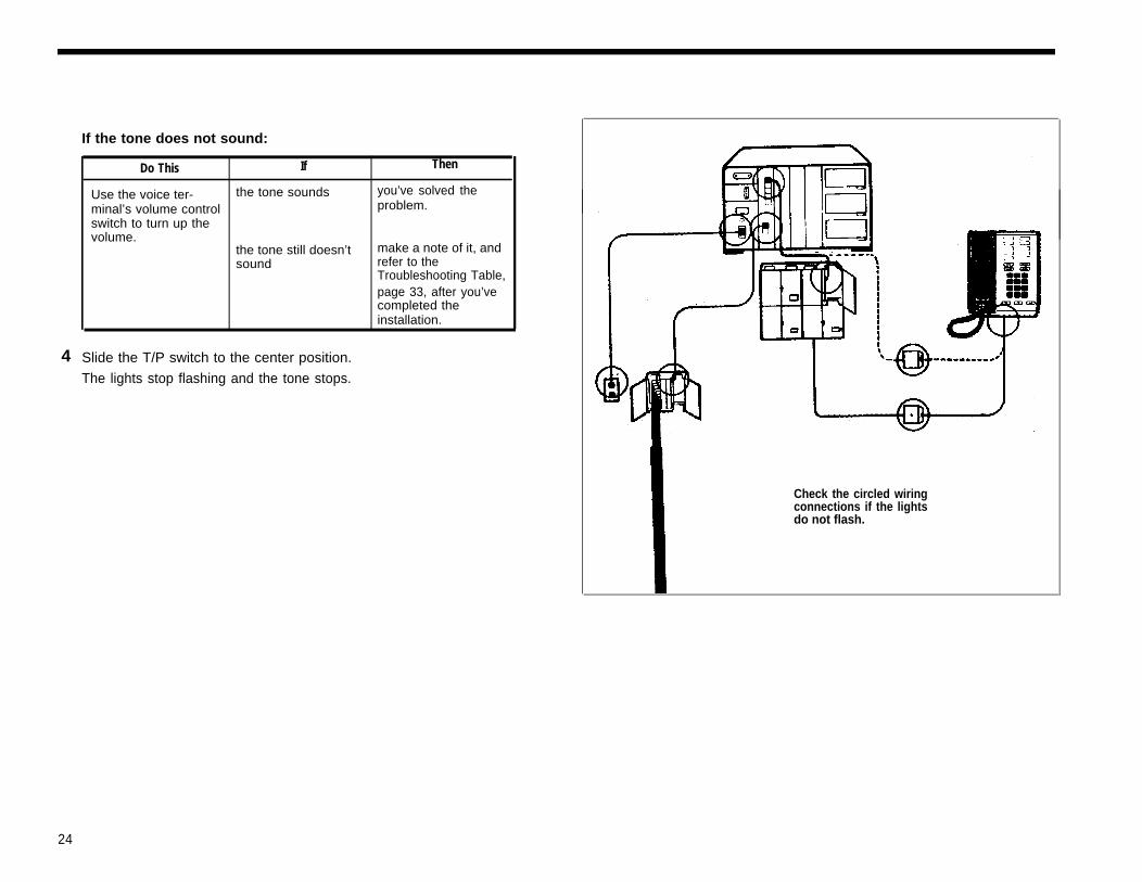
If the tone does not sound:
Do This If Then
Use the voice ter- the tone sounds you’ve solved the
minal’s volume control problem.switch to turn up thevolume.
the tone still doesn’t make a note of it, andsound refer to the
Troubleshooting Table,page 33, after you’vecompleted theinstallation.
4 Slide the T/P switch to the center position.
The lights stop flashing and the tone stops.
Check the circled wiringconnections if the lightsdo not flash.
24
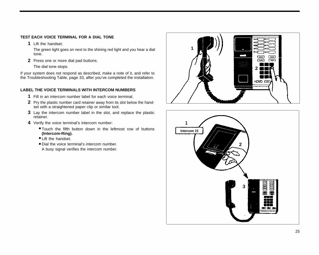
TEST EACH VOICE TERMINAL FOR A DIAL TONE
1
2
Lift the handset.The green light goes on next to the shining red light and you hear a dialtone.
Press one or more dial pad buttons.
1
The dial tone stops.
If your system does not respond as described, make a note of it, and refer tothe Troubleshooting Table, page 33, after you’ve completed the installation.
LABEL THE VOICE TERMINALS WITH INTERCOM NUMBERS
2
12
3
4
Fill in an intercom number label for each voice terminal.
Pry the plastic number card retainer away from its slot below the hand-set with a straightened paper clip or similar tool.
Lay the intercom number label in the slot, and replace the plasticretainer.
Verify the voice terminal’s intercom number:
Touch the fifth button down in the leftmost row of buttons(Intercom-Ring).Lift the handset.Dial the voice terminal’s intercom number.A busy signal verifies the intercom number.
1●
●
●
Intercom 15
2
3
25
Installing AccessoriesOnce you have installed your MERLIN system, you may want to add ac-cessories to enhance its capabilities.
CARTRIDGESCartridges provide the software and interfaces that make it possible for you touse many of the MERLIN system features and accessories. With Type I car-tridges, called Feature Packages, you can have access to features such as Con-ference Calling, Call Pickup, Call Transfer, and Outward Call Restriction.Without any cartridges you still have standard features, which include AutomaticLine Selection, Hold, and Intercom. Type II cartridges provide Music-on-Holdand Loudspeaker Paging capabilities. Type III cartridges provide Extra Alertand Power Failure Transfer capabilities. See page 15 for information on inser-ting cartridges in the control unit.
ACCESSORY EQUIPMENTGeneral Purpose Adapters allow you to connect Touch-Tone (not rotary) equip-ment such as modems, autodialers, and telephone extensions (including cor-dless telephones) to your voice terminals.
Supplemental Alert Adapters enable you to connect alerting devices such ashorns, bells, and strobe lights to your system.
If you need to add one or more voice terminals or outside lines to your system,add a 2-Line Module, a 5-Voice Terminal Module, or a 2-Line/5-Voice TerminalModule to your control unit.
POWER ACCESSORIESYou may find it necessary to add auxiliary power components to your system.For example, you may need a Voice Terminal Power Supply for a 34-buttondeluxe voice terminal with an accessory connected to it or for a voice terminallocated more than 1000 feet from the control unit. Or you may need an Aux-iliary Power Unit for your control unit if many of your voice terminals have anaccessory but do not have a Voice Terminal Power Supply.
If the lights on some of your voice terminals become dim or go out altogetherwhen many employees use their voice terminals at the same time, you probablyneed one or more auxiliary power components. If you know you need additionalpower, do not use all your accessories until you can supply enough power toyour system.
It may be more economical to provide Voice Terminal Power Supplies for yourvoice terminals than to get an Auxiliary Power Unit for your control unit. Yourequipment supplier can help you make the most cost-effective addition to yoursystem.
To add power and other accessories to your system, follow the instructions thatcome with the components.
26
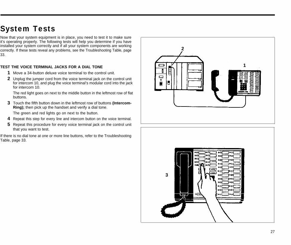
System TestsNow that your system equipment is in place, you need to test it to make sureit’s operating properly. The following tests will help you determine if you haveinstalled your system correctly and if all your system components are workingcorrectly. If these tests reveal any problems, see the Troubleshooting Table, page33.
2
TEST THE VOICE TERMINAL JACKS FOR A DIAL TONE 1
12
3
45
Move a 34-button deluxe voice terminal to the control unit.
Unplug the jumper cord from the voice terminal jack on the control unitfor intercom 10, and plug the voice terminal’s modular cord into the jackfor intercom 10.
The red light goes on next to the middle button in the leftmost row of flatbuttons.
Touch the fifth button down in the leftmost row of buttons (Intercom-Ring); then pick up the handset and verify a dial tone.
The green and red lights go on next to the button.
Repeat this step for every line and intercom button on the voice terminal.
Repeat this procedure for every voice terminal jack on the control unitthat you want to test.
If there is no dial tone at one or more line buttons, refer to the TroubleshootingTable, page 33.
3
27
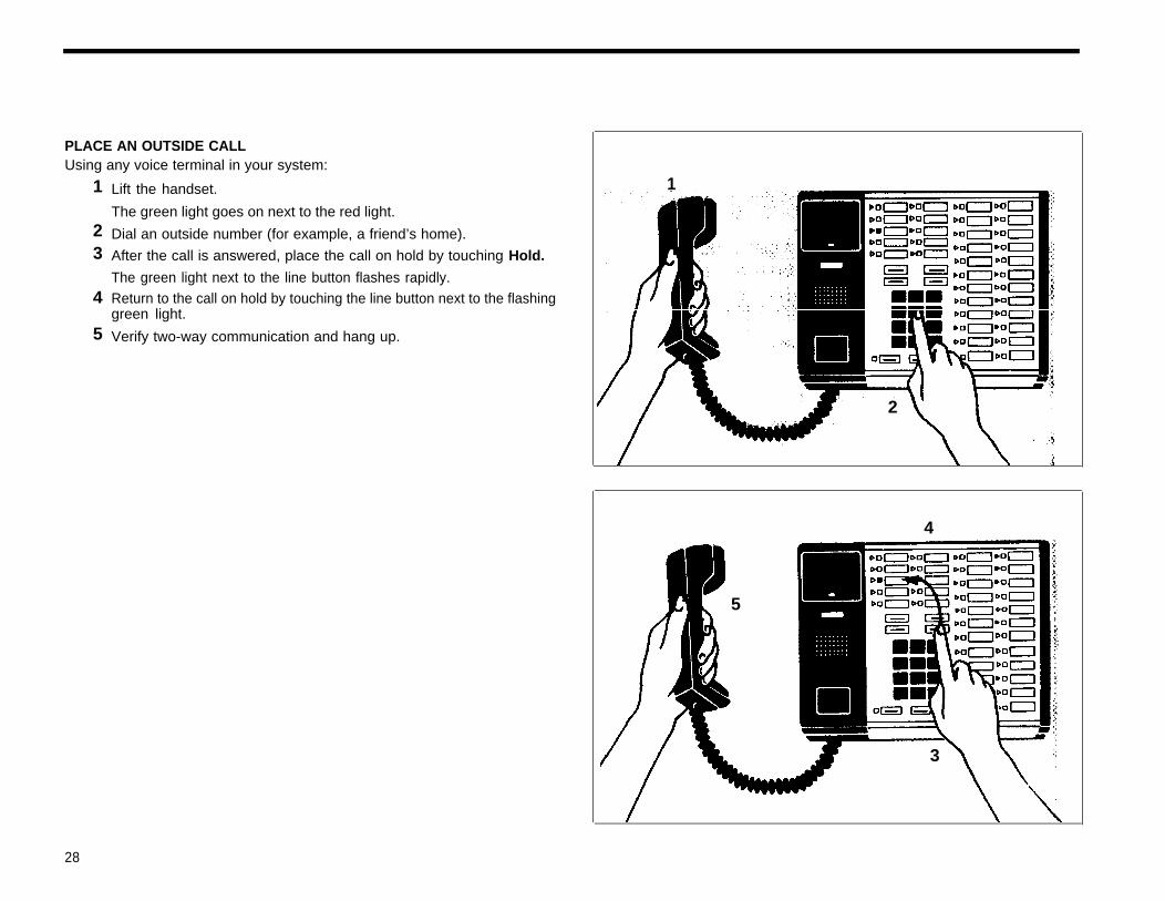
PLACE AN OUTSIDE CALLUsing any voice terminal in your system:
1
23
4
5
Lift the handset.
The green light goes on next to the red light.
1
Dial an outside number (for example, a friend’s home).
After the call is answered, place the call on hold by touching Hold.
The green light next to the line button flashes rapidly.Return to the call on hold by touching the line button next to the flashinggreen light.
Verify two-way communication and hang up.
2
4
5
3
28
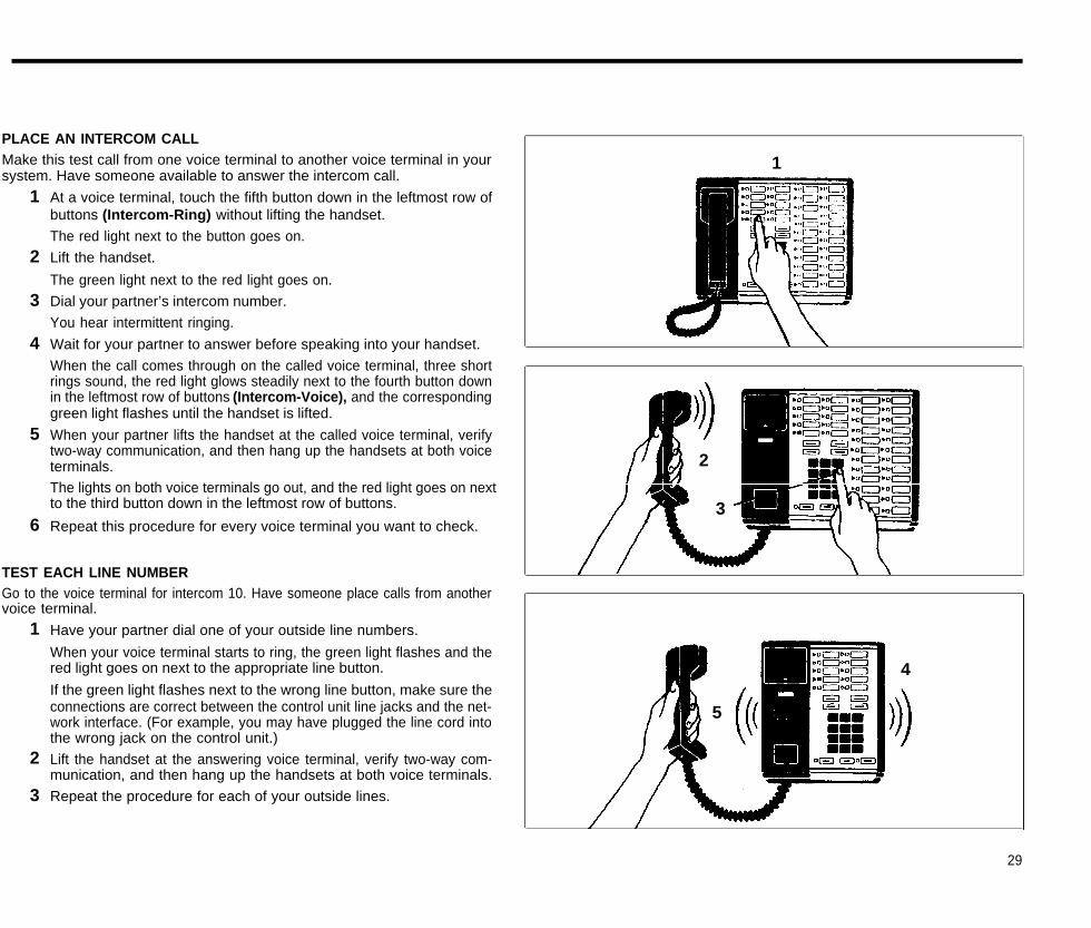
PLACE AN INTERCOM CALLMake this test call from one voice terminal to another voice terminal in yoursystem. Have someone available to answer the intercom call.
1
1
2
3
4
5
6
At a voice terminal, touch the fifth button down in the leftmost row ofbuttons (Intercom-Ring) without lifting the handset.
The red light next to the button goes on.
Lift the handset.
The green light next to the red light goes on.
Dial your partner’s intercom number.
You hear intermittent ringing.
Wait for your partner to answer before speaking into your handset.
When the call comes through on the called voice terminal, three shortrings sound, the red light glows steadily next to the fourth button downin the leftmost row of buttons (Intercom-Voice), and the correspondinggreen light flashes until the handset is lifted.
When your partner lifts the handset at the called voice terminal, verifytwo-way communication, and then hang up the handsets at both voiceterminals.The lights on both voice terminals go out, and the red light goes on nextto the third button down in the leftmost row of buttons.
Repeat this procedure for every voice terminal you want to check.
2
3
TEST EACH LINE NUMBERGo to the voice terminal for intercom 10. Have someone place calls from anothervoice terminal.
1
2
3
Have your partner dial one of your outside line numbers.
When your voice terminal starts to ring, the green light flashes and thered light goes on next to the appropriate line button.
If the green light flashes next to the wrong line button, make sure theconnections are correct between the control unit line jacks and the net-work interface. (For example, you may have plugged the line cord intothe wrong jack on the control unit.)
Lift the handset at the answering voice terminal, verify two-way com-munication, and then hang up the handsets at both voice terminals.
Repeat the procedure for each of your outside lines.
4
5
29
What’s Next?
●
●
●
●
Now that your MERLIN system is installed, you need to program it to meet yourbusiness needs. See your administration manual to learn how to:
Assign voice terminals to attendantsAdminister your MERLIN systemAssign individual lines and call restrictions to individual voice terminalsProgram individual voice terminals
Once you’ve customized the system to meet your business needs, review theuser’s guide to learn how to use the MERLIN system custom features.
This installation guide contains information about system changes andtroubleshooting. Keep it for later reference.
30
System ChangesYour MERLIN communications system is designed so that you can makechanges quickly and easily. You can increase your system’s capacity by ad-ding outside lines or voice terminals. Modular plugs on much of the system wir-ing and the labels on key components make it easy for you to reorganize thesystem in the event of office rearrangements.
The following are the most common system changes.
ADDING AN OUTSIDE LINEIf your MERLIN system becomes so busy that people in your office frequent-ly must wait to make calls, you may want to add one or more outside lines toyour system. Your system may have up to eight outside lines.
1
2
3
4
Have your local telephone company add the outside line(s) and networkinterface jack(s) to those you already have in place.
If you have fewer than four Voice Terminal Modules and/or Line Modulesin your control unit and all the line jacks in these modules are full, youcan add a 2-Line Module or a 2-Line/5-Voice Terminal Module.To install a module, refer to “Insert the Modules and Cartridges,” page15.Label a new line button on each voice terminal that will have accessto the new line(s). If you have a Feature Package, refer to the administra-tion manual that came with it for instructions on assigning a line to avoice terminal.
Record the changes in your system directory.
ADDING A VOICE TERMINALYou can easily add more voice terminals to your MERLIN system as yourbusiness and communication demands increase. Your system can accom-modate up to 20 voice terminals.
To add a voice terminal to your system:
1
2
3
4
See that the necessary wiring, jacks, and jumper cords are installedbetween the control unit and the new voice terminal location (refer to“Voice Terminal Wiring,” page 18, and “Getting Started,” page 3).
If all the voice terminal jacks in the Voice Terminal Modules in your con-trol unit are full, and you have fewer than four Voice Terminal Modules,you can add a 2-Line/5-Voice Terminal Module or a 5-Voice Terminal Ex-pansion Module for Model 820.
If your system has a jack field, label each new jack in the jack field withits wiring run end point (for example, “Workshop” or “Reception Area”).
If you do not have a jack field, go on to the next step.
To add a module, refer to “Insert the Modules and Cartridges,” page15. To add voice terminals, refer to “Voice Terminal Wiring”, page 18,and “Connecting the Voice Terminals,” page 21.Record the addition in your system directory.
31
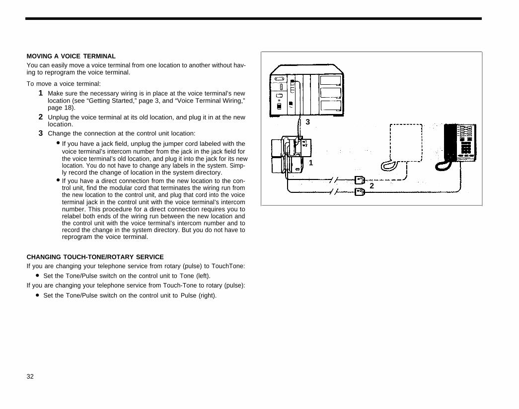
MOVING A VOICE TERMINALYou can easily move a voice terminal from one location to another without hav-ing to reprogram the voice terminal.
To move a voice terminal:
1
2
3
Make sure the necessary wiring is in place at the voice terminal’s newlocation (see “Getting Started,” page 3, and “Voice Terminal Wiring,”page 18).
Unplug the voice terminal at its old location, and plug it in at the newlocation.Change the connection at the control unit location:
3
●
1
●
If you have a jack field, unplug the jumper cord labeled with thevoice terminal’s intercom number from the jack in the jack field forthe voice terminal’s old location, and plug it into the jack for its newlocation. You do not have to change any labels in the system. Simp-ly record the change of location in the system directory.If you have a direct connection from the new location to the con-trol unit, find the modular cord that terminates the wiring run fromthe new location to the control unit, and plug that cord into the voiceterminal jack in the control unit with the voice terminal’s intercomnumber. This procedure for a direct connection requires you torelabel both ends of the wiring run between the new location andthe control unit with the voice terminal’s intercom number and torecord the change in the system directory. But you do not have toreprogram the voice terminal.
2
●
●
CHANGING TOUCH-TONE/ROTARY SERVICEIf you are changing your telephone service from rotary (pulse) to TouchTone:
Set the Tone/Pulse switch on the control unit to Tone (left).
If you are changing your telephone service from Touch-Tone to rotary (pulse):
Set the Tone/Pulse switch on the control unit to Pulse (right).
32
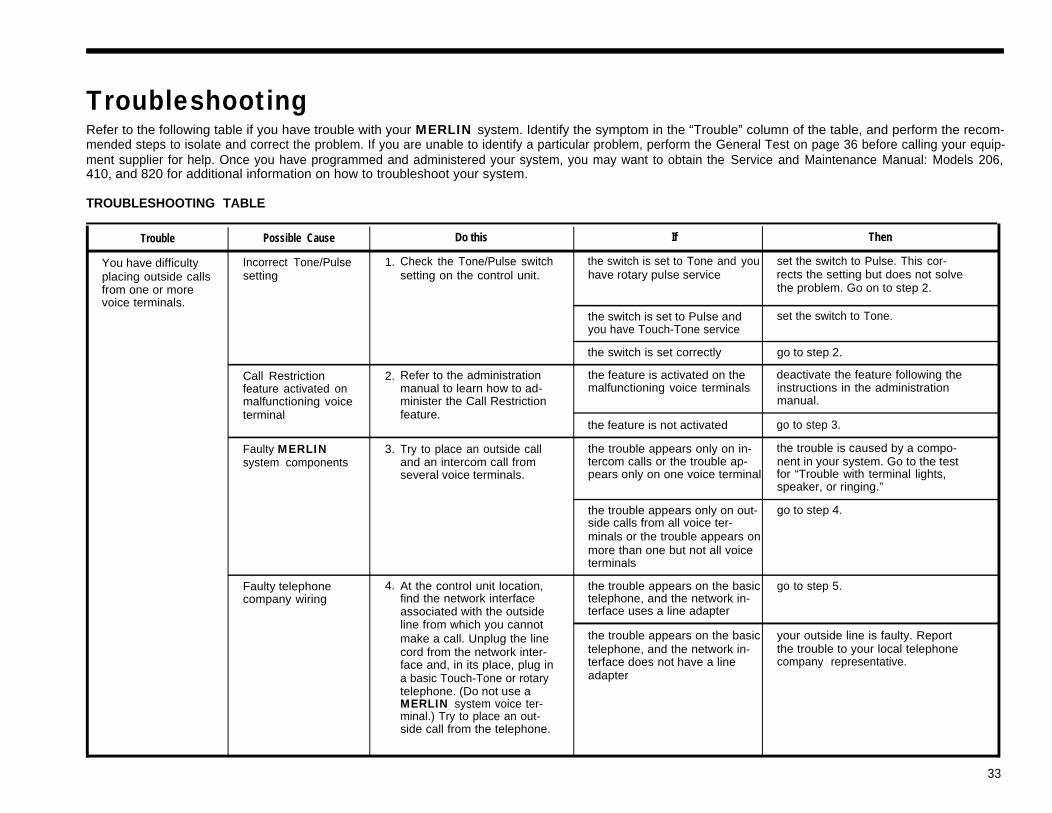
TroubleshootingRefer to the following table if you have trouble with your MERLIN system. Identify the symptom in the “Trouble” column of the table, and perform the recom-mended steps to isolate and correct the problem. If you are unable to identify a particular problem, perform the General Test on page 36 before calling your equip-ment supplier for help. Once you have programmed and administered your system, you may want to obtain the Service and Maintenance Manual: Models 206,410, and 820 for additional information on how to troubleshoot your system.
TROUBLESHOOTING TABLE
Trouble Possible Cause Do this If Then
You have difficulty Incorrect Tone/Pulse 1. Check the Tone/Pulse switch the switch is set to Tone and you set the switch to Pulse. This cor-placing outside calls setting setting on the control unit. have rotary pulse service rects the setting but does not solvefrom one or more the problem. Go on to step 2.voice terminals.
the switch is set to Pulse and set the switch to Tone.you have Touch-Tone service
the switch is set correctly go to step 2.
Call Restriction 2. Refer to the administration the feature is activated on the deactivate the feature following thefeature activated on manual to learn how to ad- malfunctioning voice terminals instructions in the administrationmalfunctioning voice minister the Call Restriction manual.terminal feature.
the feature is not activated go to step 3.
Faulty MERLIN 3. Try to place an outside call the trouble appears only on in- the trouble is caused by a compo-system components and an intercom call from tercom calls or the trouble ap- nent in your system. Go to the test
several voice terminals. pears only on one voice terminal for “Trouble with terminal lights,speaker, or ringing.”
the trouble appears only on out- go to step 4.side calls from all voice ter-minals or the trouble appears onmore than one but not all voiceterminals
Faulty telephone 4. At the control unit location, the trouble appears on the basic go to step 5.company wiring find the network interface telephone, and the network in-
associated with the outside terface uses a line adapterline from which you cannotmake a call. Unplug the line the trouble appears on the basic your outside line is faulty. Reportcord from the network inter- telephone, and the network in- the trouble to your local telephoneface and, in its place, plug in terface does not have a line company representative.a basic Touch-Tone or rotary adaptertelephone. (Do not use aMERLIN system voice ter-minal.) Try to place an out-side call from the telephone.
33
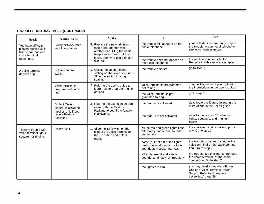
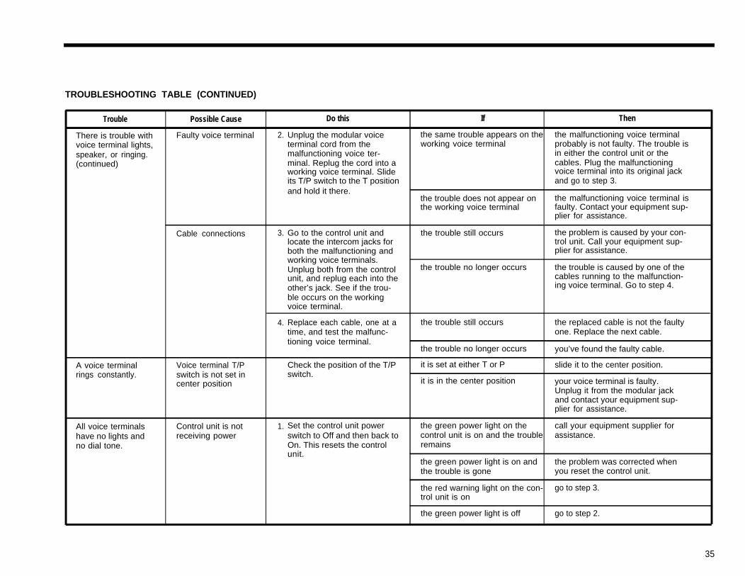
TROUBLESHOOTING TABLE (CONTINUED)
Trouble
You have difficultyplacing outside callsfrom more than onevoice terminal.(continued)
A voice terminaldoesn’t ring.
There is trouble withvoice terminal lights,speaker, or ringing.
Possible Cause
Faulty network inter-face line adapter
Volume controlswitch
Voice terminal isprogrammed not toring
Do Not Disturbfeature is activated(applies only if youhave a FeaturePackage)
Control unit
Do this If Then
Replace the network inter- the trouble still appears on the your outside lines are faulty. Report
face’s line adapter with basic telephone the trouble to your local telephone
another one. Plug the basic company representative.
telephone into each of thejacks, and try to place an out-side call. the trouble does not appear on the old line adapter is faulty.
the basic telephone Replace it with a new line adapter.
Check the volume control the trouble persists go to step 2.
setting on the voice terminal.Slide the switch to a highsetting.
Refer to the user’s guide to voice terminal is programmed change the ringing option following
learn how to program ringing not to ring the instructions in the user’s guide.
options.the voice terminal is pro- go to step 3.grammed to ring
5.
1.
2.
3.
1.
Refer to the user’s guide that the feature is activated deactivate the feature following the
came with the Feature instructions in the user’s guide.
Package to see if the featureis activated.
the feature is not activated refer to the test for “Trouble withlights, speakers, and ringing,”below.
Slide the T/P switch on the all the red and green lights flash the voice terminal is working prop-
side of the voice terminal to alternately and a tone sounds erly. Go to step 3.
the T position and hold it continuallythere.
some (but not all) of the lights the trouble is caused by either theflash continually and/or a tone voice terminal or the cable connec-sounds at irregular intervals tion. Go to step 2.
all lights are off and a tone the trouble is either the control unit,sounds continually or irregularly the voice terminal, or the cable
connection. Go to step 2.
the lights are dim you may need an Auxiliary PowerUnit or a Voice Terminal PowerSupply. Refer to “Power Ac-cessories,” page 26.
34
TROUBLESHOOTING TABLE (CONTINUED)
Trouble Possible Cause Do this If Then
There is trouble with Faulty voice terminal 2. Unplug the modular voice the same trouble appears on the the malfunctioning voice terminalvoice terminal lights, terminal cord from the working voice terminal probably is not faulty. The trouble isspeaker, or ringing. malfunctioning voice ter- in either the control unit or the(continued) minal. Replug the cord into a cables. Plug the malfunctioning
working voice terminal. Slide voice terminal into its original jackits T/P switch to the T position and go to step 3.and hold it there.
the trouble does not appear on the malfunctioning voice terminal isthe working voice terminal faulty. Contact your equipment sup-
plier for assistance.
Cable connections 3. Go to the control unit and the trouble still occurs the problem is caused by your con-locate the intercom jacks for trol unit. Call your equipment sup-both the malfunctioning and plier for assistance.working voice terminals.Unplug both from the control the trouble no longer occurs the trouble is caused by one of theunit, and replug each into the cables running to the malfunction-other’s jack. See if the trou- ing voice terminal. Go to step 4.
ble occurs on the workingvoice terminal.
4. Replace each cable, one at a the trouble still occurs the replaced cable is not the faultytime, and test the malfunc- one. Replace the next cable.tioning voice terminal.
the trouble no longer occurs you’ve found the faulty cable.
A voice terminal Voice terminal T/P Check the position of the T/P it is set at either T or P slide it to the center position.rings constantly. switch is not set in switch.
center position it is in the center position your voice terminal is faulty.Unplug it from the modular jackand contact your equipment sup-plier for assistance.
All voice terminals Control unit is not 1. Set the control unit power the green power light on the call your equipment supplier forhave no lights and receiving power switch to Off and then back to control unit is on and the trouble assistance.no dial tone. On. This resets the control remains
unit.the green power light is on and the problem was corrected whenthe trouble is gone you reset the control unit.
the red warning light on the con- go to step 3.trol unit is on
the green power light is off go to step 2.
35
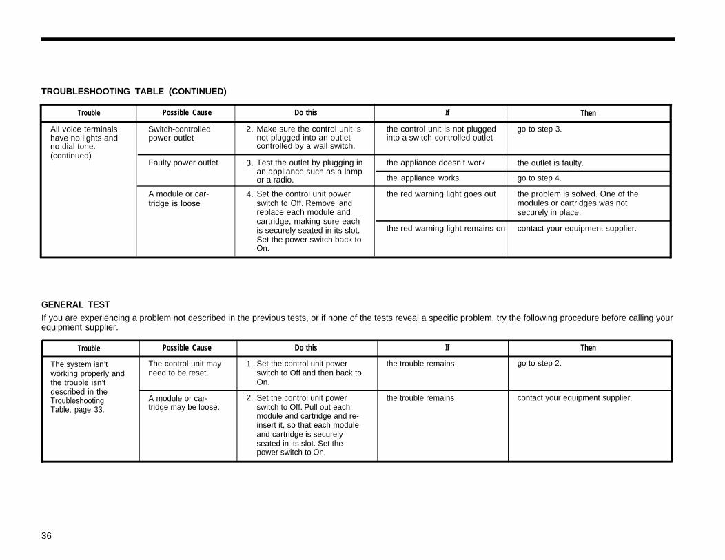
TROUBLESHOOTING TABLE (CONTINUED)
Trouble Possible Cause Do this If Then
All voice terminalshave no lights andno dial tone.(continued)
Switch-controlledpower outlet
2.
3.
4.
Faulty power outlet
A module or car-tridge is loose
Make sure the control unit isnot plugged into an outletcontrolled by a wall switch.
Test the outlet by plugging inan appliance such as a lampor a radio.
Set the control unit powerswitch to Off. Remove andreplace each module andcartridge, making sure eachis securely seated in its slot.Set the power switch back toOn.
the control unit is not plugged go to step 3.into a switch-controlled outlet
the appliance doesn’t work the outlet is faulty.
the appliance works go to step 4.
the red warning light goes out the problem is solved. One of themodules or cartridges was notsecurely in place.
the red warning light remains on contact your equipment supplier.
GENERAL TESTIf you are experiencing a problem not described in the previous tests, or if none of the tests reveal a specific problem, try the following procedure before calling yourequipment supplier.
Trouble Possible Cause Do this If Then
The system isn’t The control unit may 1. Set the control unit power the trouble remains go to step 2.working properly and need to be reset. switch to Off and then back tothe trouble isn’t On.described in theTroubleshooting A module or car- 2. Set the control unit power the trouble remains contact your equipment supplier.
Table, page 33. tridge may be loose. switch to Off. Pull out eachmodule and cartridge and re-insert it, so that each moduleand cartridge is securelyseated in its slot. Set thepower switch to On.
36
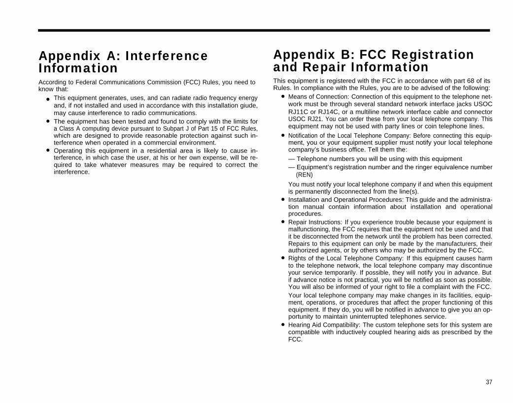
Appendix A: InterferenceInformationAccording to Federal Communications Commission (FCC) Rules, you need toknow that:
●
●
●
This equipment generates, uses, and can radiate radio frequency energyand, if not installed and used in accordance with this installation giude,may cause interference to radio communications.The equipment has been tested and found to comply with the limits fora Class A computing device pursuant to Subpart J of Part 15 of FCC Rules,which are designed to provide reasonable protection against such in-terference when operated in a commercial environment.Operating this equipment in a residential area is likely to cause in-terference, in which case the user, at his or her own expense, will be re-quired to take whatever measures may be required to correct theinterference.
Appendix B: FCC Registrationand Repair InformationThis equipment is registered with the FCC in accordance with part 68 of itsRules. In compliance with the Rules, you are to be advised of the following:
●
●
●
●
●
●
Means of Connection: Connection of this equipment to the telephone net-work must be through several standard network interface jacks USOCRJ11C or RJ14C, or a multiline network interface cable and connectorUSOC RJ21. You can order these from your local telephone company. Thisequipment may not be used with party lines or coin telephone lines.
Notification of the Local Telephone Company: Before connecting this equip-ment, you or your equipment supplier must notify your local telephonecompany’s business office. Tell them the:— Telephone numbers you will be using with this equipment— Equipment’s registration number and the ringer equivalence number
(REN)
You must notify your local telephone company if and when this equipmentis permanently disconnected from the line(s).Installation and Operational Procedures: This guide and the administra-tion manual contain information about installation and operationalprocedures.Repair Instructions: If you experience trouble because your equipment ismalfunctioning, the FCC requires that the equipment not be used and thatit be disconnected from the network until the problem has been corrected.Repairs to this equipment can only be made by the manufacturers, theirauthorized agents, or by others who may be authorized by the FCC.Rights of the Local Telephone Company: If this equipment causes harmto the telephone network, the local telephone company may discontinueyour service temporarily. If possible, they will notify you in advance. Butif advance notice is not practical, you will be notified as soon as possible.You will also be informed of your right to file a complaint with the FCC.Your local telephone company may make changes in its facilities, equip-ment, operations, or procedures that affect the proper functioning of thisequipment. If they do, you will be notified in advance to give you an op-portunity to maintain uninterrupted telephones service.Hearing Aid Compatibility: The custom telephone sets for this system arecompatible with inductively coupled hearing aids as prescribed by theFCC.
37
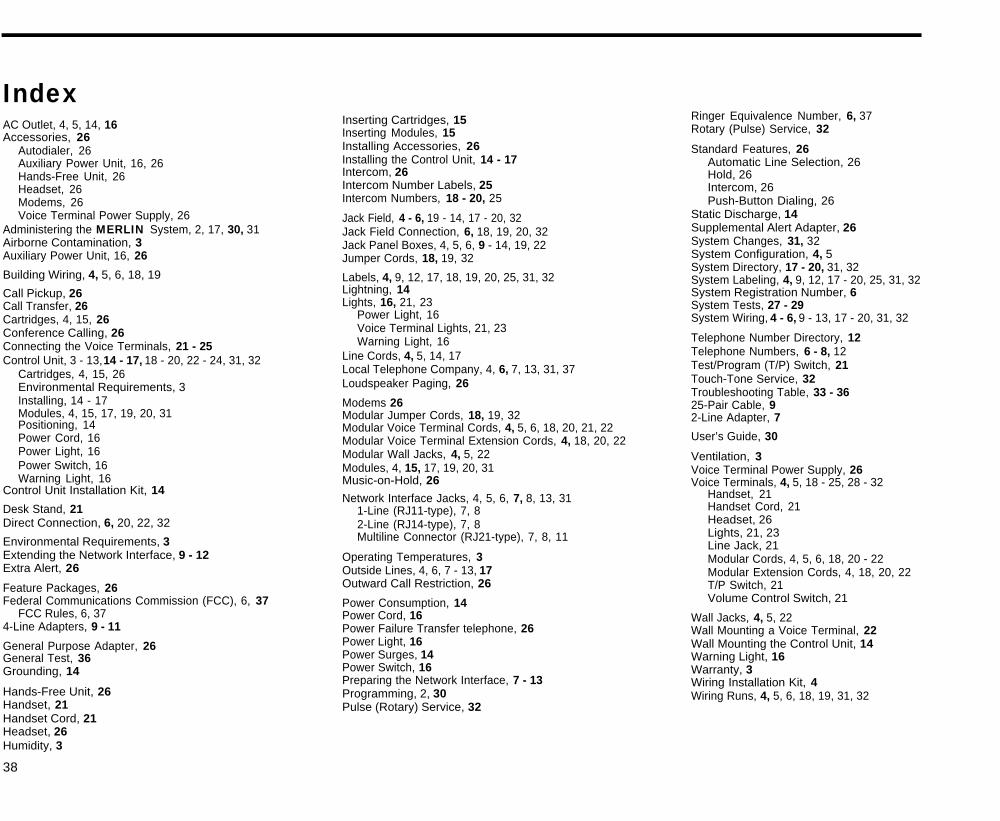
IndexAC Outlet, 4, 5, 14, 16Accessories, 26
Autodialer, 26Auxiliary Power Unit, 16, 26Hands-Free Unit, 26Headset, 26Modems, 26Voice Terminal Power Supply, 26
Administering the MERLIN System, 2, 17, 30, 31Airborne Contamination, 3Auxiliary Power Unit, 16, 26
Building Wiring, 4, 5, 6, 18, 19
Call Pickup, 26Call Transfer, 26Cartridges, 4, 15, 26Conference Calling, 26Connecting the Voice Terminals, 21 - 25Control Unit, 3 - 13, 14 - 17, 18 - 20, 22 - 24, 31, 32
Cartridges, 4, 15, 26Environmental Requirements, 3Installing, 14 - 17Modules, 4, 15, 17, 19, 20, 31Positioning, 14Power Cord, 16Power Light, 16Power Switch, 16Warning Light, 16
Control Unit Installation Kit, 14
Desk Stand, 21Direct Connection, 6, 20, 22, 32
Environmental Requirements, 3Extending the Network Interface, 9 - 12Extra Alert, 26
Feature Packages, 26Federal Communications Commission (FCC), 6, 37
FCC Rules, 6, 374-Line Adapters, 9 - 11
General Purpose Adapter, 26General Test, 36Grounding, 14
Hands-Free Unit, 26Handset, 21Handset Cord, 21Headset, 26Humidity, 3
38
Inserting Cartridges, 15Inserting Modules, 15Installing Accessories, 26Installing the Control Unit, 14 - 17Intercom, 26Intercom Number Labels, 25Intercom Numbers, 18 - 20, 25
Jack Field, 4 - 6, 19 - 14, 17 - 20, 32Jack Field Connection, 6, 18, 19, 20, 32Jack Panel Boxes, 4, 5, 6, 9 - 14, 19, 22Jumper Cords, 18, 19, 32
Labels, 4, 9, 12, 17, 18, 19, 20, 25, 31, 32Lightning, 14Lights, 16, 21, 23
Power Light, 16Voice Terminal Lights, 21, 23Warning Light, 16
Line Cords, 4, 5, 14, 17Local Telephone Company, 4, 6, 7, 13, 31, 37Loudspeaker Paging, 26
Modems 26Modular Jumper Cords, 18, 19, 32Modular Voice Terminal Cords, 4, 5, 6, 18, 20, 21, 22Modular Voice Terminal Extension Cords, 4, 18, 20, 22Modular Wall Jacks, 4, 5, 22Modules, 4, 15, 17, 19, 20, 31Music-on-Hold, 26
Network Interface Jacks, 4, 5, 6, 7, 8, 13, 311-Line (RJ11-type), 7, 82-Line (RJ14-type), 7, 8Multiline Connector (RJ21-type), 7, 8, 11
Operating Temperatures, 3Outside Lines, 4, 6, 7 - 13, 17Outward Call Restriction, 26
Power Consumption, 14Power Cord, 16Power Failure Transfer telephone, 26Power Light, 16Power Surges, 14Power Switch, 16Preparing the Network Interface, 7 - 13Programming, 2, 30Pulse (Rotary) Service, 32
Ringer Equivalence Number, 6, 37Rotary (Pulse) Service, 32
Standard Features, 26Automatic Line Selection, 26Hold, 26Intercom, 26Push-Button Dialing, 26
Static Discharge, 14Supplemental Alert Adapter, 26System Changes, 31, 32System Configuration, 4, 5System Directory, 17 - 20, 31, 32System Labeling, 4, 9, 12, 17 - 20, 25, 31, 32System Registration Number, 6System Tests, 27 - 29System Wiring, 4 - 6, 9 - 13, 17 - 20, 31, 32
Telephone Number Directory, 12Telephone Numbers, 6 - 8, 12Test/Program (T/P) Switch, 21Touch-Tone Service, 32Troubleshooting Table, 33 - 3625-Pair Cable, 92-Line Adapter, 7
User’s Guide, 30
Ventilation, 3Voice Terminal Power Supply, 26Voice Terminals, 4, 5, 18 - 25, 28 - 32
Handset, 21Handset Cord, 21Headset, 26Lights, 21, 23Line Jack, 21Modular Cords, 4, 5, 6, 18, 20 - 22Modular Extension Cords, 4, 18, 20, 22T/P Switch, 21Volume Control Switch, 21
Wall Jacks, 4, 5, 22Wall Mounting a Voice Terminal, 22Wall Mounting the Control Unit, 14Warning Light, 16Warranty, 3Wiring Installation Kit, 4Wiring Runs, 4, 5, 6, 18, 19, 31, 32

AT&T
MERLIN is a registered trademark of AT&T© Copyright 1986 AT&T. Printed in U.S.A.
518-600-010 ISIssue 3 July 1986