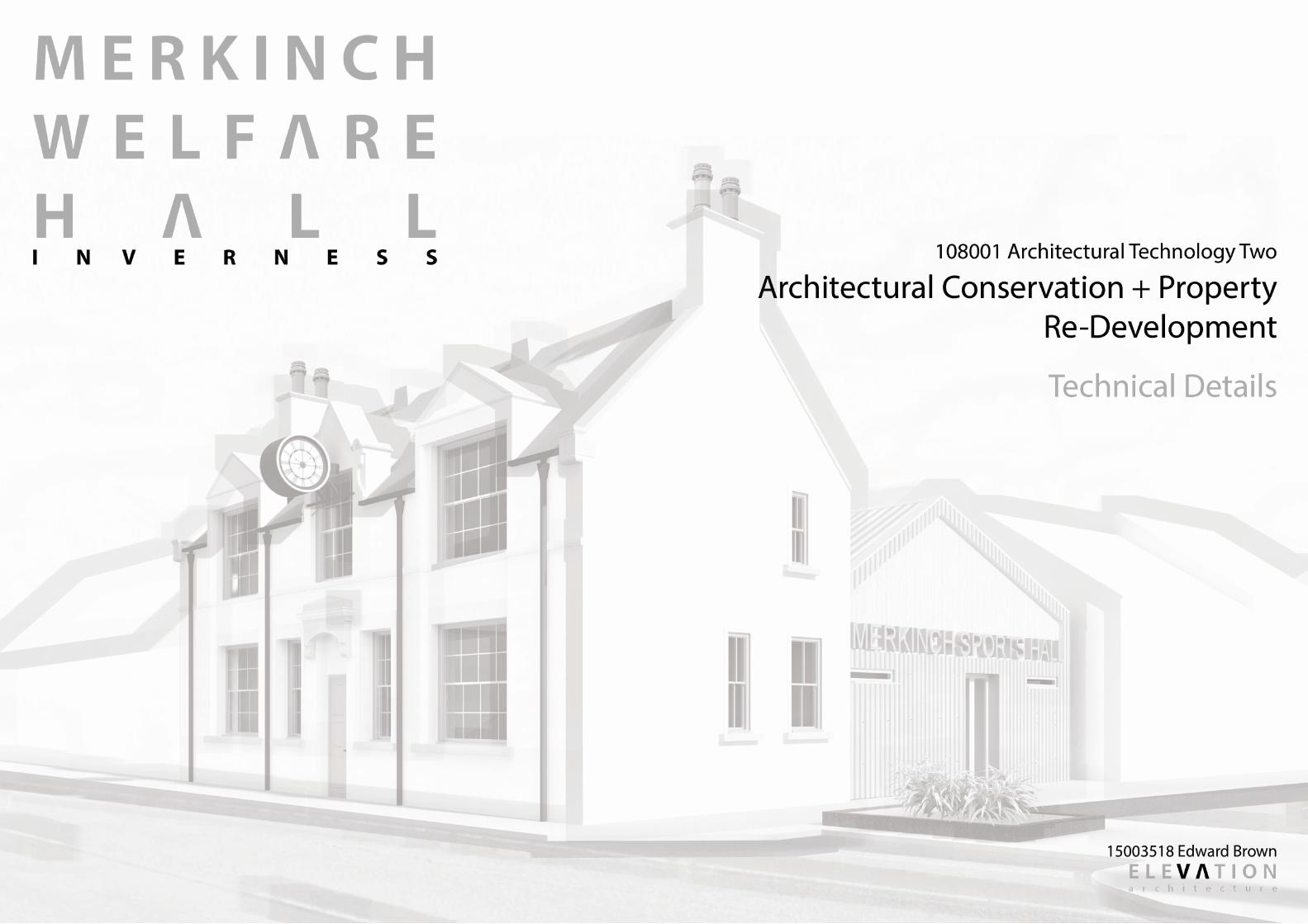
Merkinch Welfare Hall Technical Details
16
-
Upload
edward-brown -
Category
Design
-
view
24 -
download
1
Transcript of Merkinch Welfare Hall Technical Details


REVISIONS: DATE: DESCRIPTION:
DRAWING STATUS:
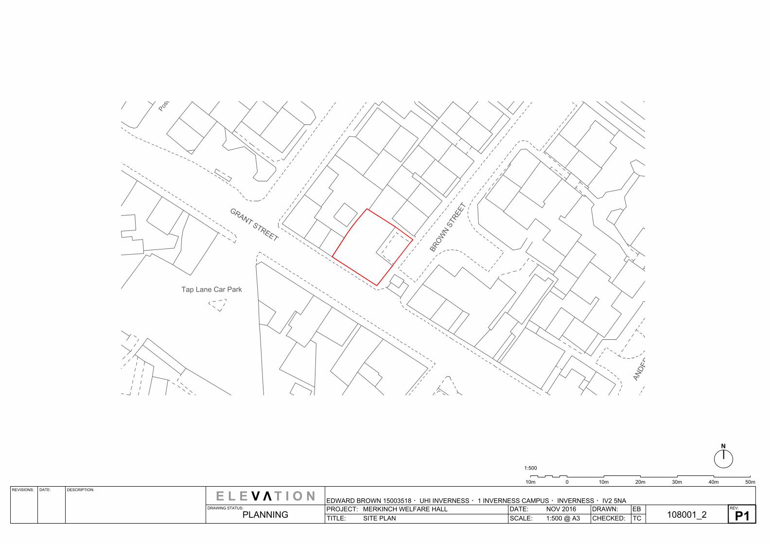
PROJECT: MERKINCH WELFARE HALL
TITLE: LOCATION PLAN
EDWARD BROWN 15003518 ・UHI INVERNESS ・1 INVERNESS CAMPUS ・INVERNESS ・IV2 5NAREV:
DATE: NOV 2016
SCALE: 1:2500 @ A3
DRAWN:
CHECKED: TC
EB
108001_1
P1
PLANNING
N
0 150m 250m100m 200m50m 50m
1:2500
E L E V T I O N
V
A
N
D
E
R
S
O
N
S
T
Tap Lane Car Park
P
o
s
t
s
G
R
A
N
T
S
T
R
E
E
T
B
R
O
W
N
S
T
R
E
E
T
REVISIONS: DATE: DESCRIPTION:
DRAWING STATUS:
PROJECT: MERKINCH WELFARE HALL
TITLE: SITE PLAN
EDWARD BROWN 15003518 ・UHI INVERNESS ・1 INVERNESS CAMPUS ・INVERNESS ・IV2 5NAREV:
DATE: NOV 2016
SCALE: 1:500 @ A3
DRAWN:
CHECKED: TC
EB
108001_2
P1
PLANNING
N
010m 10m 20m 30m 40m 50m
1:500
E L E V T I O N
V
REVISIONS: DATE: DESCRIPTION:
DRAWING STATUS:
PROJECT: MERKINCH WELFARE HALL
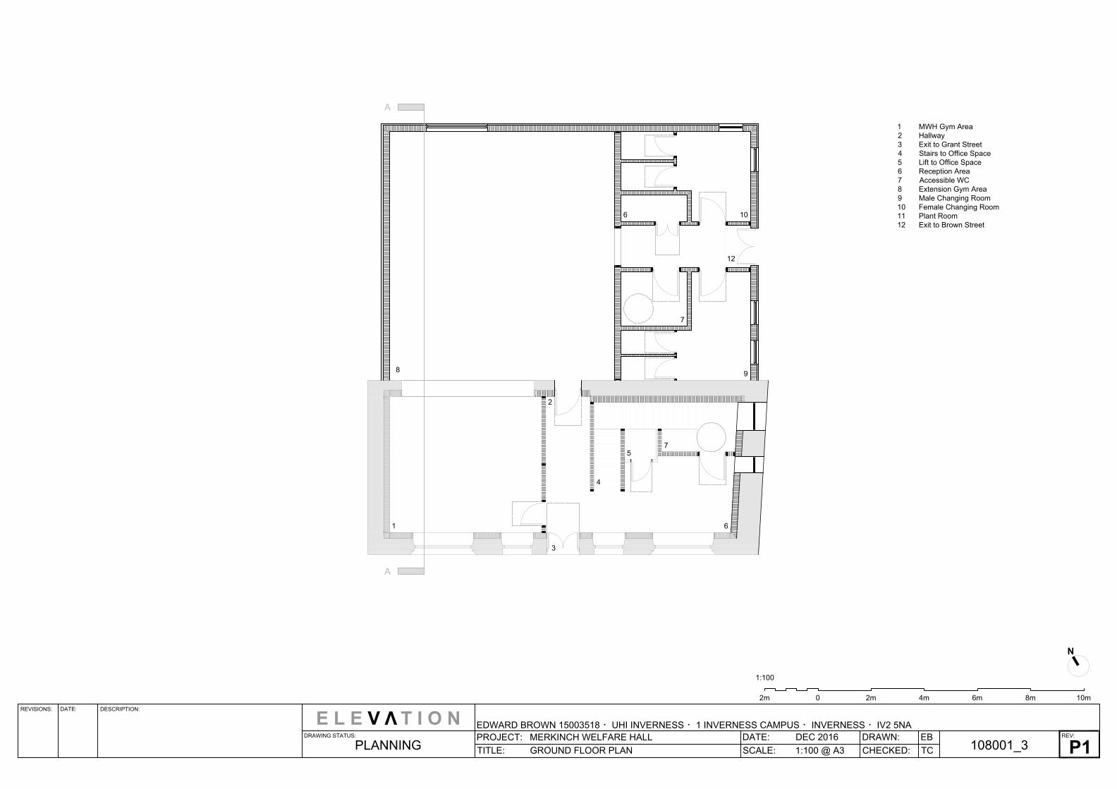
TITLE: GROUND FLOOR PLAN
E L E V T I O N
EDWARD BROWN 15003518 ・UHI INVERNESS ・1 INVERNESS CAMPUS ・INVERNESS ・IV2 5NAREV:
DATE: DEC 2016
SCALE: 1:100 @ A3
DRAWN:
CHECKED: TC
EB
108001_3
P1
PLANNING
V
02m 2m 4m 6m 8m 10m
1:100
N
A
A
1 MWH Gym Area
2 Hallway
3 Exit to Grant Street
4 Stairs to Office Space
5 Lift to Office Space
6 Reception Area
7 Accessible WC
8 Extension Gym Area
9 Male Changing Room
10 Female Changing Room
11 Plant Room
12 Exit to Brown Street
1
8
2
3
4
5
7
6
9
106
7
12
REVISIONS: DATE: DESCRIPTION:
DRAWING STATUS:
PROJECT: MERKINCH WELFARE HALL
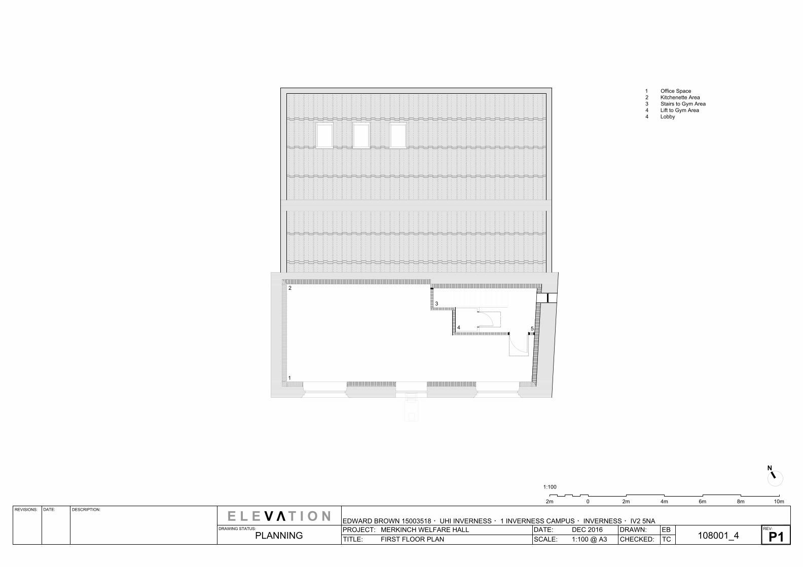
TITLE: FIRST FLOOR PLAN
E L E V T I O N
EDWARD BROWN 15003518 ・UHI INVERNESS ・1 INVERNESS CAMPUS ・INVERNESS ・IV2 5NAREV:
DATE: DEC 2016
SCALE: 1:100 @ A3
DRAWN:
CHECKED: TC
EB
108001_4
P1
PLANNING
V
02m 2m 4m 6m 8m 10m
1:100
N
1 Office Space
2 Kitchenette Area
3 Stairs to Gym Area
4 Lift to Gym Area
4 Lobby
1
2
3
4
5
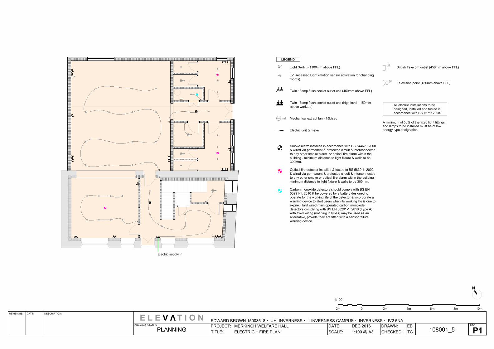
Light Switch (1100mm above FFL)
LV Recessed Light (motion sensor activation for changing
rooms)
Twin 13amp flush socket outlet unit (450mm above FFL)
Twin 13amp flush socket outlet unit (high level - 150mm
above worktop)
Mechanical extract fan - 15L/sec
Electric unit & meter
Smoke alarm installed in accordance with BS 5446-1: 2000
& wired via permanent & protected circuit & interconnected
to any other smoke alarm or optical fire alarm within the
building - minimum distance to light fixture & walls to be
300mm.
Optical fire detector installed & tested to BS 5839-1: 2002
& wired via permanent & protected circuit & interconnected
to any other smoke or optical fire alarm within the building -
minimum distance to light fixture & walls to be 300mm.
Carbon monoxide detectors should comply with BS EN
50291-1: 2010 & be powered by a battery designed to
operate for the working life of the detector & incorporate a
warning device to alert users when its working life is due to
expire. Hard wired main operated carbon monoxide
detectors complying with BS EN 50291-1: 2010 (Type A)
with fixed wiring (not plug in types) may be used as an
alternative, provide they are fitted with a sensor failure
warning device.
British Telecom outlet (450mm above FFL)
Television point (450mm above FFL)
All electric installations to be
designed, installed and tested in
accordance with BS 7671: 2008.
A minimum of 50% of the fixed light fittings
and lamps to be installed must be of low
energy type designation.
LEGEND
REVISIONS: DATE: DESCRIPTION:
DRAWING STATUS:
PROJECT: MERKINCH WELFARE HALL
TITLE: ELECTRIC + FIRE PLAN
E L E V T I O N
EDWARD BROWN 15003518 ・UHI INVERNESS ・1 INVERNESS CAMPUS ・INVERNESS ・IV2 5NAREV:
DATE: DEC 2016
SCALE: 1:100 @ A3
DRAWN:
CHECKED: TC
EB
108001_5
P1
PLANNING
V
02m 2m 4m 6m 8m 10m
1:100
N
Electric supply in
AutoCAD SHX Text
mef
AutoCAD SHX Text
mef
AutoCAD SHX Text
mef
AutoCAD SHX Text
mef
AutoCAD SHX Text
BT
AutoCAD SHX Text
TV
AutoCAD SHX Text
TV
AutoCAD SHX Text
BT
AutoCAD SHX Text
mef
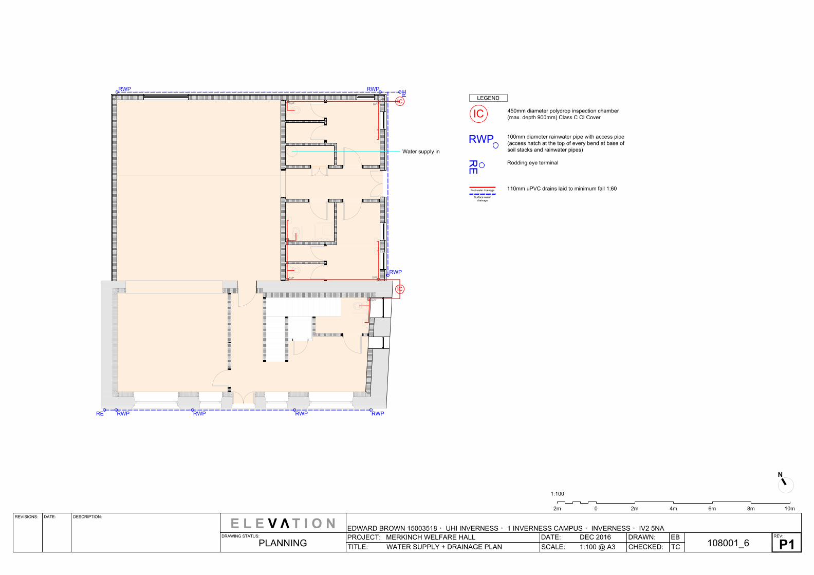
450mm diameter polydrop inspection chamber
(max. depth 900mm) Class C CI Cover
100mm diameter rainwater pipe with access pipe
(access hatch at the top of every bend at base of
soil stacks and rainwater pipes)
Rodding eye terminal
110mm uPVC drains laid to minimum fall 1:60
LEGEND
RWPRWP
RWP
RWPRWP RWP RWP
SVP
SVP
SVP
SVP
SVP
SVP
IC
RE
RE
RE
IC
IC
RWP
Foul water drainage
Surface water
drainage
REVISIONS: DATE: DESCRIPTION:
DRAWING STATUS:
PROJECT: MERKINCH WELFARE HALL
TITLE: WATER SUPPLY + DRAINAGE PLAN
E L E V T I O N
EDWARD BROWN 15003518 ・UHI INVERNESS ・1 INVERNESS CAMPUS ・INVERNESS ・IV2 5NAREV:
DATE: DEC 2016
SCALE: 1:100 @ A3
DRAWN:
CHECKED: TC
EB
108001_6
P1
PLANNING
V
02m 2m 4m 6m 8m 10m
1:100
N
Water supply in
REVISIONS: DATE: DESCRIPTION:
DRAWING STATUS:
PROJECT: MERKINCH WELFARE HALL
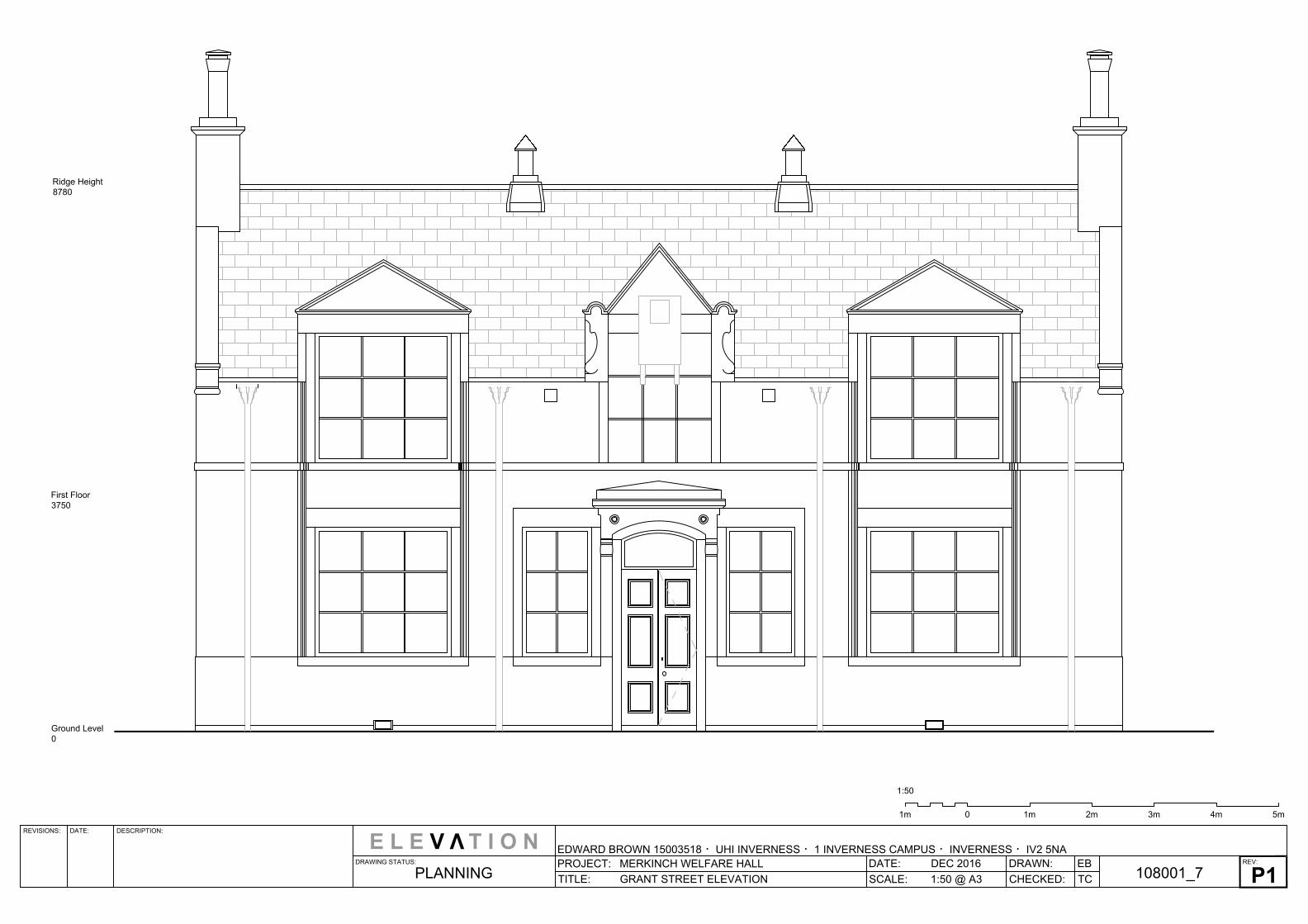
TITLE: GRANT STREET ELEVATION
E L E V T I O N
EDWARD BROWN 15003518 ・UHI INVERNESS ・1 INVERNESS CAMPUS ・INVERNESS ・IV2 5NAREV:
DATE: DEC 2016
SCALE: 1:50 @ A3
DRAWN:
CHECKED: TC
EB
108001_7
P1
PLANNING
V
0 1m 2m 3m 4m 5m1m
1:50
Ground Level
0
First Floor
3750
Ridge Height
8780
REVISIONS: DATE: DESCRIPTION:
DRAWING STATUS:
PROJECT: MERKINCH WELFARE HALL
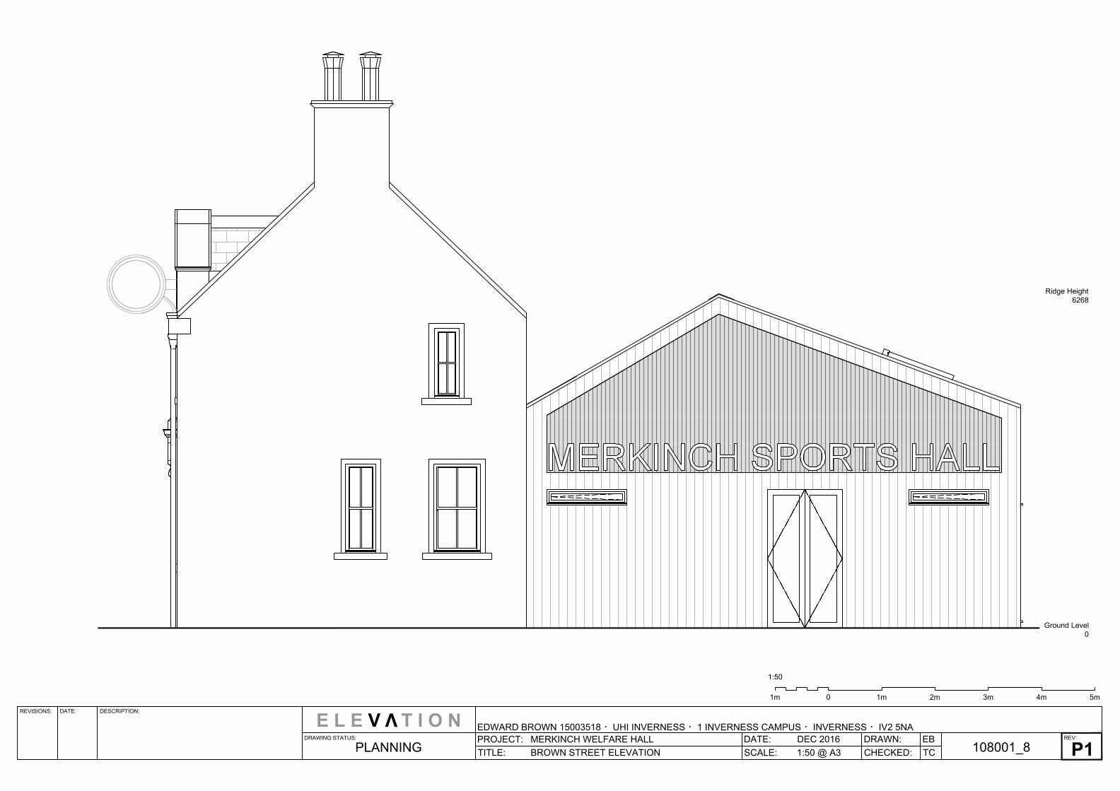
TITLE: BROWN STREET ELEVATION
E L E V T I O N
EDWARD BROWN 15003518 ・UHI INVERNESS ・1 INVERNESS CAMPUS ・INVERNESS ・IV2 5NAREV:
DATE: DEC 2016
SCALE: 1:50 @ A3
DRAWN:
CHECKED: TC
EB
108001_8
P1
PLANNING
V
0 1m 2m 3m 4m 5m1m
1:50
Ground Level
0
Ridge Height
6268
REVISIONS: DATE: DESCRIPTION:
DRAWING STATUS:
PROJECT: MERKINCH WELFARE HALL
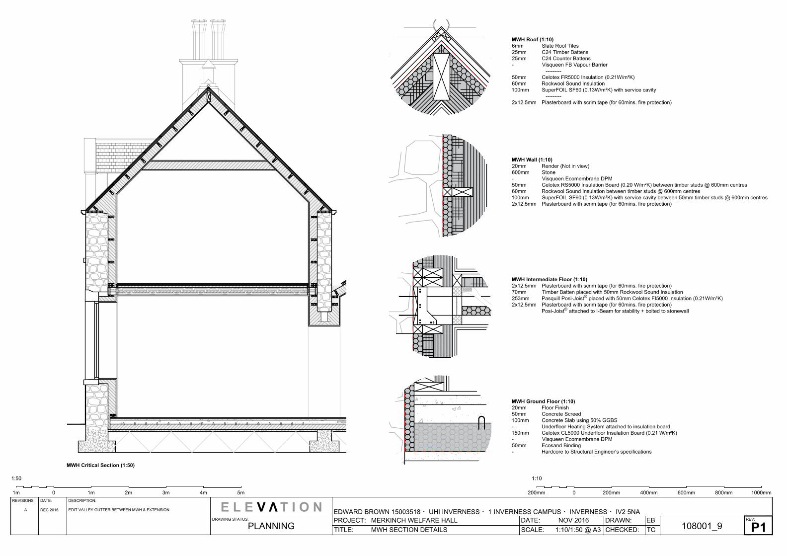
TITLE: MWH SECTION DETAILS
E L E V T I O N
EDWARD BROWN 15003518 ・UHI INVERNESS ・1 INVERNESS CAMPUS ・INVERNESS ・IV2 5NAREV:
DATE: NOV 2016
SCALE: 1:10/1:50 @ A3
DRAWN:
CHECKED: TC
EB
108001_9
P1
PLANNING
0 1m 2m 3m 4m 5m1m
1:50
V
MWH Roof (1:10)
6mm Slate Roof Tiles
25mm C24 Timber Battens
25mm C24 Counter Battens
- Visqueen FB Vapour Barrier
---------
50mm Celotex FR5000 Insulation (0.21W/m²K)
60mm Rockwool Sound Insulation
100mm SuperFOIL SF60 (0.13W/m²K) with service cavity
---------
2x12.5mm Plasterboard with scrim tape (for 60mins. fire protection)
MWH Ground Floor (1:10)
20mm Floor Finish
50mm Concrete Screed
100mm Concrete Slab using 50% GGBS
- Underfloor Heating System attached to insulation board
150mm Celotex CL5000 Underfloor Insulation Board (0.21 W/m²K)
- Visqueen Ecomembrane DPM
50mm Ecosand Binding
- Hardcore to Structural Engineer's specifications
MWH Wall (1:10)
20mm Render (Not in view)
600mm Stone
- Visqueen Ecomembrane DPM
50mm Celotex RS5000 Insulation Board (0.20 W/m²K) between timber studs @ 600mm centres
60mm Rockwool Sound Insulation between timber studs @ 600mm centres
100mm SuperFOIL SF60 (0.13W/m²K) with service cavity between 50mm timber studs @ 600mm centres
2x12.5mm Plasterboard with scrim tape (for 60mins. fire protection)
MWH Intermediate Floor (1:10)
2x12.5mm Plasterboard with scrim tape (for 60mins. fire protection)
70mm Timber Batten placed with 50mm Rockwool Sound Insulation
253mm Pasquill Posi-Joist
®
placed with 50mm Celotex FI5000 Insulation (0.21W/m²K)
2x12.5mm Plasterboard with scrim tape (for 60mins. fire protection)
Posi-Joist
®
attached to I-Beam for stability + bolted to stonewall
0 1000mm800mm600mm400mm200mm200mm
1:10
MWH Critical Section (1:50)
A DEC 2016EDIT VALLEY GUTTER BETWEEN MWH & EXTENSION
REVISIONS: DATE: DESCRIPTION:
DRAWING STATUS:
PROJECT: MERKINCH WELFARE HALL
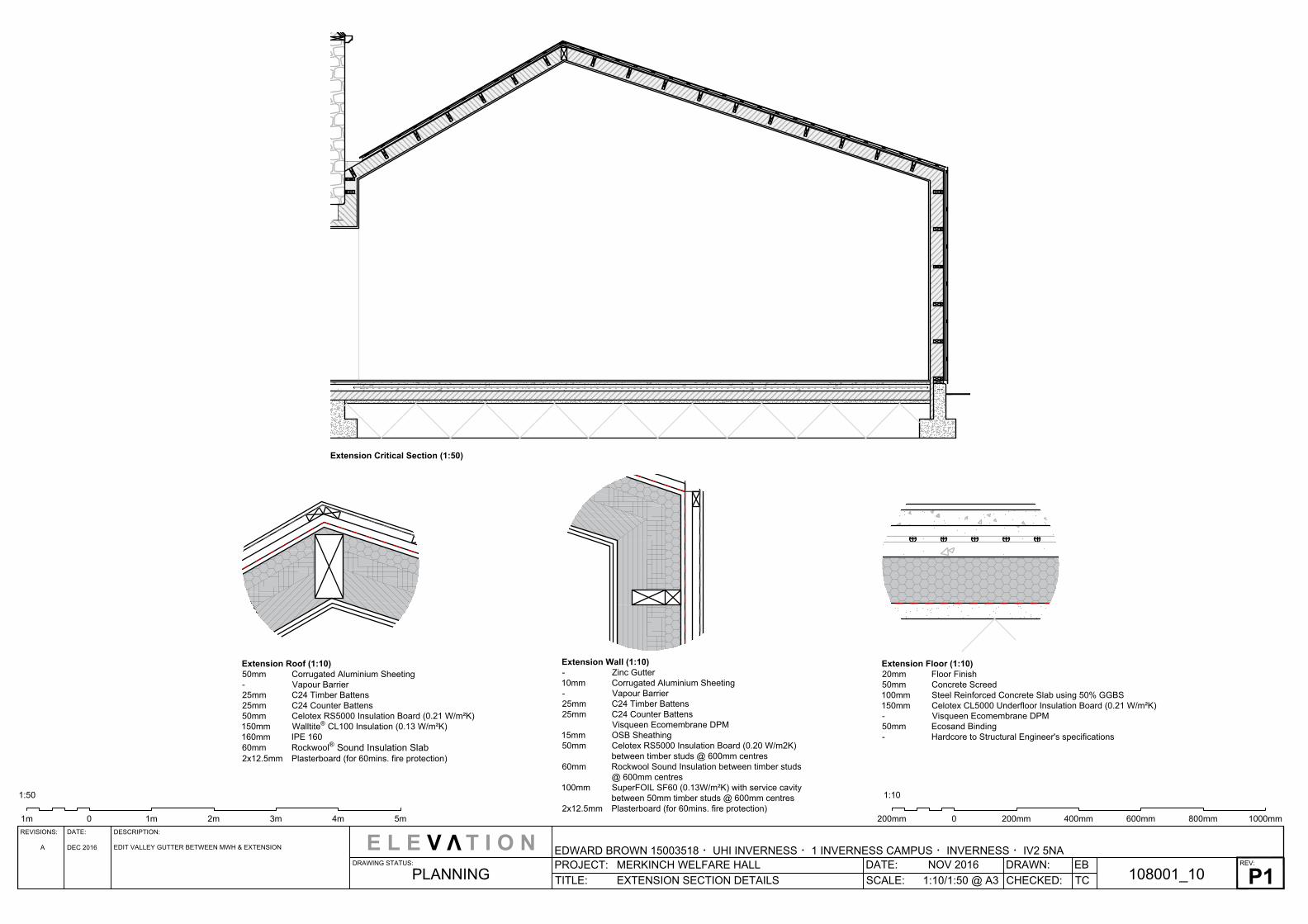
TITLE: EXTENSION SECTION DETAILS
E L E V T I O N
EDWARD BROWN 15003518 ・UHI INVERNESS ・1 INVERNESS CAMPUS ・INVERNESS ・IV2 5NAREV:
DATE: NOV 2016
SCALE: 1:10/1:50 @ A3
DRAWN:
CHECKED: TC
EB
108001_10
P1
PLANNING
0 1m 2m 3m 4m 5m1m
1:50
V
Extension Roof (1:10)
50mm Corrugated Aluminium Sheeting
- Vapour Barrier
25mm C24 Timber Battens
25mm C24 Counter Battens
50mm Celotex RS5000 Insulation Board (0.21 W/m²K)
150mm Walltite
®
CL100 Insulation (0.13 W/m²K)
160mm IPE 160
60mm Rockwool
®
Sound Insulation Slab
2x12.5mm Plasterboard (for 60mins. fire protection)
Extension Wall (1:10)
- Zinc Gutter
10mm Corrugated Aluminium Sheeting
- Vapour Barrier
25mm C24 Timber Battens
25mm C24 Counter Battens
Visqueen Ecomembrane DPM
15mm OSB Sheathing
50mm Celotex RS5000 Insulation Board (0.20 W/m2K)
between timber studs @ 600mm centres
60mm Rockwool Sound Insulation between timber studs
@ 600mm centres
100mm SuperFOIL SF60 (0.13W/m²K) with service cavity
between 50mm timber studs @ 600mm centres
2x12.5mm Plasterboard (for 60mins. fire protection)
Extension Floor (1:10)
20mm Floor Finish
50mm Concrete Screed
100mm Steel Reinforced Concrete Slab using 50% GGBS
150mm Celotex CL5000 Underfloor Insulation Board (0.21 W/m²K)
- Visqueen Ecomembrane DPM
50mm Ecosand Binding
- Hardcore to Structural Engineer's specifications
0 1000mm800mm600mm400mm200mm200mm
1:10
Extension Critical Section (1:50)
A DEC 2016EDIT VALLEY GUTTER BETWEEN MWH & EXTENSION
REVISIONS: DATE: DESCRIPTION:
DRAWING STATUS:
PROJECT: MERKINCH WELFARE HALL
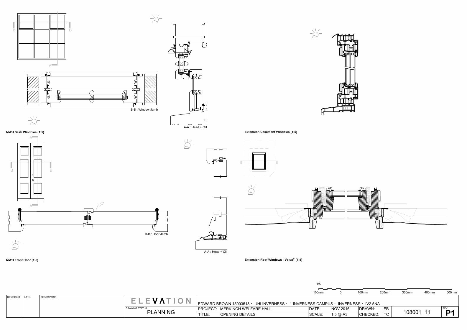
TITLE: OPENING DETAILS
E L E V T I O N
EDWARD BROWN 15003518 ・UHI INVERNESS ・1 INVERNESS CAMPUS ・INVERNESS ・IV2 5NAREV:
DATE: NOV 2016
SCALE: 1:5 @ A3
DRAWN:
CHECKED: TC
EB
108001_11
P1
PLANNING
V
0 500mm100mm 200mm 300mm 400mm100mm
1:5
MWH Sash Windows (1:5)
B-B : Window Jamb
A-A : Head + Cill
A
B B
MWH Front Door (1:5)
B-B : Door Jamb
A-A : Head + Cill
A
A
B B
Extension Casement Windows (1:5)
Extension Roof Windows - Velux
®
(1:5)

REVISIONS: DATE: DESCRIPTION:
DRAWING STATUS:
PROJECT: MERKINCH WELFARE HALL
TITLE: THERMAL BRIDGING + AIR TIGHTNESS
E L E V T I O N
EDWARD BROWN 15003518 ・UHI INVERNESS ・1 INVERNESS CAMPUS ・INVERNESS ・IV2 5NAREV:
DATE: NOV 2016
SCALE: 1:100 @ A3
DRAWN:
CHECKED: TC
EB
108001_12
P1
PLANNING
V
Thermal Bridging
Junctions and connections within a building envelope can typically provide a
route for heat loss, which must be reduced, or if possible, eliminated. The
diagram opposite illustrates common areas in a building where thermal bridging
may occur. Careful design and implementation is required to ensure that these
particular areas do not create unnecessary heat loss paths.
The proposed design aims to reduce thermal bridging in the building. The
insulation is added in response to avoid any penetration from external weather
and prevent heat loss internally. It is important to focus in extending the
insulation around the MWH in the roof, walls, and floor to prevent any heat loss
from the building.
Air Tightness
A high level of air tightness within the building reduces the heating demand and
prevents moisture-laden air from entering the fabric. Achieving air tightness can
be achieved by using airtight membranes/barriers within the building elements
such as a vapour barrier layer. Where layers could be interrupted, like windows,
propriety tape can be attached to the barrier layer ensuring that around
openings continue to be air tight.
Ensuring the building envelope is air tight to reduce the risk of structural
damage, careful design and installation of components such as windows and
doors is imperative. It is aimed to not allow air to flow randomly through walls of
the envelope. This is important because changing temperatures of air flow is not
sufficient to provide consistently air quality for both the occupant and the
building itself. Poor acoustic insulation and heat loss are further disadvantages.
A new ventilation system and acoustic insulation is added to the
extension/sports hall.
02m 2m 4m 6m 8m 10m
1:100