
Mercury Install Man 1
106
Installation and Maintenance Manual for the CONVERSip MP5000 Media Platform Volume 1 - Introduction, Features, and Specifications
Transcript of Mercury Install Man 1
Installation and Maintenance Manualfor the CONVERSip MP5000 Media Platform
Volume 1 - Introduction, Features, and Specifications
Comdial strives to design the features in our communications systems to be fully interactive with one another. However, this is not always possible, as the combinations of accessories and features are too varied and extensive to insure total feature compatibility.
Accordingly, some features identified in this publication will not operate if some other feature is activated, Comdial disclaims all liability relating to feature non-compatibility or associated in any way with problems which may be encountered by incompatible features. Notwithstanding anything contained in this publication to the contrary, Comdial makes no representation herein as to the compatibility of features.
Issued 03/04
Copyright © 2003 Comdial CorporationAll rights reserved. Unauthorized use of this document is prohibited.
Comdial Corporation106 Cattlemen Road, Sarasota, FL 34232
-Notice-Comdial reserves the right to make any changes and improvements in the product described in
this document oat any time and without prior notice.
CONVERSip is a trademark of Comdial Corporation. All other product names are trademarks of their respective owners.
Table of Contents
1. Introducing the CONVERSip MP5000 Multimedia Platform ........................................................ 1
1.1 Using This Manual ................................................................................................................... 1
1.2 Using Related Publications ...................................................................................................... 11.2.1 Locating Documentation ................................................................................................. 2
1.3 Overview .................................................................................................................................. 31.3.1 System Components ...................................................................................................... 31.3.2 How the System Works .................................................................................................. 3
Understanding SIP......................................................................................................... 3
1.4 Supported Comdial Telephones............................................................................................... 5
1.5 Understanding the Telephone Features................................................................................... 7
1.6 Understanding the System Components and Product Codes.................................................. 9
1.7 System Specifications ............................................................................................................ 10
2. Understanding the System Features .......................................................................................... 13
2.1 Feature Listing ....................................................................................................................... 13
3. Describing the Hardware ............................................................................................................. 79
3.1 Main/Expansion Cabinet (FXCBX-II)...................................................................................... 793.1.1 Central Processor Board (FXCPU-3) ........................................................................... 80
Status Indicators .......................................................................................................... 81Programming Requirements ........................................................................................ 81
3.1.2 FXCPU3 Memory Upgrades ......................................................................................... 813.1.3 Services Board (FXSRV2-II or FXSRV-EX) ................................................................. 833.1.4 External Battery Assembly (BBLFXII) ........................................................................... 833.1.5 Auxiliary board (FXINT-MAUXII) .................................................................................. 843.1.6 Ribbon Cable Expansion Kit (FXII-RBNEXP) ............................................................... 843.1.7 SCSI Expansion Kits (FXII-EXP) .................................................................................. 843.1.8 Fiber Optics Expansion Kits (FXOPX-n) ...................................................................... 853.1.9 Line and Station Boards Overview ............................................................................... 863.1.10 Digital Station Board (FXLDS-16) ............................................................................... 873.1.11 Loop/Ground Start CO Line Board (FXGST-08) ......................................................... 873.1.12 Centrex Message Waiting Line Board w/CID (FXCMW-xx) ....................................... 883.1.13 DID/E&M Line Board (FXEMDD-DF) .......................................................................... 883.1.14 T1 Line Board (FXT1-24) ............................................................................................ 883.1.15 FXNET Board (FXNET) .............................................................................................. 893.1.16 Synchronization Card (DXOPT-SYN) ......................................................................... 893.1.17 ISDN-PRI Interface Line Board (FXT1-PRI) ............................................................... 893.1.18 IST Station Board (FXISTM-Cxx) ............................................................................... 90
i

3.1.19 VoIP Line Board (FXVoIP-x) ....................................................................................... 91Protocols and Features................................................................................................ 92Programming Requirements ........................................................................................ 92SIP Endpoints .............................................................................................................. 93Soft Phone ................................................................................................................... 948902-P IP Telephone ................................................................................................... 94
3.1.20 DTMF Receiver Board (FXDTMF-xx) ......................................................................... 943.1.21 DTMF Receiver Card (DXOPT-TON) ......................................................................... 94
ii

Revision History
Version Changes Date
01 Initial Release 09/03
iii

This page intentionally left blank
iv
MP5000 I&M Manual - Volume 1
1. INTRODUCING THE CONVERSIP MP5000 MULTIMEDIA PLATFORM
1.1 Using This Manual
This publication contains a technical discussion of the digital telephone system. It provides step-by-step instructions for installation and programming. You should become familiar with this manual before you attempt to install and program the system. This manual is comprised of three separate volumes, numbered and arranged as follows:
Volume 1: IMI89365 - Introduction and Features
• Chapter 1, Introduction, is a general overview of the system components and part numbers. Also included is a listing of related publications and general system specifications.
• Chapter 2, Feature Description, provides a description of all station and system features associated with Comdial’s CONVERSip MP5000.
• Chapter 3, Hardware Description, provides an understanding of the operational characteristics of the system hardware components.
Volume 2: IMI89366- Installation
• Chapter 4, Installation, provides instructions for installing the cabinet, printed circuit boards, and ancillary equipment.
Volume 3: IMI89367- Programming and Maintenance
• Chapter 5, Programming, provides instructions for programming the various operational characteristics of the system.
• Chapter 6, Records, provide templates for recording the site specific programming.
• Chapter 7, Maintenance, provides assistance in resolving system or sub-assembly failures.
• Appendix A, SIP Administration, provides an overview of a SIP installation.
1.2 Using Related Publications
All of the Comdial publications are available for download from Comdial’s Customer Care Center, located at http://www.comdial.com/ccc. Should you need hard copies of these publications, contact your Comdial inside sales representative.
ComdialInside Sales Department106 Cattlemen RoadSarasota, Florida 34232
Phone: 1800-Comdial
June 2003 Comdial 5
Introducing the CONVERSip MP5000 Multimedia Platform
1.2.1 LOCATING DOCUMENTATION
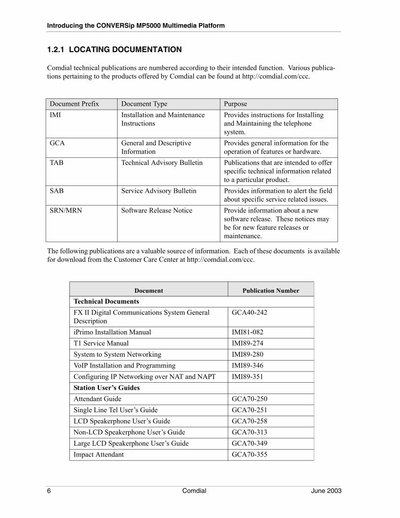
Comdial technical publications are numbered according to their intended function. Various publica-tions pertaining to the products offered by Comdial can be found at http://comdial.com/ccc.
The following publications are a valuable source of information. Each of these documents is available for download from the Customer Care Center at http://comdial.com/ccc.
Document Prefix Document Type PurposeIMI Installation and Maintenance
InstructionsProvides instructions for Installing and Maintaining the telephone system.
GCA General and Descriptive Information
Provides general information for the operation of features or hardware.
TAB Technical Advisory Bulletin Publications that are intended to offer specific technical information related to a particular product.
SAB Service Advisory Bulletin Provides information to alert the field about specific service related issues.
SRN/MRN Software Release Notice Provide information about a new software release. These notices may be for new feature releases or maintenance.
Document Publication Number
Technical DocumentsFX II Digital Communications System General Description
GCA40-242
iPrimo Installation Manual IMI81-082T1 Service Manual IMI89-274System to System Networking IMI89-280VoIP Installation and Programming IMI89-346Configuring IP Networking over NAT and NAPT IMI89-351Station User’s GuidesAttendant Guide GCA70-250Single Line Tel User’s Guide GCA70-251LCD Speakerphone User’s Guide GCA70-258Non-LCD Speakerphone User’s Guide GCA70-313Large LCD Speakerphone User’s Guide GCA70-349Impact Attendant GCA70-355
6 Comdial June 2003
MP5000 I&M Manual - Volume 1
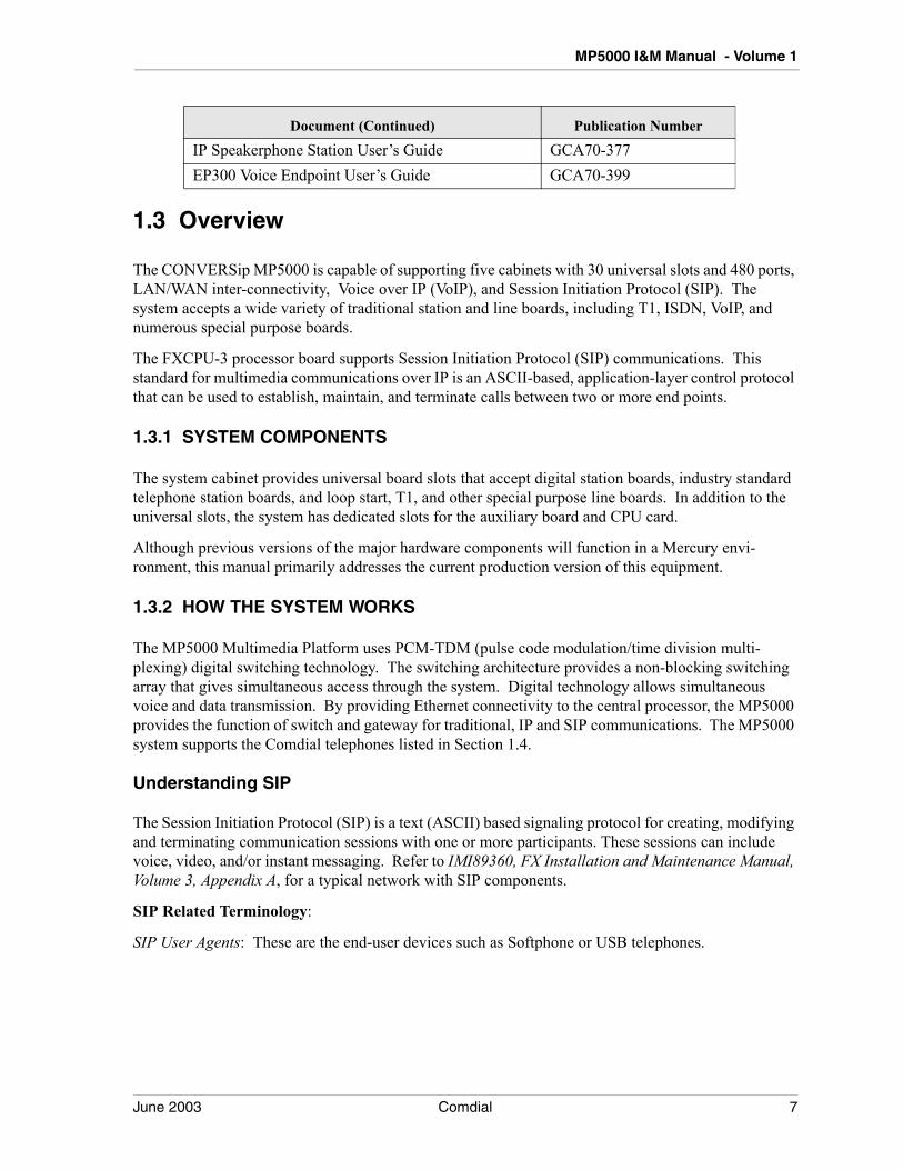
1.3 Overview
The CONVERSip MP5000 is capable of supporting five cabinets with 30 universal slots and 480 ports, LAN/WAN inter-connectivity, Voice over IP (VoIP), and Session Initiation Protocol (SIP). The system accepts a wide variety of traditional station and line boards, including T1, ISDN, VoIP, and numerous special purpose boards.
The FXCPU-3 processor board supports Session Initiation Protocol (SIP) communications. This standard for multimedia communications over IP is an ASCII-based, application-layer control protocol that can be used to establish, maintain, and terminate calls between two or more end points.
1.3.1 SYSTEM COMPONENTS
The system cabinet provides universal board slots that accept digital station boards, industry standard telephone station boards, and loop start, T1, and other special purpose line boards. In addition to the universal slots, the system has dedicated slots for the auxiliary board and CPU card.
Although previous versions of the major hardware components will function in a Mercury envi-ronment, this manual primarily addresses the current production version of this equipment.
1.3.2 HOW THE SYSTEM WORKS
The MP5000 Multimedia Platform uses PCM-TDM (pulse code modulation/time division multi-plexing) digital switching technology. The switching architecture provides a non-blocking switching array that gives simultaneous access through the system. Digital technology allows simultaneous voice and data transmission. By providing Ethernet connectivity to the central processor, the MP5000 provides the function of switch and gateway for traditional, IP and SIP communications. The MP5000 system supports the Comdial telephones listed in Section 1.4.
Understanding SIP
The Session Initiation Protocol (SIP) is a text (ASCII) based signaling protocol for creating, modifying and terminating communication sessions with one or more participants. These sessions can include voice, video, and/or instant messaging. Refer to IMI89360, FX Installation and Maintenance Manual, Volume 3, Appendix A, for a typical network with SIP components.
SIP Related Terminology:
SIP User Agents: These are the end-user devices such as Softphone or USB telephones.
IP Speakerphone Station User’s Guide GCA70-377EP300 Voice Endpoint User’s Guide GCA70-399
Document (Continued) Publication Number
June 2003 Comdial 7

Introducing the CONVERSip MP5000 Multimedia Platform
Registrar Server: The SIP Registrar is responsible for registering all the SIP telephones in a SIP system. The act of registration allows a SIP telephone to logon to the system by providing the end-user’s credentials (user name or extension, and password), as well as the IP addresses or SIP addresses where the end-user can be contacted. Registration allows calls to be routed to where an end-user is logged on, instead of a fixed port as in a traditional system. The FX CPU-III fulfills the role of the Registrar Server.
Proxy Server: A SIP Proxy is responsible for call setup, routing, control, and tear down. The SIP Proxy is the basic SIP call processing engine in a SIP system. Requests made by a SIP user agent are sent to the Proxy Server. This server then queries the Registrar Server to obtain the recipients addressing information. It then forwards the request to the recipient user agent. The FX CPU-III also serves as the Proxy Server.
SIP provides the following capabilities:
• Determine the location of the target participants. This is made possible by the entries made in VMMI programming and being logged into the network.
• Determine the media capabilities of the target end point. Calls are established using only the media capabilities that can be supported by all end points. That is, if a video call is being placed by a user, the far-end must also have video capability before that portion of the session is allowed.
• Establish a session between the originating and target end point. The current session types include voice, video, and instant messaging.
• SIP supports the transfer of calls from one end point to another. During a call transfer, SIP establishes a session with the new end point and terminates the session with the previous end point. At the end of the call, SIP terminates the sessions between all parties.
Refer to IMI89360, Volume 3, Appendix A, for a detailed description of SIP call setup, protocol message exchange, and LAN/WAN inter-connectivity.
Note: Some features associated with Comdial’s proprietary digital telephones are not sup-ported by the SIP protocol, and are not available for use with SIP telephones.
8 Comdial June 2003
MP5000 I&M Manual - Volume 1
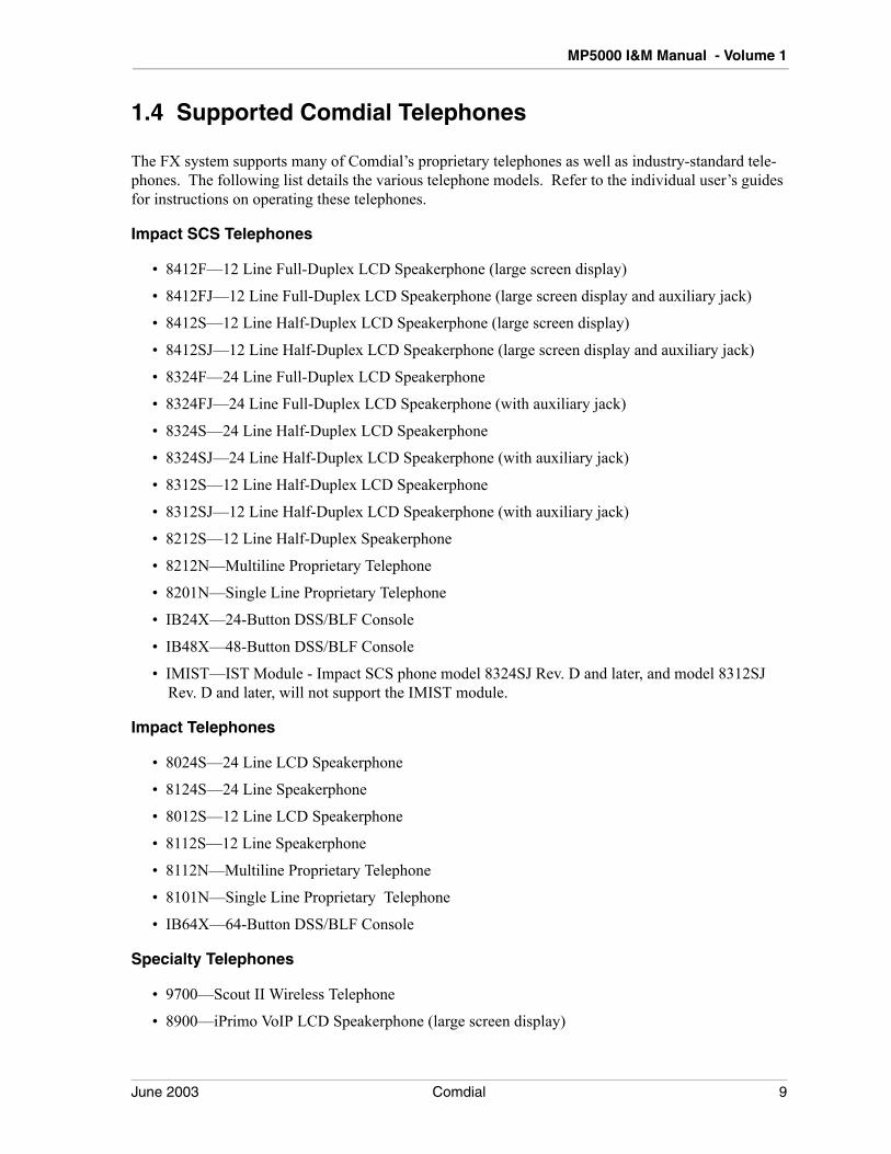
1.4 Supported Comdial Telephones
The FX system supports many of Comdial’s proprietary telephones as well as industry-standard tele-phones. The following list details the various telephone models. Refer to the individual user’s guides for instructions on operating these telephones.
Impact SCS Telephones
• 8412F—12 Line Full-Duplex LCD Speakerphone (large screen display)
• 8412FJ—12 Line Full-Duplex LCD Speakerphone (large screen display and auxiliary jack)
• 8412S—12 Line Half-Duplex LCD Speakerphone (large screen display)
• 8412SJ—12 Line Half-Duplex LCD Speakerphone (large screen display and auxiliary jack)
• 8324F—24 Line Full-Duplex LCD Speakerphone
• 8324FJ—24 Line Full-Duplex LCD Speakerphone (with auxiliary jack)
• 8324S—24 Line Half-Duplex LCD Speakerphone
• 8324SJ—24 Line Half-Duplex LCD Speakerphone (with auxiliary jack)
• 8312S—12 Line Half-Duplex LCD Speakerphone
• 8312SJ—12 Line Half-Duplex LCD Speakerphone (with auxiliary jack)
• 8212S—12 Line Half-Duplex Speakerphone
• 8212N—Multiline Proprietary Telephone
• 8201N—Single Line Proprietary Telephone
• IB24X—24-Button DSS/BLF Console
• IB48X—48-Button DSS/BLF Console
• IMIST—IST Module - Impact SCS phone model 8324SJ Rev. D and later, and model 8312SJ Rev. D and later, will not support the IMIST module.
Impact Telephones
• 8024S—24 Line LCD Speakerphone
• 8124S—24 Line Speakerphone
• 8012S—12 Line LCD Speakerphone
• 8112S—12 Line Speakerphone
• 8112N—Multiline Proprietary Telephone
• 8101N—Single Line Proprietary Telephone
• IB64X—64-Button DSS/BLF Console
Specialty Telephones
• 9700—Scout II Wireless Telephone
• 8900—iPrimo VoIP LCD Speakerphone (large screen display)
June 2003 Comdial 9

Introducing the CONVERSip MP5000 Multimedia Platform
• 8902-IP—CONVERSip EP300 - 24 Button Multimedia Endpoint Telephone
• 8904—CONVERSip EP200 Multimedia Endpoint - Soft Phone
10 Comdial June 2003
MP5000 I&M Manual - Volume 1
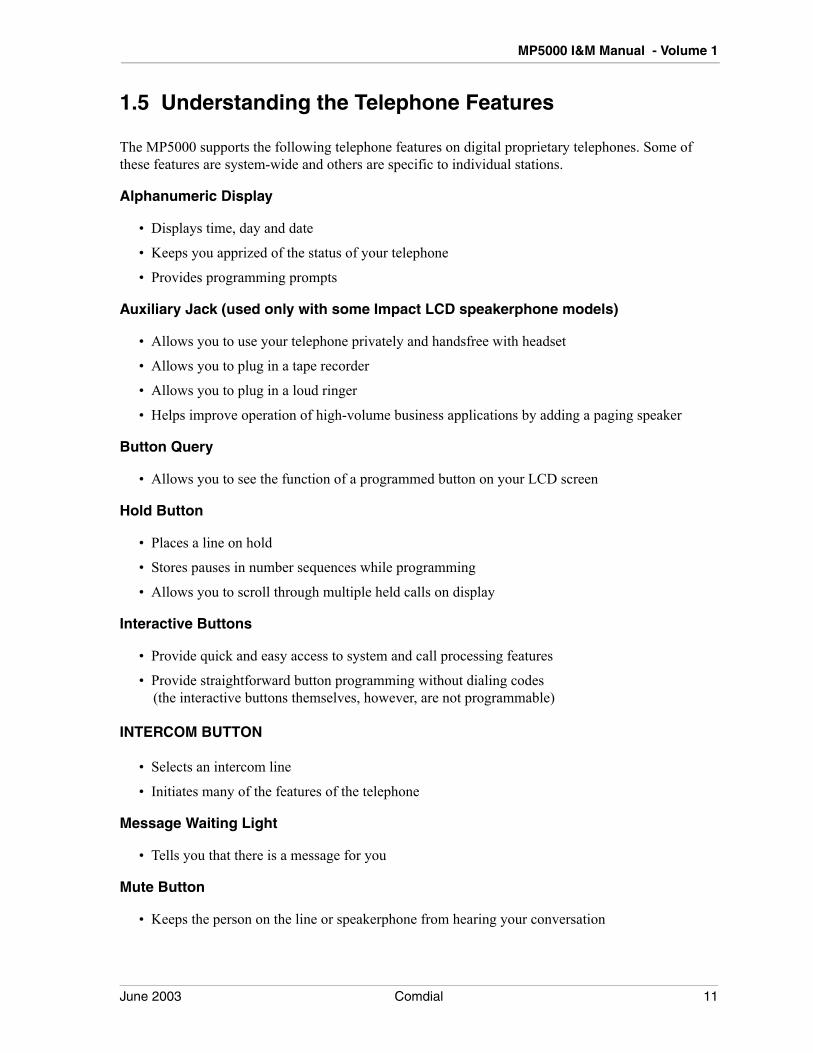
1.5 Understanding the Telephone Features
The MP5000 supports the following telephone features on digital proprietary telephones. Some of these features are system-wide and others are specific to individual stations.
Alphanumeric Display
• Displays time, day and date
• Keeps you apprized of the status of your telephone
• Provides programming prompts
Auxiliary Jack (used only with some Impact LCD speakerphone models)
• Allows you to use your telephone privately and handsfree with headset
• Allows you to plug in a tape recorder
• Allows you to plug in a loud ringer
• Helps improve operation of high-volume business applications by adding a paging speaker
Button Query
• Allows you to see the function of a programmed button on your LCD screen
Hold Button
• Places a line on hold
• Stores pauses in number sequences while programming
• Allows you to scroll through multiple held calls on display
Interactive Buttons
• Provide quick and easy access to system and call processing features
• Provide straightforward button programming without dialing codes (the interactive buttons themselves, however, are not programmable)
INTERCOM BUTTON
• Selects an intercom line
• Initiates many of the features of the telephone
Message Waiting Light
• Tells you that there is a message for you
Mute Button
• Keeps the person on the line or speakerphone from hearing your conversation
June 2003 Comdial 11
Introducing the CONVERSip MP5000 Multimedia Platform
Programmable Buttons
• Allow you to program your telephone for automatic dialing functions
• Allow you to program your telephone for Direct Station Selection (DSS)
• Show which lines and intercoms are either in use or on hold
• Allow you to store frequently used feature codes at unused buttons
Ringer Volume Control
• Lets you vary ringer volume
Shift Button
• Allows you to program and access pre-programmed feature codes or secondary speed dial numbers (each programmable button can accommodate two feature codes or speed dial numbers)
Speaker Button
• Turns your speaker on or off
• Disconnects a call when your handset is on-hook
• Ends or cancels programming
Status Lights
• Shows status of line when next to line button
• Shows status of station when next to DSS button
• Shows status of feature when next to programmable button
TAP Button
• Recalls dial tone, or activates host system features (must be programmed for either feature)
• Retrieves held calls (last call held is first call retrieved)
Transfer/Conference Button
• Transfers calls
• Sets up conference calls
Volume Control
• Regulates the volume of the speaker and the handset
12 Comdial June 2003
MP5000 I&M Manual - Volume 1
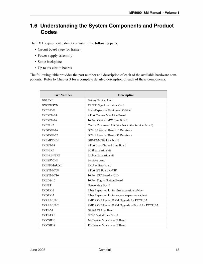
1.6 Understanding the System Components and Product Codes
The FX II equipment cabinet consists of the following parts:
• Circuit board cage (or frame)
• Power supply assembly
• Static backplane
• Up to six circuit boards
The following table provides the part number and description of each of the available hardware com-ponents. Refer to Chapter 3 for a complete detailed description of each of these components.
Part Number DescriptionBBLFXII Battery Backup Unit
DXOPT-SYN T1 /PRI Synchronization Card
FXCBX-II Main/Expansion Equipment Cabinet
FXCMW-08 8 Port Centrex MW Line Board
FXCMW-16 16 Port Centrex MW Line Board
FXCPU-2 Central Processor Unit (attaches to the Services board)
FXDTMF-16 DTMF Receiver Board-16 Receivers
FXDTMF-32 DTMF Receiver Board-32 Receivers
FXEMDD-DF DID/E&M Tie Line board
FXGST-08 8 Port Loop/Ground Line Board
FXII-EXP SCSI expansion kit
FXII-RBNEXP Ribbon Expansion kit.
FXIISRV2-II Services board
FXINT-MAUXII FX Auxiliary board
FXISTM-C08 8 Port IST Board w/CID
FXISTM-C16 16 Port IST Board w/CID
FXLDS-16 16 Port Digital Station Board
FXNET Networking Board
FXOPX-1 Fiber Expansion kit for first expansion cabinet
FXOPX-2 Fiber Expansion kit for second expansion cabinet
FXRAMUP-1 SMDA Call Record RAM Upgrade for FXCPU-2
FXRAMUP-2 SMDA Call Record RAM Upgrade w/Board for FXCPU-2
FXT1-24 Digital T1 Line Board
FXT1-PRI ISDN Digital Line Board
FXVOIP-L 24 Channel Voice over IP Board
FXVOIP-S 12 Channel Voice over IP Board
June 2003 Comdial 13
Introducing the CONVERSip MP5000 Multimedia Platform
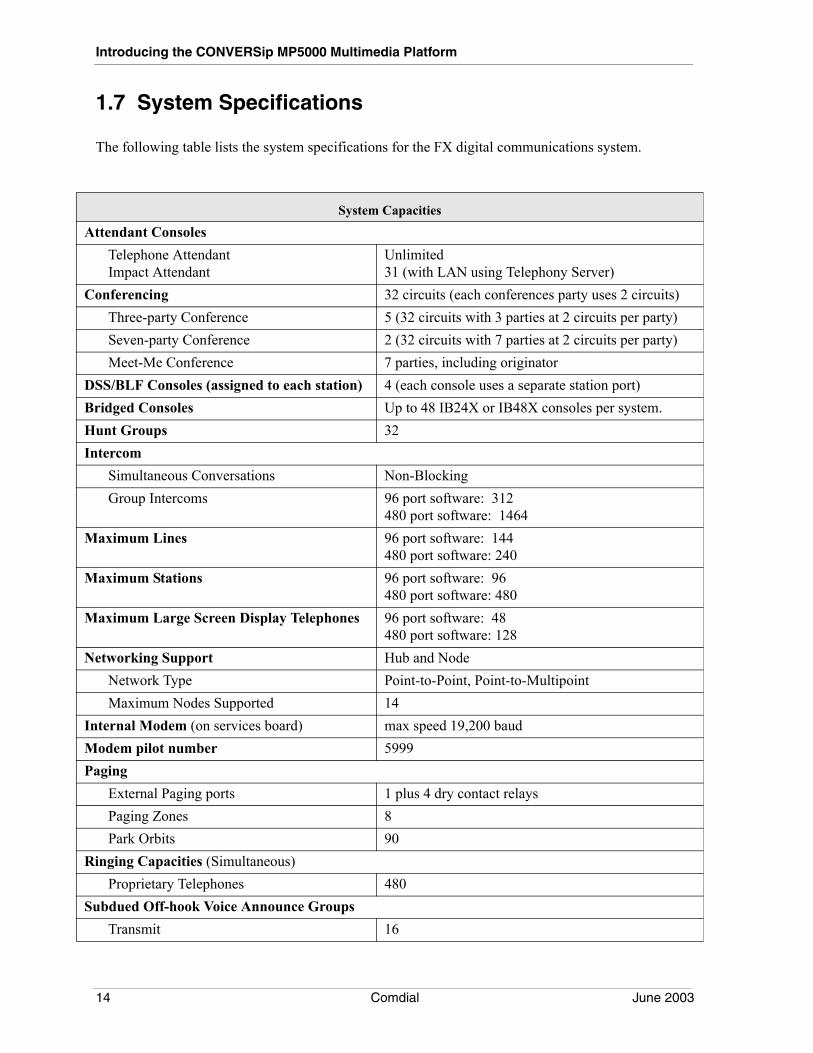
1.7 System Specifications
The following table lists the system specifications for the FX digital communications system.
System Capacities
Attendant ConsolesTelephone AttendantImpact Attendant
Unlimited31 (with LAN using Telephony Server)
Conferencing 32 circuits (each conferences party uses 2 circuits)Three-party Conference 5 (32 circuits with 3 parties at 2 circuits per party)Seven-party Conference 2 (32 circuits with 7 parties at 2 circuits per party)Meet-Me Conference 7 parties, including originator
DSS/BLF Consoles (assigned to each station) 4 (each console uses a separate station port)Bridged Consoles Up to 48 IB24X or IB48X consoles per system.Hunt Groups 32Intercom
Simultaneous Conversations Non-BlockingGroup Intercoms 96 port software: 312
480 port software: 1464Maximum Lines 96 port software: 144
480 port software: 240Maximum Stations 96 port software: 96
480 port software: 480Maximum Large Screen Display Telephones 96 port software: 48
480 port software: 128Networking Support Hub and Node
Network Type Point-to-Point, Point-to-MultipointMaximum Nodes Supported 14
Internal Modem (on services board) max speed 19,200 baudModem pilot number 5999Paging
External Paging ports 1 plus 4 dry contact relaysPaging Zones 8Park Orbits 90
Ringing Capacities (Simultaneous)Proprietary Telephones 480
Subdued Off-hook Voice Announce GroupsTransmit 16
14 Comdial June 2003
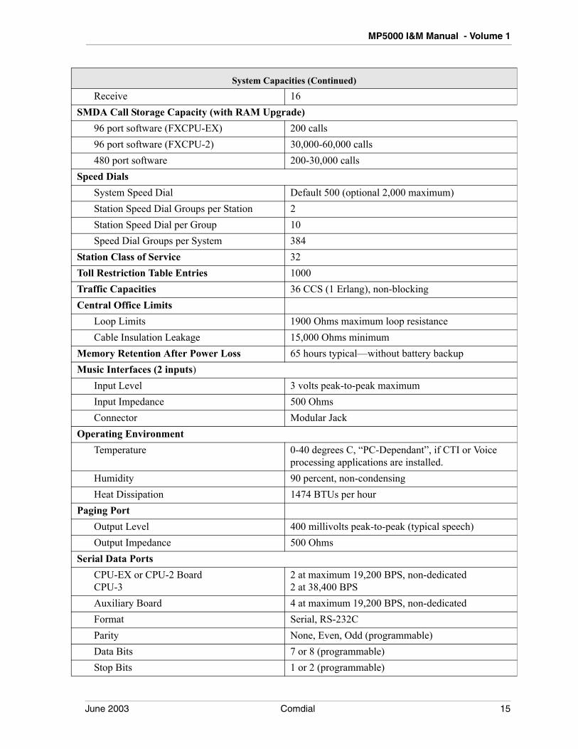
MP5000 I&M Manual - Volume 1
Receive 16SMDA Call Storage Capacity (with RAM Upgrade)
96 port software (FXCPU-EX) 200 calls96 port software (FXCPU-2) 30,000-60,000 calls480 port software 200-30,000 calls
Speed DialsSystem Speed Dial Default 500 (optional 2,000 maximum)Station Speed Dial Groups per Station 2Station Speed Dial per Group 10Speed Dial Groups per System 384
Station Class of Service 32Toll Restriction Table Entries 1000Traffic Capacities 36 CCS (1 Erlang), non-blockingCentral Office Limits
Loop Limits 1900 Ohms maximum loop resistanceCable Insulation Leakage 15,000 Ohms minimum
Memory Retention After Power Loss 65 hours typical—without battery backupMusic Interfaces (2 inputs)
Input Level 3 volts peak-to-peak maximumInput Impedance 500 OhmsConnector Modular Jack
Operating EnvironmentTemperature 0-40 degrees C, “PC-Dependant”, if CTI or Voice
processing applications are installed.Humidity 90 percent, non-condensingHeat Dissipation 1474 BTUs per hour
Paging PortOutput Level 400 millivolts peak-to-peak (typical speech)Output Impedance 500 Ohms
Serial Data PortsCPU-EX or CPU-2 BoardCPU-3
2 at maximum 19,200 BPS, non-dedicated2 at 38,400 BPS
Auxiliary Board 4 at maximum 19,200 BPS, non-dedicatedFormat Serial, RS-232CParity None, Even, Odd (programmable)Data Bits 7 or 8 (programmable)Stop Bits 1 or 2 (programmable)
System Capacities (Continued)
June 2003 Comdial 15
Introducing the CONVERSip MP5000 Multimedia Platform
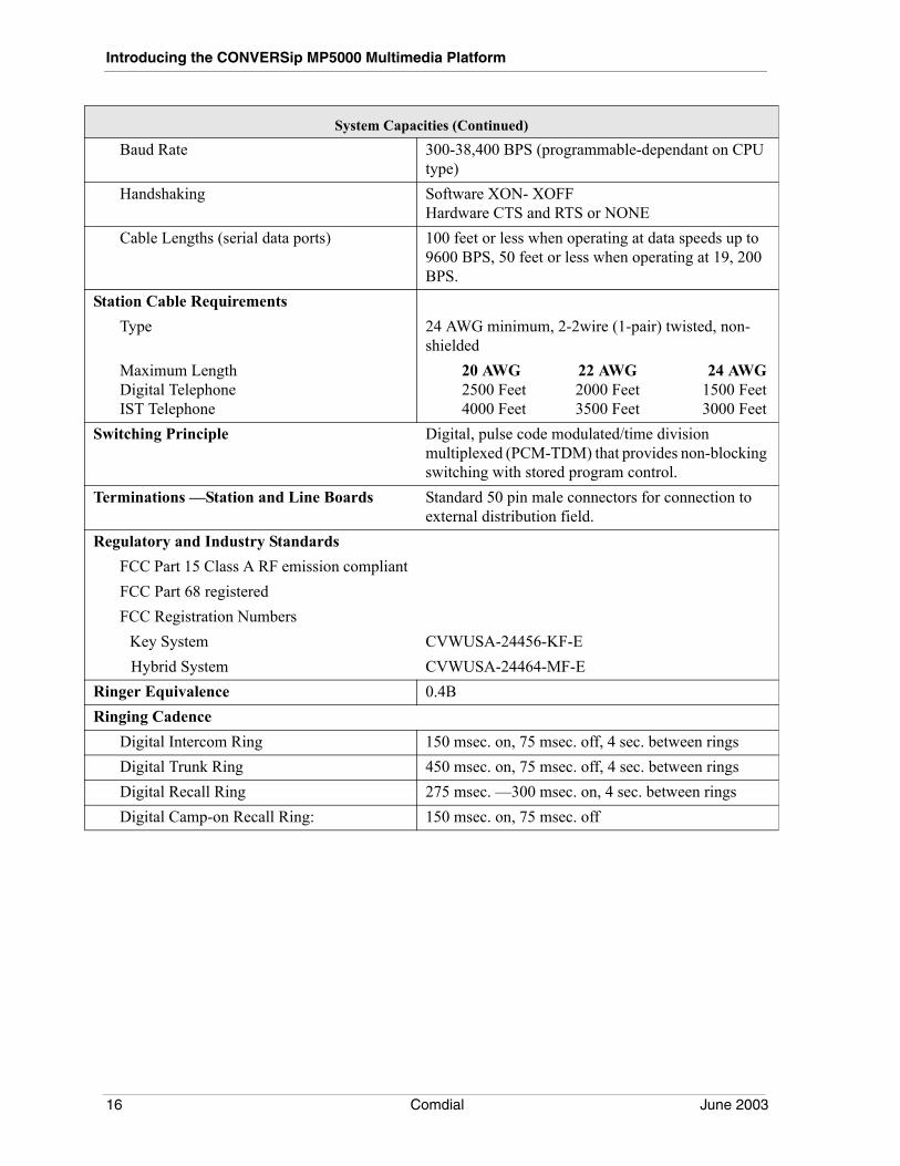
Baud Rate 300-38,400 BPS (programmable-dependant on CPU type)
Handshaking Software XON- XOFFHardware CTS and RTS or NONE
Cable Lengths (serial data ports) 100 feet or less when operating at data speeds up to 9600 BPS, 50 feet or less when operating at 19, 200 BPS.
Station Cable RequirementsType 24 AWG minimum, 2-2wire (1-pair) twisted, non-
shieldedMaximum LengthDigital TelephoneIST Telephone
20 AWG 22 AWG 24 AWG2500 Feet 2000 Feet 1500 Feet4000 Feet 3500 Feet 3000 Feet
Switching Principle Digital, pulse code modulated/time division multiplexed (PCM-TDM) that provides non-blocking switching with stored program control.
Terminations —Station and Line Boards Standard 50 pin male connectors for connection to external distribution field.
Regulatory and Industry StandardsFCC Part 15 Class A RF emission compliantFCC Part 68 registeredFCC Registration Numbers
Key System CVWUSA-24456-KF-E Hybrid System CVWUSA-24464-MF-E
Ringer Equivalence 0.4BRinging Cadence
Digital Intercom Ring 150 msec. on, 75 msec. off, 4 sec. between ringsDigital Trunk Ring 450 msec. on, 75 msec. off, 4 sec. between ringsDigital Recall Ring 275 msec. —300 msec. on, 4 sec. between ringsDigital Camp-on Recall Ring: 150 msec. on, 75 msec. off
System Capacities (Continued)
16 Comdial June 2003
MP5000 I&M Manual - Volume 1
2. UNDERSTANDING THE SYSTEM FEATURES
2.1 Feature Listing
This list describes all of the features available on the MP5000 System.
AAbandoned Hold Release
If a distant on-hold party hangs up, it may cause an interruption in the line current. In that situation, the switch will drop the line from the hold condition and returns it to service. You can program the time interval between hang-up and line-drop with choices of either 50 milliseconds or 350 milliseconds. The central office makes the arrangement for the time choice. Also refer to the discussion titled Dis-connect Supervision.
Access Denied
If you have programmed the system to do so, it can deny access to particular lines and group intercoms at certain telephones. A user cannot select a line for use if it is access denied at their telephone.
Account Code Button
As part of the button mapping, the system installer can assign a special button that the user may use to apply an account code to a call. Refer to the discussion titled Account Codes With Positive Verification.
Account Codes with Positive Verification
Station users can assign account codes to specific calls. The system uses the account codes to identify calls by category, or special grouping, for call accounting purposes. All calls with the same account code are reported together by the station message detail accounting (SMDA) feature.
The system attendant can obtain a separate printout of calls assigned to one account without causing any other calls to print or be deleted. The installer can arrange for the system to verify that the user entered an account code and to sound an error tone if an invalid account code is entered. He or she may program the system to prompt station users to enter account codes for incoming calls and/or out-going calls if desired. The prompt can be with or without system verification of the entry. Alternately, account code prompting can be turned off completely. Depending upon the type of call, different users are associated with the call accounting record. The following list explains to whom the call record is associated:
• on out-going calls, the user who enters the account code,
• on transferred calls, the transferee,
• on incoming calls, the last user active on a call.
Account codes may be from three to 16 digits in length as set by class of service programming. The system will verify all digits. Also refer to the discussion titled Account Codes With Positive Verifi-cation—Forced.
March, 2004 Comdial 13
Understanding the System Features
Account Codes with Positive Verification—Forced
Station users can assign account codes to specific calls. The system uses the account codes to identify calls by category, or special grouping, for call accounting purposes. If the installer programs the system to have forced account codes, the user must enter the account code before the call can be placed. If the system does not find a match between a user entered account code and one that the installer has set in the system, the call will not be allowed. Verification alone does not deny users’ calls, only forced verification denies.
The installer can program the system to verify that the user entered an account code and to sound an error tone if an invalid account code is entered. If programmed, attendants can use account codes as a basis for SMDA print-outs. You can program the system to recognize emergency numbers that do not require account codes.
Account Code Display and Display Time
For LCD speakerphone users, a message appears in the telephone’s display prompting the user to enter an account code for incoming or outgoing calls. If the user does not require this prompt, the installer should turn off the prompting message display.
All-Call Paging
Refer to the discussion titled Zone Paging.
Allow Ringer Off (Ringer Volume Off)
On some proprietary telephones, the user selects the ringer volume level by pressing a rocker-type volume control repeatedly to select one of four different volume levels. The lowest volume setting is essentially an off condition as the telephone sounds only one low-volume ring burst when a call rings the station. Sometimes users would rather not receive even one ring burst. For these cases, installers can program the system so that it completely silences the ringer at a telephone when its user selects the lowest volume setting.
Alpha-Numeric Calling Party and Line Display
An LCD speakerphone, when receiving an inside call, displays the caller’s name (up to seven char-acters). For example, “John L”. The system uses the remaining nine characters on the display for status messages (for example, “Fwd from”). The system also displays the logical line number of the current line. Also see the discussion titled Liquid Crystal Display Support.
Alternate Attendant
Refer to the discussion titled Attendant Position.
Answer Button
When you map a telephone with this button, the user can press it to answer the call that is audibly ringing at his or her station. It is possible for more than one call to be ringing at the same time; however, only one of those calls is answered with the answer button.
Also refer to the discussion titled Programmable Button Flexibility.
Area Paging Interface
Refer to the discussion titled External Paging Interface.
14 Comdial March, 2004
MP5000 I&M Manual - Volume 1
Attendant Position
The attendant of a telephone system is typically the first person to answer an incoming call and usually directs incoming calls to the proper person or department within the system. In addition to call control, the attendant controls system-wide operating features such as night transfer (of ringing) and the system clock. Additionally the attendant is responsible for programming such items as system speed dial numbers and LCD messages that are available to many of the system users.
Authentication/Authorization
This SIP feature provides security for SIP communications and prevents unauthorized logon as a SIP device. This authorization is password protected on a per station basis. Comdial’s SIP products utilize the ‘Digest’ method of authorization. This method encrypts the password to prevent the password from being seen with a network sniffer. SIP functionality requires Feature Set 18A and a CPU-III pro-cessor board.
Authorization Code
Authorization codes have a “walking class of service” option. Walking class of service provides system users the mobility to use their class of service (COS) features, prime line assignments, and exception numbers on any telephone in the system instead of being limited by what is available to the particular telephone they happen to be using. Authorization codes are associated with personal intercom numbers as is COS, prime markings, and exception numbers. Therefore, when a user enters his or her authorization code at any system telephone, the code alerts the system as to what features to make available to the user. The user can use the telephone for anything allowed by his or her personal intercom number; however, a user cannot disturb the last number redial stored there by the normal user. Once a user accesses his or her telephone features, those features remain in effect until any idle time exceeds the authorization code time-out period. A telephone user activates walking class of service by pressing Itcm and then dialing #08 followed by an authorization code. Also refer to the dis-cussion titled Lock Button.
Automatic Dialing
Refer to the discussion titled Station Speed Dial.
Automatic Hold—Intercom to Intercom/Line
If a user selects an intercom number while an existing intercom call is in progress, the first call will be automatically placed on hold. This feature allows a user to move from intercom call to intercom call without having to press the Hold button. The installer must enable this feature for it to be available.
Automatic Hold—Line to Intercom
If a telephone user selects an intercom number while a line call is active, this feature causes the system to automatically place the line call on hold. This is a fixed system feature and is always available.
Automatic Hold—Line to Line
If a user selects a second line during the time that they are already active on a line, this feature causes the system to automatically place the first line call on hold. The feature allows a user to move from line call to line call without pressing the Hold button. The installer must enable this feature for it to be available.
March, 2004 Comdial 15
Understanding the System Features
Automatic Number Identification (ANI)
Automatic Number Identification (ANI) is a T1 service feature for both E&M and DID lines. Long dis-tance common carriers offer ANI as a feature to dial 800 and dial 900 lines. The ANI feature provides information to an internal telephone system that identifies the telephone number of the calling party. When the ANI feature is combined with the Dialed Number Identification Service (DNIS) feature, the common carrier also delimits the DNIS information from the ANI information with an asterisk (*) tone so that the system can process each portion properly.
ANI/DNIS Enhancements
Installers can program an option to support the DTMF ANI/DNIS with two information digits. When enabled, the format of the digit string changes from the SANISDNISS format to a format that includes a two-digit code that indicates the presence of ANI digits (I ANI DNIS where I equals the two-digit string). The ANI digit string indicates the calling party’s telephone number. The DNIS digit string identifies the call destination station.
Also refer to the paragraph titled Dialed Number Identification Service (DNIS).
Automatic Pause Insertion
When the system stores a dialed number for later redial, it automatically stores a pause whenever the user waits between digits for at least two seconds while dialing the number. The system inserts the automatic pause in the stored number sequence at the point where the manual pause in dialing occurred. The actual time length of the inserted pause is programmable.
Automatic Privacy
The installer can make a line private or non-private. In the private mode, a station has exclusive use of the line during a call. No other station can access that line unless the original user includes it through the use of the add-on conference feature. In the non-private mode, any stations with that line appearance can gain access at the same time (sometimes known as common line pickup). Users may add up to five parties into one conversation. Also see the discussions titled Conferencing —Multiline and Privacy Release.
Automatic Redial (ARD)
With this feature, the system automatically redials a busy or unanswered outside call. Once the user activates automatic redial, the station selects the line, automatically dials the number, and waits for a response. If the called station does not answer, the redialing station disconnects, waits one minute, and then repeats the sequence. The station will make 2 attempts to redial the number. The feature cycle is timed and does not have busy and ring-no-answer detection circuitry. Because of this, if the redialing user is operating handsfree when the called party answers, he or she must take the handset off-hook to prevent being cut off by the timing cycle. The station users must program an Auto Redial button at one of the designated programmable button locations on their telephones before they can use it.
The enhanced automatic dialing feature adds a multiple redial feature. When installer enable this option, the station can have multiple numbers queued for ARD (automatic redial). You can enable this feature for as many as 80 stations at a time in Impact FXII.
16 Comdial March, 2004
MP5000 I&M Manual - Volume 1
When you enable multiple ARD, a station can store up to the last 10 numbers its user dials as the user dials the numbers. As the user dials the 11th number, the system drops the oldest number and adds that last dialed number at the top of the list of the 10 stored numbers. It repeats this sequence as the user makes more calls during the day. The system will compare a selected line along with a newly dialed number with its currently stored list. If it encounters a match, it does not store the number again; however, it does move the matched line/number to the top of the list.
After the station user starts a redial on some of the numbers in the stored list, only the places in the list occupied by numbers not currently being redialed remain available for new number addition.
When the user starts the ARD feature, the telephone will redial the stored number. With multiple ARD, the telephone will redial all stored numbers one at a time, in the order that they are stored in the queue, until (a) the call is answered, (b) the user cancels the automatic redial feature for a particular number, or (c) the telephone has dialed the number a pre-programmed number of times.
If the system encounters a busy or unavailable line (for lines that have provision for reporting such matters) or if the system encounters a ring-no-answer, and it has not dialed the number the pre pro-grammed amount of times, it moves the number to the bottom of the queue and tries the next queued number just as soon as the redial delay times out.
To completely program the automatic redial feature, the installer must enable the multiple automatic redial feature and adjust the following feature parameters:
Suspend ARD
With this Suspend ARD feature selected, user activity at a station suspends automatic redial action until the user completes the activity. When the user activity ends, the system automatically resumes the automatic redial action. Also, users can dial a code to manually suspend ARD action until they choose to restart it by either pressing the ARD button or by dialing the code once more. With the feature dis-abled, any user activity cancels further ARD action.
ARD Answer Supervision
With the ARD Answer Supervision feature selected, and the line that the system is using to make the call provides answer supervision capability, the system stops the ARD activity when the called party answers.
ARD Wait For Answer
The ARD Wait For Answer Feature sets the maximum time the system will wait for an answer signal or user activity before it cancels the ARD action after it redials the number. If neither call answer not user activity occurs, the system terminates the call and retries the call unless the maximum number of retries has been reached.
If the line provides busy detection, the system disconnects the call and provides a five second busy tone to the calling station. In this situation, the calling station remains in the redial mode until the busy tone stops. Any user activity during this period deactivates ARD for the number.
ARD Retry Delay
The ARD Retry Delay feature sets the time the system waits before redialing number or between redi-aling one number and the next when multiple ARDs are active. If ARD activity is suspended at the time the retry delay timer expires, the number to be redialed next remains at the top of the queue to be redialed first when ARD resumes.
March, 2004 Comdial 17
Understanding the System Features
ARD Retries
The ARD Retries feature sets the maximum times the system will automatically redial a queued number.
Automatic Reports
This feature makes the system automatically generate selected station message detail accounting and call costing reports for printing on a daily or weekly basis. The installer sets the time that the report is to be printed, sets the type of report to be printed, and dictates whether the call records are to be erased from the system memory after they have been printed.
Automatic Route Selection (ARS)
Automatic Route Selection (ARS) allows the system to automatically select the least costly line group available to a station to route a call. The system modifies the dialed number, if needed, to match the selected line group. Additionally, ARS provides the costing information for the dialed call that is reported by the station message detail accounting feature. ARS makes routing decisions (which lines to route a call over, if and how to modify a number, and costing information) based entirely upon the pro-gramming of the system.
ARS Access Per line Group
This feature allows the access code for any line group in the system to provide access to ARS. By default, the line group 1 access code will provide ARS access when ARS is enabled. You can program this item on a line group parameter.
ARS Delayed Dialtone
This feature adds a delay option for ARS Dialtone (Dial Tone 4). When the telephone user selects an outside line, there is a 1 second delay before dial tone is presented to the caller. The dial tone frequency is the same as the system intercom dial tone, but the delay gives the impression a “fresh” dial tone for outbound dialing.
ARS Hookflash Restriction
This feature enhances ARS response to hookflash action on an outside line when that action is fol-lowed by dialed digits. With the feature enabled, the system delays response to a hookswitch flash until after the ARS feature verifies as valid all subsequent dialed digits. With the feature disabled, the system sends the hookflash over the line without waiting for the ARS feature to verify the validity of subsequent dialed digits. This station class of service feature is applicable only when the ARS feature is active.
Automatic Station Relocation
The system will automatically recognize a particular station should someone relocate it to a different station port. After being installed at a new port location, a relocated station will provide the same class of service parameters and station features that it provided at its original port location. Also, the relo-cated station will respond to the same personal intercom number that it responded to at its original port
18 Comdial March, 2004
MP5000 I&M Manual - Volume 1
location. A relocated station prompts the user to take action to either accept its original programming or accept the programming at the new port. If the user takes no action, the station assumes the param-eters and personal intercom number that is determined by a system programming procedure. Consider these following points when you enable station relocation:
• if someone does a station relocation, the installer must save the database programming to make the relocation permanent,
• this relocation feature only applies to digital telephones,
• users must ensure that the vacated port remains unused until they complete a relocation,
• if someone connects a telephone to the vacated port before users complete a relocation, the relocated telephone will not retain its original programming,
• when the user accept the original programming for the new port, the vacated port assumes the programming currently assigned to the new port (that is, a parameter exchange takes place between the vacated port and the new port),
• if a DSS/BLF console was assigned to the telephone at its original location, the console assignment follows the telephone to the new location even though the console is no longer located physically near the telephone. If the user relocates the console, the system installer must reprogram the new port for console use.
The relocation feature also applies to relocated digital telephone boards, however, the installer must ensure that the vacated port remains unused until the relocation is complete. All stations connected to the relocated circuit board show the relocation prompt.
Auxiliary Equipment Interface (Busy Lead Detection)
One line port on every loop start line board will detect current flow on the line ahead of the common equipment. When an external device, such as a modem or fax, is connected to this line and is activated, current flow over the line occurs. When the port detects the current flow, the system causes a busy indication for this line to appear at every system telephone that has its appearance. Normally, the user cannot interrupt an external device by pressing the line button or by dialing a line group code; however, if the line is programmed to be non-private, a user can interrupt the device.
March, 2004 Comdial 19
Understanding the System Features
Auxiliary Station Ringer Interface
The central processor unit circuit board includes four dry-contact relay actuations. They may be used for the following:
• Programmable Station Ringer Interface
• Paging Enable
• Door Relay Lock/Unlock
• Zone Night Answer
The relay contacts for the station ringer interface follows the ring pattern of a ringing line or telephone. Contacts on relay 1 is normally closed when idle and contacts on relays 2, 3, and 4 are normally open when idle.
Also refer to the discussions titled Common Audible Ringer Interface, External Paging Interface, Flexible Ringing Assignments, Line Answer From Any Station, and Night Transfer (Of Ringing).
BBackground Music (Two Selections)
If the system includes an external music source, telephone users can turn background music on and off at their stations. The system uses two dedicated audio ports to interface the music sources, one for background music through the station speakers and the other for music on hold for both lines and intercom numbers. Station users can dial a code to choose either source for their background music.
Also refer to the discussions titled Music Interface and Music On Hold.
Battery Backup (Chassis, Cable, and Batteries)
Battery back-up assemblies that include chassis, cable, and battery are available as optional kits (through normal distribution from Comdial). The battery back-up assembly connects directly to the battery interface connector on the system main power supply.
Battery Backup Interface
Attach a Comdial-provided optional battery backup kit to the FX for full un-interruptible system power in case of an AC power loss. (When installers connects a battery back-up assembly to the system, they must first connect AC voltage to the power supply and set the AC power switch to On.) The switching and trickle charge circuitry are in the common equipment power supply assembly, but batteries, chassis, and cable are packaged as a separate option. When the installer plugs the system into an active AC power source, the common equipment power supply will constantly charge the attached batteries with a trickle current. Built-in circuitry automatically switches to battery power when AC power is lost. With batteries at full charge, a fully loaded system (without expansion cabinets) will remain fully functional for a minimum of one hour without AC power.
Block Programming
A installer can assign the programmed features of a particular line or station, to other lines or stations. This feature eliminates the need to individually program every station class of service, line and/or button function.
20 Comdial March, 2004
MP5000 I&M Manual - Volume 1
Busy Button Inquiry
This feature provides the user with a means to identify both a station that is busy on a line and the line the station is busy on as well. The system presents the identified line or station information on the user’s telephone display for 10 seconds after he or she requests that information. If the system installer has not given the user’s telephone this feature, the system presents busy information to the display without identifying the line or station involved.
Button Mapping
Refer to the discussions titled, Full Button Programmability Of Features, Programmable Button Flex-ibility, and Square/Non Square Configuration.
Button Query
The button query feature allows users to display the function of programmable buttons on LCD tele-phones.
CCall Announce with Handsfree Answer-back
The internal speaker at each full–featured multiline telephone provides call-announce capability over the personal intercom number. Users can call announce between all telephone types except between an analog monitor telephone and digital telephones. When a user makes a call-announce intercom call to the personal intercom number of another telephone, the user of that telephone can make a handsfree response to the call. If the personal intercom number is forwarded or is in a hunt group, the intercom call will appear as a tone signaled intercom call at the telephone to which the calls are forwarded. A tone burst, programmable by the installer, precedes the call announce.
Call Announce Beeps (Call Announce Tone Bursts)
Installers can set the number of call announce tone bursts for each station in the system to be a value of from one to five.
Call Costing and Station Message Detail Accounting Reports
The system provides built-in, estimated costing of all calls. It also provides station message detail accounting (SMDA) reports of all calls, and it displays call costs on LCD speakerphones. Call costing, in general, provides a means of establishing costs to be applied to outside calls made from system tele-phones. Call costing computes charges for a call after it is completed but does not restrict dialing as toll restriction does. Call costs are based on a two-tier time rate and include a line surcharge cost. The installer can make allowances for call set-up and minimum call duration using the answer time and dial time parameters. The system determines call costing through the use of the toll restriction and auto-matic route selection (ARS) features; however, these features need not be active for costing to work. Call costing is based on programmed estimates that best fit the particular area of the country the system is installed in.
March, 2004 Comdial 21
Understanding the System Features
Caller ID
FXII caller ID provides relevant caller information (caller’s name and number, for example) to any called LCD stations. The installer can program any C.O. line as a caller ID line. The caller ID infor-mation is also reflected in the SMDA printout. The FXII Caller ID feature package requires the use of a CID08 unit—hardware designed to support the Bell 202 Caller ID signal transmitted by the central office. The CID08 supports up to 8 CO lines (you can install up to 8 CID08 units), for a total of 64 caller ID lines.
Caller ID on Voice Mail
The feature provides for Caller ID information to be sent to the Comdial voicemail along with the callers message. The voicemail system attaches the Caller ID information to the message, allowing the user the option to return the call from their voicemail box.
Caller ID RNA—Ring–No–Answer
If a station with assigned caller ID lines receives a call but does not answer, the system will automati-cally archive the caller ID information. The installer can program any station or group of stations to receive Caller ID RNA information. Upon reviewing a Caller ID RNA record, the user can automati-cally redial that number by pressing the SAVE button. When the caller ID information goes to more than one telephone, the system will also display the last station user that viewed that record, thus pre-venting multiple call backs. Caller ID RNA is a programmable feature.
Call Forward to Hunt Group
Incoming or transferred calls to a ring, no-answer (RNA) station that is set to forward calls to a hunt group can route to the hunt group’s voice mail box instead of to the station’s voice mail box. To achieve this result, enable Use Pilot Numbers as Voice Mail ID in the Station/Program-ming/Station Hunting/Options dialog. This action is limited to eight forwarded calls. After eight calls, the station’s voice mail box activates.
Call Forward—All Or Personal
Station users can forward the calls that normally ring at their telephones to another telephone for answering. They can forward just their prime line and intercom calls or forward every call that rings at their station. If users forward calls while the attendant has enabled the night transfer of ringing mode, the night mode ringing assignments at their stations are forwarded. There are multiple levels of for-warding. Station A can forward to station B, then station B can forward to station C, thus making calls to station A forward all the way to station C. For each internal call received while call forward is enabled, the forwarding telephone sounds a ring reminder (short tone burst) to remind the users that their calls are being forwarded.
If a telephone has an LCD display, it will show a call forward message along with the extension number or name of the station receiving the forwarded calls.
Also see the discussions titled Call Forward—Busy Or Ring No-Answer, Call Forward—Manual, and Default Busy Ring No-Answer Call Forward.
Note: When the system is equipped with the FXCMW-xx line board, external Caller ID devices are not required. The FXCMW-08 and FXCMW-16 line boards provide eight and sixteen lines respectively, with support for caller ID and message waiting services provided by the central office. System software release 193 or later should be used with these boards.
22 Comdial March, 2004
MP5000 I&M Manual - Volume 1
Call Forward—Busy or Ring No-Answer, All or Personal
Users can control whether the calls forward immediately on encountering a busy or after a pre pro-grammed number of rings.
Also see the discussions titled Call Forward - All Or Personal, and Default Busy Ring No-Answer Call Forward.
Call Forward—Immediate
The installer can map a call forward button on the user’s telephone that will allow the user to forward calls even if they are not busy. After a user determines where to forward a call and activates the call forward button, the system will immediately forward the call once the line rings.
Call Forward Outside System (CFOS)
The Call Forward Outside System (CFOS) feature allows the system to forward incoming or trans-ferred line calls or intercom calls to telephone numbers that are outside the system. The CFOS feature forwards calls over any available outbound lines or line groups. Since CFOS involves outbound calls, those calls are subject to all line access, toll restriction, and automatic route selection restrictions nor-mally imposed on the users. Any calls that CFOS can not service (no outbound line available, toll restricted, and so forth), ring the system as normal calls. Note also that CFOS will not forward calls associated with group intercoms and hunt groups. With this Ring No Answer (RNA) capability, the system rings a station a programmed number of rings and then forwards the call outside the system based upon the programmed CFOS setting. To assist system managers keep account of CFOS activity, the system marks CFOS calls with an F in the SMDA records printout.
For CFOS to function properly, the associated incoming and outgoing lines must provide disconnect supervision. Calls forwarded through CFOS may experience lower audio levels due to the normal line resistance of CO lines. If signal loss is a problem at a particular site, the installer may need to add a line amplifier (repeater) in the lines.
The Call Forward Outside System (CFOS) feature also includes forwarding outside of the system for direct and transferred personal intercom calls. Any restrictions that the CFOS feature currently imposes on forwarded calls applies to forwarded personal intercom calls as well.
Call Forward, Recall
If the site includes ExecuMail equipment and the installer has arranged for the ExecuMail to provide release transfer, she or he should also arrange for the ExecuMail station to have this call forward, recall feature. Also see the discussion titled Call Forward—Busy or Ring No-Answer, All Or Personal.
Call History
This feature permits Softphone users to display a list of Missed Calls, Dialed Calls, and Answered Calls. This feature requires Feature Set 18A or greater, a CPU-III central processor, and Softphone.
March, 2004 Comdial 23
Understanding the System Features
Call Park
The system can hold 90 calls in park zones (also referred to as orbits) where they are retrievable by all users in the system.
Those calls that users can park include intercom calls, outside calls, and conference calls. Users park calls in predefined zones and then retrieve them by dialing an intercom feature code or by pressing a pre programmed call park button. When users retrieves a call from park orbit, the system places the call on the users selected intercom. The park orbit dialing codes are *910 through *999 and the retrieve codes are #910 through #999.
Also see the discussion titled Call Park Recall.
Call Park Recall
If a call remains unanswered after the park recall time has ended, the system returns the call to the parking station where it rings. If that telephone includes an LCD display, a message appears on it that shows the park orbit number of the returning call as well as the line number. The system installer sets the call park recall times. The retrieve codes are #910 through #999.
Also refer to the paragraph titled Call Park.
Call Pick-Up Directed
A station user can dial a code and the intercom number of a ringing station to answer the call.
Call Pick-Up Group
If a call rings to any station in a pre programmed pick-up group, and a second user in the group wishes to answer the call, the second user can dial the group pick up code to answer the call. Up to 16 different groups can exist with any number of stations in a group. The system provides group overlap by allowing stations to be in more than one group at the same time thus enabling them to pick up calls for stations in each group. The installer places the stations in their logical answering groups.
Call Pick-Up System
If a call rings at any station in the system, certain other station users, such as the attendant station, can pick up that call. That station user must dial the appropriate pick up code to answer the call, and the station must be programmed to pick up the call. The installer places all telephones in the same pick-up group to enable this feature.
Call Transfer—Screened
Screened call transfer allows users to first announce and then transfer both line and intercom calls from one station to another station or group in one of two ways. If both stations have access to the line or intercom number, the user makes a common line pickup transfer. If the other station does not have access to the incoming line, the user makes a transfer using the system transfer feature. The user uses the Trans/Conf button to effect the call transfer. Also refer to the discussions titled Call Transfer—Unscreened with Automatic Camp-On, and Hot Transfer.
24 Comdial March, 2004
MP5000 I&M Manual - Volume 1
Call Transfer—Unscreened with Automatic Camp-On
Unscreened call transfer allows users to transfer both line and intercom calls from one station to another station or group without first announcing them. The unscreened transferred call appears at the other station where it will ring if that station is idle or automatically camp-on and await an answer if that station is busy. The call automatically rings back to the transferring station after a programmed recall period. There is no limit as to how many calls that can be camped onto another station. A trans-ferred call will ring if the called intercom number is idle. If the handset is off-hook, the ringing is subdued.
Call Waiting Tone
A user can send a call waiting tone to signal to a busy station that he or she wishes that station to contact them. They do this by dialing a special code when they encounter a busy signal. The call waiting tone sounds at the busy station and reoccurs until the calling party hangs up. The frequency of the call waiting tone is programmed by the installer.
Camp-On with Automatic Call Back
After calling another station and encountering a busy signal or a ring with no answer, a user can camp on to that station, hang up, and wait to be called back by the system when that station becomes idle or when the user returns. Likewise, a user can camp-on to a busy line, hang up, and wait to be called back when it becomes idle.
When the busy station becomes idle, the system rings the originating station and starts a timer. The user of the originating station then goes off-hook and the camped-on telephone will ring.
Camp-On—Call Waiting
If a user makes a call to a busy telephone, he or she can send a call waiting tone to the busy telephone and wait on line for an answer. As soon as the called telephone returns to idle, it will ring with the camped on call.
Also refer to the discussion titled Call Waiting Tone.
Camp-On—No Answer
Refer to the discussion titled Camp–On With Automatic Call Back.
Central Message Desk
The installer can designate one station as the central message desk and arrange for it to have exclusive message waiting control. A central message desk user takes messages for other system users, controls the message waiting light at their telephones, and delivers the messages upon request.
Also refer to the discussion titled Message Waiting.
March, 2004 Comdial 25
Understanding the System Features
Central Processor Switched Data Port Configuration
The CPU board provides a dual in-line pin (DIP) switch that enhances installer convenience in setting up data communications between the telephone system and an external data device. The DIP switches provide a method of setting the data configuration to a known set of parameters without the need for reprogramming the system. With the DIP switch 1 set to On, the system provides the following data parameters:
Centrex Message Waiting with Caller ID
With this feature, a signal from an external message center lights a message waiting light on the system telephones and causes a message waiting display to appear on proprietary LCD speakerphones. Acti-vation of this feature requires the addition of Centrex Message Waiting line boards (p/n FXCMW-08 or FXCMW-16).
Channel Negotiation
Channel negotiation enhances the Primary Rate Interface (PRI) feature by preventing call collisions on both inbound and outbound calls. If a call originates from within the communications system and the selected channel is busy, the service provider needs to be able to deny the call or offer an available channel. The Channel Negotiation feature prevents call collisions by allowing the service provider to offer another channel to outbound calls if one is available. Conversely, if the service provider is attempting to send a call to a busy channel on the communications side, the system will not allow the call on that busy channel but offer an available channel as an alternate. The service provider can either accept this alternate or discontinue the call and attempt to reestablish it on a channel of its choosing.
There are no programming actions that installers need to take to enable this feature.
Clear Major Alarm Ring
Major alarm rings occur whenever a number of faults exceed a programmed threshold. You can use a telephone station to clear a major alarm ring by pressing the Intercom button and then dialing a feature code (default code is #09). However, the telephone station must have a class of service (COS) assigned to it that has this feature enabled. The installer enables this feature through COS programming.
Parameter COM 1 COM 2Baud Rate In 2400 9600Baud Rate Out 2400 9600Data Bits 8 8Stop Bits 1 1Parity Bits None NoneFlow Control None None
26 Comdial March, 2004
MP5000 I&M Manual - Volume 1
Common Audible Ringer Interface
Relay connections that provide dry-contact closure whenever ringing occurs are available on the central processor unit circuit board. The relay closure tracks the ringing pattern of the applied ring signal and is typically used to control an external ringer device. The installer can program the par-ticular ringing assignment that is tracked, and the ringing assignment can be any one of those that are provided by the flexible ringing assignment feature.
Also refer to the discussions titled Auxiliary Ringer Interface, External Paging Interface, Flexible Ringing Assignments, Line Answer From Any Station, and Night Transfer (Of Ringing).
Communications Card Support
The communications card provides serial data ports for interfacing such items as open architecture interface applications, PC attendant positions, and the SMDA data printer. Technicians install commu-nications cards on the auxiliary board. The auxiliary board will accept two communications cards in its front two slots. The FXII supports a maximum of 10 serial data ports. Two of these ports are the ports provided by the CPU board while communications cards provide the remaining eight ports. For related information, refer to the feature description titled Serial Data Port.
Conference Room
The conference room feature is developed for feature set 18A in order to support system based confer-ences inititated from a SIP device. Users can enter a conference room to speak with more than one other person at the same time. A user can be transferred into a room (ad-hoc conference), or dial directly into a room (meet-me conference). The rooms can be private (only users transferred into a room by the owner of the room), or public (any user can enter). Although this feature specifically sup-ports SIP compliant devices, it can also be used by legacy (digital or IST) stations.
Conferencing—Meet-Me
Meet-Me Conference is an arrangement where users (internal or external) dial into voicemail and enter a public conference room mailbox number; the voicemail system then transfers the caller into the public conference room. This feature requires feature set 18A or higher, a CPU-III processor board, and a Comdial voice mail system. The voicemail administrator must create a mailbox for each con-ference room.
Once members are in the conference, any internal station in the conference can dial ### to lock the conference, thus preventing any other parties from joining. Subsequent entries of the ### code will toggle the locking condition. Locking is not permitted when only one member is in the conference. When the room is locked, attendees will hear a long beep, followed by a short beep. When the room is unlocked, attendees will hear a short beep, followed by a long beep. For added security, members associated with an external trunk are not permitted to lock the door.
Attendees can leave the room without ending the conversation of other attendees in the room. The remaining users will hear a single beep when someone exits. When new parties enter a conference room, the exising members will hear a double beep, signifying that another party has entered the room.
The default numbers assigned in the switch to initiate a transfer into a public conference are 5801, 5802, 5803, 5804, and 5805. These numbers can be changed if desired by using the VMMI Pro-gramming/System/Feature Numbers menu.
March, 2004 Comdial 27
Understanding the System Features
Conferencing—Multiline
This feature allows one station to access other stations or lines at the same time resulting in a con-ference arrangement. Users press the transfer/conference button to establish conferencing.
A station user can make conference calls that encompass up to seven parties, including the originating station, in any combination of lines and system stations. After establishing a conference between his or her station and two external parties, the user can drop out of the conference by dialing a special code. The conference between the two outside parties continues in an unsupervised condition. During unsupervised conferences, a line-to-line connection exists through the system.
The installer can use the line-to-line connect duration feature to set the length of time that the system allows an unsupervised conference to continue.
Conference Advisory Tone
The conference advisory tone feature allows installers to configure the system to provide an audible tone whenever more than two parties are connected in a conference call. They may select this tone as either a one time tone or as a periodic recurring tone. If they choose a recurring tone, they must select the time interval between the recurring tones.
Console Support
The FXII supports the operation of a DSS/BLF console. The system installer must use a station port to install each DSS/BLF console; however, the installer can assign up to four DSS/BLF consoles to support the operation of one system station. When assigned to a station, a DSS/BLF console provides additional programmable buttons that the user can program as direct station select (DSS) buttons with associated busy lamp field (BLF) lights and as speed dial buttons (the console, however, does not support second-level speed dialing). The installer can also assign both outside lines and intercom numbers to console buttons when necessary. The station with which the console is assigned to work does not have to be a paired station port.
Console-less Operation
The system can operate with or without the use of an attendant console.
Consultation Hold
When the station user presses the transfer/conference button while on a call, the call is placed on con-sultation hold and dial tone is returned to the station. The user may then make another intercom or line call. After speaking with this “consulted” party, the station user may do any of the following: (1) return to the held call by selecting the line or intercom number for the held party, (2) effect a conference by pressing the transfer/conference button (putting the held call, the consulted party and the station user in conference), (3) hang up and effect a transfer of the held party to the consulted party. If the user encounters a busy or a ring no-answer, he or she may press the TAP button to return to the held party.
Copy Model
Refer to the discussion titled Block Programming.
28 Comdial March, 2004
MP5000 I&M Manual - Volume 1
COS Time of Day Routing
The system can have two classes of service (COS) for each station—one for the day 1 and day 2 mode and the other for the night mode of operation. With this feature, installers can select two different levels of COS for every station in the system if they desire. Of course, the system must be set for day 1, day 2, or night mode of operation for this two-tiered COS to be active; otherwise, the default day COS is in effect.
With this feature enabled at the stations, whenever the system automatically switches to the night transfer of ringing mode of operation, the night mode COS is automatically in effect. Also, when the attendant presses the Night Transfer Of Ringing button on his or her telephone, the night mode COS is in effect. When the attendant manually changes the system in this manner, the night mode COS remains in effect until the attendant returns the system to the day mode of operation.
COS time of day programming is available on the Stations/Station Programming/General screen where installers can enter a COS choice for day and night COS. Whenever the installer master clears the system, the night mode COS defaults to be the same as the day mode COS.
DDatabase Program Storage
Installers can save and restore the database using the visual man machine interface (VMMI).
Database Programming (from Main Station)
The system administrator can use a system telephone to reprogram certain feature parameters away from the values set by the installer using the computer-based VMMI. Included among the features that the system administrator can program are the ability to assign prime line, prime group, or prime intercom to the stations, and the ability to assign day and night toll restriction exception numbers to the stations.
Database Programming
System installers employing the visual man machine interface (VMMI) program running on a windows-based personal computer can customize the system parameters and change the system data base. The VMMI program causes the system to down load the existing database to the PC’s memory where the installer can make additions and changes to database. While the installer is reprogramming the database, the system allows users to continue to use their telephones but prevents them from making changes that affect the database’s structure. As the installer makes the changes to the database, the VMMI program sends these changes back to the system memory.
Data Interface Unit Support
The Data Interface Unit (DIU) provides the capability for using Industry Standard Telephone (IST) devices on a digital station port. These devices include such items as an Industry Standard Telephone, a FAX machine, modem, a cordless telephone, or an answering machine.
The DIU is a self-contained unit that includes the DIU cabinet, a wall transformer power supply with attached power cable, and a telephone line cord for system connection.
Day One and Day Two Ringing
Refer to the discussion titled Flexible Ringing Assignments.
March, 2004 Comdial 29
Understanding the System Features
Day Restriction Level
Refer to the discussion titled Toll Restrictions.
Daylight Savings Time
With this feature, the system automatically changes its clock to daylight savings time in the Spring and back to standard time in the Fall, at the nationally recognized date and time for Spring and Fall time changes. The default setting for Daylight Savings Time is off.
Default Busy/Ring No-Answer Call Forward
The installer can arrange for the system to automatically forward any calls that ring at busy telephones or any calls that ring and are not answered after a programmed number of rings. The installer chooses the station to receive those calls forwarded with this feature on a station-by-station basis; he or she can also program the number of rings (0-6) the system requires until it rolls the call to the forwarding station. The system defaults to four rings, three rings for voice mail ports. Users do not select this oper-ating feature since it is fully automatic; however, user-enabled call forwarding overrides this default busy ring no-answer call forwarding.
Also see the discussions titled Call Forward—All Or Personal; and Call Forward-Busy Ring No-Answer, All Or Personal.
Default Functional Programming
At initial power up of the system, the system operating features consist of a specific group of condi-tions (default conditions). These default conditions provide a completely operational system for normal use. A system installer can leave the system in a defaulted state or reprogram it as desired. After reprogramming, a installer can restore default conditions to the system at any time they are needed as follows
Delayed Ringing
Ringing assignments are programmable. An installer can program a station to provide delayed ringing on some lines while providing direct ringing on other lines.
Delayed Hot Line Operation
Current operating procedures allow installers to assign prime intercom to one station using another station’s intercom number to provide a hot line feature. With the hot line feature, the user of the station receiving the prime intercom assignment can take that station off-hook and be automatically connected to the station to which the intercom number is assigned. Additionally, installers can take programming action to delay this hot line action from taking place for a system defined period of time. With this pro-gramming choice in effect, the user of the station receiving the prime intercom assignment receives intercom dial tone for a short time before the hot line connection automatically takes place. This delay allows the station user to place intercom calls as well as effect hot line calls.
Diagnostics (Limited)
The installer can use this feature to perform maintenance routines and diagnose certain system mal-functions.
30 Comdial March, 2004
MP5000 I&M Manual - Volume 1
Dial 0 For System Attendant
A user can signal the system attendant station (station 1001 at default or any other station set by pro-gramming) by dialing the digit 0 on their personal or group intercom number.
Dial By Name
The Dial By Name feature allows users to employ any two-line display, LCD speakerphone and its interactive buttons to search through an index of names, locate a desired station name or system speed dial name, and automatically call the located item.
The dial by name feature uses the seven-character station names associated with the station ports for searching through the list of stations for intercom calling. The feature uses the 16-character identifying names for searching through the list of system speed dial entries for system speed dialing.
When users make a sequential search through the stored index of names, the system searches the list as it was entered. If system use requires a uniquely sorted list, installers or system attendants must arrange the list in the desired sequence as they store the entries.
Dial Pulse Inter-digit Time
You can set the inter-digit time between dial pulses when the system pulse–dials a number over a line. The FXII defaults this time to 200 milliseconds and provides a range of timing values in 100 milli-second intervals between 100 milliseconds and one second.
Dial Pulse Rate—Make/Break Ratio
You can set the line make / break ratio for rotary dial signaling in a more flexible manner. You can program the make and break times independently in one millisecond increments to any time from one to 99 milliseconds.
Dialed Number Identification Service (DNIS)
The DNIS feature allows the system to read an inband DTMF digit string sent by a common carrier. It uses this information to identify the telephone number the caller dialed and appropriately route the call. DNIS is a service that long distance carriers make available for dial 800 and dial 900 number sub-scribers on lines that use E&M signaling over a T1 network. Also see the discussion titled Automatic Number Identification (ANI).
Installers can program an option to support the DTMF ANI / DNIS with two information digits. When they enable this feature option, the format of the digit string changes from the SANISD-NISS format to a format that includes a two-digit code that indicates the presence of ANI digits (I ANI DNIS where I equals the two-digit string). The ANI digit string indicates the calling party’s telephone number. The DNIS digit string identifies the call destination station.
Also refer to the paragraphs titled Automatic Number Identification (ANI) and Automatic Pause Insertion.
March, 2004 Comdial 31
Understanding the System Features
Digit Q and Z Position
At default the system arranges for users to dial the 1 digit to represent both letters Q and Z; however, you can take programming action to move the Q and Z letters to the 7 and 9 digits respectively. After programming, the 7 digit represents the letters PQRS and the 9 digit represents the letters WXYZ. This programming action places the letters Q and Z in alphabetical sequence with the other letters in the alphabet. Some users find this reprogrammed arrangement easier to use than the defaulted arrangement.
Digital Line Remote Reset
This feature allows for technicians to perform a remote line reset for T1 or PRI lines.
Digital Wireless Telephone Support
The system supports the operation of the Scout, Scout II, and Scout III digital wireless telephone. The Scout series is a full-featured proprietary multiline telephone consisting of a wireless handset that lets the user roam about and still make and receive telephone calls.
Direct-In Lines (DIL)
The direct-in lines (DIL) feature provides a line appearance at a dedicated button on one or more mul-tiline telephones. The installer can assign a DIL to a proprietary single-line telephone where it provides one-way (either incoming or outgoing) or two-way operation depending upon further programming action.
32 Comdial March, 2004
MP5000 I&M Manual - Volume 1
Direct Inward Dialing (DID)DID Hunting
When a DID call rings at a station that the installer has disabled though programming action, the system routes the call through the disabled station’s hunt list until it locates a group inter-com for the call to ring. Should all group intercoms be busy or should no one answer the call in a programmed number of rings, the system then routes the call along the station’s call forward-ing arrangement. With a hunt list containing up to eight assigned group intercoms and access to each group intercom available to several system stations, many users have an opportunity to service a DID caller. Coupling this flexibility with the station’s call forwarding ability, provides many chances for system users to service DID calls. A installer could program a hunt list and a call forwarding scheme to an unassigned station and provide a designated DID termination and routing center. There would be no need to connect a telephone to the station port to use the fea-ture in this manner. The installer could arrange several DID termination centers to service dif-ferent DID numbers. Each DID number could represent different calling categories, and ring at different blocks of system stations.
The system will accept multi-tiered day routing options. Installers may also assign day 1 and day 2 extensions. When the system is in the day 1 or day 2 modes and a call arrives, the system checks the database for a day 1 or day 2 extension to ring. Should it not find an extension, it will ring the default extension. The addition of this multi-tiered routing scheme does not effect the existing night mode routing feature.
The system will also allow assignment of voice mail ID digits as a CO digit sequence. If install-ers program a voice mail ID for the CO digit sequence, and the system forwards a call to voice mail, the assigned ID identifies the destination voice mail box. Without an assigned voice mail ID or when the extension number represents a hunt group, the system accepts the voice mail ID as the current programming specifies.
Direct Inward System Access (DISA)
DISA is a system feature that allows outside callers to directly call a station or access certain internal system features, including all line groups and ARS. The system allows up to eight DISA lines to be active at the same time. To prevent fraudulent access and unauthorized use, the caller must use an authorization code and system access code to gain access to outside lines as well as many of the advanced telephone features. The authorization and access codes are from one to six digits (including pauses). You can use any of the digits zero through nine.
The system denies access, and routes a DISA call to a pre-programmed device such as a station tele-phone, or proprietary voice mail, under the conditions listed below:
a caller dialing an invalid authorization code,
a caller dialing restricted or invalid features,
Comdial has taken reasonable steps in the design of all product features, including DISA, which protect against unauthorized or fraudulent access to, or use of, a system, or which protect against unauthorized, fraudulent or unaccounted-for access to, or use of, long dis-tance lines. However, no system is entirely invulnerable or immune from unauthorized or fraudulent access or use, or unaccounted-for access or use, and therefore Comdial disclaims any and all liability, and makes no warranty, express or implied, relating to unauthorized or fraudulent access or use, or unaccounted-for access or use.
March, 2004 Comdial 33
Understanding the System Features
NOTE: Comdial engineers do not recommend DISA for use on loop start lines without disconnect supervision. While DISA will function, Comdial will not be liable for its performance under any condi-tion where disconnect supervision is not provided.
NOTE: Callers that use DISA to access a line group and place calls (line to line calling) may experi-ence low audio levels on their calls due to the normal line resistance of CO lines. A low audio level is usually only noticeable on long line loops. If signal loss is a problem at a particular site, the installer may need to add a line amplifier (repeater) in the DISA line.
In regard to the above note, the system software adds +3dB of gain to the DISA lines as a default setting, and provides a means for the installer to disable this gain if necessary. The software also pro-vides a means by which DISA callers can pre-select the gain on a DISA line before they select the line for use. They can dial a code to select either 0dB, +3dB, or +6dB of gain.
It is important to note that uncompensated line–to–line DISA connections often exhibit low audio levels due to double loop copper losses. While adding gain to these connections will sometimes improve audio signal levels, the added gain may also result in circuit instability in some connections. This instability presents itself as a singing sound that can interfere with dialing or voice communica-tions. If callers experience dialing problems or hear a singing sound in their calls, they should select a lower gain setting for use.
Direct Line Access by Station
Through program assignment, the system gives certain stations direct access to lines. The installer must map line buttons for use at these stations. The users then press the line buttons to select lines for use.
Direct Line Group Selection
This feature allows the installer to put lines into line groups. A line group appears to the station user as a single button. The system supports a maximum of 16 line groups with a line group containing any number of lines; however, all lines in a group must be the same type. A multiline telephone can have a line group button for each line group. A single-line proprietary telephone is either dedicated to a spe-cific line group, or it’s user may dial a code to access a line group.
When a user presses an idle line group button or dials a line group access code, the system scans the lines in that group and picks the first available line in a reverse hunt group. The indicator associated with the line group button on multiline telephones is idle if at least one line in the group is idle.
Disconnect Supervision
When the installer enables this feature for a line, the system detects any break in loop current anytime during a call and disconnects the line. Also refer to the discussion titled, Abandoned Hold Release.
Discriminating Ringing
The system provides two types of ringing to give an audible distinction between internal and external calls. Internal calls sound two quick bursts every four seconds and external calls sound one long burst every four seconds, except when synchronized ringing is enabled. When synchronized ringing is enabled, the central office ringing pattern is tracked on external calls. Incoming calls transferred by an attendant always ring as an external call.
34 Comdial March, 2004
MP5000 I&M Manual - Volume 1
Do Not Disturb (DND)
Users can set any multiline telephone to a do not disturb mode (DND) using the designated program-mable button. The associated indicator turns on as an indication of active DND an appropriate message appears in the display of LCD speakerphones. Under the DND condition, an outside call for-wards to another station or to the attendant according to the call forwarding feature. An intercom number call will not ring a DND station and the system sends a fast busy signal to the caller to distin-guish from a standard busy line. No paging announcements are received on the DND station. Even though a station is in the DND mode, the user can make out-going calls and access other features.
You can set any multiline telephone to a do not disturb mode using the designated programmable button. The associated indicator turns on as an indication of active DND an appropriate message appears in the display of LCD speakerphones. Under the DND condition, an outside call forwards to another station or to the attendant according to the call forwarding feature. An intercom number call doesn’t ring a DND station and the system sends a fast busy signal to the caller to distinguish the DND condition from a standard busy line. No paging announcements are received on the DND station. Even though a station is in the DND mode, you can still make outgoing calls and access other features.
You can enable or disable this feature on an industry-standard telephone by dialing the feature code (default is #01).
Do Not Disturb (DND) Inhibit
The installer can inhibit DND on a station class of service basis.
Do Not Disturb (DND) Override
The installer can provide stations with a Do Not Disturb (DND) override capability that will allow them to call a station that is set in the DND mode. The installer must also enable the executive override feature for the DND override feature to function. Refer to the discussions titled: Do Not Disturb and Executive Override.
DSS/BLF Console Support
The system supports the use of digital proprietary DSS/BLF consoles. The installer can place a console at any station port and use database programming to identify it as a console port. The installer then uses database programming to enable the console to be a companion to a telephone that he or she has installed at any other station port. The system supports 48 DSS/BLF consoles (models IB24X and IB48X) for use with Impact SCS telephones.
The DSS/BLF console provides a one-button direct station selection (DSS) intercom, an associated busy lamp field (BLF), and additional autodial capability to the telephone user.
DSS Status Button
When the installer assigns the personal intercom number of one telephone to appear at a button on another telephone, the button and its associated light provide a direct station select (DSS) busy lamp field (BLF) feature. With this feature, the user can monitor the status of the appearing station. If the installer also assigns a DSS status button to the telephone, the user can press it to select between mon-itoring all of the telephone status or just its personal intercom status.
Also refer to the discussion titled Intercom Number.
March, 2004 Comdial 35
Understanding the System Features
Digital Voice Announce
The DVA is a line-powered device that provides voice prompts for auto-attendant and transfer, or you can use it to enhance the operation of DISA and Tracker. However, you must have DISA assigned for DVA to function. The DVA is designed to interface with a digital station port and is easy to install and program. You perform all DVA programming through the “Attendant Level” programming, though there are some system programming steps as well. It isn’t necessary to send DTMF or ringing signals to the unit to activate it because the DISA programming determines the DVA’s actions. When you use DVA in conjunction with DISA, the system automatically answers CO lines and guides callers with voice prompts.
Dynamic Save Button
Unprogrammed buttons at multiline telephones are available for the user to dynamically save dialed numbers. To save a number, the user presses any unprogrammed button before hanging up after he or she has dialed a number. To dial the saved number, the user presses the same button and the system automatically dials the saved number. Saving a number over a previously saved number erases the old one and stores the new one in place of it.
EE911 Line Type
With the addition of the FXDIDEM-MF line board, an E911 line type is provided. The E911 line type is a direct ringing, inbound line that supports E-911 protocols. This feature adds the following type specific selections to the programming choices: Wink Between Sequences, Reverse Before Ringing, and Collect Info After ANI. Further, in support of the E-911 Line feature, there are two system timing selections for: Intersequence Wink and Re-ring Wink/Flash.
E & M Tie Line Support (Extension Hunting)
When an E and M tie line call rings at a station that the installer has disabled though programming action, the system routes the call through the disabled station’s hunt list until it locates a group intercom for the call to ring. Should all group intercoms be busy or should no one answer the call in a programmed number of rings, the system then routes the call along the station’s call forwarding arrangement. With a hunt list containing up to eight assigned group intercoms and access to each group intercom available to several system stations, many users have an opportunity to service an E and M tie line caller. Coupling this flexibility with the station’s call forwarding ability, provides many chances for system users to service E and M tie line calls. A installer could program a hunt list and a call for-warding scheme to an unassigned station and provide a designated E and M tie line termination and routing center. There would be no need to connect a telephone to the station port to use the feature in this manner. The installer could arrange several E and M tie line termination centers to service dif-ferent extension numbers. Each extension number could represent different calling categories, and ring at different blocks of system stations.
ECS Call Park Queuing
ECS is a feature associated with Comdial’s Voice Messaging products. When integrated with the FX system, the voice mail port has the ability to park and retrieve calls when all agents are busy.
36 Comdial March, 2004
MP5000 I&M Manual - Volume 1
End-to-End DTMF Signaling
The system accepts DTMF tones or digital signals from proprietary telephones and sends them as DTMF tones through the public telephone network where they are received at a distant end for com-puter, voice mail, or other peripheral feature access.
End-to-End Signaling on Intercom
After establishing an intercom call, the system can continue to send and receive dialing signals (DTMF tones) through the intercom path. This feature can be performed from every station in the system and is used by peripherals such as an ATI–D–1PT accessory unit for voice mail.
End-to-End Signaling on Lines
After a user has established an outside call, the system can continue to send dialing signals (DTMF tones) through the public switched network and have them received at the distant end for inward call completion (bank by telephone, voice mail). Users can perform this conventional, on or off-hook dialing feature from every station in the system.
Enhanced Night Mode
The digital communications system has flexible ringing assignments for three different time frames: Day 1, Day 2, and Night modes. This feature allows the user to cycle through these different time frames manually using a Night button that installers map on their telephones. The button provides four settings: Day 1, Day 2, Night, and Off. By choosing a Day 1, Day 2, or Night setting, users manually select the ringing assignment time frame. By choosing Off, users allow the system to select the flexible ringing assignments that activate automatically.
Enhanced Ringing
The enhanced ringing feature allows stations, relays, external pager, hunt groups, and DID lines to have a versatile set of ringing choices. The enhanced ringing feature provides alternate ringing assign-ments on specific programmed days of the week or specific programmed holidays.
Exclusive Hold
Refer to Hold, Exclusive.
Executive Override
This feature allows the user of a station, upon encountering a busy signal at another station, to dial a special code that will override the busy condition, sound a warning tone, and allow caller access to the existing conversation.
Executive Override Advisory Tone
The executive advisory tone allows installers to configure the system to provide an audible tone whenever a system user activates the executive override feature. installers can select this tone as either a one time tone or as a periodic reoccurring tone. If they choose a reoccurring tone, they must select the time interval between the reoccurring tones.
March, 2004 Comdial 37
Understanding the System Features
Executive Override Block
As a class of service feature, the installer can block executive override at a station. When a station is blocked, a caller cannot override a busy condition and break into an on-going conversation at the called station.
Extended DTMF Tones
The installer can program the length of the DTMF tones associated with automatically or manually dialed numbers on analog telephones. This feature allows the system to access equipment such as answering machines, banking computers, voice mail equipment, that requires DTMF tones longer than the defaulted 80 msec. tone. To use the feature, the user programs the digits that require longer DTMF tones into speed dial locations or waits until the DTMF dialing time threshold exceeds the limit.
External Paging Interface (External Paging Port)
The external paging port, available on the services circuit board, provides an interface for external paging equipment. When the installer assigns the external paging port to a paging zone, announce-ments to that zone are sent through the external paging equipment installed at the port. When the installer assigns one of the relays that are available on the central processor unit circuit board to the paging zone, it provides a dry-contact actuation for the duration of the page to that zone. Typically, the installer wires the system so that this actuation enables the external paging equipment while the paging signal is sent through it.
Also refer to the discussions titled Auxiliary Ringer Interface, Common Audible Ringer Interface, Flexible Ringing Assignments, Line Answer From Any Station, and Night Transfer (Of Ringing).
FFeature Inhibit
The installer can disable a large array of individual features to provide a very basic telephone system when it is necessary. A basic system might be necessary at a site where a large proportion of the tele-phones are accessible to unauthorized users that may use them to tamper with the system, or such a system may be necessary for locations where users only need a narrow range of features to do their job.
38 Comdial March, 2004
MP5000 I&M Manual - Volume 1
Feature Renumbering
While the dialing codes for personal and group intercoms and for feature access are set by system default, they are flexible, and the installer can renumber them when necessary. Feature renumbering may be necessary if personal or group intercom numbers must be in a certain block or sequence to match some site requirement (for example, numbering all telephones located on the third floor with 3nnn numbers). If a new number assignment conflicts with a defaulted dialing code, the defaulted code can be reassigned into a block of unassigned numbers set aside for that purpose.
At default, the blocks of numbers are as follows:
FXII-96
Personal Intercoms 192
Group Intercoms 312
Total Available Intercoms 504
Personal Intercoms for stations 1001–1096
Personal Intercoms for IST pedestals 2001–2096
Group Intercoms for stations and IST pedestals3001–3096, 4001–4096, 5001–5096, 5500–5523
Feature Codes 600–899, *, #
Unassigned Codes 5524–5999
Line group 1 9
FXII-480
Personal Intercoms 960
Group Intercoms 1464
Total Available Intercoms 2424
Personal Intercoms for stations 1001–1480
Personal Intercoms for IST pedestals 2001–2480
Group Intercoms for stations and IST pedestals3001–3480, 4001–4480, 5001–5480, 5500–5523
Feature Codes 600–899, *, #
Unassigned Codes 5524–5999
Line group 1 9
March, 2004 Comdial 39
Understanding the System Features
The installer can reassign any number between 1 and 9999 to any intercom or feature code in any com-bination of three- or four-digits; however, the assigned numbers must not conflict with one another. For instance, if 2111 is assigned as an intercom number, there cannot be any intercom or feature code numbered 21, 21n, or 21nn. Similarly, since 9 is defaulted as the code for line group one, there cannot be any intercom or feature code numbered 9n, 9nn, or 9nnn.
Flexible Ringing Assignments
The installer can arrange ringing assignments for every station. They can arrange for this ringing to sound immediately as soon as the call appears on specified lines at a telephone (direct ringing) or after a system imposed delay (delayed ringing). Further, they can arrange for a telephone to ring when calls appear on specified lines during certain periods of the day or night.
Also refer to the discussions titled Auxiliary Ringer Interface, Common Audible Ringer Interface, External Paging Interface, Line Answer From Any Station, and Night Transfer (Of Ringing).
Flexible Ringing Assignment of the External Paging Interface
Refer to the discussion titled External Paging Interface.
Flexible Station Numbering Plan
Refer to the discussions titled Feature Renumbering and Intercom Number.
Force Monitor Mode
Refer to the discussion titled Programmable Speakerphone Functionality.
Full Button Programmability of Features
The installer, and often the telephone users themselves, can make frequently dialed feature codes available at programmable buttons by storing the specific access codes necessary for dialing the fea-tures. They can store every feature access code, except those requiring Trans/Conf button action, in a continuous string including button actuations and keypad digits up to a maximum of 16 digits per pro-grammable button.
Also refer to the discussion titled Programmable Button Flexibility.
GGroup Intercoms
Refer to the discussion titled Feature Renumbering and Intercom Number.
HHandsfree Answer Inhibit
The Mute button on a multiline telephone will block all handsfree answerback response. This arrangement prevents a station user from monitoring another station site using the monitoring ability of the voice announce feature. When a user presses the Mute button at his or her telephone, all handsfree answerback is disabled thus inhibiting any off-site monitoring. The mute light will remain on to indicate that this feature is active on digital telephones. On analog telephones, the monitor light will flash. Also refer to the discussion titled Mute.
40 Comdial March, 2004
MP5000 I&M Manual - Volume 1
Handset Volume Level
(only available on certain model Impact telephones)
The installer can program the handset volume feature on Impact telephones to offer the station user more choices when selecting the handset volume level locally from his or her telephone. Normally, users have up to 8 volume levels that they can select. However, this programmed feature increases the user’s handset volume choices to 13.
Headset Compatibility
Some proprietary multiline telephones are equipped with a headset audio compression circuit while others provide a designated headset jack. The installer can enable a station port to allow headset oper-ation with these telephone models. The installer assigns, or in some cases the user can program, a pro-grammable button at the telephone that the user can press to enable/disable headset port operation.
Hold
This feature allows a user to temporarily disconnect from a current call yet retain it so that it can be retrieved. At a multiline telephone, the user can put a call on hold manually, by pressing a Hold button, or automatically (if programmed), by pressing another line button. Further, when a user presses the Trans/Conf button to transfer a call, the system places the call on hold. The user can place a call on hold in either an exclusive or non-exclusive manner. Exclusive hold prevents a user at another tele-phone from retrieving a call held on a shared line. Non-exclusive hold allows any telephone that has line appearance of the held call to pick it up. The transfer hold is an exclusive hold condition. When a user answer a call on a group intercom and places it on hold, the system keeps this call on hold on the group intercom. This means that the user who placed the call on hold or any other user with access to that group intercom can pick up the held call.
The installer must program each multiline telephone for manual or automatic and exclusive or non-exclusive hold. When he or she enables automatic hold at a telephone, it does not prevent users from using manual hold.
Also refer to the various discussions headed Automatic Hold.
Directed Station Hold
This feature allows station users to pick up the last call a user placed on hold at another station. In addition, this feature allows users to place a call on hold at another station and have this call appear to be the one that has been on hold there for the longest time.
In executing a Directed Station Hold, the system always uses the standard hold procedure rather than the exclusive hold procedure and does not allow users to pick up exclusive hold calls or calls that are in the process of being transferred. However, the feature does allow users to send a directed call hold to a station where its user is scanning the currently held calls.
Features such as hold recall apply to the station that received the directed call hold and not to the station that sent the directed call hold.
Hold, Exclusive
Exclusive hold prohibits a user from retrieving a held call at any station other than the one where it was placed on hold. The exclusive hold condition also links the held call to the timed hold recall time-out feature. After time-out, audible and visual signaling occurs and the exclusive hold condition reverts to a normal hold condition. The installer enables or disables exclusive hold as a class of service feature.
March, 2004 Comdial 41
Understanding the System Features
Hold Queuing
The hold queuing feature allows a station user to put multiple lines on hold. The LCD speakerphone user can scroll through this queue of held calls by repeatedly pressing the HOLD button. The numbers or names of the held lines are shown on the LCD display. When the desired line appears on the display, the user presses TAP to retrieve it.
Hold Recall Inhibit
Under typical operating conditions, when a user places a call on hold at his or her telephone and fails to pick that call up within a pre-programmed time limit, the call rings the user’s telephone again. The pre-programmed time limit is a programmable item that installers set for the entire system.
The system provides a programming option that allows installers to prevent a call that is on hold at a station from ever recalling from the hold condition. In other words, it extends the hold recall time to infinity. This feature is programmable on a station by station basis and is useful at sites where auto-matic call distribution is active.
Hold Time Reporting
A installer can arrange for the SMDR/SMDA parameters to convey either the cost of calls that the sta-tions make or the amount of time that lines have been on hold at the stations. This time includes the actual hold time as well as the time waiting for transfers and conferences to be completed.
Hookswitch Timer
and Pulse Dial Timer Programmed per IST Board
For maximum application flexibility for industry-standard telephones, the hookswitch timing and pulse dial timing (make/break timing) are programmable on a per IST station board basis. To program these features, installers make entries on the screen under Board Configuration/Board Programming/IST Board.
Hot Desking
This feature provides employees the ability to retain specific telephone numbering, voice mail, calling preferences and other features from any location within the telephone system. This feature is espe-cially beneficial to employees who need temporary workspace or for several employees who share a common pool of desks on an as needed basis.
Hot Transfer
A hot screened call transfer allows users to first announce and then transfer both line and intercom calls from one telephone to another in a special manner. Once users have announced that they are transferring a call to another telephone, they can then take action to make the transferred call appear at the other station as if that user has already answered it. If the recipient of a hot transferred call is using a speakerphone, he or she merely begins the conversation with the distant party. If the recipient of the hot transfer is using a monitor telephone, he or she must lift the handset to reply to the distant party.
Also refer to the discussion titled Call Transfer—Screened.
42 Comdial March, 2004
MP5000 I&M Manual - Volume 1
II Hold and I Use Indications
The light associated with a line button provides a visual indication of the status of that line. When a user has a line in-use or on-hold at his or her telephone, the light indication provided is of a different flash rate than the indication provided at the other telephones in the system.
Idle Line Preference
With idle line preference, a telephone automatically connects to an assigned outside line that is idle and arranged for this feature. Connection occurs as soon as the user lifts the telephone handset. He or she does not have to press a line button.
The installer assigns idle line preference to a station class of service and then assigns that class of service to a particular telephone. He or she also assigns the lines that are associated with the feature and the priority that these lines are to be available. If the installer enables this feature and the prime line automatic feature together, the user gets his or her prime line upon going off-hook or an idle line if the prime line is in use.
Also refer to the discussion titled Idle Line Priority.
Idle Line Priority
When a installer arranges for a telephone to have idle line preference he or she also specifies the order in which the idle lines are given to the station. Also refer to the discussion titled Idle Line Preference.
Impact Telephone Support
The FX system supports the entire line of Impact SCS telephones and consoles.
• Impact SCS Large Screen Speakerphone
• The Impact SCS speakerphone with the large screen liquid crystal display (LCD) is available in both the full-duplex and half-duplex models that are listed below:
• 8412F-XX 12 Line Full-Duplex Large Screen LCD Speakerphone
• 8412S-XX 12 Line Half-Duplex Large Screen LCD Speakerphone
Bridged Console
You can bridge Impact SCS DSS/BLF console models IB24X and IB48X to model 8324F, 8324S, 8312S, and 8212S Impact SCS telephones. When you connect a DSS/BLF console to the bridged console port of these telephones, you are actually connecting the console to the same physical station port as the telephone is connected. Taking this action adds a console to the system without dedicating a physical station port for its installation. The controlling software allows up to 16 of the IB24X or IB48X consoles to a system when they are operated in the bridged mode. A separate publication (IMI89–283, Installing The Bridged Console) provides complete technical details concerning the installation of the Bridged Console.
In the bridged mode, the console requires external power applied by an AC wall transformer assembly.
Note: Impact SCS phone model 8324SJ Rev. D and later, and model 8312SJ Rev D and later, will not support a bridged DSS console.
March, 2004 Comdial 43
Understanding the System Features
Impact SCS IST Module
The Impact FXII supports the Impact SCS Industry-Standard Telephone (IST) Module. The IST Module (product code IMIST–XX) consists of a circuit board with attached ribbon cable, an AC wall transformer assembly, a rear pedestal panel with jack openings, and mounting screws. The IST Module installs inside the existing adjustable pedestal of Impact SCS telephones and provides a means whereby installers can add IST equipment to the same station port that its host telephone occupies. A separate publication (IMI89–285, Installing The IST Module) provides complete technical details con-cerning the installation and use of the IST Module. Note: Impact SCS phone model 8324SJ Rev. D and later, and model 8312SJ Rev. D and later will not support the IMIST module.
Industry Standard Telephone Support
The FX supports industry standard (IST) telephones.
Distinctive Ringing
An industry–standard telephone can sound one ring cadence for intercom calls and another for outside calls. You must select the ringing style in station class of service programming.
DTMF Receiver—Time-out
You can program the amount of time that the system waits to receive a DTMF tone on an indus-try–standard telephone. The DTMF receiver–time-out feature applies to the time between a user’s lifting the handset and pressing a dialpad digit.
Do Not Disturb (DND)
You can dial a feature code (#01 by default) from your industry standard telephone and put the telephone into a do not disturb (DND) condition. While in this condition, an outside call for-wards to another station or to the attendant according to the call forwarding feature. An inter-com call will not ring the DND station and the system sends a fast busy signal to the caller to distinguish the DND from a standard busy line.
Flash Time
The flash time is the timed length of the signal delivered when a user presses the hookflash (or TAP) button. The installer can program both the minimum and maximum times that define the IST flash.
Hold Confirmation
Hold confirmation allows the industry-standard telephone users to have positive tone feedback while on hold.
Off-hook Treated as Busy
When an industry-standard telephone user takes the telephone’s handset off hook, the IST sta-tion appears busy to the system. This feature prevents the system from ringing an IST station while the station is idle and off hook making it unable to sound audible ringing.
Message Wait Retrieval Access Code
This feature allows IST station users to respond to a message waiting condition without using the central message desk. They do this by dialing a special intercom feature code that lets them respond directly to a waiting message.
Ring Frequency
44 Comdial March, 2004
MP5000 I&M Manual - Volume 1
The system installer can set a ring frequency of 25 Hz for international applications or set a ring frequency of 21 Hz for domestic applications. He or she must choose a setting that matches the frequency of the installed ring generator.
Ringing on Busy
When an industry–standard telephone is busy on a call and another call comes to that telephone, the system sounds three quick tone bursts to the telephone’s handset receiver. You must pro-gram the ringing on busy feature.
Ringing Time-out
You can program the number of times that the system sends a ring signal to an industry–stan-dard telephone on a system wide basis.
Ringing Patterns
Installers can program the ringing pattern (mode 2) with a pulse duration that is half the normal ones (mode 1). This results in shorter ring phases of one-second duration.
Ringing per Phase
Installers can bridge two ISTs at a single station port but the telephones share the same intercom number. When installers do this, it reduces the number of ISTs that can ring simultaneously by 50 percent. Bridged ISTs require programming action to match the systems ringing require-ments to the installation parameters.
Subdued Off-Hook Voice Announce (SOHVA)
Users can perform a SOHVA from any telephone to an industry-standard telephone if the installer has programmed the IST in the SOHVA tables according to the SOHVA feature. Users can SOHVA the IST whenever it is busy on a line or the intercom. The IST user can not respond to a SOHVA call and his or her outside party will hear the SOHVA caller’s voice.
Station Lock
This feature allows you to lock any local industry standard telephone (IST) being used with a Impact FXII. You enable this feature by dialing the feature code (default is #04) followed by your authorization code. You disable this feature by dialing only your authorization code after hearing the “enter your authorization code” fast tone. Your authorization code is programmed into the system by the installer. Also refer to the discussion titled Authorization Codes.
When this feature is enabled, access to lines and features on your telephone are denied to other users until you unlock or disable this feature.
Instant Messaging
This feature provides Softphone users the ability to send and receive text messages to another Soft-phone user. This feature requires Feature Set 18A or greater, a CPU-III processor board, and Soft-phone.
Interactive Button Support
The system supports three interactive buttons on small screen LCD speakerphones and thirteen inter-active buttons on large screen LCD speakerphones. These buttons and their associated expanded display messages provide quick easy access to system features and straight-forward button pro-gramming without the need for dialing codes.
March, 2004 Comdial 45
Understanding the System Features
Intercom Number
The Impact FXII provides both personal and group intercom support to the stations.
The basic FXII-96 system provides 192 personal intercom slots and 312 group intercom slots for a total of 504 available intercom slots.
The FXII-480 provides 960 personal intercom slots and 1424 group intercom slots for a total of 2424 available intercom slots.
Personal Intercom Number
The system assigns a unique personal intercom number to every station, and the user of that sta-tion has exclusive use of that intercom number for making calls. However, telephone users can answer personal intercom calls that ring at another telephone or pick up non-exclusive calls that are on hold there. At default, the personal intercom appears on a telephone at the intercom but-ton, but it can appear at any button that the installer maps for that purpose. Personal intercoms can hunt to other personal or to group intercoms, depending upon programming.
Group Intercom Number
Group intercom numbers are those that are shared for use by several stations. Any time some-one calls a group intercom number, all stations assigned to the number will ring. The installer, through station programming methods, enables a station’s ability to answer and originate calls on a group intercom number. He or she also maps the buttons on a telephone at which the group intercom numbers are to appear. The lights associated with these buttons show activity status of the group intercom numbers. In addition to normal intercom activity, a group intercom can show the appearance of a line that normally does not appear at the telephone (such as one carry-ing a transferred call). Group intercom numbers can appear in intercom hunt lists; however, a particular group intercom number can appear in only one hunt list at a time.
When a user selects a group intercom and dials a line group code to select a line or dials a code to retrieve a call from a park orbit, the system places the subsequent line appearance on the group intercom that the user preselected. the line appearance remains at that group intercom until the user finishes his or her call, parks it, or transfers it to another telephone.
Station Monitoring
The installer can make the personal intercom number of one telephone appear at a button on other telephones in the system. Users at those telephones can use the light associated with this button to monitor the idle/busy status of that telephone and press the button to make a call to the idle monitored telephone.
The degree of monitoring that users can do is determined by whether the station monitoring fea-ture that is assigned to the telephone is on or off. The type of monitoring that they can do is determined by whether their telephones have a status button that they can use to choose one type of monitoring in place of another.
When the station monitoring feature is off, the status light shows the state of the monitored tele-phone. If the user’s telephone has a status button, he or she can press it to show the busy/idle state of just the personal intercom number of the monitored telephone.
When the station monitoring feature is on, the status light shows activity status (idle, ringing, busy, and hold) of the monitored telephone.
46 Comdial March, 2004
MP5000 I&M Manual - Volume 1
The installer must map a telephone button for each personal intercom that is to appear and, if desired, map a status button for the user to switch between the types of monitoring. Also, she or he must enable station monitoring as a class of service feature and assign that class of service to those telephones where monitoring is required.
Intercom Hunt List
The installer can group up to eight intercom numbers together at an individual telephone to form an intercom hunt list. The eight numbers can include one personal intercom number and seven group intercom numbers or eight group intercom numbers.
When someone calls a telephone and it is busy, the call will go to the first idle number in that tele-phone’s hunt list and then ring every telephone that has access to that number. An outside line call to a busy telephone will always go to the hunt list; however, an intercom call will not. To make an intercom call route to the hunt list, the installer must include the personal intercom number of that telephone in the hunt list. The system will not allow you to assign a group intercom number to more than one hunt list at a time.
When a user has set his or her telephone to forward just prime line and personal intercom calls, those calls will forward while any other calls to that telephone will go to the hunt list. When a user has set his or her telephone to forward all calls, then all calls forward and none go to the hunt list.
Also refer to the discussion titled Feature Renumbering.
Intercom Time-out
Should the user select the intercom for use and then perform no dialing or other action, the intercom will time-out after 10 seconds (at default) and return the telephone to an idle state.
Intercom Call Progress Tones
Internal call progress is marked by the following special tones: Dial tone sounds steady; ring back tone sounds one second on and three seconds off; tone signaled internal call sounds a two-tone burst every four seconds at a called station and returns to the caller as ring back; voice signaled internal call sounds a single tone burst at a called station and returns to the caller as two tone bursts; busy tone sounds one-half second on and one-half second off at the calling station, and do not disturb tone sounds a fast busy tone when the called station is in the do not disturb mode. (The system only supplies OPX ports with the regular busy tone since fast busy tones could interfere with the operation of some accessories that can be connected to these ports).
Intercom Inter-Digit Dialing
A timer begins timing out after the dialing of each number during intercom number dialing. It also begins a time-out whenever the station user accesses the intercom number path and does not dial any digits. When the timer times out, the system returns the station to an idle state.
ISDN-PRI Interface
Integrated Services Digital Network (ISDN) provides integrated voice and data over a common tele-phone company facility. ISDN–PRI provides a way for subscribers to get digital service from the tele-phone company supplier for 24 lines over two special pairs of wires.
March, 2004 Comdial 47
Understanding the System Features
KKey/Hybrid Configuration
Either key system or hybrid configuration is available with the FX system. Whenever the installer assigns outside lines into line groups and gives individual stations access to those line groups, the system automatically places itself into the hybrid configuration mode. The installer does not have to make any physical adjustment to the equipment to achieve the hybrid configuration mode. The Federal Communications Commission rules and regulations, Part 68, designate a fully protected hybrid config-uration as an MF equipment type category and a key system configuration as a KF equipment type cat-egory. The installer must report the appropriate category registration number to the telephone company. Operationally, the hybrid configuration enables a PBX feature that may incur a higher monthly tariff to the telephone company.
LLast Number Redial
The system provides each station with a last number redial feature. This feature saves 16 digits of the last outside number dialed at the station. A newly dialed number always replaces a previously dialed number. When the user presses the last number redial button, the system will choose a line and redial the saved number. The system will choose the last line used and redial the number. If the last line used is busy or is unavailable, the system will choose the prime line. If they both are unavailable, the system will choose any line assigned to idle line preference. If this is busy or unavailable, no further system action is taken; you must hang up and retry later when a line is available.
Line Access Restriction
Refer to the discussion titled Access Denied.
Line Answer from any Station (TAFAS)
The installer can assign one or more of the four relays, which are located on the central processor board, to track the ring signal on any or all lines that he or she assigns to them. The installer can arrange for the tracked ringing to be during the direct, delayed, day 1, day 2, or night ringing modes. Typically, the installer wires a relay so that its contact actuation causes an external bell or other device to sound. Station users can hear an external ringer and dial a code. When they do this, the system allows their stations to answer any line that the installer has assigned to that external ringer through the relay programming. Since each site installation can be unique, the installer must explain to the users which dialing code answers which external ringer.
Also refer to the discussions titled Auxiliary Ringer Interface, Common Audible Ringer Interface, External Paging Interface, Flexible Ringing Assignments, and Night Transfer (Of Ringing).
Line Appearance, Enhanced
When a telephone user selects a group intercom and dials a line group code to select a line or to retrieve a call from a park orbit, the system places the subsequent line appearance on the group intercom that the user preselected. The line appearance remains at that group intercom until the user finishes his or her call, parks that call, or transfers it to another telephone.
48 Comdial March, 2004
MP5000 I&M Manual - Volume 1
Line Groups
The installer can assemble and program outside lines together in up to 16 different line groups. Users can access each group by dialing a different access code or by pressing a line group button. The installer can use this feature to reserve certain lines for certain clusters of stations for a tenant-service arrangement.
Line Group Access
The installer can assign certain line groups to certain stations for call origination purposes. Stations may also be denied access to certain line groups.
Line Out Softkey Option
The installer can select between two different interactive button menu options that LCD speakerphones display when connected to out-bound lines for outgoing calls. Specifically, this action substitutes a release (RLSE) button for the automatic redial (ARDL) button. This feature enhances FXII installa-tions within the international community because some nations have specifications in place that dis-allow automatic redialing.
Line Queuing
When several telephones share a line and that line is busy, a user can dial a code and hang up to wait for the line to become idle. When the line becomes idle, the user’s telephone will ring.
Liquid Crystal Display Support
The system supports the use of LCD speakerphones having a liquid crystal display (LCD). The LCD speakerphone display shows many useful messages that guide station users through many calling situ-ations. Additionally, the Impact SCS speakerphone models 8324F, 8324S, and 8312S have the ability to display in several different languages. The default language is English but the user can optionally select either Spanish or Portuguese. Users make the language selection by pressing the appropriate interactive button.
Enhanced LCD Display
The installer can program the system to enhance the display of an LCD-equipped telephone so that it shows both the name of the calling station and its personal intercom number.
Liquid Crystal Display Messaging
A user can set standard and system supplied custom display messages by dialing a specific code at any telephone. When a user places a call from an LCD speakerphone, the preset LCD message from the called station will flash on the caller’s LCD. When a user sets a message, the intercom number light at his or her telephone flashes to indicate that the feature is active. The attendant programs these mes-sages form his or her position (30 messages are available).
LCD Support Of Multi-Lingual Display
Impact SCS speakerphone models 8324F, 8324S, and 8312S have the ability to display in the Spanish language. The default language is English but the user can optionally select Spanish when desired. Users make the language selection by pressing the appropriate interactive button.
March, 2004 Comdial 49
Understanding the System Features
Location Code
The location code feature enhances system installation in the international community. When installers set this code for a particular nation, the system automatically defaults certain system parameters to a setting that meets specifications set forth by that nation’s technical standards. Also see the discussions titled Conference Advisory Code, Executive Override Advisory Tone and Line Out Softkey Option.
Location Code 1 (USA)
Standard system default codes for all system features.
Location Code 2 (South Africa)
Standard system default codes for all system features except:
• transmission and receive levels set to meet local standards,
• frequency and cadence of call progress tones set to local standards.
Location Code 3 (Brazil)
Standard system default codes for all system features except:
• transmission and receive levels set to meet locate standards,
• frequency and cadence of call progress tones set to local standards,
• conference advisory tone turned on and set to provide periodic reoccurring tone,
• executive advisory tone turned on and set to provide periodic reoccurring tone,
• selectable interactive button menu for LCD speakerphone displays set to substitute,
• a release (RLSE) button for the automatic redial (ARDL) button.
NOTE: Be sure to notify users of this button change as it is different from information provided in the user’s guides.
Location Code 4 (Argentina and Chile)
Standard system default codes for all system features except:
• transmission and receive levels set to meet local standards,
• frequency and cadence of call progress tones set to local standards.
Location Code 5 (Israel)
Standard system default codes for all system features except:
• transmission and receive levels set to meet local standards,
• frequency and cadence of call progress tones set to local standards
Lock Button
When the installer maps a telephone with this button, a user can press the button and dial an authori-zation code to deny other users access to lines and features at his or her telephone. Also refer to the dis-cussion titled Authorization Codes.
50 Comdial March, 2004
MP5000 I&M Manual - Volume 1
MMajor Alarm Alerting
Major alarm rings occur whenever a number of faults exceed a programmed threshold. You can use a telephone station to clear a major alarm ring by pressing the INTERCOM button and then dialing a feature code. However, the telephone station must have a class of service (COS) assigned to it that has this feature enabled.
Manual Exclusion
Refer to the discussion titled Privacy Release.
Manual Reset
The system provides a button on the central processor unit circuit board for manually resetting the software. When someone presses this button, it causes the system to reset all lights, features, line states and station states.
Mark Problem Line
System users can mark a line that is not functioning properly as a problem line. They do this by dialing a feature code or pressing a pre-programmed button. After users have marked a particular line a pro-grammed number of times, the system takes the line out of service (unless programmed to prevent this from happening). When the system takes the line out of service, it logs the condition and triggers an alarm. The printed error log will then show which line is out of service and so will the displayed error log. An out of service line is only out of service for line group use; it is available for direct selection or prime line access. Further, an out of service line is available for all inbound calls unless it is a DID line. The CO will not send a call over a disabled DID line. Users can not mark a line during a conference call or when they are DISA callers. When users mark a line during an active call, the system records the mark for the active line. If users take marking action during an idle condition, the system records the mark for the last active line (this includes lines that are presently on hold).
System users can use the line disable feature at the installer’s station to restore service on the out of service line. Installers can restore service to individual disabled lines or they can take action to restore service to all marked lines in the system.
Master Clearing the System
When master clearing the system, the installer can set the parameters to one of three settings:
Mode 1—Key-Like Mode
At default, assigns line appearances for every multiline telephone but does not assign group intercoms in any station hunt list.
Mode 2—PBX-Like Mode
At default, assigns no line appearances but does default one unique group intercom appearances for every multiline telephone in the hunt list.
Mode 3—All-clear
This option defaults the system with no button mapping, group intercom access, or extension numbers for stations.
March, 2004 Comdial 51
Understanding the System Features
Maximum Call Duration
This feature automatically cuts off calls on certain lines after a pre-programmed time. The system will not cut off calls made to an emergency number. The system sounds a warning tone at the busy station 10 seconds before it disconnects the call. The warning tone consists of one 800 ms burst followed by eight 100 ms bursts.
Meet-Me Answer Page
Any station user can dial a code in response to an all-call or zone page and be connected to the paging party in a private conversation.
Meet-Me Conference
Refer to the discussion titled Conferencing—Meet-Me.
Memory Retention Without Batteries
The database programming is electronically protected during AC power failures by an internal elec-tronic component known as a “supercap.” The stored data will remain in memory for a minimum of 65 hours provided that the system has been powered continuously for approximately 30 minutes prior to the power failure or disconnection. The system clock will continue to run for at least 30 minutes after an AC power failure or disconnection.
Message Deposit
This messaging feature allows station users to call an LCD speakerphone and arrange for a message to be left on its display. The message is for the called party to read if they are unable to answer the caller.
Message Waiting
A special feature access code allows a station user to control the message waiting (MW) light at other stations in the system. When the message waiting light is turned on at a station, the user can automati-cally call the station that turned it on. Stations that include an LCD display show the source of the message.
The installer can program one station as the central message desk and arrange it for exclusive message waiting control. The central message desk user can control message waiting lights and deliver mes-sages to and from all other stations in the system. The installer can also provide a programmable button for placing and retrieving message waiting calls. Single line telephones only utilize central message desk signaling. A station can have as many 8 message waiting lights stacked at one time.
Inhibit Message Wait Stutter Dial Tone
Installers can take programming action to enable or disable the stutter intercom dial tone received at a station to indicate a message waiting. You can program this item as a station COS parameter.
52 Comdial March, 2004
MP5000 I&M Manual - Volume 1
MF-DID/EM Line Board Support
The multipurpose line board (product code FXEMDD–MF and FXEMDD–DF) for the FXII digital communications system provides R1 multi-frequency ANI over analog DID lines. This 10-port line board supports the functionality of DID, E-911, and two-wire E&M tie lines. When installers first add the MF-DID/EM board to a master cleared system, that system defaults its first 10 line ports to this board and configures the first eight ports as DID lines and the last two ports as E&M tie lines. Installers can change these assignments through programming to E-911 lines (ports 1–8) and E&M DINIS lines (ports 9 and 10) if they wish.
Mnemonic Programming
Refer to the discussion titled Programmable Button Flexibility.
Modem Support
The system supports the operation of an internal serial data modem. This is a general-purpose, 14,400 bbs maximum, automatic baud detect, serial data modem that receives its configuration programming from the Services board. On FXCPU-3 processor boards, the maximum baud rate is 38,400 bbs. The Impact FXII defaults a pilot number (extension 5999) that off-site users can call to receive a modem connection. Installers select the line for modem use and also arrange for night answer by the modem.
Manual Modem Connect
Installers can arrange for the system to have modem connection to a remote system without dialing any digits. This manual modem connection option is useful in situations where the modem at the far end does not initially accept the call (such as with an auto attendant or live receptionist). In these cases, installers can connect to the system without dialing any digits by choosing the applicable settings for the Dialing Properties feature in the VMMI's Switch/Connect To menu.
The Dialing Properties dialog allows the installers to select one of the following manual modem con-nection types:
• Direct Connection—connects directly to the system using the specified communications parameters but does not use any modem commands,
• Dial With Modem—connects directly to remote system by issuing commands to the modem including dialing any digits entered by the installer,
• Manual Dialing—connects to the remote system by instructing the modem to synchronize with a far end modem but does not perform any dialing.
In addition, the Switch/Connect To menu includes a button that installers can use to initialize the modem.
Modify Digits Table
Refer to the discussion titled Automatic Route Selection.
Multiple Attendant Positions
The system supports the operation of an attendant position at more than one station port.
Also refer to the discussion titled Attendant Position.
March, 2004 Comdial 53
Understanding the System Features
Multiple Redial
Refer to the discussion titled Automatic Redial.
Music Interface
The services circuit board provides a modular jack where the installer can connect customer-provided music sources. Two different sources can be used so that the music supplied to parties while they are on hold is different than that supplied internally for background music. Also refer to the discussions titled Background Music and Music On Hold.
Music On Hold (MOH)
When an installer connects a customer-supplied music source to the system and the installer enables the feature, music is provided to outside lines and intercom calls while they are on hold. Music on hold can be turned on or off system-wide by attendant action. Also see discussions titled Music Interface and Background Music. You can program each line for either music on hold source.
Mute
Each multiline telephone has a MUTE button that, when pressed by the user, will mute the handset transmitter (or internal microphone on speakerphones) to prevent the user’s voice from being heard by the distant party. The mute light flashes to indicate a muted condition. Users can respond to a SOHVA by pressing the Mute button and speaking to the SOHVA sender and releasing the button when they have finished their response. The button provides push-on/push-off operation on speakerphones. Also refer to the discussion titled Handsfree Answer Inhibit and Subdued Off-Hook Voice Announce.
NNames (Station and Lines)
The installer can name every station and line connected to the system for identification and pro-gramming purposes. On an LCD speakerphone, the name of called and calling stations appear in the display. When a user selects a line for use or when it is ringing on a call, the line name appears in the LCD speakerphone display.
Night Service Automatic Switching
The installer can arrange the system to automatically enter and exit the night transfer (of ringing) mode of operation on a timed basis.
Also refer to the discussion titled Night Transfer (Of Ringing).
Night Ringing
The attendant can manually place the system in the night ringing mode by dialing a code or pressing a preprogrammed button. This mode overrides the direct, day 1, and day 2 automatic ringing modes. While this feature is active, calls on lines assigned to delayed and night ringing both ring at the various stations. No other ringing occurs unless the installer has arranged for a loud ringing bell or other external ringing device to sound when calls appear on those assigned lines during the night ringing mode. These calls may be answered at any telephone in the system if the user dials the proper code.
54 Comdial March, 2004
MP5000 I&M Manual - Volume 1
When the attendant station includes a preprogrammed night transfer (of ringing) button, its associated light conveys the following system ringing status: day 1 ringing = steady on, day 2 ringing = wink with off time, night ringing = continuous wink, and manual night transfer (of ringing) = flutter.
Also refer to the discussions titled Auxiliary Ringer Interface, Common Audible Ringer Interface, External Paging Interface, Flexible Ringing Assignments, and Line Answer From Any Station.
OOn-Hook Dialing
Multiline speakerphones and monitor telephones provide manual and/or automatic dialing while it’s handset is on-hook. An internal loudspeaker monitors call progress for completion (the user must take the handset off-hook to provide the voice link on non-speakerphone monitor stations).
Operator Station
The system installer designate the station that you want to ring when system users dial the operator. Usually this station is an attendant position station; however, the operator station can be any station in the system. In other words, the operator station does not have to be an attendant position station if you do not want it to be one. Plus, the installer can change the code that users dial to call the operator from a default of 0 to the dialing code of your choice.
Originating Denied
The installer can deny users the ability to originate calls on certain lines or intercom numbers at certain stations. Originating denied does not prevent a user from answering a ringing line, retrieving a held call or receiving a transferred call.
Out-Dial Delay Time
With speed dialing, it is sometimes necessary for the system to wait a short time after selecting a line and before dialing the number. This wait period gives the telephone company switching equipment time to prepare to receive the dialed number. This feature provides a programmable wait time to match various types of telephone company switching equipment.
PPaging Access
This feature allows station users to dial-up customer provided loudspeaker paging equipment and page over externally placed loudspeakers and determines what paging zones, if any, a station can page over.
Partial Database Restore
With this feature, installers have the option to install a subset of the database. The defined subsets are Complete Database, system Speed Dials, and Toll/ARS.
March, 2004 Comdial 55
Understanding the System Features
Password Protection
No one can enter a programming mode to reprogram the system without first entering a password. The system provides two different entry levels for programming and allows for a different password for each entry. While the passwords are the same at default, a installer can change them as needed to provide security against unauthorized program entries. The two programming entry levels are the installer level and the administrator level. Installers can enter the installer level, using the installer password, to perform all programming functions including major changes such as master clearing or defaulting, feature renumbering, and diagnostics. They can enter the administrator level, using the administrator password, to perform most programming functions except those major changes just men-tioned. When the system is initially installed and programmed, or at any later time as needed, the installer can make the two passwords different to limit subsequent access to either programming level to certain special or authorized people.
The system also provides two entry levels for main station database programming and provides a dif-ferent feature code for each entry. These feature codes default to certain values, but a installer can change them as needed to provide security against unauthorized program entries. These two different programming entry levels are the system manager and the attendant levels. On-site system managers use the system manager feature code to make many program changes in the system, line, station, and station class of service parameters. Attendants use the attendant feature code to make routine changes in the day-to-day operating parameters of the system such as revamping LCD messages, adding system speed dial numbers, and setting the system clock.
The installer can change the passwords and the feature codes from the default values to custom ones whenever a change is needed. Also, the system manager can change the feature codes at any time he or she chooses. When they change these passwords and feature codes, they should keep a record of the new ones since the default words and codes will no longer provide entry to the programming.
Pause Time
During speed dialing, it is sometimes necessary for the system to delay the sending of dialed digits to give telephone company switching equipment time to prepare to receive them. This feature allows users to store pauses as part of the stored number at the points in the numbering sequence where delays are required.
PBX/CENTREX/Central Office Compatible
System features and programmable buttons support the requirements of most PBXs, Central Offices, and CENTREX systems. Users can make numbers, #, T, programmable pauses, and flash signals a part of every stored number for access to host system feature codes.
Periodic Line Tone
This feature provides periodic warning tones to station users while they are busy on certain lines. The warning tone consists of one 500-ms burst, a 100-ms off period, and one 100-ms burst. The tone reminds the users to keep their conversations short on these lines. The system installer can enable this feature for a class of service of telephones and then specify the applicable lines. Further, he or she can select how often the tone sounds.
Personal Intercom Number
Refer to the discussion titled Intercom Number.
56 Comdial March, 2004
MP5000 I&M Manual - Volume 1
Personal Intercom Number Preference
When a telephone goes off-hook, the system automatically connects it to the personal intercom number assigned to the station.
Personalized Ringing Tone
This feature allows a station user with certain model telephones to choose one of several different ring tones to aid in distinguishing one ringing station from another.
Point to Multipoint Network Topology
This feature permits the sharing of system resources in a network environment. Referred to as Type II Networking, this feature provides for one IP Link board to talk to several IP Link boards in a net-working topology. This feature requires firmware version 3A or greater on the IP Network Multimedia board.
Pooled Line Access
Refer to the discussion titled Line Group Access.
Power Failure Transfer
A power failure line connection is available on each line interface board for connecting industry-standard telephones such as a Comdial ATC or MaxPlus model. The system automatically connects these power-fail telephones directly to certain lines whenever there is an AC power failure. During a power failure, users can originate and receive calls on a power-fail station. The power-fail stations automatically disconnect as soon as power is restored.
Preselection
This feature provides an override to the automatic line preference. If a station user presses a line button on his or her telephone before lifting the handset, the station will go off hook on the selected line.
Presence Management
This feature provides Softphone users the ability to assign a presence status to their SIP connection. This status is included as part of the Contact Name display in other user’s Contact List. The available presence status indicators include On Line, Away, Idle, Busy, Be Right Back, On the Phone, and Out to Lunch. This feature requires a CPU-III processor board and feature set 18A or higher.
Prime Line
With this feature, a station automatically selects a line, line group, or intercom number for use when the user takes it off hook. The feature can be over-ridden if the user preselects another line, line group, or intercom number before lifting the handset. If the prime line is ringing, it is automatically answered when the user lifts the handset—this feature can be used along with ringing line preference functions. Also see Ringing Line Preference.
Printer Interface
The system makes a wide variety of printout records available through a serial data port provided by a communications card. The installer can direct these printouts to the SMDR/SMDA data printer or to the screen of the programming PC. Also refer to the discussions titled Communications Card Support and Serial Data Port.
March, 2004 Comdial 57
Understanding the System Features
Privacy
Refer to the discussion titled Automatic Privacy.
Privacy Release
The installer can assign a privacy button to a telephone. If a line has privacy release programmed for it, a user can press the privacy button to change it into a non-private one.
Private Lines
Lines may appear at one station port or at selected station ports for call origination and reception yet may not appear at other stations.
See the discussion titled Direct-In Lines.
Program Printout
The system supports an RS-232 compatible, asynchronous serial data printer to the system. When a data printer is connected to a serial port, the installer can command it to provide a printout of all or selected database data, and the system administrator or attendant can command it to print selected data.
Programmable Button Flexibility
The programmable buttons accommodate any combination of line appearances, features, speed dial numbers and other intercom numbers. A shift operation permits the station user to program speed dial numbers on the second level. Through the button mapping programming procedure, the installer can assign functions and features to each button on every system station using a list of mnemonics (shorthand titles for functions and features that the system software understands).
A button may be programmed as one of four things:
• feature button (including line group access),
• direct line appearance button,
• intercom number button (DSS/ BLF),
• speed dial button—using the Shift button makes another level of autodial storage available.
Also refer to the discussions titled Button Mapping, Square/Non Square Configuration, and Full Button Programmability Of Features.
Programmable Speakerphone Functionality
(Force Monitor Mode)
This programming feature sets the force monitor operation on individual speakerphones. When this feature is programmed, off-hook dialing is possible but the user must lift the handset to talk to the answering party.
Programming Port
Refer to the discussion titled Database Programming (From The Main Station).
58 Comdial March, 2004
MP5000 I&M Manual - Volume 1
Pulse/Tone Switchable
If the installation site is in an area that supplies rotary (pulse) dialing lines from the central office instead of, or in addition to, tone (DTMF) dialing lines, the installer can match the dialing mode of the line port to that of the line. If a rotary dial line is matched, further programming action matches the system with the pulses-per-second rotary dial signaling of the line. The system defaults the line ports to match tone dialing lines.
On those occasions when a user needs to send DTMF tones after making a call on a rotary line (to gen-erate banking-by-telephone codes for instance), he or she can dial a # to convert the dialing mode to tone for the duration of the present call. The system changes it back to pulse when that call is com-pleted.
QQuick Transfer
The quick transfer feature allows users to perform an automatic screened or unscreened transfer of an incoming line call without pressing their telephone’s Trans/Conf button. The transfer occurs automati-cally as soon as the user who answers the call dials the intercom number or access code for the transfer location. The system begins the call transfer process as soon as the user dials a digit on his or her dial pad, and effects the transfer as soon as the user hangs up or presses his or her telephone’s Release button. When installers activate this feature, it greatly reduces the keystrokes that users must take to transfer calls over a tie line.
RRecall
Refer to the discussion titled Timed Recall.
Recall/Flash (TAP)
Refer to the discussion titled TAP (Flash)/Recall.
Relays
Refer to the discussion titled Auxiliary Ringer Interface.
Release Button
When a telephone is mapped with this button and a user presses it, the system discontinues the current active operation and returns the station to an idle state. When used along with an answer button, the release button provides rapid call handling.
Also refer to the discussions titled Database Program Storage and Password Protection.
Reminder Alert
A user can set up to two reminder alerts to sound at his or her telephone. The alert sounds at the station as four short tone bursts, which continue until the user responds to the alert by pressing CLEAR. This feature only works on digital stations that have interactive buttons.
March, 2004 Comdial 59
Understanding the System Features
Remote Programming and Diagnostics
installers can program the Impact FXII from a personal computer (PC) running the visual man machine interface (VMMI) program. The PC can be connected directly to the serial data port on the CPU board or connected by modem through the public telephone network.
For related information, refer to the discussion titled Modem Support.
Remote Station Disable
This feature allows users at stations with the proper class of service to dial a code and remotely disable or enable another station. Normally, the installer should give this capability to the system attendant but could assign it to any class of service that is appropriate.
Reserved DTMF Receivers
The purpose of this feature is to give installers the capability to allocate a number of DTMF receivers to a particular serial port. This assures that the proper number of receivers will be available for a given Open Application Interface (OAI) application when that application logs into the telephone system. Installers must make themselves aware of the actual quantity of DTMF receivers available in the system before they can make an accurate allocation entry.
Response Messaging
Users can set messages to be received and displayed by calling LCD speakerphones. These messages give information on the status of the called telephone. The system attendant usually programs cus-tomized messages for use by the other telephone users, although the defaulted system does provide several general purpose messages for use.
Telephone users can program a response message button on their telephones if they wish. This response message button lets them make a non-verbal response to subdued off-hook voice announce calls or intercom calls using the attendant-prepared response messages.
Restricted Dialing Error Tone
When you dial a toll-restricted number from your telephone, you will hear an intercom error tone fre-quency with a continuous pattern of 250 ms on and 250 ms off. With earlier software, no audible error indication is given.
If you have a LCD speakerphone, the message EXT or Code is displayed. The message Dialing Denied is displayed instead.
Ring No-Answer (RNA) Call Forward
Refer to the discussion titled Default Busy/Ring No-Answer.
Ring Back on Busy
With this feature disabled, when someone calls another telephone and the calling party is busy on an outside line, the caller hears a ring back tone—not a busy tone. In this case, when the caller is using a non-display telephone he or she has no means of knowing the busy status of the called party. (LCD speakerphones can display called party status—for details on this display feature, see the paragraph titled Allow Busy Display). Installers can take programming action on a individual station basis that allows callers to hear a busy tone instead of a ring back tone when they call a party who is busy on an outside line.
60 Comdial March, 2004
MP5000 I&M Manual - Volume 1
Ring Back on Transfer
Installers have the ability to control what outside parties hear while the system transfers their calls to an internal extension. They can select ringback tone in place of music on hold on a per line basis.
Ring Back Tone
By default, when callers call an intercom party, they receive an intercom ring back tone to tell them that the called intercom station is ringing. Also, when they call over the CO line, they receive a CO-style ring back tone to tell them that the distant CO telephone is ringing. Some system users find intercom ring back tone confusing. When installers encounter this situation, they can take this pro-gramming action to assign CO-style ring back tone to intercom calls on a system-wide basis.
Ring on Busy
If a user is on a speakerphone call (on certain model telephones) and a second call comes in to that station, a quick subdued tone burst sounds. If the user does not wish to hear this tone burst, the installer can eliminate any ringing. For industry standard telephones, the system will send three short tone bursts through the handset.
Ringing Line Preference
When this feature is active at a station, a ringing line is automatically connected to a station when the user takes the handset off hook or presses the speaker button. No manual line selection is required.
SSave Button Dial Storage
A user can dial digits and save them while on a call, which is useful should the distant party tell the user of a number to call and the user wishes to save that number for later redial.
Saved Number Redial
Refer to the paragraph titled Dynamic Save Button.
Screened Call Transfer
Refer to the feature discussion titled, Call Transfer–Screened.
Secure Account Code Display
The system installer can activate the secure account code display that causes the LCD speakerphone to display a * for each digit instead of the dialed account code digits. With this feature turned off, when a caller dials his or her account code, the LCD speakerphone displays the dialed digits.
Self Diagnostics
Each station can execute a self test when so enabled. This test verifies processor, indicator, and tone function.
March, 2004 Comdial 61
Understanding the System Features
Serial Data Port
The FXII provides two serial data ports on the CPU board, and the installer can add up to eight addi-tional serial data ports to the system for interfacing such items as open architecture interface applica-tions, PC attendant positions, and the SMDA data printer. He or she adds these serial data ports by installing up to two communications cards on the auxiliary board (four ports per card).
The maximum available serial data baud rate is dependent upon the port location. For the serial ports on the CPU board, the maximum baud rate is 19,200 baud. For cards located on the auxiliary board, the maximum baud rate is 19200 baud. There are some serial data limitations involved. If a device is transmitting/receiving from the FXII at a high rate, engineering sources recommend the use of a com-munications protocol (RTS/CTS or XON/XOFF) to prevent buffer overrun and data loss.
The maximum cable distance between a serial data device and a serial data port varies with the port’s baud rate setting. The serial ports are limited to 50 feet of cable when operated at the 19200 baud rate or 500 feet when operated at baud rates of 9600 or lower.
For related information, refer to the feature description titled, Communications Card Support.
Service Observing
Service observing is programmable as a station class of service feature. It allows users to enter an in-progress call in an unannounced muted mode, to monitor the conversation. No warning tones sound when users make the call entry. This feature is useful in allowing a supervisor to monitor the perfor-mance of an employee during a phone conversation with a client. In order for a station to use the service observing feature, that station must have the initiate observe feature allowed and the telephone being observed must be programmed as observable while service observing is activated. The station that is being observed can continue to answer or originate multiple calls without disrupting the observing station.
Shift Button
The installer can button map a certain station to have a Shift button. If a telephone includes a Shift button, the user can press it to reach a second level of speed dial storage.
Also see the paragraph titled Station Speed Dial.
Silent Mode Button
When a telephone is mapped with this button, the user can press it to turn off the ringer at his or her station for the duration of the current ringing call. Ringer operation is restored when a new call rings at the station.
Also refer to the discussion titled Programmable Button Flexibility.
Single-Line Proprietary Telephone Support
The system supports a proprietary single-line telephone. The single-line telephone provides basic intercom service coupled with the ability to access outside lines and system features through special access codes. The installer identifies the station port for single-line telephone use.
62 Comdial March, 2004
MP5000 I&M Manual - Volume 1
Session Initiation Protocol (SIP)
The Session Initiation Protocol (SIP) is a text (ASCII) based signaling protocol for creating, modifying and terminating communication sessions with one or more participants. These sessions can include voice, video, and/or instant messaging. This feature requires feature set 18A or higher, and a CPU-III processor board.
SMDA Reports
The system will automatically provide an SMDA report whenever the costed call storage reaches 95 percent of capacity. The installer can arrange the system to print the reports automatically at a specific time in the order that they are specified. The attendant can view the number of free records or delete all stored records. Deleting all stored records insures that the system is storing only the latest SMDA reports and provides a known starting point for record storage. Also, the installer can use the pro-gramming terminal to view the number of free records and delete all the stored records. Any call records created between the time the report printout was started and completed will not be printed or deleted. If the reports are not deleted after they are printed, a later command to delete records will delete all records at that point and not just the ones that were printed in the previously generated reports. The installer can arrange for the system to always delete the records after they have been printed. The attendant can request particular reports at any time they are required.
If the installer arranges the system to use account codes, they can be used to identify calls by category or by any other desired grouping so that costing by that category or grouping can be reported.
SMDA Report Types
There are four different Station Message Detail Accounting reports:
• detailed report sorted by stations,
• detailed report sorted by account codes,
• line summary report,
• general output of all records.
SMDA Reports—Call Costing/Hold Time
The installer can also choose between call costing reports and hold time display reports. The hold time display feature reports the accumulated time a line has been on hold; call costing reports the estimated cost of the call.
SMDA Report on Answer
The SMDA Report On Answer feature provides the option to create a report entry only for answered outbound calls. When this feature is enabled, outbound calls initiated on lines which provide answer supervision will not generate a report unless the call is answered. Call cost and time are based on call duration after answer.
Softphone Support
Softphone is a Windows-based application that permits user’s to conduct voice, text, or video commu-nications from their PC desktop. This feature requires feature set 18A or greater, and a CPU-III pro-cessor board. Windows XP is required when using the video capabilities of Softphone.
March, 2004 Comdial 63
Understanding the System Features
Speakerphone Support
The optional speakerphone provides handsfree operation of all features.
Speed Dial Sets
Refer to the discussions titled System Speed Dials and Station Speed Dials.
Split Button
When a telephone is mapped with this feature, the user can press the button to switch between the last call (intercom, outside line, or conference) that they placed on hold and their current active call.
Also refer to the discussion titled Programmable Button Flexibility.
Square/Non-Square Configuration (Button Mapping)
Refer to the discussion titled Programmable Button Flexibility, and Full Button Programmability of Features.
Station Blocking
Installers can group stations together into blocks, and then arrange those station block groups so that the stations that they have programmed into one system station block group cannot make intercom calls to stations that they have programmed into a different station block group. Station block groups prevent both personal intercom dialing and direct station selection (DSS) as well as voice announce, call forwarding, and screened transfers; however, the feature does allow calls to group intercom numbers and unscreened transfers.
Station by Station Privacy
See the discussion titled Automatic Privacy.
Station Call Transfer
Refer to the discussions titled Call Transfer -Unscreened, Call Transfer—Screened.
Station Camp-On, Callback
Refer to the discussion titled Camp-On With Automatic Callback.
Station Class of Service
The installer can enable or disable a group of features and parameters to provide a particular class of service (COS). The system permits the arrangement of up to 32 different classes of service. After pro-gramming the COS features, the installer then programs individual stations to exhibit one of these dif-ferent classes of service. He or she usually chooses certain COS features to match a particular group of users and then programs the stations assigned to these users to exhibit that COS.
Station Hunting
Station hunting provides a means of routing both intercom and outside calls through an installer-deter-mined grouping of stations. This call routing continues to a designated overflow location in case of no answer or if all stations in the hunt group are busy. Station hunting works equally well with intercom, standard central office (CO) lines, direct inward dialing (DID/DNIS) lines, direct inward system access (DISA) lines, and E&M tie lines.
64 Comdial March, 2004
MP5000 I&M Manual - Volume 1
For station hunting purposes, stations are considered busy under the following conditions:
• when they are currently connected with a call (internal or external),
• when they have an incoming call currently ringing,
• when they have a call on hold, in DND, call forwarded, out of service or being intercepted by an OAI application.
The installer can enable default call forwarding for a hunt group station. This feature allows the system to forward the non-hunt group routed calls that a station receives. Calls routed to a station by the station hunting feature ignore the default call forwarding settings. The installer can assign all types and any number of lines to ring at a hunt group. He or she can assign the lines as direct, delayed, day 1, day 2 or night ringing lines.
Hunt Group Attributes
Pilot Extension—This is the extension number that callers dial to call or route calls to this hunt group. The pilot extension number is similar to a personal intercom number, or extension num-ber, and follows the same numbering plan restrictions. When station hunting is used with DID/DNIS, the pilot extension is the extension number assigned in the DID/DNIS translation table. When station hunting is used with DISA, the pilot extension can be the extension number assigned to the signals digit translation for the digital voice announce (DVA) message associ-ated with the DISA line.
Name—The hunt group’s name is the seven character alphanumeric name of this group that is used for LCD display and reference.
Full Name—The hunt group’s full name is the 20 alphanumeric character name of the group that is used by OAI applications. (Future development will support OAI access and control of station hunting.)
Direct Ring Lines—The list of lines that directly ring at this hunt group when the system is not in the night mode of operation. This list can contain any lines in the system.
Delayed Ring Lines—The list of lines that delay ring on this hunt group. This list can contain any lines in the system.
Day 1, Day 2, Night Ring Lines—The lists of lines that can ring this hunt group during these programmed times. These lists can contain any lines in the system.
Member Stations—The list of stations that are members of this hunt group. This list can con-tain all stations in the system but is limited to personal intercom numbers only.
Overflow Destination—The overflow destination is a station intercom number, a group inter-com number, a voice mail number, or another hunt group pilot extension where the system routes unserviced hunt group calls.
Queue Ringing Calls—With the queue ringing calls feature disabled and if all stations in the hunt group are busy, the system immediately routes hunt group calls to the overflow destination. With the queue ringing calls enabled, in the case of no answer or if all stations in the hunt group are busy, hunt group calls wait in a queue to be answered until an overflow timer times out then route to the overflow destination.
DID/DNIS Display for Station Hunt Groups—If station hunt group members need to differ-entiate incoming DID/DNIS calls, installers can take action to cause a different display to occur. With this feature active, the display shows the incoming digits or translated name instead of the station hunting name.
March, 2004 Comdial 65
Understanding the System Features
Multiple Call Handling For Station Hunt Groups—Installers can arrange the system to allow member stations within station hunt groups to handle multiple calls. With this feature turned off, the system considers any hunt group member stations that have calls on hold or in a park orbit to be busy to the station hunting call delivery process even though these stations are otherwise idle. With this feature turned on, the system considers any hunt group member stations that have calls on hold or in a park orbit to be available for additional call deliveries as long as these sta-tions have ring positions available (that is: an available personal intercom number, hunt list and so forth).
Types of Hunting
Terminal Hunting—Terminal station hunting always delivers a call to the first idle station pro-grammed in the hunt group. If the station does not answer within a programmed amount of time (programmed as the Call Advance Timer), the system delivers the call to the next sequential idle station programmed in the hunt group. The system makes no attempt to balance the distribution of incoming calls as this is a linear search through the programmed list. The search starts at the beginning of the list for each incoming call.
Distributed Hunting—Distributed station hunting delivers a call to the next idle station in the hunt group after the station that received the previous call. If that station does not answer within the programmed call advance time, the system delivers the call to the next sequential idle sta-tion programmed in the hunt group. This hunting method is a linear search through the pro-grammed list; however, the search starts wherever it left off after the previous call.
Longest Idle Station Hunting—Longest idle station hunting delivers a call to the station that has been idle for the longest period of time since completing the last call that was routed to it by the station hunting feature. In the case of stations with equal idle times (such as at system star-tup), the system picks the first of the grouped stations with equal idle times. If that station does not answer within the call advance time, the system delivers the call to the station with the next longest idle period.
Ring All Station Hunting—Ring all station hunting is not a true hunting method. This method delivers a call to all idle stations simultaneously. This is a good method to use when the site requires that all calls be answered as quickly as possible.
None (No Hunting)—This selection disables hunting for the group. It allows a hunt group to be completely programmed yet disabled. Any intercom calls to this group will receive busy and line ringing ignores any programming within this group.
Station Hunting Timers
Call Advance Timer—This is the time interval that a station within a hunt group rings unan-swered before the system routes the call to the next station in the group. This timer is program-mable from 10 seconds though 5 minutes.
Overflow Timer—This is the maximum time interval that an unanswered call hunts within a group before the system routes it to the designated overflow station for the group. This timer is programmable from 30 seconds through 15 minutes.
Recall Timer—This is the maximum time interval that an unanswered transferred call hunts within a group before recalling to the source of the transfer. This timer is programmable from 30 seconds through 15 minutes.
Station Hunting Operation
66 Comdial March, 2004
MP5000 I&M Manual - Volume 1
When a system station user makes an intercom call to the hunt group pilot extension, the system rings the first available station within the hunt group (based on the group’s selected hunting method). This ringing appears on the station’s personal intercom. The system ignores all call announce settings as all intercom calls into a hunt group are treated as voice announce block calls. If the station does not answer the call within the programmed call advance time limit, the system rings the next station of the group. If no station answers within the programmed over-flow time, the call rings the designated overflow destination.
When a line rings at a hunt group, it rings at the first available station within the group (based on the group’s selected hunting method). As the ringing line appears at the station, it follows the FXII conventions for line appearances. If the station does not answer the call within the pro-grammed call advance time limit, the system rings the next member station. If no station answers within the programmed overflow time, the system sends the call to the designated over-flow destination.
The FXII supports a maximum of 32 hunt groups. Each hunt group can include the maximum number of stations that the system can support; however, due to system memory limitations, all hunt groups can not contain all stations simultaneously. Since the system makes a total of 32 Kbytes of memory available for station hunt groups, you can use the following formula to deter-mine possible station hunt group capacities.
[32768 Kbytes] – [(Stations per group) x (2) + (220 bytes of memory)] = memory remaining for next hunt group
Station Message Detail Accounting (SMDA)
For details, see the discussion titled SMDA Reports.
March, 2004 Comdial 67
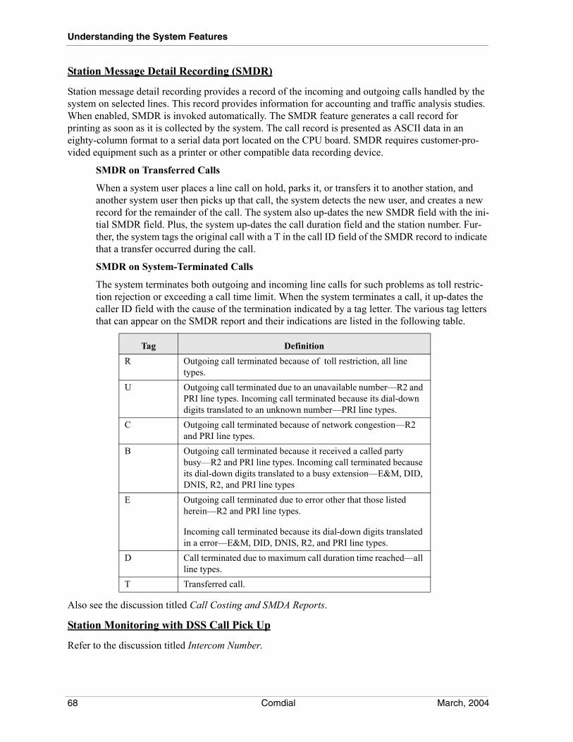
Understanding the System Features
Station Message Detail Recording (SMDR)
Station message detail recording provides a record of the incoming and outgoing calls handled by the system on selected lines. This record provides information for accounting and traffic analysis studies. When enabled, SMDR is invoked automatically. The SMDR feature generates a call record for printing as soon as it is collected by the system. The call record is presented as ASCII data in an eighty-column format to a serial data port located on the CPU board. SMDR requires customer-pro-vided equipment such as a printer or other compatible data recording device.
SMDR on Transferred Calls
When a system user places a line call on hold, parks it, or transfers it to another station, and another system user then picks up that call, the system detects the new user, and creates a new record for the remainder of the call. The system also up-dates the new SMDR field with the ini-tial SMDR field. Plus, the system up-dates the call duration field and the station number. Fur-ther, the system tags the original call with a T in the call ID field of the SMDR record to indicate that a transfer occurred during the call.
SMDR on System-Terminated Calls
The system terminates both outgoing and incoming line calls for such problems as toll restric-tion rejection or exceeding a call time limit. When the system terminates a call, it up-dates the caller ID field with the cause of the termination indicated by a tag letter. The various tag letters that can appear on the SMDR report and their indications are listed in the following table.
Also see the discussion titled Call Costing and SMDA Reports.
Station Monitoring with DSS Call Pick Up
Refer to the discussion titled Intercom Number.
Tag DefinitionR Outgoing call terminated because of toll restriction, all line
types.U Outgoing call terminated due to an unavailable number—R2 and
PRI line types. Incoming call terminated because its dial-down digits translated to an unknown number—PRI line types.
C Outgoing call terminated because of network congestion—R2 and PRI line types.
B Outgoing call terminated because it received a called party busy—R2 and PRI line types. Incoming call terminated because its dial-down digits translated to a busy extension—E&M, DID, DNIS, R2, and PRI line types
E Outgoing call terminated due to error other that those listed herein—R2 and PRI line types.
Incoming call terminated because its dial-down digits translated in a error—E&M, DID, DNIS, R2, and PRI line types.
D Call terminated due to maximum call duration time reached—all line types.
T Transferred call.
68 Comdial March, 2004
MP5000 I&M Manual - Volume 1
Station Name
The installer can assign a display name and a full name to a station. A display name is composed of a maximum of seven characters and shows in the display of an LCD speakerphone as a identification aid. A full name is composed of a maximum of 20 characters and shows in some voice mail and open architecture interface applications. The installer can compose a valid name from any alpha-numeric character; however, the first character of a display name must be an alphabetic character.
Station Speed Dial
Station speed dialing is a feature that lets the user dial lengthy numbers using one or two buttons, store frequently used feature dialing codes, and store intercom extension numbers of frequently called tele-phones. The user can store speed dial numbers at any unused programmable button, or if the installer assigns a shift button to a telephone, or one exists as a fixed feature button, the user can store a speed dial number at a second level under any programmable button.
Speed dial buttons can store up to 16 digits, plus line or intercom number selection. Stored digits include 0–9, * and #. A pause is stored at any point where the Hold button is pressed, and a hookflash is stored at any point where the TAP button is pressed. The system ignores any leading pauses entered prior to any digits but it processes all other pauses that the user generates with the Hold button. (Also refer to the discussion titled Automatic Pause Insertion.)
There are two levels of storage on speed dial buttons. To access the second level, the user must press the programmed Shift button. The shift mode is then active for five seconds after the Shift button is pressed. If a Shift button is not available, the user has access to only one level of speed dial storage.
A speed dial set is a group of 10 speed dial locations. The Impact FXII allocates one speed dial set to each telephone as a default but can allocate up to 10 sets to a telephone if a installer makes it so. When a DSS/BLF Console is operated as a companion to a telephone, the installer must allocate it’s speed dial sets at the companion telephone to be shared with the console. The total system speed dial allo-cation that is available is 960 sets or 9600 individual speed dial locations.
Station Transfer Recall
Refer to the discussion titled Timed Recall.
Subdued Off-Hook Voice Announce (SOHVA)
With the subdued off-hook voice announce (SOHVA) feature, a subdued announcement can be made from one station to another station that is off-hook and busy on a call. When a user is operating a tele-phone in a handsfree mode, it cannot receive a SOHVA. The telephone must be a model that includes SOHVA capability. With SOHVA, the announcement is delivered and responded to in a subdued manner that prevents the distant party from hearing either the announcement or the response. A tone alert precedes the announcement and is delivered to the handset receiver of the telephone ahead of the announcement. The installer can program the number of tones that the system delivers. The announcing callers also receive a tone to alert them that they are making a SOHVA call. Users can response to the announcement in a verbal or non-verbal manner. They affect a verbal response by pressing and holding the Mute button or appropriate interactive button and speaking into the handset. They effect non-verbal response by pressing a pre-programmed button to send a message to be shown on the display of the announcing station (if it is an LCD speakerphone). The announcing station is automatically disconnected after the response message is displayed. Stations that have the voice announce blocking feature turned on cannot receive a SOHVA call. Also refer to the discussion titled Call Announce with Handsfree Answer-back and Response Messaging.
March, 2004 Comdial 69
Understanding the System Features
SOHVA installations for analog telephones requires two paired station ports. In addition to the wiring connections associated with the installation, the installer must take certain programming actions. He or she must mark the telephone type for the odd-numbered station port to support the connected tele-phone, and mark the telephone type for the even-numbered station port undefined.
Busy on SOHVA
A default, a system returns a ring back tone to users who make SOHVA calls to busy stations; however, the system installer can arrange for telephone users to receive a busy signal instead of the ring back tone. This feature lets non-LCD telephone users know that a called station is busy.
SOHVA Beeps (SOHVA Tone Bursts)
Installers can choose the number of tone bursts that each telephone user hears preceding a SOHVA message to be a value of from one to six.
Subdued Off-Hook Voice Announce Groups
The SOHVA calling groups control the pattern that station ports receive and/or originate SOHVA calls to one another. The installer first creates SOHVA groups and then assigns individ-ual stations to each group.
Subdued Ringing
When a station is busy on a call and another call comes to the same station, the ringing of the second call will automatically be subdued to a lower volume.
Synchronized Ringing
When the installer enables synchronized ringing, the central office ringing pattern is tracked on external calls that ring within the Impact FXII.
Also refer to the discussion titled Discriminating Ringing.
System Clock
The system clock provides time and date information for display on LCD speakerphones and on SMDR/SMDA printouts. The clock also provides the time for the user-set alert feature.
System Speed Dial
System speed dialing provides system users with a repertory of up to 2000 numbers that they can dial from any telephone in the system. The installer or the attendant is responsible for storing the system speed dial numbers. These numbers can be up to 32 digits long and can include line number selection, the dial pad digits 0-9, *, and #, plus pauses and hookflash signals.
The installer or attendant can divide the unused or available system speed dial numbers into up to 50 different groups with up to 40 numbers in each group and then assign different speed dial groups to each station class of service.
The program can choose a line group that the system will automatically select for speed dialing. Alter-nately, the installer or attendant can choose the intercom to be automatically selected for speed dialing. This enhancement allows an intercom selection and feature codes to be stored together as speed dial numbers for true one-button access to features (for example; store Intercom *11 and Intercom #1 at two locations for system wide availability to music on and music off). This enhancement will not accept *#0* or *#746* as programming entries and it ignores any entered pauses or hookflashes.
70 Comdial March, 2004
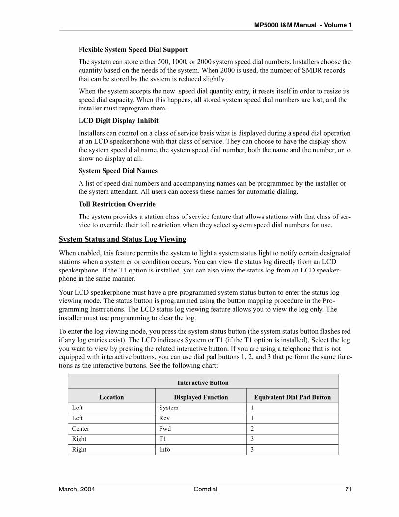
MP5000 I&M Manual - Volume 1
Flexible System Speed Dial Support
The system can store either 500, 1000, or 2000 system speed dial numbers. Installers choose the quantity based on the needs of the system. When 2000 is used, the number of SMDR records that can be stored by the system is reduced slightly.
When the system accepts the new speed dial quantity entry, it resets itself in order to resize its speed dial capacity. When this happens, all stored system speed dial numbers are lost, and the installer must reprogram them.
LCD Digit Display Inhibit
Installers can control on a class of service basis what is displayed during a speed dial operation at an LCD speakerphone with that class of service. They can choose to have the display show the system speed dial name, the system speed dial number, both the name and the number, or to show no display at all.
System Speed Dial Names
A list of speed dial numbers and accompanying names can be programmed by the installer or the system attendant. All users can access these names for automatic dialing.
Toll Restriction Override
The system provides a station class of service feature that allows stations with that class of ser-vice to override their toll restriction when they select system speed dial numbers for use.
System Status and Status Log Viewing
When enabled, this feature permits the system to light a system status light to notify certain designated stations when a system error condition occurs. You can view the status log directly from an LCD speakerphone. If the T1 option is installed, you can also view the status log from an LCD speaker-phone in the same manner.
Your LCD speakerphone must have a pre-programmed system status button to enter the status log viewing mode. The status button is programmed using the button mapping procedure in the Pro-gramming Instructions. The LCD status log viewing feature allows you to view the log only. The installer must use programming to clear the log.
To enter the log viewing mode, you press the system status button (the system status button flashes red if any log entries exist). The LCD indicates System or T1 (if the T1 option is installed). Select the log you want to view by pressing the related interactive button. If you are using a telephone that is not equipped with interactive buttons, you can use dial pad buttons 1, 2, and 3 that perform the same func-tions as the interactive buttons. See the following chart:
Interactive Button
Location Displayed Function Equivalent Dial Pad ButtonLeft System 1Left Rev 1Center Fwd 2Right T1 3Right Info 3
March, 2004 Comdial 71
Understanding the System Features
After selecting the log you want to view, you can view the time and date of the current log entry by pressing the Info interactive button (or dial pad button 3 when appropriate). You can scroll through the selected log to view all of the entries by pressing the Rev and Fwd interactive buttons (or dial pad buttons 1 and 2 when appropriate).
The number of entries in the log is displayed whenever you press the # button.
You exit the log viewing mode either by pressing the Speaker button, pressing the hookswitch, or waiting for the 15-second time-out.
System to System Networking
System to system networking connects several systems together in an arrangement that allows unified communications through the system. Refer to Comdial publication IMI89-280, for a complete description of this feature.
The communications network consists of one system acting as the hub and the remaining systems serving as nodes. The network allows up to 14 nodes as long as the 240 line limitation is not exceeded. The hub and all nodes MUST be using the same software release and the same feature sets. Any node can use either traditional FXNET (PRI) or FXVOIP (IP) networking. Only 10 nodes will be available if all are traditional or non-IP networking, since the maximum system capacity is 240 lines (10 times 24 channels). By using at least some FXVOIP boards, incremental channel assignments can be allo-cated to individual nodes, thus allowing the increased node support.
TT1 Digital Carrier Transmission Option
(for Domestic U.S.A. Applications)
The T1 digital carrier transmission option is a domestic U.S.A. option that allows up to 24 channels of voice and/or data transmissions over a single four-wire cable using multiplexing techniques in super-frame (SF) or extended superframe (ESF) format. For convenience, a customer service unit (CSU) is built into the T1 option board to terminate the T1 channels, provide protection from transient voltages, and respond to loopback requests from the central office.
TAP (Flash)/Recall
When host system custom calling features are available via a hook-flash signal while on line, the TAP button functions as a hook-flash button and generates a flash signal when the user presses it. When custom calling signals are not available, the TAP button functions as a positive disconnect and recalls dial tone when the user presses it. These features are mutually exclusive. The installer sets the desired function for the system by programming action. With single–line proprietary telephones, the Tap function works for internal transferring only. An access code is required to activate custom calling fea-tures.
Telephony Services Application
Programming Interface (TSAPI) Support
72 Comdial March, 2004
MP5000 I&M Manual - Volume 1
The FXII provides support for TSAPI applications. These applications are Novell Telephony Services* applications developed by third-party software vendors. TSAPI applications run independently of the FXII yet use its digital communications capability. The FXII’s Enterprise open architecture interface (OAI) data port provides the hardware interface for the personal computer (PC) that runs the TSAPI software program. Depending upon the TSAPI application and its functions, there may or may not be a need to reprogram the FXII’s database feature parameters.
*Novell, Novell NetWare, and Novell Telephony Services are registered trademarks of Novell Inc. Orem, UT
Through Dialing
An installer can connect external telephony equipment to the FXII through a proprietary interface device or through an IST port. When the installer enables the through dialing feature, DTMF tones that the external device generates pass through the interface equipment, the Impact FXII, and any line con-nection.
Time and Date
The time designation is in a 12-hour format. Time and date appear on the LCD speakerphone and the SMDA/SMDR record printout.
Timed and Immediate Recall
If a telephone user places a call on hold and fails to pick it back up within a preprogrammed time, the call rings the user’s telephone again. While only the telephone that put the call on hold rings, all other telephones that share call appearance will flash the light for the held call at a hold recall rate.
Recall to an originating station also occurs from unanswered parked calls, transferred calls, and calls that are camped-on. Plus, unanswered calls (ring no-answer calls) recall to the attendant or other pre-programmed designation after exceeding a preprogrammed time-out period.
Any transfer attempt that fails will cause the held call to recall immediately. Examples of failed transfer attempts are calling any of the following:
• non-existent extension,
• partial extension number,
• invalid extension number.
A calling party continues to hear music on hold (if provided) throughout the recall sequence.
Also, refer to the paragraph titled Hold Recall Inhibit.
Toll Restriction
With the toll restriction feature, the system allows or denies outgoing line calls to selected users over selected lines. Toll restriction meets different dialing needs by allowing users to dial numbers that they are required to dial yet restrict them from dialing numbers they are not allowed to dial. Toll restriction can be used together with the automatic route selection and call costing features if desired, or used sep-arately as a stand alone feature or not used at all.
March, 2004 Comdial 73
Understanding the System Features
The installer assigns toll restriction to stations based on system requirements. Telephones that are not assigned this feature are free to dial any number their users choose to dial. Plus, a toll restricted station can dial any telephone number that it is not restricted from dialing. If a station is restricted from dialing a certain telephone number on a certain line, it can, if programming permits, dial that number on another line that is not restricted. Further programming action specifies whether or not toll restriction applies to system speed dial numbers. The installer can also differentiate between day toll restrictions and toll restrictions that only take effect in night mode. A defaulted system imposes no toll restriction on any station.
The toll restriction feature first compares a dialed number to a matching assigned restricted number up to the last digit in the assigned number. At that point it considers it a match and applies other toll restriction tests whether the station user keeps dialing or not. If all toll restriction tests are met, the station is not normally allowed to dial the number. There are 32 exception number test matches assigned to the station. Exception numbers allow stations to dial numbers that they are not normally allowed to dial by their toll restriction.
Toll Restriction Pause Entries
When this feature is activated by installers, they can enter a pause at the end of a restricted number’s digit string to indicate that dialing is complete. They do this by typing a P after they type the digit string. The pause entry distinguishes this restricted number as unique. They can enter the same digits without the pause but instead followed by additional digits as another unique number. They can assign different routing and toll restriction parameters to each of these entries. There are several applications for this feature. One application is in international dialing where different toll restriction parameters apply depending upon whether the caller dialed 0 or 011. In this case, installers can enter 0 pause to access local lines and 01 to access international lines. Another application is with tie line calling where a remote extension is the same digits as an office or area code that installers need to enter in the restriction table. By entering nnn pause for tie line access and nnn@ for CO line access, the system can route the call over the proper line. A third application is brought forth with the advent of the new North American Numbering Plan (NANP). With NANP, an area code may be the same digits as a local office code. Installers can enter nnn@@@@ pause for local line access and nnn@@@@@@@ for long dis-tance line access (the @ is a match anything character). In any application, the system resets its pause timer after receiving each caller dialed digit. If the timer expires before the caller dials another digit, the system routes the call based on the digits preceding the pause. If, instead, the system detects more digits instead of a pause, it routes the call based on the entire digit string.
Tone on Hold
This feature gives you an alternative to providing music or no music for callers who are placed on hold.
When you program this feature into the Impact FXII, both internal and external callers hear a pattern of short tone bursts while they are on hold. The patterns consist of two 1/10-second tone bursts separated by 1/10-second. These tone patterns repeat every five seconds.
The installer enables this feature and assigns it to particular lines through line programming or stations through class of service programming using the PC. The system manager can also select this feature from the applicable class of service from a programming station for intercom calls placed on hold. The choices when programming this feature are: music from source one, music from source 2, tone on hold, or nothing.
74 Comdial March, 2004
MP5000 I&M Manual - Volume 1
Tone or Voice Signaling on Internal Calls
Intercom number calls can be tone signaled or voice signaled as desired. Programming determines which signaling method the system uses as the primary method when an intercom number call is made. Users can choose the alternate method at the station by pressing the intercom key. Intercom number call progress is marked by special tone signals.
Tracker Paging System
The Tracker Paging System interfaces a Impact FXII with individual Tracker pagers. The Tracker Paging System informs users through their Tracker pagers that they have a call waiting for them. The Tracker base station connects to any of the Impact FXII’s serial ports or to the PC Attendant position. The FXII can accept up to four Tracker base stations supporting up to 600 Tracker pagers. Many dif-ferent types of Tracker pagers are supported—from those with numeric displays to those that display a pre-programmed message up to 32 alphanumeric characters long.
Creating Messages from the PC Attendant
Up to eight default messages can be programmed and delivered from the PC Attendant position only (see the Digital Communications System PC Attendant’s Console User’s Guide, GCA70–230 for instructions). The PC attendant can be in either the Local or the System mode of operation.
RNA or Busy Tracking
If the called station fails to answer or is busy, the caller can activate the Tracker Paging System by pressing the Track button on his or her telephone. The Track button is one of the telephone’s inter-active buttons. On telephones not equipped with interactive buttons, the caller activates the Tracker Paging System by dialing the Tracker access code (defaults to *8). When the call is accepted, the caller will hear a confirmation tone, or if it is not accepted, a busy tone.
Direct Tracking
The caller can also do direct paging by pressing the Track programmed button or by dialing the Tracker access code (defaults to * 8). The telephone prompts the caller with its display to enter the assigned extension number for the pager along with the display message Enter Ext:
Transfer Tracking
If the system attendant attempts to transfer a call to an extension that does not answer (or is busy) and then activates the Tracker pager assigned to that extension, the incoming call is placed on a page orbit. Once the system places the call on a page orbit, the user’s Tracker pager displays the orbit number so that he or she can retrieve the call by dialing the number of the orbit containing the call. If the user does not retrieve the call within the pre-programmed time-out, the call returns to the attendant. The Tracker Paging System supports up to 100 page orbits.
Using Voice Mail with Tracking
When a caller reaches an extension with an assigned Tracker pager, and that extension is covered by proprietary voice mail, the system may prompt the caller to either select the assigned Tracker pager or leave a message. If the caller selects the Tracker pager, the system places the call in a page orbit, and displays that page orbit number on the user’s Tracker pager. The user retrieves the call by dialing the number of the page orbit containing the call. After a pre-programmed time-out, the call is returned to the proprietary voice mail where the caller can leave a message.
March, 2004 Comdial 75
Understanding the System Features
Accessing the Tracker Pager From DISA
The Tracker Paging System is accessible from DISA by using the DVA voice messages.
Programming Options
There are three levels of programming associated with Tracker operation.
The installer or installer performs the Impact FXII level using a PC. Programming at this level installs Tracker operating parameters and pager-to-intercom assignments that can only be changed at this pro-gramming level.
The PC attendant level of programming, available when the PC attendant position is installed, operates in one of two modes–local or system. In the local mode, the attendant assigns pagers to intercoms and selects pager types. This programming is transparent to the Impact FXII and does not alter any Tracker programming done at the Impact FXII level. In the system mode of operation, all Tracker operating parameters and pager-to-intercom assignments are as programmed into the Impact FXII by the installer or system installer.
The system manager level of programming allows the system administrator to use a programming station to select a Tracker base station and enable or disable the Tracker Paging system.
Transfer/Conference Button
Each multiline telephone and proprietary multiline telephone provides a fixed button that gives quick, easy transferring and conferencing of calls.
Transfer Recall
Refer to the discussion titled Timed Recall.
Transfer Ring Cadence
A telephone user can select the ringing cadence that announces a transferred line call. They have two choices as follows: one cadence provides a 2 sec. on—4 sec. off tone, the other cadence provides a 0.5 sec on—5.5 sec. off tone. The installer can choose either cadence as the default setting.
UUnscreened Call Transfer
Refer to the discussion titled, Call Transfer–Unscreened With Automatic Camp-On.
Unsupervised Conference
Refer to the discussion titled Conferencing—Multiline.
VVideo Call
This feature permits Softphone users equipped with a PC camera, the ability to conduct video commu-nications with other Softphone users also equipped with a PC camera. The PCs engaged in a Video Call must be running Microsoft Windows XP.
76 Comdial March, 2004
MP5000 I&M Manual - Volume 1
Voice Mail Integration Digits
Installers can choose the DTMF digits that the FXII sends to a voice mail system. A voice mail system uses these DTMF digits to determine system and station status so that it can properly process a call. Installers must be versed in the voice mail’s requirements before they can assign DTMF integration digits in the FXII. The system defaults the voice mail parameters to match the Comdial voice mail system. Certain applications in countries with dialing plans different than the United States may require different integration digits. The default digits are shown in the following list and discussed below:
Follow Extension ID—When the voice mail system receives a forwarded call from a ring no-answer (RNA) or busy station, the FXII sends to the voice mail system the extension number of the forwarded call followed by this DTMF digit (n). The FXII sends this digit within 500 ms of the time the voice mail system answers the call. For example, if extension 101 is forwarded to voice mail and voice mail answers a forward RNA or busy forwarded call, the FXII sends 101n to the voice mail system within 500 ms of the answer time.
Intercom/Answer Confirmation—The FXII sends this DTMF digit to the voice mail system to confirm that an intercom path (without dial tone) is available for the voice mail system’s call transfer or dialing use. The FXII sends this digit within 500 ms of the time it detects the voice mail system’s off-hook or hookflash condition. The FXII also immediately sends this digit to the voice mail system when a station answers a voice mail transferred call. This action can alert the voice mail system to dis-connect and leave the parties connected.
Busy—If the voice mail system transfers a call to a station that is busy on a call, the FXII sends this DTMF digit to the voice system. When the voice mail system receives this digit, it can abandon the transfer, reconnect to the call, and offer the caller whatever options the voice mail system has available in its programming. If the FXII auto attendant transfer on busy feature is active, the FXII will not send the DTMF digit to the voice mail system thus allowing the system to transfer a second call to the station.
DND—If the voice mail system transfers a call to a station that is in the do not disturb (DND) mode, the FXII sends this DTMF digit to the voice system. Receiving this digit allows the voice mail system to distinguish between a busy and a DND condition and offer the caller the appropriate choices.
Incoming Intercom Answer—The FXII sends this DTMF digit to the voice mail system when a station user makes an intercom call to the voice mail system. This action allows the voice mail system to distinguish between internal and external calls and offer the caller appropriate prompts and dialing options.
Disconnect—When an outside line or intercom party hangs up, the FXII sends this DTMF digit to the voice mail system to command an immediate disconnect. For outside calls, the central office (CO) must provide disconnect supervision to the FXII and the installer must program the FXII line for abandon hold release and disconnect supervision. At default, the FXII sends the DTMF tone for the A character as the disconnect digit. Since a caller cannot dial an A from a telephone. This feature elimi-nates callers from causing an accidental disconnect by dialing this digit on their telephone’s dial pad.
Follow Extension ID = 2 Intercom/Answer Confirmation = 1Busy = 2 Do Not Disturb = 3Incoming Intercom Answer = 2 Disconnect = 2
March, 2004 Comdial 77
Understanding the System Features
Voice Announce Blocking
This feature allows the user of multiline telephones to block voice announced intercom calls by dialing a special code or by pressing a programmed button.
VMMI Backwards Compatibility Enhancement
VMMI software can program earlier versions of the common code base (CCB) databases in both on- and off-line modes of operation and leave that software at its earlier revision. The earliest versions of CCB software affected by this enhancement is software release 12A. This means the latest version of VMMI can program databases created with software releases as early as 12A without upgrading that software to the latest revision. With this enhancement, an installer can load a new version of VMMI programming anytime without disrupting existing programmed databases.
It is important to understand that when installers program older revision software database files with this current revision VMMI, the newer VMMI will blank and disable any new features that do not apply to the older revision software. For example, when using 13A revision VMMI to program a 12A software revision database file, installers will not be able to use the controls resident in the IST Board Programming dialog. However, if the installers translate the database to revision 13A, these controls are enabled for programming.
Voice over IP (VoIP)
This feature provides station-to-station calling between systems that are running the Internet Protocol (IP) networking software. Combining the features of the IP networking software, and the intercon-nection provided by the VoIP boards, telephone voice, facsimile (FAX) relay, and data modem commu-nications are available between several widely-separated systems through the same site-supplied Wide Area Network (WAN) configuration that handles the data traffic for the site.
Call handling features available to telephone callers over the IP network are the same as those pro-vided by the conventional system-to-system networking features.
This feature requires the addition of a VoIP board (p/n FXVOIP-S or FXVOIP-L) installed in any uni-versal slot and connected directly to the network router or to a WAN connection.
ZZone Paging
This feature arranges for stations to transmit and/or receive voice announcements to and from a par-ticular group of stations or to all stations. This feature also arranges for all-call and zone paging to an external paging device. The installer can assign stations to particular paging zones, up to eight zones, to permit station users to make announcements to one particular site, or he or she can assign all stations to the same zone to permit users to announce all areas at once.
78 Comdial March, 2004
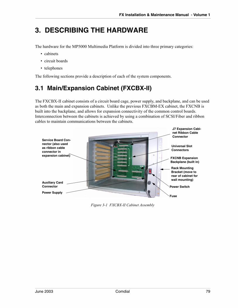
FX Installation & Maintenance Manual - Volume 1
3. DESCRIBING THE HARDWARE
The hardware for the MP5000 Multimedia Platform is divided into three primary categories:
• cabinets
• circuit boards
• telephones
The following sections provide a description of each of the system components.
3.1 Main/Expansion Cabinet (FXCBX-II)
The FXCBX-II cabinet consists of a circuit board cage, power supply, and backplane, and can be used as both the main and expansion cabinets. Unlike the previous FXCBM-EX cabinet, the FXCNB is built into the backplane, and allows for expansion connectivity of the common control boards. Interconnection between the cabinets is achieved by using a combination of SCSI/Fiber and ribbon cables to maintain communications between the cabinets.
Figure 3-1 FXCBX-II Cabinet Assembly
J7 Expansion Cabi-net Ribbon Cable Connector
Power Switch
Fuse
Auxiliary Card Connector
Service Board Con-nector (also used as ribbon cable connector in expansion cabinet)
Universal Slot Connectors
FXCNB ExpansionBackplane (built in)
Rack Mounting Bracket (move to rear of cabinet for wall mounting)
Power Supply
June 2003 Comdial 79
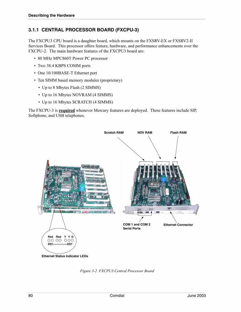
Describing the Hardware
3.1.1 CENTRAL PROCESSOR BOARD (FXCPU-3)
The FXCPU3 CPU board is a daughter board, which mounts on the FXSRV-EX or FXSRV2-II Services Board. This processor offers feature, hardware, and performance enhancements over the FXCPU-2. The main hardware features of the FXCPU3 board are:
• 80 MHz MPC860T Power PC processor
• Two 38.4 KBPS COMM ports
• One 10/100BASE-T Ethernet port
• Ten SIMM based memory modules (proprietary)
• Up to 8 Mbytes Flash (2 SIMMS)
• Up to 16 Mbytes NOVRAM (4 SIMMS)
• Up to 16 Mbytes SCRATCH (4 SIMMS)
The FXCPU-3 is required whenever Mercury features are deployed. These features include SIP, Softphone, and USB telephones.
Figure 3-2 FXCPU3 Central Processor Board
Ethernet Connector
Flash RAMNOV RAMScratch RAM
COM 1 and COM 2 Serial Ports
Ethernet Status Indicator LEDs
Red Red Y Y G
DS1---------------DS7
80 Comdial June 2003
FX Installation & Maintenance Manual - Volume 1
Status Indicators
As shown in Figure 3-4, the FXCPU-3 contains a row of LED status indicators for the Ethernet connection. These LEDs are numbered DS1 through DS7.
• DS1: HDX (Red LED)-On when board operates in half duplex
• DS2: FDX (Red LED)-On when board operates in full duplex
• DS3: 10Base-TX (Red LED)-On when service is active
• DS4: 100Base-TX (Red LED)-On when service is active
• DS5: TXD (Yellow LED)-Winks on with transmit data
• DS6: RXD (Yellow LED)-Winks on with received data
• DS7: Link (Green LED)-Turns on when Ethernet com link is established
The Ethernet status lights are useful to verify a functioning Ethernet connection. The LINK LED indicates a functioning network connection at the data speed indicated by either the 10Base-T or 100Base-TX LEDs. The other status lights indicate transmit and receive data, full or half duplex operation.
Programming Requirements
New programming options for the CPU-3 include:
1. Board’s IP Address. The IP address of the CPU board’s Ethernet port.2. Network Mask. The Network Mask of the CPUs Ethernet port.3. Gateway. The IP address of the gateway router.4. Domain Name for System. (32 characters)5. Administrator’s Email Address. (64 characters)6. Alerts. Set the level of alerts. Choices “None”, “Reset Only”, “All”. Default is None.7. SIP Programming
(a) SIP Endpoint Provisioning.
(b) SIP Registration Authorization.
(c) SIP Registration Expiration Value.
3.1.2 FXCPU3 MEMORY UPGRADES
Memory for the FXCPU-3 consists of proprietary 72-pin SIMM modules that are plugged into slots on the CPU board. Each SIMM provides 4 Mbytes of memory capacity. These slots are designated as Flash memory (two slots), NOV RAM memory (four slots), and Scratch memory (four slots).
• Flash: Programmable, non-volatile program storage. This memory holds the bootloader software responsible for basic hardware initialization and the FX system software. The FX system software can be upgraded by the user through the VMMI programming interface.
• Scratch: Random Access Memory used as dynamic storage for general system processing.
June 2003 Comdial 81
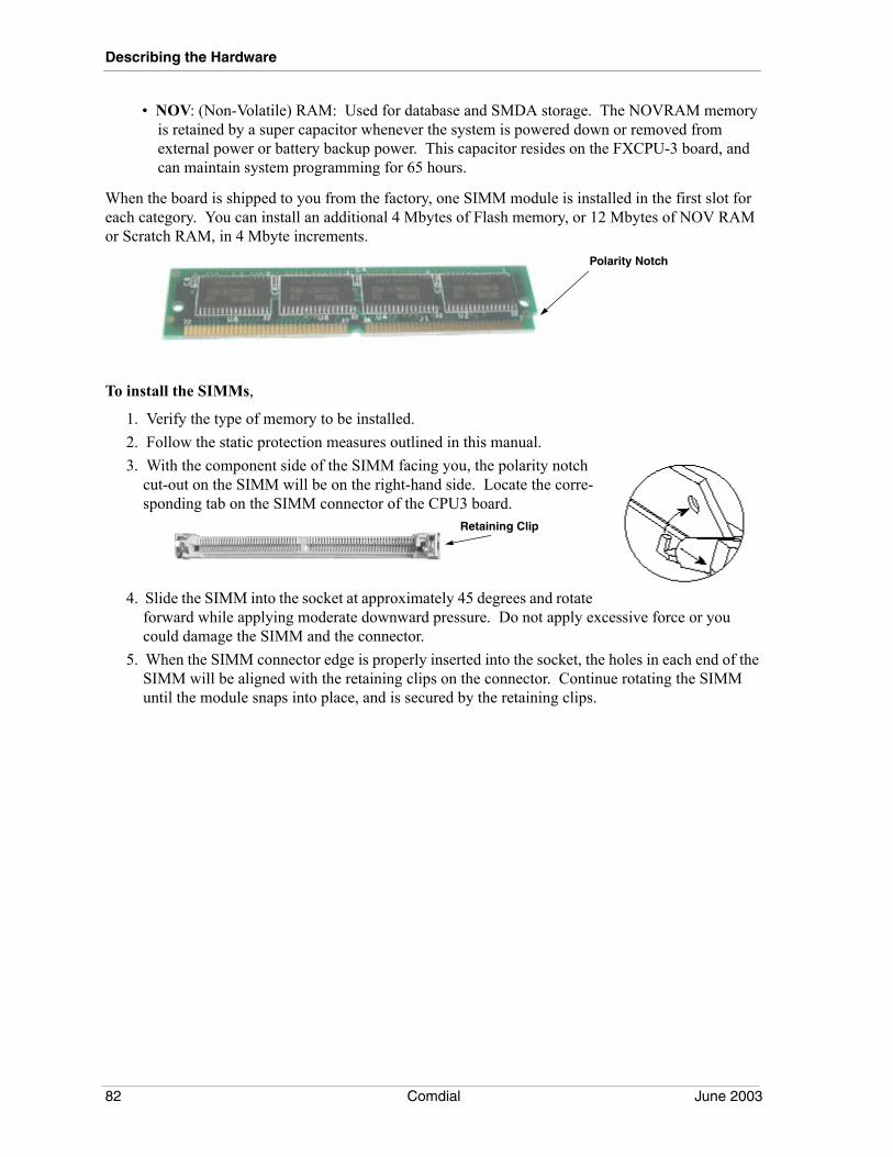
Describing the Hardware
• NOV: (Non-Volatile) RAM: Used for database and SMDA storage. The NOVRAM memory is retained by a super capacitor whenever the system is powered down or removed from external power or battery backup power. This capacitor resides on the FXCPU-3 board, and can maintain system programming for 65 hours.
When the board is shipped to you from the factory, one SIMM module is installed in the first slot for each category. You can install an additional 4 Mbytes of Flash memory, or 12 Mbytes of NOV RAM or Scratch RAM, in 4 Mbyte increments.
To install the SIMMs,
1. Verify the type of memory to be installed.2. Follow the static protection measures outlined in this manual.3. With the component side of the SIMM facing you, the polarity notch
cut-out on the SIMM will be on the right-hand side. Locate the corre-sponding tab on the SIMM connector of the CPU3 board.
4. Slide the SIMM into the socket at approximately 45 degrees and rotate forward while applying moderate downward pressure. Do not apply excessive force or you could damage the SIMM and the connector.
5. When the SIMM connector edge is properly inserted into the socket, the holes in each end of the SIMM will be aligned with the retaining clips on the connector. Continue rotating the SIMM until the module snaps into place, and is secured by the retaining clips.
Polarity Notch
Retaining Clip
82 Comdial June 2003
FX Installation & Maintenance Manual - Volume 1
3.1.3 SERVICES BOARD (FXSRV2-II OR FXSRV-EX)
The Services board (FXSRV-EX or FXSRV2-II) provides an interface for music-on-hold and background music inputs; it also provides an output to an external paging amplifier. This board also includes a 512K timeswitch for making all station to station and line to line voice connections in the system. The FXSRV2-II is required for a multi-cabinet installation.
This board includes:
• 1 DTMF receiver
• 4 Programmable dry-contact relays
• 1 six-pin modular connector: For two Music on Hold inputs and one paging output port
• 8 Dipswitches: Switch 1 controls the connection speed on FXCPU-2 communications portWhen switch 1 is in the down position (on) the communication ports on the CPU board are:Port 1: 2400 baudPort 2: 9600 baud
Switch 8: Used for master clearing
• 1 internal remote maintenance modem
3.1.4 EXTERNAL BATTERY ASSEMBLY (BBLFXII)
The external battery assembly is for use with the FX II digital communication system. It provides power to the equipment during those times when AC power to the site is interrupted. Should the AC power be interrupted, the external battery assembly provides one hour of operation for a fully loaded system
The FX II External Battery Assembly can be rack mounted just below the cabinet. The package for the battery backup unit contains brackets to support either wall or rack mounting.
June 2003 Comdial 83
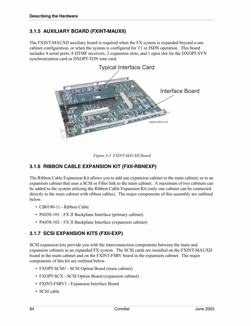
Describing the Hardware
3.1.5 AUXILIARY BOARD (FXINT-MAUXII)
The FXINT-MAUXII auxiliary board is required when the FX system is expanded beyond a one cabinet configuration, or when the system is configured for T1 or ISDN operation. This board includes 4 serial ports, 8 DTMF receivers, 2 expansion slots, and 1 open slot for the DXOPT-SYN synchronization card or DXOPT-TON tone card.
Figure 3-3 FXINT-MAUXII Board
3.1.6 RIBBON CABLE EXPANSION KIT (FXII-RBNEXP)
The Ribbon Cable Expansion Kit allows you to add one expansion cabinet to the main cabinet, or to an expansion cabinet that uses a SCSI or Fiber link to the main cabinet. A maximum of two cabinets can be added to the system utilizing the Ribbon Cable Expansion Kit (only one cabinet can be connected directly to the main cabinet with ribbon cables). The major components of this assembly are outlined below.
• CB0190-11 - Ribbon Cable
• PA058-101 - FX II Backplane Interface (primary cabinet)
• PA058-102 - FX II Backplane Interface (expansion cabinet)
3.1.7 SCSI EXPANSION KITS (FXII-EXP)
SCSI expansion kits provide you with the interconnection components between the main and expansion cabinets in an expanded FX system. The SCSI cards are installed on the FXINT-MAUXII board in the main cabinet and on the FXINT-FSRV board in the expansion cabinet. The major components of this kit are outlined below.
• FXOPT-SCM1 - SCSI Option Board (main cabinet)
• FXOPT-SCX - SCSI Option Board (expansion cabinet)
• FXINT-FSRV1 - Expansion Interface Board
• SCSI cable
Interface Board
expand6a.cdr
Typical Interface Card
84 Comdial June 2003
FX Installation & Maintenance Manual - Volume 1
3.1.8 FIBER OPTICS EXPANSION KITS (FXOPX-n)
The Fiber Optics card provides an optical interconnection between the main and expansion cabinets in an expanded FX system With the benefit of the fiber optic medium’s immunity to signal degradation or corruption, it provides a good alternative to the SCSI-driven electrical link used for the same purpose. The Optics cards are installed on the FXINT-MAUXII board in the main cabinet and on the FXINT-FSRV board in the expansion cabinet.
Fiber Optics support is system software keyed, and you must enable the software key before you can turn on Fiber Optics service at an installation site.
Systems normally do not ship from Comdial with the Fiber Optics cards installed. The Fiber Optics card is part of a field expansion kit that includes both a main and expansion Fiber Optics card and an expansion services board. The Comdial ordering code numbers for the Fiber Optics expansion kits are as detailed in the following table:
The Fiber Optics card provides a Power and Signal LED to indicate the status of the board. When illuminated, the Power LED indicates that power is applied to the card and the microprocessor is operating. When the Signal LED is illuminated, it indicates that the received signal is functional.
Kit Ordering Code Kit Contents
FXOPX-1 (1) FXOPT-FBM-1 main Fiber Optics board(1) FXOPT-FBX-1 expansion Fiber Optics board(1) FXINT-FSRV expansion services board (board includes eight DTMF receivers for system use when needed)
FXOPX-2 (1) FXOPT-FBM-1 main Fiber Optics board(1) FXOPT-FBX-1 expansion Fiber Optics board(1) FXINT-FSRV-1 expansion services board (board has no on-board DTMF receivers)
June 2003 Comdial 85
Describing the Hardware
3.1.9 LINE AND STATION BOARDS OVERVIEW
In the FX family of systems, all line and station boards are compatible between the various system types. All line and station boards have status lights and pre-charge jacks. The green LED on each board gives an indicator of the in-use status or proper operation of the board. See the chart below for more information on identifying a boards’s status.
The following conditions identify why the LED on a board may be in the steady-on state:
• The default common code software has not detected the board in the system. This generally happens when a new board cannot be detected by demo software prior to an initialization.
• The physical slot that the board is in actually contains a different board in VMMI programming.
• The board has been physically installed but not yet added to VMMI programming.
The precharge jack permits you to remove or install a line or station board while the system is operational. The FX II is equipped with a modular line cord that is attached to the power supply. Plug the end of the cable into the board’s pre-charge jack before removing or installing it in the system.
Board Type LED Status Indicator
Line Board Rapid Flash=Malfunctioning line board microprocessorOff with repeated 5 second blink on=Normal operation with all lines idle.On with repeated 5 second blink off=normal operation with at least one line busy.Steady On or Steady Off=Board Malfunction
Station Board Rapid Flash=Malfunctioning station board microprocessorOff with repeated 5 second blink on=Normal operation with all stations idle.On with repeated 5 second blink off=normal operation with at least one station busy.Steady On or Steady Off=Board Malfunction
86 Comdial June 2003
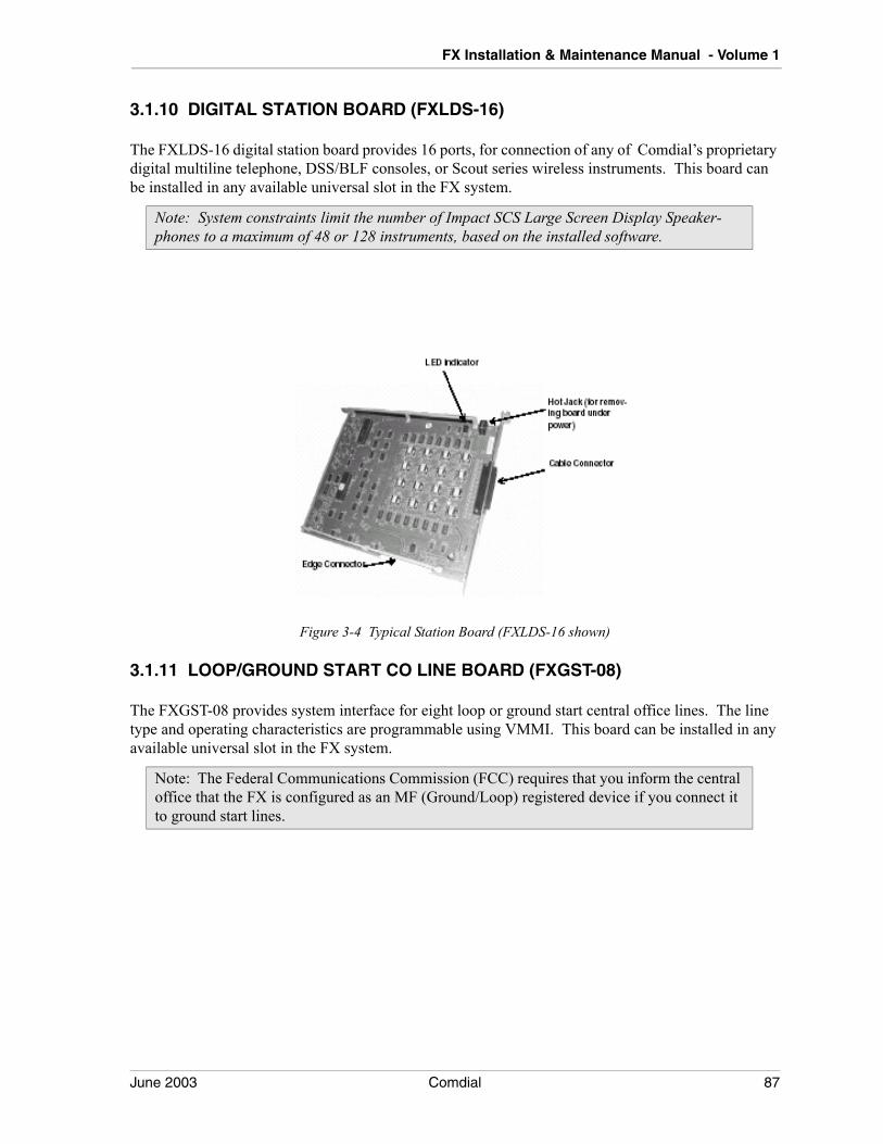
FX Installation & Maintenance Manual - Volume 1
3.1.10 DIGITAL STATION BOARD (FXLDS-16)
The FXLDS-16 digital station board provides 16 ports, for connection of any of Comdial’s proprietary digital multiline telephone, DSS/BLF consoles, or Scout series wireless instruments. This board can be installed in any available universal slot in the FX system.
Figure 3-4 Typical Station Board (FXLDS-16 shown)
3.1.11 LOOP/GROUND START CO LINE BOARD (FXGST-08)
The FXGST-08 provides system interface for eight loop or ground start central office lines. The line type and operating characteristics are programmable using VMMI. This board can be installed in any available universal slot in the FX system.
Note: System constraints limit the number of Impact SCS Large Screen Display Speaker-phones to a maximum of 48 or 128 instruments, based on the installed software.
Note: The Federal Communications Commission (FCC) requires that you inform the central office that the FX is configured as an MF (Ground/Loop) registered device if you connect it to ground start lines.
June 2003 Comdial 87
Describing the Hardware
3.1.12 CENTREX MESSAGE WAITING LINE BOARD W/CID (FXCMW-XX)
The FXCMW-08 and FXCMW-16 line boards provide eight and sixteen lines respectively, with support for caller ID and message waiting services provided by the central office. Message Waiting messages are indicated by a flashing LED button. LCD speakerphones present a list of waiting messages as well as caller ID information. This board can be installed in any available universal slot in the FX system.
System software release 193 or later should be used with these boards. For additional information on this boards functionality, see GCA40-301, General Description for Software Release 193.
3.1.13 DID/E&M LINE BOARD (FXEMDD-DF)
The DID/E&M line board supports eight DID and two E&M Tie Lines and can be installed in any available universal slot in the FX system.
Direct Inward Dial (DID) lines support only incoming calls and are used to reduce the number of channels between the FX system and the Central Office. The number of DID lines the system accepts is limited only by the number of DID/E&M line boards you install. The supported line types include Wink Start, Delay Start, or Immediate Start. With the addition of an add-on card, this board can be configured to support E911 line types.
The FX system supports two different types of tie lines. The direct type is for direct connection between two telephone systems and is also known as a metallic connection. The carrier type is for tie lines that run through a central office interface.
If you plan to use tone dial configured tie lines with the DID/E&M line board, you may need to instal one or more DTMF receiver cards. Typically, you will need one DTMF receiver for every six lines. In high traffic situations, you may need additional DTMF receivers. For information on DTMF receiver cards, see IMI89-185, Installing a DTMF Receiver in the Impact FX Digital Communications System.
3.1.14 T1 LINE BOARD (FXT1-24)
The FXT1-24 gives the FX system the capability to handle up to 24 channels of voice and/or data transmissions over a single four-wire cable using multiplexing techniques in superframe (SF) or extended superframe (ESF) format. The FXT1 board includes a customer service unit (CSU) to eliminate the need for a CSU external to the FX system.
The FXT1-24 board can be installed in any available universal slot in the FX system. Whenever you install one or more FXT1 boards and the FX system is receiving its timing signals from an external source, you must install one synchronization card (DXOPT-SYN) on the FXINT-MAUXII board. When you connect the system to central office lines, you must include a synchronization card, and the FX system must be controlled by CO signaling. In installations where the FX system supplies the clock signal for the distant system, there is no requirement for DXOPT-SYN cards.
88 Comdial June 2003
FX Installation & Maintenance Manual - Volume 1
If you plan to use tone dial configured DID or E&M lines with the T1 digital carrier transmission options, you may need to install one or more DTMF receiver cards to the FX system. Typically, you will need one DTMF receiver for every six lines. Remember, the CPU provides one onboard DTMF receiver cable of supporting six DID or E&M T1 lines. You may need to add one DTMF receiver card for each FXT1 board that is configured for 24 DID or E&M lines. For details on DTMF receiver card installation, see IMI890275, Installing a DTMF Card in the FX Digital Communications System.
3.1.15 FXNET BOARD (FXNET)
The FXNET board is essentially a T1 line board equipped with a primary rate interface (PRI) circuit card and special firmware that permits system to system networking. The FX network can be an intra-network joining several systems at a common site, or an inter-network joining several systems across a geographic area. The FXNET board uses a proprietary ISDN signaling protocol for communications between networked boards.
In addition to the FXNET board required at every system in the network, the common equipment at each node system requires a synchronization card (DXOPT-SYN). For on-site network functions not needing CO timing, the hub system does not require a DXOPT-SYN card.
When a service provider supplies the communication connections between the hub and the nodes, these connections must be PRI Clear Channel dedicated access lines for network use.
For a complete description of setting up a network with the FXNET board, refer to Comdial publication IMI89-280, Installing and Using System to System Networking.
3.1.16 SYNCHRONIZATION CARD (DXOPT-SYN)
The DXOPT-SYN card uses a reference timing frequency of 8KHz that it derives from the 1.544 MHz frequency supplied to the T1/RI board by the central office (CO) or other external source. By referencing this 8 KHz with 8 KHz timing derived internally, the master 16.384 MHz voltage-controlled oscillator (VCO) can be synchronized. The transmit clock (1.544 MHz) is derived from the 16.384 MHz frequency on the T1/PRI board.
3.1.17 ISDN-PRI INTERFACE LINE BOARD (FXT1-PRI)
Integrated Services Digital Network (ISDN) provides integrated voice and data over a common telephone company facility. ISDN-PRI provides a way for subscribers to get digital service from the telephone company supplier for 24 lines over two special pairs of wires.
ISDN-PRI access consists of a grouping of 23 voice channels (B-channels) and one signaling or control channel (D-channel). B-channels are clear channels suitable for voice or data transmission while the D-channel is a packet-switched link for call setup and signaling.
The DXPRI is a circuit card that you install on a FXT1-24 line board with special-purpose firmware to provide ISDN-PRI access to the digital communications system. The DXPRI card handles the D-channel signaling protocol and passes messages to the FXT1 board.
Note: The DTMF receiver cards that you add for this purpose are in addition to any you may add to the system to support industry-standard telephone station boards.
June 2003 Comdial 89
Describing the Hardware
Since central office protocols differ, the DXPRI card supports several protocol arrangements and provides interface support for several signaling types.
The DXPRI card provides a calling number identification (caller ID) feature that provides the following services: delivery of network-provided calling numbers, calling line identification presentation (CLIP), or automatic number identification (ANI). On originated calls, the system automatically provides the calling number if available. Otherwise, it provides the default directory number. For incoming calls, the called station displays the calling number if available; otherwise, the display shows information determined by station class of service programming. The system programmer can customize the caller ID parameters for outgoing calls as site requirements dictate.
The FXT1 board with special-purpose firmware serves as host for the DXPRI card and gives the digital communications system the capability to handle up to 23 channels of voice and/or data transmissions over a single four-wire cable using multiplexing techniques. These boards are packaged together as the FXT1-PRI line board.
3.1.18 IST STATION BOARD (FXISTM-CXX)
The FXISTM-C08 supports 8 industry-standard telephones with message waiting, DTMF receiver, and Caller ID support. The FXISTM-C16 supports 16 industry-standard telephones with message waiting, DTMF receiver, and Caller ID support. The FXISTM-Cxx can be installed in any available universal slot in the FX system.
Caller ID is a feature that allows information about a call originator to be displayed at the call receiver’s CID equipped IST telephone or other CID display device. CID information consists of the following items:
• date and time of the call (month, day, hour, minute)—the time being provided by the FX system clock when the system sends the CID data to the IST CID device.
• the caller’s number
• the caller’s name (if available)
The system only updates the CID information to the IST device while the device is on-hook and ringing. Therefore, incoming calls and recalls will update the IST CID display, but outgoing calls will not. If an unscreened transfer is made to an IST CID device connected to the FXISTM-Cxx board, the display updates to reflect the transferring station, and then updates again to reflect the transferred parties’ CID information. If the called party answers before the transferring station hangs up, the system cannot update the display to reflect the transferred parties’ CID information.
The FXISTM-Cxx contains one DTMF receiver for each station port. The availability of these on-board DTMF receivers means an FX system will not allocate a system DTMF receiver when a port on the FXISTM-Cxx board goes off hook. The on-board DTMF receivers are for exclusive use of the IST devices and are not available for use by the rest of the FX system.
Refer to Comdial publication GCA99-501, General Description for Software Release 192, Feature Set 17B, for a complete description of the FXISTM-Cxx.
90 Comdial June 2003
FX Installation & Maintenance Manual - Volume 1
3.1.19 VOIP LINE BOARD (FXVOIP-X)
The FXVOIP-S and FXVOIP-L is a multi-purpose media board, that is capable of supporting IP LAN/WAN networking, Voice over IP (VOIP), or Session Initiation Protocol (SIP). The boards function is assigned by downloading application specific firmware to the board and making the necessary programming assignments in VMMI. SIP functionality is only supported on systems that also include the CPU-III processor board.
Voice over Internet Protocol (VoIP) is based upon the principle of transmitting digitized voice packets over IP networks. VoIP consists of converting voice signals into streams of digital packets and sending those packets of data through an IP environment.
When installed to support networking, the FXVOIP-S and FXVOIP-L is a voice handling device that replaces the traditional line board in an FX system. The FXVOIP-S provides 0-12 voice channels and the FXVOIP-L provides 0-24 voice channels. These boards convert the telephone system’s control signalling and voice traffic into IP packets for transport over an IP network. By doing this the VoIP board and the IP network replaces the functions normally provided by a conventional T1 connection between networked systems.
The current Comdial system-to-system networking scheme dictates that the hub system contain at least one VoIP board for each node participating in the IP telephony arrangement. Each node system must contain at least one VoIP board to communicate with the hub system. While each VoIP board provides one end of a hub-to-node connection, you may need multiple boards to make the needed hub to node connections in installations involving high network traffic. Refer to Comdial publication IMI89-346, Installation and Programming for the VoIP Board.
The VOIP Line Board with General Purpose Media Board firmware installed, supports voice packet communication with SIP telephones. This board and firmware accesses up to 24 transmit voice channels from the FXCPU-3, converts each channel to a series of RTP (Real Time Protocol) packets and sends them out the FXVOIP/GPMB Ethernet port with the proper addressing to find their way to the correct SIP phone. Similarly, packets received from a distant telephone are converted and connected to the proper FX receive voice channel. The FXVOIP/GPMB is required in order to establish communications between a SIP station and a non-SIP resource (e.g. regular key phone or external call).
June 2003 Comdial 91
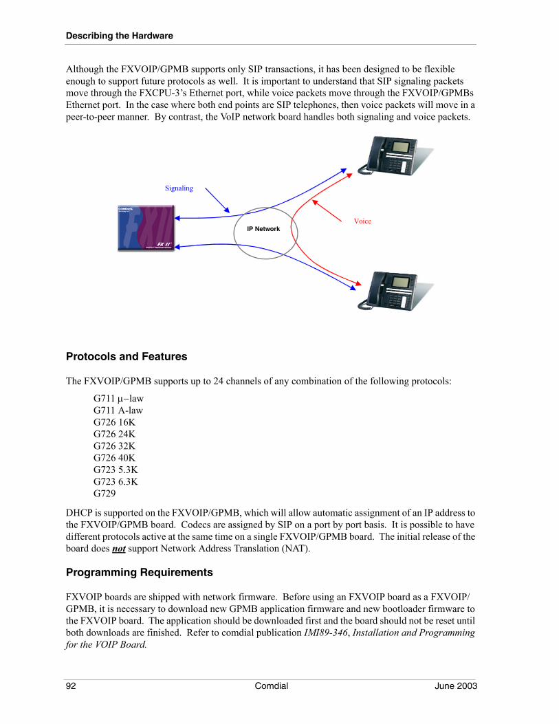
Describing the Hardware
Although the FXVOIP/GPMB supports only SIP transactions, it has been designed to be flexible enough to support future protocols as well. It is important to understand that SIP signaling packets move through the FXCPU-3’s Ethernet port, while voice packets move through the FXVOIP/GPMBs Ethernet port. In the case where both end points are SIP telephones, then voice packets will move in a peer-to-peer manner. By contrast, the VoIP network board handles both signaling and voice packets.
Protocols and Features
The FXVOIP/GPMB supports up to 24 channels of any combination of the following protocols:
G711 µ−lawG711 A-lawG726 16KG726 24KG726 32KG726 40KG723 5.3KG723 6.3KG729
DHCP is supported on the FXVOIP/GPMB, which will allow automatic assignment of an IP address to the FXVOIP/GPMB board. Codecs are assigned by SIP on a port by port basis. It is possible to have different protocols active at the same time on a single FXVOIP/GPMB board. The initial release of the board does not support Network Address Translation (NAT).
Programming Requirements
FXVOIP boards are shipped with network firmware. Before using an FXVOIP board as a FXVOIP/GPMB, it is necessary to download new GPMB application firmware and new bootloader firmware to the FXVOIP board. The application should be downloaded first and the board should not be reset until both downloads are finished. Refer to comdial publication IMI89-346, Installation and Programming for the VOIP Board.
Signaling
Voice IP Network
92 Comdial June 2003
FX Installation & Maintenance Manual - Volume 1
Because many of the protocol decisions are made by the SIP phones, the FXVOIP/GPMB board has fewer programming options than the VoIP board.
1. Board’s IP Address: The IP address of the FXVOIP/GPMB board’s Ethernet port. If DHCP is enabled, this entry is not required.
2. Network Mask. The Network Mask of the FXVOIP/GPMB Ethernet port.3. Gateway. The IP address of the gateway router.4. IP Precedence. This value assigns a priority level to voice packets. The default setting is 5.5. VAD (Voice Activity Detection). Voice Activity Detection is selectable on a board wide basis.
When activated, the board monitors transmit levels and stops sending packets when silence is detected. This feature greatly reduces packet traffic. This option will have no effect on G723 and G729 codecs, since these protocols already implement VAD. The default setting for this entry is Disabled.
6. Packet Size. This option is selectable on a board wide basis. Selecting Large results in more efficient usage of bandwidth, but will introduce some delay and slight degradation of voice qual-ity. Selecting Small will result in maximum voice quality, but will increase Ethernet traffic. The default setting for this entry is Large.
7. Diagnostic Items. All diagnostic items that are programmable for the VoIP board are also pro-grammable for the FXVOIP/GPMB board.
SIP Endpoints
The FXVOIP/GPMB supports SIP endpoints. These endpoints include the Softphone and USB telephone. The SIP signaling between the endpoints is made through the Ethernet port of the FXCPU-3, while the voice path is through the General Purpose Media Board.
SIP Endpoint Provisioning is a programming entry in Station Programming. Additionally, Email Addresses and Registration Passwords, Registration Authorization, Expiration Timer, and User Names are programmed in the Station programming screen.
• Email Address-Used for mailing voice mail messages.
• Registration Password-Used when Station Registration Authorization is not “None”.
• Registration Authorization-Set to Digest or None. The default setting is ‘None’. When set to Digest, anytime a SIP connection is attempted, authorization must be obtained before the connection is allowed.
• Expiration Timer-Sets the time that a registration is valid. When 50% of the timer value has elapsed, the endpoint is re-registered if the SIP endpoint is still connected to the LAN.
• User Name - This entry is typically the name of a person using the phone, or any alpha/numeric string that will be used as an address to identify the station for SIP calls.
Note: In addition to the FXVoIP settings, each SIP endpoint must be assigned a unique station number. Refer to Volume 3, Section 5.6.13 for instructions.
June 2003 Comdial 93
Describing the Hardware
Soft Phone
Comdial’s Soft Phone model 8904 is a Windows based software application that uses Session Initiation Protocol (SIP), and that allows you to use your PC workstation to communicate with the FX Digital System and beyond. This interface gives your PC the capability to perform as a multimedia tool for voice and video communications. For details, see the online help system supplied with the product.
8902-P IP Telephone
Comdial’s IP telephone model 8902-P connects to your network, and is designed to operate as an extension on the FX-II telephone system. Refer to Comdial publication GCA70398, Station User’s Guide, for instructions on its use.
3.1.20 DTMF RECEIVER BOARD (FXDTMF-XX)
The FX system supports the use of on-premise industry-standard telephones (IST) through IST station interface boards. When using the FXISTM-Cxx IST boards, additional DTMF receivers are not a requirement, since those boards have a DTMF receiver built-in to the board architecture. However, if you plan to use tone dial DID or E&M lines with the T1 digital carrier transmission option, you will typically need one additional DTMF receiver for every six lines. This means you will need four receivers for each FXT1 board that is configured for 24 DID or E&M lines.
The FXDTMF-16 and FXDTMF-32, provide either 16 or 32 DTMF receivers. You can install the boards in any available universal slot in the FX system. The maximum number of receivers allowed in the FX system is defined in the following table:
The software only permits installers to add the universal DTMF receiver board to the system if there is enough room to add all the DTMF receivers on the board. If the maximum is surpassed, the system will not accept the board addition and a warning dialog appears on the VMMI display.
3.1.21 DTMF RECEIVER CARD (DXOPT-TON)
The DXOPT-TON DTMF Receiver Card contains 4 built-in DTMF receivers. This card mounts as a daughter board on the FXINT-MAUXII board when the DXOPT-SYN synchronization card is not required. It can also be mounted on the FXINT-FSRV expansion board.
Platform Maximum DTMF Receivers
96 Port 93480 Port 253
94 Comdial June 2003

FX Installation & Maintenance Manual - Volume 1
This page left blank intentionally
June 2003 Comdial 95

Describing the Hardware
96 Comdial June 2003
MP5000 I&M Manual - Volume 1
INDEX
AAuxiliary board 84
BBBLFXII 83
CCentral Processor Board
FXCPU-3 80Centrex Message Waiting Line Board 88CO LIne Board 87CPU-3
Programming Requirements 81
DDID/E&M LIne Board 88Digital Station Board 87Documentation 2DTMF Receiver Board 94DTMF Receiver Card 94
EE911 88Email Address 93External Battery Assembly 83
FFCC Registration Numbers 12Feature Listing 13Fiber Optics Expansion Kits 85FXGST-08 87FXINT-MAUXII 84FXNET Board 89FXSRV2-II 83FXSRV-EX 83
IISDN-PRI Interface Line Board 89IST Station Board 90
LLED Status Indicator 86LIne Board 87Loop Limits 11
MMain/Expansion Cabinet 79Memory Upgrades
FXCPU-3 81
P
Part Numbers 9precharge jack 86Product Codes 9Programming Requirements
General Purpose Media Board 92
RRegistration Authorization 93Registration Passwords 93Ribbon Cable Expansion Kit 84Ringer Equivalence 12
SSCSI Expansion Kits 84Services Board 83Session Initiation Protocol 3, 63SIP 3Specifications 10Status Indicators 81status lights 86Synchronization Card 89System Specifications 10
TT1 Line Board 88Telephones
Features 7Supported Phones 5
UUpgrading CPU-3 Memory 81User Guides 2User Names 93
VVoIP Line Board 91
February, 04 Comdial 97

Index-98 Comdial February, 04

This manual has been developed by Comdial Corporation (the “Company”) and is intended for the use of its customers and service personnel. The information in this manual is subject to change without notice. While every effort has been made to eliminate errors, the Company disclaims liability for any difficulties arising from the interpretation of the information contained herein.
The information contained herein does not purport to cover all details or variations in equipment or to provide for every possible contingency to be met in connection with installation, operation, or mainte-nance. Should further information be desired, or should particular problems arise which are not covered sufficiently for the purchaser’s purposes, contact Comdial, Inside Sales Department, Sarasota, Florida 34232.

IMI89358.212/03Printed in U.S.A.