MERCEDES G-WAGON Ultra-Light Fire Tanker...
70
Version 3.01, 05/2017 Department of Environment, Land, Water and Planning MERCEDES G-WAGON Ultra-Light Fire Tanker Body Revision 3.01 OPERATION MANUAL
Transcript of MERCEDES G-WAGON Ultra-Light Fire Tanker...

Version 3.01, 05/2017
Department of Environment, Land, Water and Planning
MERCEDES G-WAGON
Ultra-Light Fire Tanker Body
Revision 3.01
OPERATION MANUAL

Quik Corp G-Wagon Ultra-Light Fire Tanker Body
DELWP G-Wagon Operators Manual Revision 3.01, 05/2017 Page 2
Table of Contents TABLE OF FIGURES ............................................................................................................ 4
CAUTION .............................................................................................................................. 5
TERMS AND ABBREVIATIONS ........................................................................................... 6
1 SYMBOLS ..................................................................................................................... 7
2 VEHICLE INFORMATION .............................................................................................. 8
3 APPLIANCE DESCRIPTION........................................................................................ 11
4 APPLIANCE USE ........................................................................................................ 12
5 APPLIANCE CONSTRUCTION ................................................................................... 13
5.1 Front Side ............................................................................................................. 13
5.1.1 Stowage/Lockers Closed ............................................................................... 13
5.2 Near Side .............................................................................................................. 14
5.2.1 Stowage/Lockers Closed ............................................................................... 14
5.2.2 Stowage/Lockers Open .................................................................................. 15
5.3 Off Side ................................................................................................................. 16
5.3.1 Stowage/Lockers Closed ............................................................................... 16
5.3.2 Stowage/Lockers Open .................................................................................. 17
5.4 Rear Side .............................................................................................................. 18
5.5 Stowage/Lockers Closed ...................................................................................... 18
5.5.1 Stowage/Lockers Open .................................................................................. 19
5.5.2 Pull Out Drawer ............................................................................................. 20
5.6 Pump & Plumbing Control Panels ....................................................................... 21
6 APPLIANCE OPERATING PROCEDURES ................................................................. 22
6.1 Cabin .................................................................................................................... 22
6.1.1 Control Pad .................................................................................................... 23
6.1.2 Reverse Monitor ............................................................................................ 24
6.1.3 Check Body Warning ..................................................................................... 25
6.1.4 Air Compressor .............................................................................................. 25
6.1.5 Fire Curtains .................................................................................................. 26
6.2 Engine & Pump ..................................................................................................... 27
6.2.1 Priming the Pump .......................................................................................... 27
6.2.2 Hatz Diesel Engine ........................................................................................ 28
6.2.3 Davey Pump .................................................................................................. 29
6.3 Plumbing ............................................................................................................... 29
6.3.1 Water Source ................................................................................................. 29

Quik Corp G-Wagon Ultra-Light Fire Tanker Body
DELWP G-Wagon Operators Manual Revision 3.01, 05/2017 Page 3
6.3.2 Water Delivery ............................................................................................... 31
6.3.3 Hose Reel ...................................................................................................... 32
6.3.4 Plumbing Strainers......................................................................................... 34
6.4 Water Tank ........................................................................................................... 34
6.4.1 Filling ............................................................................................................. 35
6.4.2 Draining ......................................................................................................... 37
6.5 Foam System ........................................................................................................ 38
6.5.1 Inducting the Foam ........................................................................................ 38
6.5.2 Flushing the Foam ......................................................................................... 39
6.5.3 Twist to Clean Filter ....................................................................................... 40
6.6 Ancillary Equipment .............................................................................................. 41
6.6.1 Chainsaw Drawer .......................................................................................... 41
6.6.2 Spare Wheel Carrier ...................................................................................... 44
6.6.3 Drip Torches .................................................................................................. 46
6.6.4 Jerry Can ....................................................................................................... 47
6.6.5 Layflat Hoses ................................................................................................. 48
6.6.6 Rakehoes, Shovels and Crowbar ................................................................... 49
6.6.7 Standpipe ...................................................................................................... 50
6.7 Appliance Tray – Connecting and Disconnecting .................................................. 51
6.7.1 Pump Module Removal .................................................................................. 52
6.7.2 Pump Module Refitting ................................................................................... 53
7 APPLIANCE MAINTENANCE PROCEDURES ............................................................ 54
7.1 Electrical ............................................................................................................... 54
7.1.1 Under bonnet ................................................................................................. 54
7.1.2 Cabin ............................................................................................................. 54
7.1.3 Pump module................................................................................................. 54
7.2.1 Pump Area Maintenance....................................................................................... 55
7.2.2 Maintenance schedule ................................................................................... 56
7.2.3 Removing the Rear Pump Locker .................................................................. 57
8 APPENDIX A – ELECTRICAL DIAGRAMS .................................................................. 58
9 APPENDIX A – ELECTRICAL DIAGRAMS .................................................................. 59
10 APPENDIX A – ELECTRICAL DIAGRAMS .............................................................. 60
11 APPENDIX A – ELECTRICAL DIAGRAMS .............................................................. 61
12 APPENDIX A – ELECTRICAL DIAGRAMS .............................................................. 62
13 APPENDIX A – ELECTRICAL DIAGRAMS .............................................................. 63
14 APPENDIX B – PLUMBING DIAGRAM .................................................................... 64

Quik Corp G-Wagon Ultra-Light Fire Tanker Body
DELWP G-Wagon Operators Manual Revision 3.01, 05/2017 Page 4
15 APPENDIX B – PLUMBING DIAGRAM .................................................................... 65
16 APPENDIX D – SPARE PARTS ............................................................................... 66
17 Component Warranties ............................................................................................. 67
TABLE OF FIGURES Figure 1: Front View of Vehicle - Dimensioned...................................................................... 8
Figure 2: Near/Passenger Side View of Vehicle – Dimensioned ........................................... 9
Figure 3: Off/Driver Side View of Vehicle - Dimensioned ....................................................... 9
Figure 4: Rear View of Vehicle - Dimensioned .................................................................... 10
Figure 5: Front Side View of Appliance ............................................................................... 13
Figure 6: NS View of Appliance – Labelled ......................................................................... 14
Figure 7: NS View of Appliance – Labelled – Lockers and Stowage Open .......................... 15
Figure 8: OS View of Appliance – Labelled ......................................................................... 16
Figure 9: OS View of Appliance – Labelled – Lockers and Stowage Open .......................... 17
Figure 10: Rear Side View of Appliance – Labelled ............................................................. 18
Figure 11: Rear Side View of Appliance – Labelled – Lockers and Stowage Open ............. 19
Figure 12: Pump and Plumbing Control Panels - Labelled .................................................. 21
Figure 13: Dashboard inside Vehicle Cabin ........................................................................ 21
Figure 14: Control Pad inside Vehicle Cabin ....................................................................... 23
Figure 15: Dashboard inside Vehicle Cabin ........................................................................ 24
Figure 16: Dashboard inside Vehicle Cabin ........................................................................ 25
Figure 17: Dashboard inside Vehicle Cabin ........................................................................ 26
Figure 18: Curtains inside Vehicle Cabin............................................................................. 26
Figure 19: Blankets inside Vehicle Cabin ............................................................................ 28
Figure 20: Blankets inside Vehicle Cabin ............................................................................ 28
Figure 21: Pump Panel ....................................................................................................... 27
Figure 22: External Suction Locking Storz ........................................................................... 30
Figure 23: Hose Reel Operation .......................................................................................... 32
Figure 24: Hose Reel Rewind ............................................................................................. 33
Figure 25: Water Tank Overhead Fill Point ......................................................................... 35
Figure 26: Pump Panel – Hydrant / Suction Tank Fill .......................................................... 36
Figure 27: Pump Panel – Foam Operation .......................................................................... 38
Figure 28: Pump Panel – Twist to Clean ............................................................................. 40
Figure 29: Chainsaw ........................................................................................................... 41
Figure 30: Spare Wheel ...................................................................................................... 44

Quik Corp G-Wagon Ultra-Light Fire Tanker Body
DELWP G-Wagon Operators Manual Revision 3.01, 05/2017 Page 5
CAUTION
Important notice – please read
Quik Corp Pty Ltd had used its best endeavours to ensure this material is accurate at the
time of printing. However, all information must be confirmed with your Manager or Safety
Officer, as specifications will change over time.
Some photos may vary slightly from appliance due to ongoing product improvements.
PLEASE READ AND UNDERSTAND ALL ASPECTS OF THE FIRE APPLIANCE
OPERATION AND USAGE PRIOR TO USING THE VEHICLE. FAILURE TO FOLLOW
INSTRUCTIONS, PROCEDURES, SERVICE SCHEDULES, MISUSE OR ABUSE OF
ITEMS MAY RESULT IN INJURY OR DAMAGE.
To the extent permitted by law, Quik Corp Pty Ltd or its directors or employees, will not be
liable for any damage, loss or expense incurred as a result or reliance on the information
and images contained in this manual.
Quik Corp G-Wagon Ultra-Light Fire Tanker Body
DELWP G-Wagon Operators Manual Revision 3.01, 05/2017 Page 6
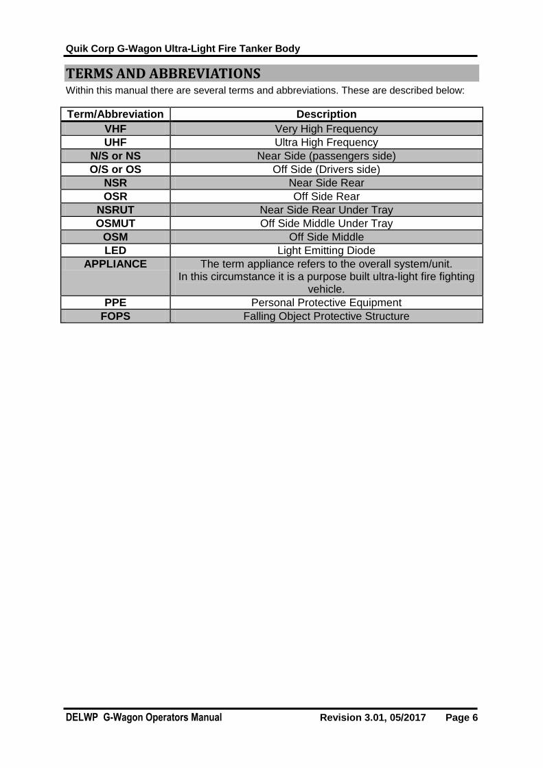
TERMS AND ABBREVIATIONS Within this manual there are several terms and abbreviations. These are described below:
Term/Abbreviation Description
VHF Very High Frequency
UHF Ultra High Frequency
N/S or NS Near Side (passengers side)
O/S or OS Off Side (Drivers side)
NSR Near Side Rear
OSR Off Side Rear
NSRUT Near Side Rear Under Tray
OSMUT Off Side Middle Under Tray
OSM Off Side Middle
LED Light Emitting Diode
APPLIANCE The term appliance refers to the overall system/unit. In this circumstance it is a purpose built ultra-light fire fighting
vehicle.
PPE Personal Protective Equipment
FOPS Falling Object Protective Structure
Quik Corp G-Wagon Ultra-Light Fire Tanker Body
DELWP G-Wagon Operators Manual Revision 3.01, 05/2017 Page 7
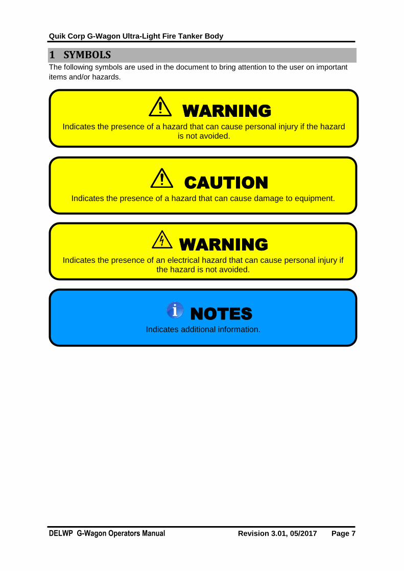
1 SYMBOLS The following symbols are used in the document to bring attention to the user on important
items and/or hazards.
WARNING
Indicates the presence of a hazard that can cause personal injury if the hazard is not avoided.
CAUTION
Indicates the presence of a hazard that can cause damage to equipment.
WARNING
Indicates the presence of an electrical hazard that can cause personal injury if the hazard is not avoided.
NOTES
Indicates additional information.
Quik Corp G-Wagon Ultra-Light Fire Tanker Body
DELWP G-Wagon Operators Manual Revision 3.01, 05/2017 Page 8
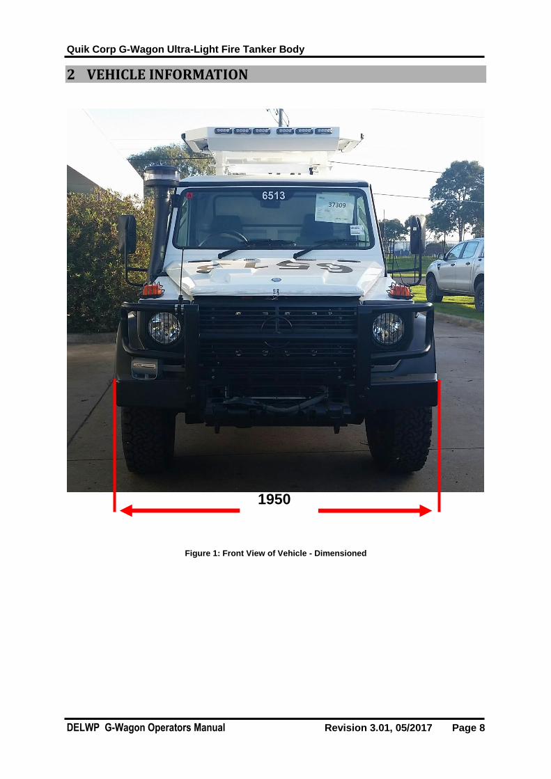
2 VEHICLE INFORMATION
Figure 1: Front View of Vehicle - Dimensioned
1950

Quik Corp G-Wagon Ultra-Light Fire Tanker Body
DELWP G-Wagon Operators Manual Revision 3.01, 05/2017 Page 9
Figure 2: Near/Passenger Side View of Vehicle – Dimensioned
Figure 3: Off/Driver Side View of Vehicle - Dimensioned
5750
3416
435
940
23
50

Quik Corp G-Wagon Ultra-Light Fire Tanker Body
DELWP G-Wagon Operators Manual Revision 3.01, 05/2017 Page 10
1950
Figure 4: Rear View of Vehicle - Dimensioned
1950
Quik Corp G-Wagon Ultra-Light Fire Tanker Body
DELWP G-Wagon Operators Manual Revision 3.01, 05/2017 Page 11
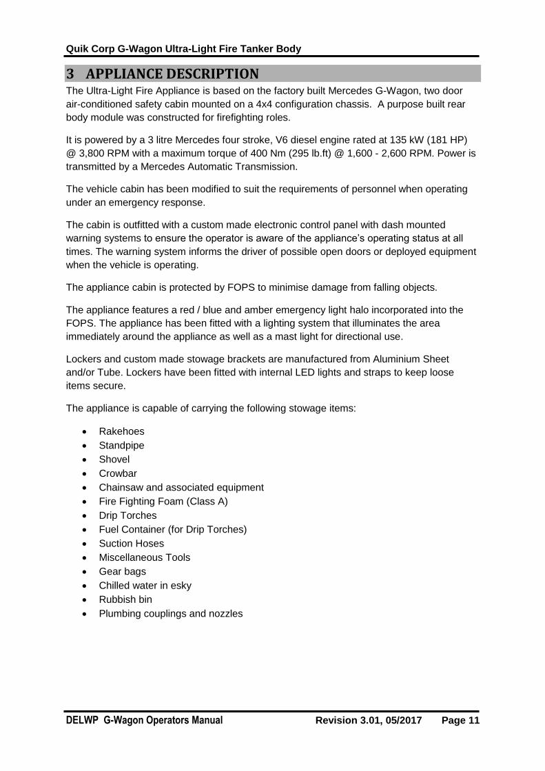
3 APPLIANCE DESCRIPTION The Ultra-Light Fire Appliance is based on the factory built Mercedes G-Wagon, two door
air-conditioned safety cabin mounted on a 4x4 configuration chassis. A purpose built rear
body module was constructed for firefighting roles.
It is powered by a 3 litre Mercedes four stroke, V6 diesel engine rated at 135 kW (181 HP)
@ 3,800 RPM with a maximum torque of 400 Nm (295 lb.ft) @ 1,600 - 2,600 RPM. Power is
transmitted by a Mercedes Automatic Transmission.
The vehicle cabin has been modified to suit the requirements of personnel when operating
under an emergency response.
The cabin is outfitted with a custom made electronic control panel with dash mounted
warning systems to ensure the operator is aware of the appliance’s operating status at all
times. The warning system informs the driver of possible open doors or deployed equipment
when the vehicle is operating.
The appliance cabin is protected by FOPS to minimise damage from falling objects.
The appliance features a red / blue and amber emergency light halo incorporated into the
FOPS. The appliance has been fitted with a lighting system that illuminates the area
immediately around the appliance as well as a mast light for directional use.
Lockers and custom made stowage brackets are manufactured from Aluminium Sheet
and/or Tube. Lockers have been fitted with internal LED lights and straps to keep loose
items secure.
The appliance is capable of carrying the following stowage items:
Rakehoes
Standpipe
Shovel
Crowbar
Chainsaw and associated equipment
Fire Fighting Foam (Class A)
Drip Torches
Fuel Container (for Drip Torches)
Suction Hoses
Miscellaneous Tools
Gear bags
Chilled water in esky
Rubbish bin
Plumbing couplings and nozzles

Quik Corp G-Wagon Ultra-Light Fire Tanker Body
DELWP G-Wagon Operators Manual Revision 3.01, 05/2017 Page 12
4 APPLIANCE USE The main uses of the Ultra-Light Fire Response vehicle are:
Transportation of two personnel and equipment to an incident on paved or unpaved
roads.
To provide a fire response for Fire Fighting
To provide scene lighting in response situations.
To provide communication tools
To provide enhanced cabin protection with FOPS and heat curtains
To transport 620L of usable water
To provide the pump with water from on-board and external sources (I.e. Pool, Dam,
Hydrant, etc.)
To add Class A foam solutions into the water delivery of the system.

Quik Corp G-Wagon Ultra-Light Fire Tanker Body
DELWP G-Wagon Operators Manual Revision 3.01, 05/2017 Page 13
5 APPLIANCE CONSTRUCTION
5.1 Front Side
5.1.1 Stowage/Lockers Closed
Figure 5: Front Side View of Appliance
Item Label Item Name
1 FOPS
2 Siren speaker
3 Emergency Lights
1 3
2

Quik Corp G-Wagon Ultra-Light Fire Tanker Body
DELWP G-Wagon Operators Manual Revision 3.01, 05/2017 Page 14
5.2 Near Side
5.2.1 Stowage/Lockers Closed
Figure 6: NS View of Appliance – Labelled
Item Label Item Name
1 FOPS
2 Signboard stowage
3 GPS aerial
4 Near Side Front Locker
5 Spare Wheel + Carrier
6 620L Water Tank
7 Near Side Rear locker
8 Pump panel light
9 Pump Plumbing Panel
10 Pump Electrical Panel
11 Near Side Rear Under Tray locker
12 Forklift points
13 Hand wash station
14 Standpipe
15 Under tray tool stowage
16 Under tray light
1 3 2 4 5 7 8
12 11 14
6 9
13 16
10
15

Quik Corp G-Wagon Ultra-Light Fire Tanker Body
DELWP G-Wagon Operators Manual Revision 3.01, 05/2017 Page 15
5.2.2 Stowage/Lockers Open
Figure 7: NS View of Appliance – Labelled – Lockers and Stowage Open
Item Label Item Name
1 Chainsaw equipment
PPE
2 Chainsaw
Fuel
Axe
Pulaski
3 Personal bags storage
4 Suction hose and strainer
2
1
4 3

Quik Corp G-Wagon Ultra-Light Fire Tanker Body
DELWP G-Wagon Operators Manual Revision 3.01, 05/2017 Page 16
5.3 Off Side
5.3.1 Stowage/Lockers Closed
Figure 8: OS View of Appliance – Labelled
Item Label Item Name
1 Light mast
2 Hose Reel
3 Off Side Rear locker
4 630L Water Tank
5 Off Side Mid Locker
6 Off Side Front Locker
7 FOPS Lights
8 Signboard stowage
9 FOPS
10 Under tray light
11 Under tray tool stowage
12 Off Side Mid Under Tray locker
13 Tray Forklift Points
14 Off Side Rear Under tray Locker
1 2 3 4 5 6 7 8
12 11 14 10 13 13
9

Quik Corp G-Wagon Ultra-Light Fire Tanker Body
DELWP G-Wagon Operators Manual Revision 3.01, 05/2017 Page 17
5.3.2 Stowage/Lockers Open
Figure 9: OS View of Appliance – Labelled – Lockers and Stowage Open
Item Label Item Name
1 Esky Storage
2 Sunscreen
First Aid Kit
Fire Kit bags
Air compressor
Air Tank
Air outlet
3 Rubbish bin
4 Wheel chocks
Chains
1 2
3 4

Quik Corp G-Wagon Ultra-Light Fire Tanker Body
DELWP G-Wagon Operators Manual Revision 3.01, 05/2017 Page 18
5.4 Rear Side
5.5 Stowage/Lockers Closed
Figure 10: Rear Side View of Appliance – Labelled
Item Label Item Name
1 Rear Pump Locker
2 Secondary Vehicle Reverse Camera
3 Mast Light
4 Hose Reel
5 Fleet Number Plate
6 Primary Vehicle Reverse Camera
7 Number plate mount
1 2 4
5 6 7
3

Quik Corp G-Wagon Ultra-Light Fire Tanker Body
DELWP G-Wagon Operators Manual Revision 3.01, 05/2017 Page 19
5.5.1 Stowage/Lockers Open
Figure 11: Rear Side View of Appliance – Labelled – Lockers and Stowage Open
Item Label Item Name
1 Layflat Hoses
2 Rear Locker Shelf Stowage
3 Class A Foam Drum
4 Drip Torches
5 Drip Torch Fuel
6 Drawer Stowage
1 2 3 4 5 6

Quik Corp G-Wagon Ultra-Light Fire Tanker Body
DELWP G-Wagon Operators Manual Revision 3.01, 05/2017 Page 20
5.5.2 Pull Out Drawer
Figure 11.1 Pull Out Drawer Item List – Labelled - Drawer Open
Item Label Item Name
1 Fitting Storz 75mm to 65mm Storz reducing adaptor
2 Fitting Storz 65 x 65 3tpi female (CFA Rnd Thread)
3 Fitting 65mm 5tpi female to 3tpi male
4 Fitting 65mm 3tpi female to 38mm Forestry
5 Hose reel remote control
6 Fitting Storz 65 x 1 1/2”BSP Fem Adaptor & Fitting forestry (Wajax) 38mm x 38mm BSP male
7 Hose reel crank
8 Nozzle Protek 360 (1”) & Fitting Forestry (Wajax) 38mm x 25mm BSP male
9 Washer Kit (Storz 75mm, Storz 65mm, Forestry WAJAX 38mm, 65mm 3tpi / 5tpi)
10 Spanner Storz 65/38
9
10
8
7
3
2
4
6
5
1

Quik Corp G-Wagon Ultra-Light Fire Tanker Body
DELWP G-Wagon Operators Manual Revision 3.01, 05/2017 Page 21
5.6 Pump & Plumbing Control Panels
Figure 12: Pump and Plumbing Control Panels - Labelled
Item Label Item Name
1 Water Level Indicator
2
Pump area light
3 Pump to Tank Ball Valve
4 Hose Reel Ball Valve – Water / Foam
5 Discharge Pressure Gauge
6 Delivery Ball Valve
7 Foam Isolation Valve
8 Dosatron Twist to Clean Filter
9 Dosatron Foam Inductor
10 Primer Isolation Valve
11 Primer
12 Pump Engine Warning Lights
13 Pump Engine Ignition / Start
14 Throttle Adjuster
15 Suction Ball Valve – External / Tank
1 2 3 4 5 6
10
8 9
11
13 14 12 15
7

Quik Corp G-Wagon Ultra-Light Fire Tanker Body
DELWP G-Wagon Operators Manual Revision 3.01, 05/2017 Page 22
6 APPLIANCE OPERATING PROCEDURES
6.1 Cabin The cabin of the appliance is a standard Mercedes G-Wagon fit out with several custom
modifications. These modifications include:
Fitment of a Reverse camera.
Warning Light for locker open / Mast raised.
Control pad for siren, emergency and general lighting controls
Air compressor control
Fire curtains
Please refer to the Mercedes G-Wagon operating manual for instructions on how to operate
the standard Mercedes systems. For the custom modifications, please refer to sections
below for operating instructions.

Quik Corp G-Wagon Ultra-Light Fire Tanker Body
DELWP G-Wagon Operators Manual Revision 3.01, 05/2017 Page 23
6.1.1 Control Pad
The control pad is used to activate all emergency controls and area lighting.
Figure 13: Control Pad inside Vehicle Cabin
Item Label Item Operation Interlock
Alert Turns on all red / blue warning lights and activate siren
Clear Turns off all functions
Wail Yelp Turns on/off siren only
Siren 2 Turns on/off siren only
Man Momentary siren operation
Primary Turns on all red / blue warning lights
AMB S Turns on amber steady burn warning lights
AMB F Turns on amber flashing warning lights
Tray Turns on under tray area lights Park brake must be on
Mast Turns on mast light
Radio Not Used
Light Not Used
Alt Not Used
CAUTION
Ensure that Mast light is off and properly stowed before transit on road. Mast is only to be left raised when off road at walking speed.

Quik Corp G-Wagon Ultra-Light Fire Tanker Body
DELWP G-Wagon Operators Manual Revision 3.01, 05/2017 Page 24
6.1.2 Reverse Monitor
Figure 14: Dashboard inside Vehicle Cabin
Item Label Item Name
1 Manual activation of camera
2 Manual selection between cameras
The monitor can also be turned on manually by pressing the top right button and then
pressing the bottom button, S to switch between camera displays.
Please refer to the OEM operating manual for complete operating instructions for this
product.
1
2

Quik Corp G-Wagon Ultra-Light Fire Tanker Body
DELWP G-Wagon Operators Manual Revision 3.01, 05/2017 Page 25
6.1.3 Check Body Warning
The warning light will illuminate if any locker door is opened or if the light mast is unhoused
or if the spare wheel is unhoused. An audible warning will also sound if a locker is opened
or the spare wheel is unhoused and park brake is released. Audible warning does not
activate for mast raised.
Figure 15: Dashboard inside Vehicle Cabin
Item Label Item Name
1 Check Body Warning
2 Air compressor switch
6.1.4 Air Compressor
The compressor switch enables the air compressor when vehicle ignition is on. The air
compressor is pressure regulated and will turn itself off when the air tank reaches max
pressure.
Ensure vehicle running and air compressor switch on prior to connecting tyre inflation hose.
The Tyre inflation hose incorporates a pull to release coupling
1 2
Quik Corp G-Wagon Ultra-Light Fire Tanker Body
DELWP G-Wagon Operators Manual Revision 3.01, 05/2017 Page 26
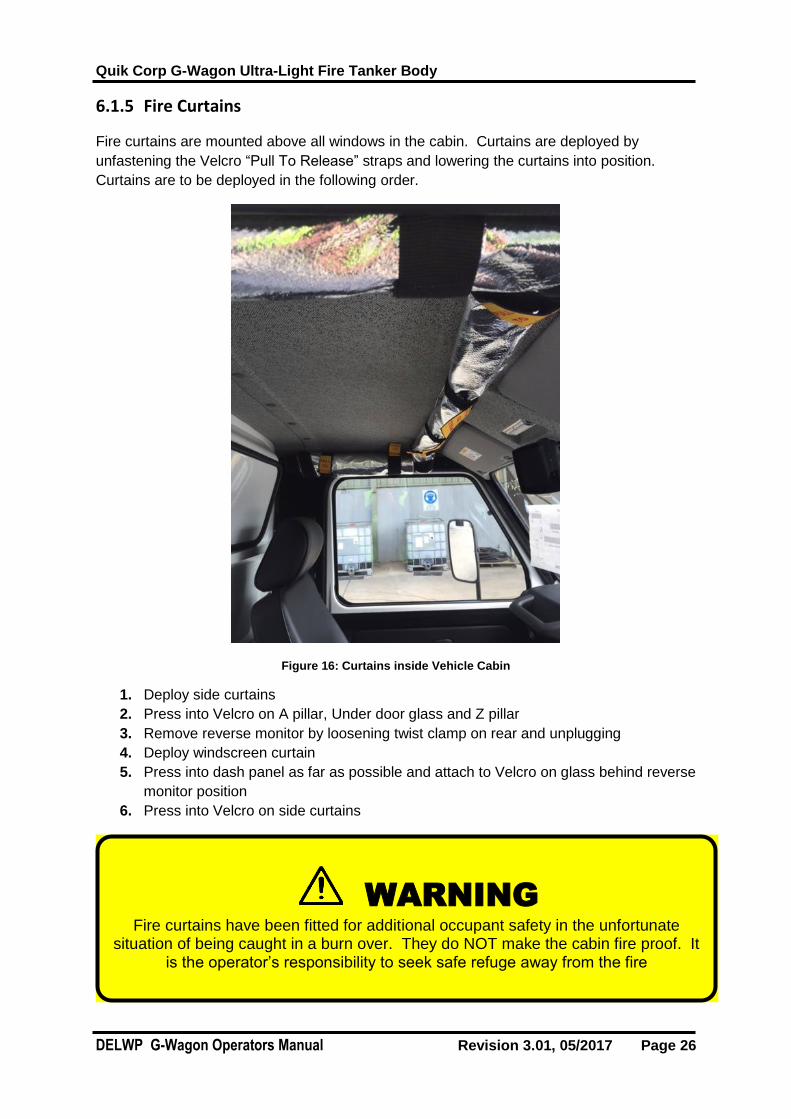
6.1.5 Fire Curtains
Fire curtains are mounted above all windows in the cabin. Curtains are deployed by
unfastening the Velcro “Pull To Release” straps and lowering the curtains into position.
Curtains are to be deployed in the following order.
Figure 16: Curtains inside Vehicle Cabin
1. Deploy side curtains
2. Press into Velcro on A pillar, Under door glass and Z pillar
3. Remove reverse monitor by loosening twist clamp on rear and unplugging
4. Deploy windscreen curtain
5. Press into dash panel as far as possible and attach to Velcro on glass behind reverse
monitor position
6. Press into Velcro on side curtains
WARNING
Fire curtains have been fitted for additional occupant safety in the unfortunate situation of being caught in a burn over. They do NOT make the cabin fire proof. It
is the operator’s responsibility to seek safe refuge away from the fire

Quik Corp G-Wagon Ultra-Light Fire Tanker Body
DELWP G-Wagon Operators Manual Revision 3.01, 05/2017 Page 27
6.2 Engine & Pump
6.2.1 Priming the Pump
This appliance is fitted with a manual primer to the right of the pump panel and is protected
with an isolation valve. The primer will be required when drafting or at times when water
isn’t present in the pump.
Figure 17: Pump Panel
Item Label Item Name
1 Pump Engine Controls
2 Discharge Valves
3 Suction Valve
4 Primer Isolation Valve
5 Primer
6 Throttle
To prime the pump;
1. With pump engine turned OFF
2. Ensure that all discharge valves are in the closed position.
3. Ensure suction valve open to tank or external supply
4. Open primer isolation valve
5. Pump primer handle until water streams out of the primer outlet under the deck
6. Close primer isolation valve
7. Start pump engine
3
4
5
1
2
6
Quik Corp G-Wagon Ultra-Light Fire Tanker Body
DELWP G-Wagon Operators Manual Revision 3.01, 05/2017 Page 28
6.2.2 Hatz Diesel Engine
The diesel engine is an air-cooled motor which relies on flowing air to cool it. Ensure cover is
removed prior to starting.
Please refer to OEM instructions for operating and servicing requirements.
Starting the Engine
The starting procedure for the engine is as follows:
1. Ensure that all discharge valves are in the closed position.
2. Ensure suction valve open to tank or external supply
3. Prime the pump and close isolation valve
4. Pull throttle cable approx. 20mm out from off postion
5. Turn on the pump ignition switch
6. Turn ignition switch to start position. The engine will begin to crank over. If the
engine doesn’t immediately start, it may be required to adjust the throttle (Wait 2
mins between each start attempt.).
7. Adjust the throttle to provide a desired discharge pressure.
Stopping the Engine
To stop the engine, the following procedure must be followed:
1. Reduce throttle until engine shuts down
2. Once the engine has stopped, turn off the ignition switch
CAUTION
Damage to the primer will occur if the isolation valve is open and pump engine started
CAUTION
Do not cover the engine as covering the engine can cause the engine to overheat which may lead to equipment damage.
Do not crank the engine for more than 20 seconds at a time. Failure to do so may cause the starter motor to overheat/be damaged.
Ensure primer isolation valve is closed before starting pump

Quik Corp G-Wagon Ultra-Light Fire Tanker Body
DELWP G-Wagon Operators Manual Revision 3.01, 05/2017 Page 29
6.2.3 Davey Pump
The Davey pump is connect via direct drive to the engine. Please refer to the OEM
instructions for operating and servicing requirements.
The Davey pump is operated when the engine is running. The rate and pressure at which it
pumps is directly proportional to the engine speed of the Hatz engine.
The discharge pressure of the pump can be monitored on via the gauge on the plumbing
control panel
6.3 Plumbing
6.3.1 Water Source
There are effectively 3 sources of water which can be directly put into the pump on this
appliance. These are:
1. Water Tank
2. External Fire Hydrant
3. External Body of Water (such as a pool, dam, river, etc…)
External Fire Hydrant and External Body of Water are both accessed via the External
position on the Suction valve.

Quik Corp G-Wagon Ultra-Light Fire Tanker Body
DELWP G-Wagon Operators Manual Revision 3.01, 05/2017 Page 30
6.3.1.1 Water Tank To utilise water from the on-board water tank;
1. The “SUCTION” ball valve must be set to the “TANK” position.
2. Prime pump if necessary
3. Start pump
6.3.1.2 External Fire Hydrant To utilise water from the fire hydrant;
1. The “SUCTION” ball valve must be set to the EXTERNAL” position.
2. Using lay flat hose, connect the fire hydrant to the appliance via the locking Storz
coupling located in the NSRUT locker.
3. Open hydrant supply via the standpipe
4. Start pump
Figure 18: External Suction Locking Storz
Item Label Item Name
1 Locking storz
2 Filter
NOTES
While connected to the hydrant, it is possible to use excess water to fill the on board tank via the “PUMP TO TANK” valve.
1 2

Quik Corp G-Wagon Ultra-Light Fire Tanker Body
DELWP G-Wagon Operators Manual Revision 3.01, 05/2017 Page 31
6.3.1.3 External Body of Water To utilise water from a dam or pool;
1. The “SUCTION” ball valve must be set to the “EXTERNAL” position.
2. Ensure the on board ridged hose is connected to the appliance via the locking Storz
coupling located in the NSRUT locker and filter fitted to the other end of the ridged
hose.
3. Drop the filtered end of the hose into water supply.
4. Prime pump
5. Start pump
6.3.2 Water Delivery
Water delivery is available via the hose reel and a delivery valve located on the pump panel.
The delivery on the pump panel incorporates a 38mm forestry coupling. A ball valve is also
located before this fitting to control the discharge of water.
NOTES
While connected to the hydrant, it is possible to use excess water to fill the on board tank via the “PUMP TO TANK” valve.
CAUTION
Ensure the cap is on the discharge point when not in use to protect the fitting from damage and wear.
A 2mm vent hole is included to ensure cap is never under pressure.

Quik Corp G-Wagon Ultra-Light Fire Tanker Body
DELWP G-Wagon Operators Manual Revision 3.01, 05/2017 Page 32
6.3.3 Hose Reel
There is one Quik Corp RFR4 hose reel fitted to the OS at the rear of the Pump Module. The
reel is fitted with 50 metres of 19mm flame resistant hose. The hose is fitted with a ball
clamp warning that the end of the hose is close when retracting the reel and a valve to
isolate discharge when changing nozzles.
Figure 19: Hose Reel Operation
Item Label Item Name
1 Hose Reel Lock
2 Hose Valve
6.3.3.1 To operate the hose reel: 1. Ensure the manual brake is released (turn counter clockwise).
2. Connect nozzle to the end of the hose
3. Turn the pump on
4. While holding the hose reel nozzle, open the hose reel ball valve to either Water or
Foam.
5. Pull on the hose to un-reel.
6. When in position, turn on the hose valve at the nozzle
CAUTION
Ensure the hose reel brake is released before unwinding / rewinding the hose and applied prior to transit. Failure to do so may cause damage to the brake
mechanism / hose fittings.
1
2
Quik Corp G-Wagon Ultra-Light Fire Tanker Body
DELWP G-Wagon Operators Manual Revision 3.01, 05/2017 Page 33
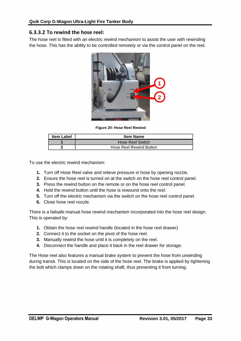
6.3.3.2 To rewind the hose reel: The hose reel is fitted with an electric rewind mechanism to assist the user with rewinding
the hose. This has the ability to be controlled remotely or via the control panel on the reel.
Figure 20: Hose Reel Rewind
Item Label Item Name
1 Hose Reel Switch
2 Hose Reel Rewind Button
To use the electric rewind mechanism:
1. Turn off Hose Reel valve and relieve pressure in hose by opening nozzle.
2. Ensure the hose reel is turned on at the switch on the hose reel control panel.
3. Press the rewind button on the remote or on the hose reel control panel.
4. Hold the rewind button until the hose is rewound onto the reel.
5. Turn off the electric mechanism via the switch on the hose reel control panel.
6. Close hose reel nozzle.
There is a failsafe manual hose rewind mechanism incorporated into the hose reel design.
This is operated by:
1. Obtain the hose reel rewind handle (located in the hose reel drawer)
2. Connect it to the socket on the pivot of the hose reel.
3. Manually rewind the hose until it is completely on the reel.
4. Disconnect the handle and place it back in the reel drawer for storage.
The Hose reel also features a manual brake system to prevent the hose from unwinding
during transit. This is located on the side of the hose reel. The brake is applied by tightening
the bolt which clamps down on the rotating shaft, thus preventing it from turning.
1
2

Quik Corp G-Wagon Ultra-Light Fire Tanker Body
DELWP G-Wagon Operators Manual Revision 3.01, 05/2017 Page 34
6.3.4 Plumbing Strainers
There are strainers fitted to this appliance to protect from debris entering the pump. They are
located:
1. Internal cone strainer - In the external suction line’s locking Storz coupling located in
the NSRUT locker
2. Wye strainer - At the pump, protecting the primer line
3. Basket strainer - In the overhead tank fill
4. Suction strainer – Attached to the main suction hose
6.4 Water Tank The water tank supplied on the fire appliance is a custom made rotomolded tank with a
useable capacity of approximately 620 Litres. The tank is fitted with baffle bones to minimize
the effect of water surge.
When filling or drawing water from the tank, you will be able to monitor the amount of water
volume via a water level sight tube which is located on the NS of the pump module. The
sight tubes incorporate a fluoro float to aid in viewing water level.
The water tank also incorporates an internal overflow system and a pressure relief valve,
which will reduce the risk of damage to the tank in the case of overfilling or pressurisation of
the tank when filling whilst minimising spillage when driving.
NOTES
The Hose reel is designed to self-lay the hose on the reel when hose is rewound at up to 45 degrees off center of the fair lead roller. If hose overlaps
when rewinding, the hose should be pulled back out one layer past the overlap and rewound again.
NOTES
It is up to the operator to ensure strainers are kept clean and in good condition.
CAUTION
When filling the tank under pressure, it is up to the operator to ensure the tank fill is turned off as soon as water starts to discharge. Failure to do so could
cause damage to the tank.
Quik Corp G-Wagon Ultra-Light Fire Tanker Body
DELWP G-Wagon Operators Manual Revision 3.01, 05/2017 Page 35
6.4.1 Filling
There are 3 methods that can be utilised to fill the tank. These are detailed below.
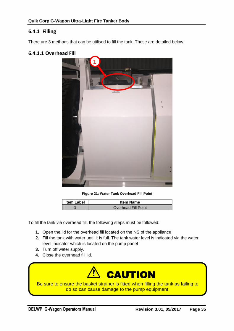
6.4.1.1 Overhead Fill
Figure 21: Water Tank Overhead Fill Point
Item Label Item Name
1 Overhead Fill Point
To fill the tank via overhead fill, the following steps must be followed:
1. Open the lid for the overhead fill located on the NS of the appliance
2. Fill the tank with water until it is full. The tank water level is indicated via the water
level indicator which is located on the pump panel
3. Turn off water supply.
4. Close the overhead fill lid.
CAUTION
Be sure to ensure the basket strainer is fitted when filling the tank as failing to do so can cause damage to the pump equipment.
1

Quik Corp G-Wagon Ultra-Light Fire Tanker Body
DELWP G-Wagon Operators Manual Revision 3.01, 05/2017 Page 36
6.4.1.2 Hydrant Fill The vehicle is fitted with a standpipe to fill the vehicle via hydrant means.
Figure 22: Pump Panel – Hydrant / Suction Tank Fill
Item Label Item Name
1 Suction Ball Valve
2 Suction External Storz Fitting
3 Water level display
To do this, conduct the following steps:
1. Remove the standpipe from its stowed position
2. Connect the standpipe to a hydrant point.
3. Connect hoses from the standpipe to the Suction External Storz fitting in the NSRUT
locker
4. Turn the standpipe valve to the open position.
5. Turn the Suction valve to External
6. Open the Pump to Tank valve
7. Close valves in reverse order as soon as water dumps out of the overflow
1
2
3

Quik Corp G-Wagon Ultra-Light Fire Tanker Body
DELWP G-Wagon Operators Manual Revision 3.01, 05/2017 Page 37
6.4.1.3 Suction Intake The suction intake system of the water pump can be used to fill the tank or be directly
channelled to the hose reel/discharge lines. To fill the tank via suction intake by the fastest
possible means, the following steps must be taken:
1. Connect the suction hose lines to the Suction External Storz fitting in the NSRUT
locker
2. Connect the Suction strainer to the end of the suction hose
3. Place suction hose in the external source of water (be sure to have the end of the
hose in the deepest section of the water source to avoid sucking air.
4. Turn the Suction valve to External
5. Prime the pump and isolate primer valve
6. Start the pump engine
7. Open the Pump to Tank valve.
8. Once the water level indicator reads full or water starts overflowing, close the Pump
to Tank valve.
6.4.2 Draining
The tank can be drained by either running the pump, discharging water from a delivery or by
removing the tank bung located in the tank sump.
CAUTION
Be sure to fit a filter/strainer to the end of the suction hose when filling the tank. Failing to do so can cause damage to the pump equipment.
CAUTION
Do not operate pump with no water in the tank. Failing to do so can cause damage to the pump equipment.

Quik Corp G-Wagon Ultra-Light Fire Tanker Body
DELWP G-Wagon Operators Manual Revision 3.01, 05/2017 Page 38
6.5 Foam System The appliance is equipped with a Dosatron foam induction system, Twist to Clean filter and
20lts of liquid foam. The foam system only supplies the hose reel. Please refer to the OEM
operating manual for detailed operating instructions and maintenance procedures for this
product.
Figure 23: Pump Panel – Foam Operation
Item Label Item Name
1 Hose reel Valve
2 Dosatron % setting
3 Foam Isolation Valve
6.5.1 Inducting the Foam
To initiate the foam system, please follow the following procedures:
1. Prime and start pump engine, running pump at max 600kPa
2. Set required foam % on dosatron
3. Turn Hose Reel valve to Foam
4. Ensure foam isolation valve (3) is open
5. Open hose reel nozzle
6. Adjust foam % as required
1
2
3

Quik Corp G-Wagon Ultra-Light Fire Tanker Body
DELWP G-Wagon Operators Manual Revision 3.01, 05/2017 Page 39
6.5.2 Flushing the Foam
To flush the foam system, please follow the following procedures:
1. Ensure that there is still a small amount of water supply left available.
2. Turn Hose Reel valve to Water
3. Open hose reel nozzle until clear water flows
4. Close Hose Reel valve
CAUTION
Do not exceed 600kPa when running foam
CAUTION
Failure to flush foam can cause premature damage to equipment

Quik Corp G-Wagon Ultra-Light Fire Tanker Body
DELWP G-Wagon Operators Manual Revision 3.01, 05/2017 Page 40
6.5.3 Twist to Clean Filter
Figure 24: Pump Panel – Twist to Clean
Item Label Item Name
1 Twist to Clean FIlter
To clean the filter, the following procedure must be used:
1. Ensure Pump is primed and running at idle speed
2. Lift red tab on lid and turn top clockwise
3. Water and debris will exit the bottom of the filter
4. Turn top and reseat red tab after cleaned
CAUTION
Ensure filter is only cleaned with pump running at idle speed.
1

Quik Corp G-Wagon Ultra-Light Fire Tanker Body
DELWP G-Wagon Operators Manual Revision 3.01, 05/2017 Page 41
6.6 Ancillary Equipment
6.6.1 Chainsaw Drawer The chainsaw and chainsaw accessories are located in the NS front locker. The chainsaw
drawer features Accuride Lock-In/Lock-Out slides.
Figure 25: Chainsaw
Item Label Item Name
1 Drawer Release
To open the drawer:
1. Push the yellow tab down and pull the drawer outwards. (do not use yellow tab as a
handle)
2. Pull the drawer outwards until it hits the limit stops and locks in the open position.
The slides will ‘click’ to indicate the locking mechanism has engaged in the open
position.
To remove the chainsaw from the drawer, undo the cutting blade clamp and the yellow strap.
This yellow strap holds the chainsaw fuel jerry can in place.
1

Quik Corp G-Wagon Ultra-Light Fire Tanker Body
DELWP G-Wagon Operators Manual Revision 3.01, 05/2017 Page 42
The chainsaw drawer is fitted with a brace to assist when sharpening the chainsaw chain.
When the drawer is fully extended, reach underneath the chainsaw drawer and pull down the
brace. The brace should lock down firmly against the through locker frame when in use.

Quik Corp G-Wagon Ultra-Light Fire Tanker Body
DELWP G-Wagon Operators Manual Revision 3.01, 05/2017 Page 43
When the chainsaw drawer is to be returned, push up the chainsaw drawer brace to secure
it inside the clamps under the drawer first, the drawer can now slide back inside the locker.

Quik Corp G-Wagon Ultra-Light Fire Tanker Body
DELWP G-Wagon Operators Manual Revision 3.01, 05/2017 Page 44
6.6.2 Spare Wheel Carrier The appliance can be fitted with one spare wheel and OSM locker OR two spare wheel
carriers.
The spare wheel carriers are electrically operated via toggle switches in the NSF and OSF
locker which operate their respective side carriers.
Figure 26: Spare Wheel
Item Label Item Name
1 Locking Pin
2 Toggle Switch
Removing the Spare Wheel:
1. Ensure vehicle ignition is on.
2. Release the locking pin for the spare wheel carrier (located on the front face of the
arm) and ensure the wheel swings free of the body.
3. Press and hold the respective toggle switch down to lower the spare wheel. Hold the
toggle switch until the wheel has lowered enough so that it is approximately 10mm off
the ground.
4. Undo the nuts holding the spare wheel on the frame.
5. Remove the spare wheel.
6. Refer to Mercedes G-Wagon user manual for instructions on replace wheels on the
vehicle.
2
1

Quik Corp G-Wagon Ultra-Light Fire Tanker Body
DELWP G-Wagon Operators Manual Revision 3.01, 05/2017 Page 45
Stowing the Spare Wheel:
1. Ensure vehicle ignition is on.
2. Place the wheel onto the frame and locate using the wheel nut holes on the wheel.
3. Secure wheel by tightening nuts.
4. Once wheel is secured on the frame, press and hold the toggle switch up to raise the
spare wheel. Hold the toggle switch until the wheel has raised enough so that it is
linear actuator has completely compressed. A limit switch on the actuator will
automatically do this. Cease pressing the toggle switch when this occurs.
5. Engage the locking pin for the spare wheel carrier (located on the front face of the
arm).
6. Push the spare wheel inwards so that the locking pin engages tightly on the ratchet
rack.
CAUTION
When lowering the wheel, ensure that the spare wheel stops approximately 10mm off the ground. Failure to do so may cause the lifting mechanism to push against the ground and cause damage to the equipment.
Ensure the locking pin for the wheel carrier is unlocked prior to lowering the wheel. Failure to do so will cause the wheel to catch on the lifting frame which can cause damage to the equipment.
WARNING
Do not stand on or hold onto the lifting mechanism at any time as it may result in user injury or damage to the mechanism.
Do not hold the spare wheel carrier during lifting or lowering operation as the swinging of the arm can cause injury and creates a pinch point.
CAUTION
Ensure the locking pin is in the down position upon stowing wheel. Failure to do so will enable the spare wheel to swing during transit which may cause damage
to equipment and bystanders.

Quik Corp G-Wagon Ultra-Light Fire Tanker Body
DELWP G-Wagon Operators Manual Revision 3.01, 05/2017 Page 46
6.6.3 Drip Torches The drip torches are located in the rear locker.
Figure 27: Rear Locker – Drip Torch
Item Label Item Name
1 QTY 2 Drip Torches
To un-stow the drip torches:
1. Open the locker door
2. Pick up the drip torch by the grab handle, lift and pull the torch outwards to remove
from storage. Note that only one drip torch can be removed at a time.
To store the torches, the reverse of the above procedures should be followed.
1

Quik Corp G-Wagon Ultra-Light Fire Tanker Body
DELWP G-Wagon Operators Manual Revision 3.01, 05/2017 Page 47
6.6.4 Jerry Can The fuel jerry can is located in the rear locker.
Figure 28: Rear Locker – Jerry Can
Item Label Item Name
1 Jerry Can - Drip Torch Fuel
To un-stow the jerry can:
1. Open the locker door
2. Unclip the fluoro securing strap via the plastic buckle.
3. Pick up the drip jerry can by the grab handle, lift and pull the can outwards to remove
from storage.
To store the jerry cans, the reverse of the above procedures should be followed.
1
Quik Corp G-Wagon Ultra-Light Fire Tanker Body
DELWP G-Wagon Operators Manual Revision 3.01, 05/2017 Page 48
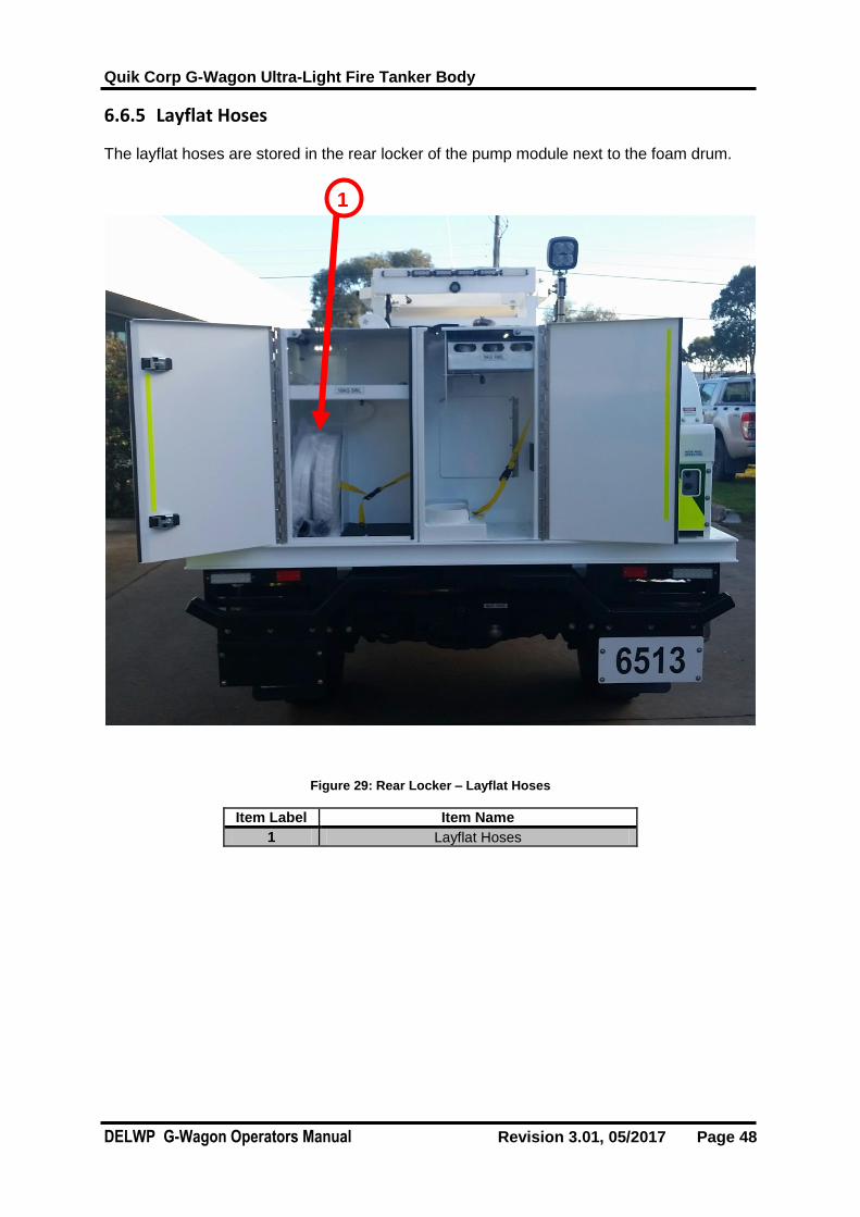
6.6.5 Layflat Hoses
The layflat hoses are stored in the rear locker of the pump module next to the foam drum.
Figure 29: Rear Locker – Layflat Hoses
Item Label Item Name
1 Layflat Hoses
1

Quik Corp G-Wagon Ultra-Light Fire Tanker Body
DELWP G-Wagon Operators Manual Revision 3.01, 05/2017 Page 49
6.6.6 Rakehoes, Shovels and Crowbar
There is stowage for two rakehoes, two shovels, one crowbar and one standpipe under the body of the appliance.
Figure 30: Under Body Stowage
Item Label Item Name
1 Shovel
2 Crowbar
3 Rakehoe
4 Standpipe
To un-stow the rakehoes:
1. Pull out the locking R-clips.
2. Slide out the rakehoes from storage.
To store the rakehoes, the reverse of the above procedures should be followed.
To unstow the shovels:
1. Push the sprung bracket away from shovel
2. Slide out the shovel from storage.
To store the shovel, the reverse of the above procedures should be followed.
To un-stow the crowbar:
1. Lift crowbar above retainer
2. Slide out the crowbar from storage.
To store the crowbar, the reverse of the above procedures should be followed.
1 2 3 4

Quik Corp G-Wagon Ultra-Light Fire Tanker Body
DELWP G-Wagon Operators Manual Revision 3.01, 05/2017 Page 50
6.6.7 Standpipe
There is one standpipe located on the NS of the appliance beneath the tray. See Figure 34.
To remove the standpipe from storage:
1. Pull out the R-clip locking pin.
2. Pull the standpipe outwards (it will slide along the frame).
3. When the stand pipe is almost out, use two hands to pick it up and remove it from the
bracket.
To store the standpipe, the reverse of the above procedures should be followed.
WARNING
Ensure all items are securely stowed before driving
WARNING
Ensure standpipe is securely stowed before driving

Quik Corp G-Wagon Ultra-Light Fire Tanker Body
DELWP G-Wagon Operators Manual Revision 3.01, 05/2017 Page 51
6.7 Appliance Tray – Connecting and Disconnecting The appliance pump module has been uniquely designed to enable fast and easy removal
with a forklift.
Figure 31: Pump Module
Item Label Item Name
1 Forklift Points
2 Locking Storz
3 Quik Latch
4 Fuel Connections
5 Electrical Connections
1
2
3
4
5

Quik Corp G-Wagon Ultra-Light Fire Tanker Body
DELWP G-Wagon Operators Manual Revision 3.01, 05/2017 Page 52
6.7.1 Pump Module Removal
1. Ensure the tank is empty of water.
2. Ensure all pump module lockers are emptied and closed.
3. Disconnect 2” suction hose from locking storz in the NSRUT locker
4. Ensure the appliance is parked on a flat hard surface with a 20m radius of clear
space that is suitable for heavy vehicles.
5. Ensure the handbrake of the vehicle is on and the vehicle engine is off.
6. Ensure personnel are absent from the cabin of the appliance.
7. Disconnect the two electrical cables linking the tray to the vehicle. These are located
under the rear drivers side of the pump module
8. Disconnect the two fuel lines between the chassis and pump module. These are
located centrally under the rear of the pump module
9. Once electrical cables and fuel lines are disconnected, unlock the tray Quik release
latches. There are four of these located under tray with 2 on each side of the vehicle.
To unlock the latch, push in and rotate the latching bar outwards. Each quick release
latch is appropriately labelled indicating the direction to unlock.
10. Once the tray is unlatched, it can be removed. Using a forklift that is sufficiently rated,
(1 ton minimal at 2m reach) lift the tray off the vehicle. Use the dedicated forklift
points located along the combing rail on each side of the tray. It is recommended that
a dogman is used for this operation to assist the forklift operator.
11. Once removed, lower carefully ensuring fuel and electrical connections do not get
caught under the tray.
12. The vinyl cover should be placed over the pump engine for protection.
CAUTION
Ensure a suitable forklift is used to lift off the tray. Failure to do so may cause the fork lift to lose balance, thus dropping and damaging the tray of the
appliance.
WARNING
Do not stand underneath or hold the tray during tray removal. Failure to do so may result in injury or death.
Stand clear of the forklift and tray during removal of the tray from the appliance. Failure to do so may result in injury or death.

Quik Corp G-Wagon Ultra-Light Fire Tanker Body
DELWP G-Wagon Operators Manual Revision 3.01, 05/2017 Page 53
6.7.2 Pump Module Refitting
1. Ensure the tank is empty of water.
2. Ensure all pump module lockers are emptied and closed.
3. Ensure the vehicle is parked on a flat hard surface with a 20m radius of clear space
that is suitable for heavy vehicles.
4. Ensure the handbrake of the vehicle is on and the vehicle engine is off.
5. Ensure personnel are absent from the cabin of the appliance.
6. Ensure personnel are wearing correct PPE such as hard hats and high visibility
vests.
7. Remove vinyl pump engine cover
8. Using a forklift that is sufficiently rated, (1 ton minimal at 2m reach) lift the tray onto
the vehicle. Use the dedicated forklift points located along the combing rail on each
side of the tray. It is recommended that a dogman is used for this operation to assist
the forklift operator.
9. Locate the pump module square to the chassis above the locating pins on the Quik
release latches then lower gently onto the chassis ensuring the electrical and fuel
lines to not get caught on componentry.
10. Once the tray is loaded, it can be secured. Lock the tray quick release latches. There
are four of these located under tray with 2 on each side of the vehicle. To lock the
latch, rotate the latch pin inwards. Each quick release latch is appropriately labelled
indicating the direction to lock.
11. Reconnect the two electrical cables linking the tray to the vehicle. These are located
under the rear drivers side of the pump module
12. Reconnect the two fuel lines between the chassis and pump module. These are
located centrally under the rear of the pump module
13. The tray is now secured and ready for operation on the vehicle.
CAUTION
Ensure a suitable forklift is used to lift on the tray. Failure to do so may cause the crane or lifting device to fail which will damage the tray of the appliance.
WARNING
Do not stand underneath or hold the tray during tray loading. Failure to do so may result in injury or death.
Stand clear of the tray and forklift during application of the tray to the appliance. Failure to do so may result in injury or death.
Quik Corp G-Wagon Ultra-Light Fire Tanker Body
DELWP G-Wagon Operators Manual Revision 3.01, 05/2017 Page 54
7 APPLIANCE MAINTENANCE PROCEDURES
7.1 Electrical Electrical control and protection circuits are located in three positions.
1. Under bonnet
2. In cabin
3. In pump module
7.1.1 Under bonnet
Two circuit breakers are located on the passenger’s side of the engine bay. These protect
the main supply to the cabin and body and can be manually isolated by pressing in the red
button on top which will release a pop out lever isolating the circuit
To reset push the pop out lever back in.
These circuit breakers should be isolated when undertaking repairs or when storing the
vehicle for extended periods
7.1.2 Cabin
The cabin electrical module is located on the rear wall of the cabin and is accessed by
removing four butterfly nuts. This module contains the siren driver which also controls area
and emergency lighting, Main fuses, Relays and radio bases.
7.1.3 Pump module
The pump module is located at the pump panel and includes fuses for fuel pump and pump
area lighting which is controlled by the pump ignition relay.

Quik Corp G-Wagon Ultra-Light Fire Tanker Body
DELWP G-Wagon Operators Manual Revision 3.01, 05/2017 Page 55
7.2.1 Pump Area Maintenance
Through normal use, the area around the pump unit can sometimes collect debris. A
provision has been made to allow easy cleaning of the area. It is recommended that the
pump area is cleaned after each use to prevent a build up.
This provision is located at the bottom of the pump panel (1). To clean the pump panel area,
a hose and/or brush can be used to wash out any debris or dirt that may be present.
1

Quik Corp G-Wagon Ultra-Light Fire Tanker Body
DELWP G-Wagon Operators Manual Revision 3.01, 05/2017 Page 56
7.2.2 Maintenance schedule
Preventative Maintenance Schedules - Vehicle Checklist FLEET NUMBER:____________________
VEHICLE CHECKLIST YEAR:_________________
Hatz Diesel Engine 1B40
Check Interval
Every
Use
1
Month
6
Months
12
Months
24
Months
Check Engine Oil Level *
Replace Engine Oil *
Check / Clean Air Cleaner * Check / Drain Water Separator (If
Equipped) *
Check and Adjust Valve Clearances *
Clean Fuel Filter *
Replace Oil Filter *
Hose Reel RFR-4
Check Interval
Every
Use
1
Month
6
Months
12
Months
24
Months
Adjust Drive Belt *
Adjust Drive Chain *
Lubricate Drive Chain *
Check Self-Guide Follower *
Check / Replace Motor Bushes *
Dosatron Proportioner D3 R2
Check Interval
Every
Use
1
Month
6
Months
12
Months
24
Months
Clean and Refit the Suction Valve *
Check Suction Valve O-Ring *
Replace Suction Valve O-Ring *
Replace Injection Cylinder Seals *
Check / Replace Suction Valve Seal *
Check / Replace Suction Tube *
Refer to OEM Manuals, vehicle operators manual or portal for additional information.
Work completed by:__________________________________
Date work completed:______________________
Quik Corp G-Wagon Ultra-Light Fire Tanker Body
DELWP G-Wagon Operators Manual Revision 3.01, 05/2017 Page 57
7.2.3 Removing the Rear Pump Locker
To access the pump for maintenance, the rear storage locker is required to be removed.
1. Remove stowage items from locker
2. Disconnect the foam hose from the Dosatron.
3. Disconnect electrical plug at rear of locker.
4. Engine pull start cord (Right hand side of locker) needs to be disconnected before
removing locker
5. Undo the six bolts securing the locker (located either side of the locker).
6. Using a mechanical lifting device or multiple people, remove the locker.
7. The pump and engine is now accessible for maintenance.
WARNING
Ensure that the engine is cool and water lines have all internal pressure release before attempting any maintenance tasks. Failing to do so may lead to personal injury.
Ensure that correct lifting techniques and/or are used when lifting the rear locker off the tray for maintenance. Failure to do so may lead to user injury.
Quik Corp G-Wagon Ultra-Light Fire Tanker Body
DELWP G-Wagon Operators Manual Revision 3.01, 05/2017 Page 58
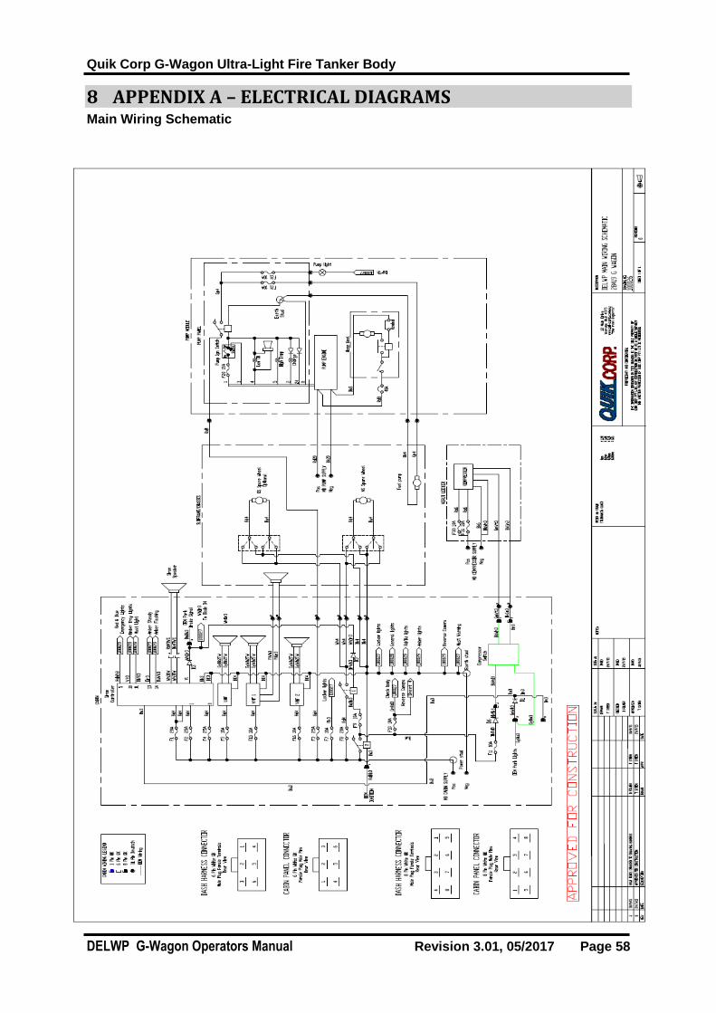
8 APPENDIX A – ELECTRICAL DIAGRAMS Main Wiring Schematic
Quik Corp G-Wagon Ultra-Light Fire Tanker Body
DELWP G-Wagon Operators Manual Revision 3.01, 05/2017 Page 59
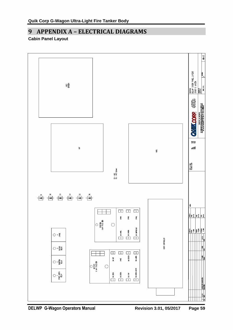
9 APPENDIX A – ELECTRICAL DIAGRAMS Cabin Panel Layout

Quik Corp G-Wagon Ultra-Light Fire Tanker Body
DELWP G-Wagon Operators Manual Revision 3.01, 05/2017 Page 60
10 APPENDIX A – ELECTRICAL DIAGRAMS Under Tray Lights Schematic
Quik Corp G-Wagon Ultra-Light Fire Tanker Body
DELWP G-Wagon Operators Manual Revision 3.01, 05/2017 Page 61
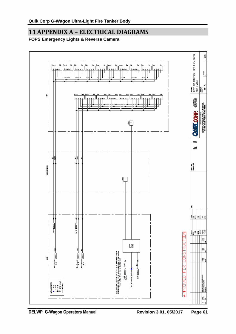
11 APPENDIX A – ELECTRICAL DIAGRAMS FOPS Emergency Lights & Reverse Camera

Quik Corp G-Wagon Ultra-Light Fire Tanker Body
DELWP G-Wagon Operators Manual Revision 3.01, 05/2017 Page 62
12 APPENDIX A – ELECTRICAL DIAGRAMS Lockers & Check Body System Schematic

Quik Corp G-Wagon Ultra-Light Fire Tanker Body
DELWP G-Wagon Operators Manual Revision 3.01, 05/2017 Page 63
13 APPENDIX A – ELECTRICAL DIAGRAMS Vehicle Lights Schematic

Quik Corp G-Wagon Ultra-Light Fire Tanker Body
DELWP G-Wagon Operators Manual Revision 3.01, 05/2017 Page 64
14 APPENDIX B – PLUMBING DIAGRAM Plumbing Schematic

Quik Corp G-Wagon Ultra-Light Fire Tanker Body
DELWP G-Wagon Operators Manual Revision 3.01, 05/2017 Page 65
15 APPENDIX B – PLUMBING DIAGRAM Fuel Line Plumbing Connection

Quik Corp G-Wagon Ultra-Light Fire Tanker Body
DELWP G-Wagon Operators Manual Revision 3.01, 05/2017 Page 66
16 APPENDIX D – SPARE PARTS
For all spare parts, please contact Quik Corp to order
1800 645 688
www.qcfe.com.au

Quik Corp G-Wagon Ultra-Light Fire Tanker Body
DELWP G-Wagon Operators Manual Revision 3.01, 05/2017 Page 67
17 Component Warranties
Warranty Policy
This document sets out the warranties that are given by Quik Corp Pty Ltd (ABN 18 081 235
556) in relation to the Product purchased from or manufactured by Quik Corp.
1. Definitions
1.1. In this warranty policy: “Quik Corp” means Quik Corp Pty Ltd (ABN 18 081 235 556);
“Customer” means the party who originally acquired the Product from Quik Corp, or
an authorised distributor, reseller or dealer for Quik Corp, for their own use.
“OEM Equipment” means the items of equipment fitted to the product by Quik Corp
and which items have been manufactured by others and have their own
manufacturer’s warranty.
“Product” means the goods or machinery that the Customer acquired and which
were manufactured by Quik Corp.
2. Warranty
2.1. Subject to clause 3 and clause 4, Quik Corp warrants to the Customer that the Product will be free from proven defects in material and workmanship for twelve months from the date of purchase by the Customer, unless a specific warranty period applies to a component listed in appendix A.
2.2. The warranty is not transferable.
3. Limitations
3.1. This warranty does not cover damages resulting from shipping and handling, abuse, accidents, alterations, normal wear or failure to maintain or use the Quik Corp product with due care.
3.2. Quik Corp does not warrant that the operation of the product will be uninterrupted or error free. The Customer must read and follow all instructions and manuals for the setup, maintenance and use of the Product. If the Customer fails to do so, the product may not function correctly and may suffer other damage.
3.3. This warranty does not extend to OEM equipment which has its own warrant and the Customer must rely on the OEM equipment warranty for any defects in material or workmanship relating to the OEM equipment.

Quik Corp G-Wagon Ultra-Light Fire Tanker Body
DELWP G-Wagon Operators Manual Revision 3.01, 05/2017 Page 68
3.4. This warranty does not extend to cover corrosion due to any cause nor to any damage to painted or anodised surfaces that occurs after the Customer takes delivery of the product.
3.5. This warranty does not cover time required to diagnose a warranty problem.
3.6. The use of parts other than Quik Corp parts for repair of warranted items will automatically negate any warranty. Warranted components must be replaced with genuine Quik Corp parts.
3.7. Repairs by an unauthorised agent will automatically forfeit any warranty. Warranty repairs must be carried out by Quik Corp or an authorised Quik Corp Dealer/Service Agent only.
3.8. This warranty does not cover transportation or insurance costs for Products needing repair or replacement of warranted components. Nor does it cover any freight or insurance costs in obtaining new parts or returning old parts to Quik Corp for inspection purposes.
3.9. The time taken to remove and re-install a warranted part or component into other brands of equipment will not be covered by the Quik Corp warranty. Only parts and labour directly attributable to the repair of the Quik Corp unit is covered.
3.10. Quik Corp does not pay for cleaning, or clean the Product, accessories or work area before or after the warranty repair.
3.11. Quik Corp assumes no responsibility for improper choice of models or where products are used in excess of rated capacities and design functions, or under abnormal conditions. We make available a free technical service to help with any product selection, application or situation.
4. Repair or Replace
4.1. During the warranty period, Quik Corp or its authorised Dealer/Service Agent shall repair or replace, at Quik Corp’s discretion, without charge for parts and standard labour, any part of the Quik Corp Product which fails because of defects in material or workmanship unless the damage arises from:
4.1.1. Failure resulting from neglect or misuse, such as improper operation, lack of required maintenance or continued use of the Product after the discovery of a defect which results in greater damage to the Product;
4.1.2. Deteriorated or failed components such as but not limited to diaphragms, O-rings, hoses, seals, electrical wiring and connections damaged by corrosive chemicals, dirt and sand, excessive heat or moisture. The Customer should ensure the type and strength of chemicals used in the Product are compatible with the design of the Product;
4.1.3. The use of accessories, hardware, or software which were not manufactured by, installed by or approved in writing by Quik Corp;
4.1.4. The use of consumable items such as but not limited to oils, lubricants, diaphragms, O-rings, hoses seals, gaskets, filter elements, flow meters, clutches, drive belts, pivot pins, paint, batteries, radio transmitters, radio relays, push buttons, switches, hose rollers, aerials, spray guns and nozzles as these items are considered to be normal wear items and are not warranted;
4.1.5. Component failure caused by not performing scheduled maintenance service such as oils, grease, failure to clean tanks, pumps, filters, spray

Quik Corp G-Wagon Ultra-Light Fire Tanker Body
DELWP G-Wagon Operators Manual Revision 3.01, 05/2017 Page 69
lines, nozzles or any other components and not tightening or replacing loose or missing bolts, nuts, fittings, shields and covers;
4.1.6. Damage or machine failure caused by carelessness or accidental damage, improper operation, inappropriate transportation or storage of the Product;
4.1.7. Any contamination or leakages caused or induced by the Customer;
4.1.8. Any use or operation of the Product outside the physical, electrical or environmental specifications of the Product;
4.1.9. Any alterations, modifications, attachments or unauthorised repairs to the Product which have not been authorised in writing by Quik Corp; and
4.1.10. Failures due to faulty or inadequate electrical sources of power.
5. OEM Warranties
5.1. All OEM (Original Equipment Manufacturer) components are covered by the Original Manufacturer’s Warranty. It is the Customer’s responsibility to familiarise themselves with these warranties, and subject to clause 7, that is the only warranty given to the customer in respect of that part of the Product.
6. Warranty Claim Procedure
6.1. To obtain warranty service:
6.1.1. The Warranty Registration Form must be returned to Quik Corp by the Customer within 14 days of taking delivery of the Product;
6.1.2. The Customer must read the Operating manual before operating the Product;
6.1.3. The Customer must provide with notice of the defect Quik Corp within the warranty period and within 14 days of discovery of the claimed problem, and allow reasonable time for replacement or repair.
6.2. Quik Corp may, at its discretion, request the Customer to deliver the alleged defective parts to an authorised servicing Dealer/Service Agent or to Quik Corp. Transportation of the Product to the authorised servicing Dealer/Service Agent or Quik Corp for warranty work is the responsibility of the Customer and is at the Customer’s expense. Alternatively, the Customer may request a Quik Corp service technician to travel to the site of the Product to effect repairs or replacement, however the reasonable travel costs (including traveling time) of the service technician must be paid for by the Customer.
6.3. Any service outside the scope of this warranty will be charged for at Quik Corp’s rates and terms then in effect.
7. Other
7.1. This warranty is in lieu of all other warranties (except those of title), expressed or implied, and there are no warranties of merchantability or fitness for a particular purpose.
7.2. Unless the Product has been purchased for personal, domestic or household use, any liability of Quik Corp to the Customer arising under statute which may not be excluded restricted or modified by agreement in limited to an amount equal to, as determined by Quik Corp:

Quik Corp G-Wagon Ultra-Light Fire Tanker Body
DELWP G-Wagon Operators Manual Revision 3.01, 05/2017 Page 70
7.2.1. Replacement of the Product or supply of equivalent Product;
7.2.2. The repair of the Product;
7.2.3. The payment of the cost of replacing or repairing the Product; or
7.2.4. Refund of the purchase price paid by the Customer.
7.3. Subject to clause 7.2, in no event shall Quik Corp or the authorised Dealer/Service Agent be liable for any loss of profit or any consequential, indirect or special loss, damage or injury of any kind whatsoever arising directly or indirectly from the Product or any defect.
7.4. The benefits under this Warranty are in addition to other rights and remedies under a law in relation to the Product.
7.5. The judgement of Quik Corp in all cases of claims under this warranty shall be final and conclusive and the Customer agrees to accept its decisions on all questions as to defect, repair and to the exchange of any part or parts.
8. Warranty period
Subject to Quik Corps warranty terms and conditions, below warranty periods apply to this
appliance.
Poly, Roto moulded tank – 15 Years
Pump – Davey FF Twin - 1 year
Pump motor Hatz 1B40 Diesel 12V electric start - 2 years
Hose reel – QCFE RFR - 3 years
Lockers – Aluminium structure - 3 years
Aluminium Fire unit Sub Frame – 5 years
Steel chassis frame – 2 years
FOPS – 5 years
Fabricated stainless steel plumbing 20 years
Ball Valves 1 Year
Electrical items (led lights, hazard lights, work lights) 1 Year
All others 1 year or OEM warranty.