MENNENhhhh Ehhmmhhhhhh · y, z cartesian coordinates in the plane of the cross-section ', a'...
76
RD-f?@ 296 THI*N-I.LED uE THEORIES WS THIRl WPLICRTIONS IN TE in1 TORSIOINL STRENST. (U) DEFENCE RESERECH ESTROLISUENT NYRLNETIC DRRTNSUTH (NOMN SCOTI.. T R VERNON ET AL UwNCfiSF JR N D EfdT - TN-SPaSF/ 131 MENNENhhhh Ehhmmhhhhhh
Transcript of MENNENhhhh Ehhmmhhhhhh · y, z cartesian coordinates in the plane of the cross-section ', a'...

RD-f?@ 296 THI*N-I.LED uE THEORIES WS THIRl WPLICRTIONS IN TE in1TORSIOINL STRENST. (U) DEFENCE RESERECH ESTROLISUENTNYRLNETIC DRRTNSUTH (NOMN SCOTI.. T R VERNON ET AL
UwNCfiSF JR N D EfdT - TN-SPaSF/ 131
MENNENhhhhEhhmmhhhhhh

1-2 114 1*61 1N
-UI **.** II ,

UNLIMITED DISTRIBUTION
I4National Defence Defense nationaleResearch and Bureau de rechercheDevelopment Branch at d6veloppement
to TE::CHNICAL MEMORANDUM 87/202
N January 198'
00
%%; .1 zs
THIN-WALLED BEAM THEORIES -
AND THEIR APPLICATIONS INTHE TORSIONAL STRENGTH ANALYSIS
OF SHIP HULLS
T.A. \Vernon -Y. Nadeau
DTI CDOISMIRON IrATEEI A *LECTE
Ap;pwved it publc 1036as MAR 2 6WD~stz'-butma Uujmited
Defence -Centre de0AResearch Recherches pour la
Establishment DefenseAtlantic / Atlantique
Canadta~7 3 t

IL7.0 W-
UNLIMITED DISTRIBUTION
* National Defence Def ense nationaleResearch and Bureau de rechercheDevelopmnent Branch et developpemnent
THIN-WALLED BEAM THEORIES a
AND THEIR APPLICATIONS INTHE TORSIONAL STRENGTH ANALYSIS
OF SHIP HULLS
T.A. Vernon - Y. Nadeau '
January 1987
Approved by B.F. Peters A/DirectorITechnology Division
DISTRIBUTION APPROVED BY
AID/TO
TECHNICAL MEMORANDUM 87/ 202
r %
Defence Centre de t
Research Recherches pour laEstablishment DefenseAtlantic Atlantique
'.w...a,.
Vaidkk,-o.

Abstract
Unified developments of the St-Venant and warping-based thin-walled beam theoriesand their application in the torsional analysis of ship structures are presented. Open cell,closed cell and multi-cell configurations are treated. The warping-based torsional theory,which accounts for out-of-plane displacements and displacement restraints, provides axialstress distributions resulting from bimoments and in general offers improved predictionsof shear stress distribution in thin-walled beams over the St-Venant theory; however, theuse of that theory necessitates a more detailed cross-sectional property evaluation. Thegeneralization of the warping function to a displacement field independent of the twist isdiscussed, as are several iterative methods of including warping shear deformations. Theapplication of the prismatic warping theory to the analysis of non-prismatic beams is dis-cussed, and the flexural-torsional beam method proposed by Pedersen is developed. Thismethod, in conjunction with a computer program to calculate the required cross-sectionalproperties, has been integrated into a general torsional stress analysis capability withinDefence Research Establishment Atlantic (DREA). The DREA system, which can accountfor geometric discontinuities in a structure, has been developed as an alternative to finiteelement methods, and is evaluated here via comparison with detailed finite element analy-ses for several prismatic beams with discontinuities. The flexural-torsional model appearsto give representative behaviour only for structures which possess considerable transverserigidity. Finally, the beam theory is applied to the stress analysis of the hull of a frigate.The shear and axial stresses predicted for the applied torsional load are quite low, despitethe existence of significant geometric discontinuities in the hull.
1%.1.
I'-

:.
R~sum6 '
Sont pr~sent6s des d~veloppements unifi6s de la th~orie deSaint-Venant et de la th6orie des poutres t paroi mince fond~e sur legauchissement ainsi que leur application l'analyse torsionnelle desstructures navales, pour des configurations A cellule ouverte, ; celluleferm~e et A cellules multiples. La th~orie des torsions fond~e sur legauchissement, qui explique les d~placements hors-plan et les limites ded~placement, donne les distributions des contraintes axiales r6sultant desbimoments et, de fagon g~n6rale, permet de mieux pr~voir la distribution descontraintes de cisaillement dans les poutres i paroi mince que la th~orie deSaint-Venant; elle n~cessite toutefois une 6valuation plus d~taill6e descaract~ristiques sectionnelles. La g~n~ralisation de la fonction de rgauchissement en un champ de d~placement ind6pendant de la torsion est6tudi~e, ainsi que plusieurs m~thodes it~ratives d'inclusion des deformationsde cisaillement de gauchissement. L'application de la th~orie dugauchissement prismatique l'analyse des poutres non prismatiques est6galement discut~e, puis la m~thode des poutres de fl~chissement-torsionpropos~e par Pedersen est 6labor~e. Cette m~thode, combin6e i un prograimme decalcul des caract~ristiques sectionnelles n~cessaires, a 6t6 incorpor6e i unsyst~me d'analyse g6n6rale des contraintes torsionnelles au Centre derecherche pour la D~fense/Atlantique (CRDA). Le syst~me du CRDA, qui peutexpliquer les discontinuit~s g6om~triques d'une structure, a 6t mis au pointcommue substitut aux m~thodes A differences finies. Son 6valuation est faiteen coxnparaison avec des analyses d6taill~es i diff~rences finies de plusieurspoutres prismatiques pr~sentant des discontinuit~s. Le mod~lefl6chissement-torsion semble produire un comportement repr~sentatif uniquementdes structures qui poss~dent une rigidit6 transversale considerable. Enf in,la th~orie des poutres est appliqu~e i l'analyse des contraintes de 19 coqued'une fr~gate. Les contraintes axiales et de cisaillement pr6vues pour lacharge torsionnelle appliqu6e sont assez faibles, en d~pit de l'existence dediscontinuit~s g~om~triques importantes dans la coque.
~16
NTIS CNR\&IDTIC !u'fiC 1AB CSOPY JiiJJ__A
NSPECTED
6 Y... . ....
.~ ~ ( b. ort(:
Ai voi; O
01A. V'l
Contents
Abstract HI
Table of Contents iv
List of Figures v
Notation Vi
1 Introduction 1
2 A Review of the St-Venant Torsion Theory 32.1 Open sections..........................................42.2 Closed section.......................................... 52.3 Multi-cell sections.......................................6
3 Warping Torsion 83.1 System of coordinates. .. .. .. ... ... ... ... ... ... ... .... 93.2 Open sections. .. .. .. .. ... ... ... ... ... ... ... ... .... 93.3 Closed sections .. .. .. .. ... ... ... ... ... ... ... ... .... 173.4 Multi-cell sections. .. .. .. ... ... ... ... ... ... ... ... .. 203.5 A Refined Beam Torsion Model. .. .. ... ... ... ... ... ... .. 213.6 Account of Shear Deformation .. .. .. ... ... ... ... ... ... .. 25
4 Application to Non-Prismatic Beanst 274.1 General Approaches .. .. .. ... ... .. ..... ... ... ... .... 274.2 A Flexural-Torsional Model .. .. .. .. ... ... ... ... ... ... .. 28
5 Implementation and Evaluation of the Flexural-Torsional Model 345.1 DREA Torsional Analysis Program Suite .. .. .. ... ... ... ... .. 345.2 Evaluation of the torsional analysis system. .. .. .. ... ... ... .... 35
6 Conclusion 37
Appendix A - Notes on the Differential Equation 56
References 60
Bibliography 62
7,
4..~~ % -- .* C* C~. ~ . .. .

List of Figures
1 Open, closed and multi-cell thin-walled beams ...................... 402 Torsion 'restraints in a hull form with large discontinuities ............... 413 St-Venant shear stresses on open and closed sections ................... 414 Warping deformation of an open section ........................... 425 Warping deformation of a closed section .......................... 426 Equilibrium of internal and external forces on an unrestrained closed cell. 437 Shear flows in a multi-cell cross-section ...... ..................... 438 Global ar ' local coordinate systems ............................. 449 Generalized cross-sectional displacement definitions ................... 4410 Forces on a wall segment ........ ............................. 4511 Transfer of sectorial coordinate pole and origin ...................... 4512 Coordinate system for the flexural-torsional model ................... 4613 Test 1: Simple box beam with discontinuity ........................ 4614 Twist angle predictions for test 1 under a torsional load (Pedersen)..... 4715 Axial stress predictions for test 1 under a torsional load (Pedersen)..... 4716 Test 2: Finite element model for comparison solution ................. 4817 Twist angle predictions for test 2 ........ ....................... 4918 Axial stress predictions for test 2 ................................ 4919 Axial stress contours of top surface showing stress concentration at the dis-
continuity ......... ....................................... 5020 Moment distribution applied to the frigate hull ...................... 5021 Twist angle prediction for the frigate hull .......................... 5122 Axial stress immediately aft of the major discontinuity in the frigate hull 5223 Axial stress immediately foreward of the major discontinuity in the frigate
hull ........... .......................................... 5324 Shear stress distribution from a traditional analysis for a cross-section of the
frigate hull. ..................................... 5425 Shear stress distribution from the warping based methods for a cross-section
of the frigate hull ......... .................................. 55Al Axial stress distribution for various k values in a clamped-free beam under a
concentrated end moment ......... ............................ 59
,.
V7.,. .- . . . . . . - - . .. . . . - - -. .. ..-. .. . - .- . .. . .. .: -. .. . . . , .- , . . . ..-. - - - - . - . . ,- , ". . ," - . ." .'. '.,.S.
. .- ,: . '.-,:. -. ... .. . .. .. .. . . .. -. .. .. ..- ... -. . .. .. .-.. . - .. , ..-.. .. . . . -... , . . -. -. .. . . . ,. - - . ... .. . . . . . ,,,

Notation
A cross-section area
b length of discrete thin wall segment
B hull breadth
c,, cZ coordinates of cross-section pole (shear center)
Cw hull waterplane area coefficient
CB hull block coefficient
D hull depth, vector of generalized displacements
E modulus of elasticity
* shear modulus
h distance from profile line tangent to shear center
IV second moment of area about the Y-axis
I, second moment of area about the Z-axis
It, product of area
I" f w2 dA sectorial moment of area
I,,, f wy dA sectorial deviation moment
I,, f wz dA sectorial deviation moment
Ihh f h2 dA central moment of area
It St-Venant torsional constant
k warping parameter = I-V EI,
I length of beam
L total hull length
m, Mn, m, distributed torsional and flexural moments
M, bimoment
vi
'p

V
n number of segments in the cross-section
nc number of cells in a cross-section
pX, p1 , pZ distributed body forces
P., Py, P, concentrated body forces
P(x) particular solution of a differential equation
qi, q2 St-Venant shear flow, warping torsional shear flow
QV, Q shear forces along y and z axes respectively
normalized St-Venant shear flow
s curvilinear coordinate along wall profile %
so, s1 arbitrary and principal curvilinear coordinate origins
SY static moment= f y dA
Sz static moment = f z dA .S..
S, statice moment =f w dA
SY static moment function = f' yt ds ,.
j static moment function = fo' zt ds .
S~f, static moment function = wt ds
t wall thickness
T total torsional moment about shear center, kinetic energy
T, St-Venant torsional moment
T,, warping torsional moment
u normal displacement with respect to the profile line
U internal energy
v tangential displacement along the profile line
w longitudinal displacement
V i,
l ,e

W potential energy of the loads
x longitudinal coordinate
Xe vector of integrable functions
y, z cartesian coordinates in the plane of the cross-section
', a' warping compatability coefficients at station i
f horizontal bending slope
- shear strain in cross-section wall
6 longitudinal deformation due to axial loads at a section
engineering strain, shear center offsetI.
17 vertical offset of a point from longitudinal axis
o warping factor
K general coefficient matrix
horizontal offset of a point from longitudinal axis
p warping moment parameter = hIhh -It
a, warping normal stress
r general shear stress
normalized St-Venant shear stress
r1 St-Venant shear stress
r2 warping shear stress
4 rotational angle
€' rotation per unit length (twist)
w sectorial coordinate
O1 frequency
41 phase angle
C(s) sectorial derivative -9a
V.
.aat%
*- . - *- .- -. ,, *. . . . . . . . . . . . . . . . . . . .. . - ' '- *

.10
.t.
1 Introduction
Thin-walled beams have found many applications in modern structural engineering be-cause of their potentially high strength/weight ratios. Much of the early development ofengineering thin-walled beam theory has its roots in aircraft design and analysis, whereweight savings have always been particularily important. Similar methods have tradition-ally been applied in the stress and vibration analysis of ship hulls, as these structures, -.
although of a different scale, are well within the dimensional assumptions of the thin-walledtheory.
The construction of larger and more novel hull forms in the past two decades has ledto a demand for better analytical tools for the prediction of ship hull flexural and torsionalresponse. While numerical techniques such as the finite element method can provide thedesired capability, the time consuming nature of that form of analysis has provided moti-vation for further development of thin-walled beam modelling methods. These more recentdevelopments in the thin-walled beam theory are the subject of this report.
There are two inherent characteristics of thin-walled beams which can be a drawbackto their utilization: the higher level of shear stress which is generally present in the thinwalls, and the tendency of such beams to warp out of plane under torsional or flexural -loading. The higher wall stresses can lead to shear buckling of very thin plate structures, aparticular concern in the aerospace industry, but not generally a problem with ships becauseof their greater plate thicknesses. The warping tendency is particularily severe in the case oftorsional loading of open cell sections, Figure 1, a cross-sectional configuration common inship hulls. In such cases, the application of the traditional St-Venant theory of torsion canlead to inaccurate stress predictions. This inadequacy is primarily a result of the neglectof the warping deformation, which is a function of the geometry of the section in much thesame manner as bending is related to the area moments of the section. In attempting toobtain a better stress prediction capability, the modern beam models for torsional analysisaccount for warping.
As suggested, the requirement for a detailed torsional analysis capability for ship hullsis relatively recent. Most conventional hulls have adequate torsional resistance simply as a -
result of the closed, cellular configuration of the shell and decks, or from the inclusion oftorsion boxes, Figure 2. However, if the cellular nature of the hull is highly discontinuous,or if large sections of the hull are open, torsional loading can induce quite high shear andlocalized axial stresses in the vicinity of the geometric discontinuities, and deformationscan be high in the open sections. This has been a significant consideration in .he designof second and third generation container ships, and torsional analysis methods for shipstructures have been developed to assess displacements and stresses in such designs. Thesemethods also have applications in the design and analysis of modern warship hulls whichoften have large discontinuities and open sections to accomodate uptakes and downtakes,
°.'-..

weapon systems, or elevator shafts. Prismatic beam torsion theories are generally used,whereby the hull is modelled as a series of prismatic segments. With a consistent derivationof the coupling and compatibility parameters required for linking the beam segments, thesesimpler models can provide stress predictions which compare reasonably well with full scalefinite element and experimental results. However, in certain cases, the assumptions onwhich these theories are generally based are not valid, and the beam theory predictions arelittle better than poor approximations of the true structural response. Unfortunately, therelaxation of the violated assumptions often leads to an intractable solution method for thecomplex geometries of ship cross-sections.
The available comprehensive literature on this subject originates mainly from Germanand northern European authors, but much of this is lacking in general context and tendsto be problem specific. As well, the notation is inconsistent and the mathematical develop-ment, with few exceptions, is often vague and incomplete. With these considerations, theaim of this report is to provide a unified development of both the St-Venant and warpingtorsion theory, emphasizing the different assumptions underlying each model. The devel-opment treats open, closed and multi-cell configurations separately for both theories andalso presents the further refinement of the warping torsional model proposed by Kollbrunner
and Hajdin(1) and discusses the iterative techniques suggested by Westin(2 ) and Pittaluga(3 ).Section 2 presents a review of the St-Venant theory, and the warping theory is developed
in Section 3.Although warping based theories can provide quite adequate displacement and stress
predictions for prismatic beams, many structures of interest, such as ship hulls, are non-prismatic. Methods of treating this problem are discussed in Section 4. As an example ofthe warping theory generalized to include longitudinal cross-sectional property variation,the formulation of the differential equations of equilibrium as proposed by Pedersen(") is also
presented in Section 4. This method, which models horizontal beam flexure and torsionaldisplacements, also accounts for larger geometric discontinuities in the structure via coupling
coefficients relating the bending and warping functions on either side of a discontinuity. Thelarge cutouts for intakes and uptakes in warship hulls are examples of such discontinuities.
A modified version of the fiexural-torsional solution algorithm presented in Section 4is used in conjunction with several programs developed at Defence Research Establish-
ment Atlantic (DREA) to provide a simpler alternative to finite element analyses of thin-walled structures under torsional loading. This system, described in Section 5, utilizesthe TPGEOM( s ) program to establish a cross-sectional data base for a structure, and theSCRAP 6 ) program for calculation of all relevant cross-sectional properties. These prop-erties are stored by section, and a beam model is constructed for use in the formation of
the equilibrium equations. The sectional shear and axial stress distributions are also cal-culated and displayed by the SCRAP program. These distributions are scaled from theinternal forces in the beam calculated from the TORSON program, which provides a nu-
2
*,-.. ..

merica] solution of the coupled differential equilibrium equations. The TORSON programwas originally obtained from the Technical University of Denmark.
Section 5 also describes an evaluation of the displacement and stress prediction ca-pabilities of this system by comparative analyses utilizing detailed finite element modelsfor several simple prismatic thin-walled beams. These studies have indicated that the as-sumption inherent in the beam methods of no in-plane distortion is a very critical one, aconclusion also reached by other authors.(2, 7 ) Although potentially very significant in un-stiffened structures, the loss of accuracy due to cross-sectional distortion will be reasonablynominal in a beam me'hod analysis of a typical warship hull because of the large configura-tional stability provi, d by the numerous deep web frames and transverse bulkheads. Thesystem has been utilized in a study of a frigate under an assumed torsional/flexural load,the results of which are also presented in Section 5. Since no comparative solution existsfor this hull, these results remain unverified.
2 A Review of the St-Venant Torsion Theory
Traditional torsional analyses of ship hulls have utilized the St-Venant theory of torsionto predict the shear stresses and twist angles of the hull girder under a specified loadingdistribution.(8 ) If the hull sections are largely cellular in nature, the shear stress and twistangles will generally be small, and their predictions via the traditional methods can beconsidered accurate to at least the same level as the description of the loads. If the structureis of a mainly open or mixed nature, the stress predictions from the St-Venant theory canbe in error, particularily in the vicinity of large geometric discontinuities or longitudinaldisplacement restraints such as torsion boxes, which cannot be properly included in thatapproach. These discontinuities and stiffening structures inhibit the free warping of thestructure, and can lead to significant axial and secondary shear stresses superimposed onthe St-Venant shear stress distribution. An example of the influence of a discontinuity onthe stress distribution near the discontinuity of a typical ship hull is presented in the finalsection of this report.
A physical concept of the phenomenon of warping is useful in visualizing the differ-ence between classical torsion (St-Venant) and warping torsion. Subsequent discussion willpresent the mathematical treatment of these two subjects.
A St-Venant torsional moment generates a shear stress pattern on the surface of thecross-section as illustrated in Figure 3. For a closed section, a shear flow is able to 'circulate' %
around the cross-section and the shear stress is constant over the thickness. For an opensection, the shear stress assumes a linear distribution over the thickness with a zero average.The notion of St-Venant torsional stiffness can thus be considered as the effectiveness withwhich a given cross-section will generate a shear stress distribution on its surface to oppose
3.

-. 7-
F
the applied torsional moment.To illustrate warping torsion, consider an open beam section, Figure 4. The cross-
section undergoing rigid body rotation must also undergo longitudinal displacement asa kinematical consequence of this rotation. In other words, the tangential displacementof an element of the surface of the cross-section must be accompanied by a longitudinaldisplacement w if the generator G is not to stretch. If this longitudinal displacement isrestrained, a new resistance will have to be countered to deform the body, adding to theoverall torsional stiffness. Additional stresses will thus be induced in the beam. Accordingly,the warping torsional stiffness of a cross-section can be viewed as the relative capacity ofthe section to generate a stress pattern on its surface that will effectively resist a torsionalmoment when the section is longitudinally restrained.
As discussed, a shear flow is free to circulate around the contour of a closed section.Observing an element of the wall, Figure 5, it can be seen that equilibrium then requires alongitudinal shear flow. This will cause a shear deformation in the plane of the wall and thisdeformation will partially cancel the warping. For this reason, the warping displacementin closed sections will be smaller and consequently less affected by a longitudinal restraint.Hence, closed sections will generally have a smaller warping torsional stiffness than opensections. For certain geometries such as squares and circles, the shear and kinematic defor-mation completely cancel each other, and no warping occurs.
The St-Venant theory of torsion assumes that the section is free to warp. For elasticbehaviour, a first order differential equation can be derived,(P) which relates the St-Venanttorsional moment to the twist,
T. = Gt' (1)
where T, is the St-Venant torsional moment, G is the shear modulus of the material, Itis the St-Venant torsional constant of the section, and 0' is the twist (rotation per unit
length). This relationship is valid for both open and closed cell configurations; the onlydifference occurs in the value of It, the St-Venant torsional constant. The calculation ofthis constant for the cases of open, closed and multicell sections is briefly presented below.
2.1 Open sections
For an open section generated from a series of folded segments, It can be approximated(10)
as I,, where,1obt3
Ito t ds (2)
or, for numerical calculation,
s=1
4p"
p
pp2
-,
. . . -

'.' ,'*
where b and t are respectively the length and the thickness of the n discretized elementsof the cross-section. The stress has a linear variation over the thickness with a zero mean,and its maximum value at the edge is approximated by,
(7')maz - (4)
2.2 Closed section
A closed section is considered here to be a single cell cross-section of arbitrary shapethat contains no free ends. For such a section, the torsional constant is composed of twoterms:
(1) It, as for an open section and corresponding again to a shear stress .
varying linearly over the thickness;(2) If, corresponding to a shear stress which is constant over the thickness. %
The closed cell torsional constant It can be found from consideration of the overall equilib-rium and potential energy. Consider an element of the wall that can be of varying thickness, %Figure 6. Since the section is assumed to be free of longitudinal restraint, there should beno axial stress on the surface. Equilibrium in the axial direction requires,
(Tbtb - 7.t.)dx = 0 (5)
which implies, for rt = q ,that= qb (6)
indicating that the shear flow must be constant around the section. It should be noted thatthis conclusion was reached because of the assumption of no axial stress over the thickness. 1This is an important characteristic of St-Venant torsion that differs from warping torsion,as will be shown.
Refering to Figure 6, the value of the St-Venant shear flow q, can be found from theequilibrium of internal and external forces. We have,
dT, = hql ds (7)
since . ""'
dA = -hds (8)
We have, after integration,
T. = 2qA (9)
5 . .
. ~ ~ ~ ~ ~ ~~~~~ % .* , .. . . . . . . . . .
*Z~t% % %

and hence, TaY= (10)
The work done by the applied forces must equal the work done by the internal forces.
1Td = dxf r7/ytds (11)2
since
T~d -- x f(r 1 )2
Td¢ = df /-u-t ds (13)
where the j indicates integration around the complete cell. Substituting equation (13) intoequation (10) gives,
T, = It0' (14)
where,4A2 '
It 4A2 (15)f
In most sections containing closed cells, If is many orders of magnitude larger than Ito, andthe latter is generally neglected.
2.3 Multi-cell sections
For a section composed of a number of cells, the total St-Venant torque will be equal to thesum of the torques contributed by each cell,
ne
T. 2(Aql)i (16)
This indeterminate problem can be solved by assuming that the shape of the section isassumed to remain unchanged. This implies that all cells have the same twist,
Ol = 02 = 03 ... = O'o = of (17)
From equation (13), the twist can be expressed as,, 1 f(q').
0 f 2= G f q- ds (18)
6
J~~~~~~~~~~~~~~~~~~~~~~~~~. .5p,-. . . .- .....................................................

T7%,
woa .e s*, °.-
•
Letting,,',,-
'= €, ~ ~~~(19) , .. '.,-.
we obtain tbe system of equations, ]
-ds =2AiG i =1,nc (20)
Developing the integral for cell i gives,
ds ds -] ds . 2AIG (21)qi - - q -t "'
tt " "'
where " and are the constant unit shear flows around cell i and j, respectively andfij represents an integration performed along walls common to cell i and j, Figure 7.The integrals in the above expression can readily be calculated by a cross-sectional analysis " Zprogram, and equation (20) can be expressed as a matrix system for numerical computationas,
[ic ( ) = 2G (A) (22)
where,ds (3
cell i
ds- (24)
Equation (16) then becomes,nc 1.* ,*..tV
T = 2A, (20 G [,c] ' (A)), (25)
Rearranging,T.= GIt' (26)
where, -It = 4(A) [c]- ' (A) (27)
For a specified T8, the twist can be obtained and the St-Venant shear flows (ql)i found from,
(ql)i = 4' i = 1, nc (28)
in which T has been obtained from the solution of the matrix system of equation (22). Itcan be observed that equation (27) is simply the general form of equation (15). N
V, % P-
.-- ,.-

Although not discussed here, the calculation of the shear stress distribution for multi-cellsections under transverse shear loads follows a similar procedure to that outlined above. Inthat case, a zero twist is assumed for each cell and the shear flow is written as the sum of an'open' cell shear flow and a constant correcting flow. An analogous matrix system relatingthe open and correcting shear flows can be developed, which utilizes the same coefficientmatrix [n] as above (see, for example, Reference 11).
3 Warping TorsionC.
The St-Venant theory of torsion discussed in the previous section has been widely usedto predict shear stresses in beams, and the assumptions on which it is based are realisticallyaccurate for thick-walled or solid sections, or sections which have no warping restraint. Inthe case of thin-walled sections, the assumption of free warping is often a poor one for tworeasons. The first is that such sections are prone to warp and the second is that this warpingis usually restrained in some way. These restraints provide additional torsional stiffness butgenerate secondary shear stresses in the vicinity of the restraint which can alter the overallstress distribution significantly.
Warping restraints are typically points of global fixity or internal points of attachmentof restraining structure. In non-prismatic beams, the geometric discontinuities themselvesare relative restraints, and the incompatibility occurring in the warping displacements canlead to additional shear and axial stresses. In the case of ship hulls, such discontinuitiesexist at large hatch openings, and wherever cellular sections abut open sections. As withother forms of loading, abrupt changes in geometry generate stress concentrations.
Whereas the St-Venant theory provided a simple first order differential equation relatingthe applied load and displacement, it will be shown that the inclusion of warping results .in a fourth order differential equation. This equation must be solved for the distributionof twist and its derivatives to obtain sectional stresses in the beam. This section presentsthe derivation of the equation for a prismatic beam. Two assumptions underlie all of thedevelopments that follow:
(1) The beams contain only thin walls. Accordingly, warping displacements andstresses can be assumed constant over the wall thickness.(2) The shape of the cross-section remains unchanged; no transverse deformationoccurs in the cross-sectional plane under the applied load.
A third assumption will often be made about the shear deformation in the plane of thewalls. It will be outlined as each case arises.
The development is in two parts; the first treats open sections and draws heavily on the
8
%.
C . - .' .I

development of Vlasov,( 12 ) and the second treats closed configurations. For the simplestcase of an open section, warping torsion will be studied in parallel with other states ofloading since bending and warping torsion are similar in their mathematical formulation.Thus, the latter can be understood as part of a general theory of thin-walled beams. Asmore complicated cases are treated, the development will consider warping torsion only.Finally, multi-cell sections are presented as a generalization of the closed cell development.
3.1 System of coordinates
A right-handed system of coordinates will be used, Figure 8, with the cross-section in theY - Z plane, Z vertical, and axis 0 - X being any axis of the beam parallel to the axis of thecentroid. Each point on the surface of the cross-section can therefore be determined by thetwo coordinates y and z. Because the beam is thin-walled, a more convenient coordinate,s, can be defined as the curvilinear distance along the wall profile from an arbitrary origin.In this case, the positive direction is taken as counterclockwise with respect to the origin ofthe cartesian system of coordinates. Once the origin of the s-coordinate is established, the
functions y(s) and z(s) are well-defined for the complete cross-section.
3.2 Open sections
For open sections, an assumptirn (30) in addition to (1) and (2) above is made:
(3) The shear deformation 1, in the plane of the walls (plane xs of Figure 6) can
be neglected."%S.
It was stated in the previous chapter that for an open section, there is no St-Venant %
shear flow circulating around the cross-section. Instead, the shear stress assumes a lineardistribution over the thickness with a zero average. Consequently, equilibrium of a wallelement does not require longitudinal shear stress and there will be no longitudinal sheardeformation caused by a St-Venant torsional moment. In the case of warping torsion,the warping shear stress will be assumed constant over the thickness, in accordance withassumption (1). As a result, there will be a certain amount of shear deformation in theplane of the walls caused by a warping torsional moment. Therefore, the consequence ofassumption (3a ) is the neglect of the longitudinal shear deformation but not the longitudinalshear stress nor the axial deformation caused by a warping torsional moment. 'S
With reference to Figure 9, the displacement of any point on the cross-section can
be expressed with respect to the displacement of an arbitrarily chosen point A, which isassumed to be rigidly connected to the cross-section. In the figure, C(x) and 17(x) representthe projections of the rigid body displacement of point A on axis 0-Y and 0-Z respectively
9
,.
J"~~ 'r%
'e~r , .%"

for a given section, for x constant. These functions of x then represent the space curve thatan axis of the beam passing through point A assumes after deformation.
Let O(z) be the rotation of the section in its own plane (Y - Z). The displacement inthe plane of the cross section of any point B located on its surface can be expressed usingassumption (2), which allows us to treat the cross-section as a rigid body. The kinematicsof rigid body motion can therefore be applied, giving,
G = C(X) - (zb - a.)O(z) (29)
17b = 7W - (Yb - a,)O(x) (30)
The general vector representing the displacement of point B can be expressed using thethree components u, v, w, as illustrated in Figure 8. Displacement u is directed along thetangent to the profile line with positive direction given by the s coordinate; w is directedalong the axis of the beam with positive direction given by the X-axis; v is directed alongthe normal to the profile line with positive direction given by the requirement that vectors
u, v, w form a right-handed coordinate system.Let a(s) be the angle that the tangent to the profile line makes with the 0 - Y axis,
Figure 9. Let h(s) and g(s) be the length of the perpendiculars from point A to the tangent
and normal of the profile line respectively, at point B. Components u and v can be foundfrom equation (29) and geometrical considerations, giving,
u(z,s) = - (x) coscC(s) - r(z) sin a(s) + O(x)h(s) (31)
v(x,s) = -C() sin a(s) + tl() cos a(s) + (x)g(s) (32)
Tu this point, only kinematic relations have been used, giving the state of displacementin the Y - Z plane. It remains to determine the longitudinal displacement w. To do so,use will be made of assumption ( 3 ) of negligible shear strain in the walls of the beam.
Expressed mathematically, this condition is,
au 49wa w = -Yz' =0 (33)
Solving equation (33) for w yields,
w (Xs) = 6(X) - - ds (34)ax
where b(x) is the longitudinal displacement of the cross-section at point s. of the s-
coordinate.
Equation (31) gives,
auTd = -'(x) cos a(s) ds - ?7'(x) sin a(s) ds + 0'(x)h(s)ds (35)
10
..5
.5
p.
*5m
%*..**. **** % *, .*.~ .. **. ... . . . . . . . . . . . . . .-. .

. ".
where the prime notation indicates differentiation with respect to x. Observing that,
cos ck(s) ds = -dy (36)
sin a(s) ds = -dz (37)
and defining,h(s) ds = dw (38)
substitution of equations (35), (36) and (38) into (34) yields, after integration,
w(xs) = b(z) - '(z)y(s) - ri'(z)z(s) - O'w(s) (39)
For specific points A and so, w(s) is a uniquely defined function of s, just as y(s) andz(s) and, in fact, w(s) corresponds to twice the area of the triangle formed by points A, soand s. This function of s is commonly called the sectorial coordinate, point A is called thepole of the sectorial coordinate and point s0 is the sectorial origin. The line that connects . .
"
point A to point so is defined as the fixed radius vector and the line that connects pointA to the variable s is defined as the mobile radius vector. These vectors define the signconvention used for the integrations involved in the calculation of cross-sectional properties.A contour increment is considered here to be positive if the mobile radius vector movescounterclockwise. This sign convention can be included in the definition of the sectorialcoordinate, equation (38), if the s-coordinate is chosen in the proper fashion; that is, if itspositive direction defines a counterclockwise movement with respect to pole A.
The first term of equation (39) represents a uniform axial stretching, and the secondand third terms represent bending of the beam. The last term is due to the warping ofthe cross-section under torsion, and represents the displacement of the cross-section out-of-plane. The similarity of the bending and warping terms is evident and this analogy isuseful in dealing with the less familiar problem of warping torsion.
For elastic behaviour, the axial stress in the beam is given by:
u,= Ee =E (40)
Substituting from equation (39),
oa.(z,s) = E(6'(z) - "(z)y(s) - 17"(z)z(s) - 0"(X)w(s) (41)
The tangential shear flow is found using the condition of equilibrium of a wall element, ".Figure 10. If there are no body forces, .'.-
t- + t- =0 (42)ax (9s
. . . . . .. . . .. *- * . . .• -. ,.- .- - . ' -" " -"

Then,
tro = - /-Ox t ds + (tr)o (43)
If the integration is commenced at a free edge, (tr)o is zero. Substituting equation (41)into (43) and integrating gives the shear flow as,
trz, = q(z,s) = E(-b"(x)-(s) + "'"(s) + r7'(x)-(s) + "'(x)SZ(s)) (44)
where,
k(s) = t ds (46)
TY (s) = yt ds (46)
YZj(s) = wt ds (48)
These quantities, called static moments functions, are determined from an integrationcommenced at a free edge, following an integration path that leads inward in the section.The condition of a zero algebric sum of the shear flows is used at segment intersections(nodes) to continue the integration. For the case of pure torsion, the shear stress of equa-tion (44) is often referred to as the secondary shear stress r2 , where,
tr2 = q2 = EO'(x)S.(x) (49)
The derivation of this stress assumes that an axial stress exists in the wall. In the pre-vious chapter, the St-Venant shear stress was found assuming the absence of any normalstress; therefore, these two stresses are of a different nature. The St-Venant shear stress iscommonly called the primary shear stress rl. The total shear stress is the sum of r1 andr:, and the relative distibutions are functions of the geometric properties and the warpingrestraints in the system. In an open section, the total shear stress is then the superpositionof a constant and linearly varying distribution across the wall thickness.
In the development of u(x) and r,, four unknowns are included: b(x), C(x), 77(x) and6(x). These unknowns can be found from the requirement of equilibrium of the completebeam.
Consider a strip of the beam of length dx, Figure 10. From equilibrium, we have,
ZF, =0 - (t dx ds + p. d = (50)
12
%.

ZFy =0 IA ax cos adx ds + pdx 0 (51)
Z F2 =0 ] sin cedx ds+ p, dx :=0 (52)IN
Z MA =0 J aXr)hxs mx T= (53)
Here, p., py and p-. are the distributed forces acting on the section, and m is the totaldistributed torsional moment. Since the St-Venant shear stress is not included in r, itsresulting moment, the St-Venant torsional moment T, can be introduced separately in the -
equilibrium equations. Dividing equations (50)-(53) by dx and using equation (36), we canintegrate by parts to obtain,
fJAO' dA+ p =0 (54)
[a~r)]Ja(55)[91 2 1 a r IA T axrt
L8ZIA ~ .s 8z +PzO(56)a xrt as 8(tx d
[~~ axM~w[a ++-T" -0 (57)
where dA =tds.
The first component of the last three equations is evaluated on the limits of the surface,the free edges. These terms all vanish identically since LU = - nafe deweerxis zero everywhere. Substituting from equations (41) and (44) for a and r, we have, afterrearrangement,
-A" +s" S s" sk'- (58)E
S 611 + ICif+ 'YZ1?ff + I 4? - E P (59)
S~ "' Ize" + I 1 7r" + I__ ? fil -z (60)E
S6~ ~ + ~ +IwL~4?""= r GI 1,Sbf+ wC11+Izflf+E + E (61L)
Equations (58)-(61) are derived for an arbitrary coordinate system but can be more conve-niently expressed if a coordinate system is chosen such that,
Sy S"= IZ =0 (62)
13
.%%. %Pon

- .. lt .. w~ -- -~ .&-.. . . . ~ . . , . .. .- * 5
and,
S' = A. 0 (63)
Equation (62) is satisfied if coordinates y and z are expressed in terms of the principalaxes of the section. The requirements of equation (63) define the pole and the origin ofthe principal sectorial coordinate. Assume point C, Figure 11, is a pole that fulfills theseconditions. The sectorial coordinate with respect to pole C can be expressed as a functionof the sectorial coordinate with respect to an arbitrary pole A by geometric relations,
WC = WA + (c, - a,)y(s) - (c, - a,)z(s) + (c. - a,)z(so) - (c. - a,)y(so) (64)
where y(so) and z(so) are the coordinates of the sectorial origin for both poles (wc(so) =
WA(so) = 0). Multiplying by the functions y(s) and z(s) in turn, and integrating bothequations over the sectional area, these relations reduce to,
(cz - az)1z + WAy dA = 0 (65)a
- (c,, - a1) -I- JWAZ dA 0 (66)
The coordinates of the principal pole at C are then,
c= a. + 1WA. (67)'V
WA V (68)
It can be shown that the principal pole of the sectorial coordinate is also the shear centerof the section(12) .
The principal sectorial origin s, can be found from the requirement that S, = 0 inthat system. Using the geometry of Figure 11, we can express the sectorial coordinate withorigin at s, as a function of the coordinate with origin at an arbitrary point s0 as,
W(s,, S) =W (sos ) - W(so, si) (69)
where it is now assumed that w is calculated with respect to the principal pole. Multiplyingthe above expression by dA, applying the above vanishing criterion, and integrating overthe sectional area gives w(so, s1) as,
W~so, SO) =-S"Cso, s) (70)
14
40o.
%U

,% %
S., . ,*
.
We can use equations (69) and (70) to redefine the sectional properties in terms of this *'.-
principal sectorial coordinate. Using this system, the set of equations (58)-(61) reduces tothe more familiar form,
EAS" = -PZ (71)
E =,C"' py (72)
E "= p2 (73)
Elww,¢"" - GIt¢" . (74)
It is instructive to define generalized forces in terms of the global degrees of freedom ofthe beam: longitudinal stretching, bending in the two directions and twist. Accordingly, Ithese forces can be defined as the work done by the stress fields of a and r moving through a -unit global displacement. In the case of longitudinal stresses, the internal work done arisesthrough the local w displacement and the force system is given as,
F = Iaw dA (75)
Substituting equation (39) and letting 8 = 1, 1' = -I, 7' -, and €' = -1 respectively, '
the four generalized force components of F become,
N f a dA (76) ..
M =IA y dA (77,
a, ] zZ dA (78)
M,= I, w dA (79)
The first three quantities are recognized as the normal force and the bending momentsacting on the cross-section. The fourth quantity is specifically related to the warping andis called the bimoment. Although it represents a real state of stress, it results in no netbody force since, from equation (63), the axial warping stress distribution is seen to beexactly that of the principal sectorial coordinate which is skew symmetrical. This stresswill therefore have no influence on the global equilibrium of the complete beam. For thisreason, the bimoment is often referred to as a self-balancing generalized force system.
Substituting the expressions for a from equation (41) into equation (76) and using theorthogonality conditions of equations (63) and (65), equation (41) can be rewritten as, ,
N~ Mu M2 Mi,(80A - M y + z + )1
15 - .. ,
. .. -V
-.- - :- .. -'-.. . - .". '.. ---- . . ' '.' . - -- " ". , .. '- ..- --.-.- '-1~. '. -" " - '-- ,,', .- - . ..-. " ,-",J.J.V.- % .. . -.. - . , . . . *.. .. . - . , . . . . . , . . . . . . . .. . . . - . , : . . . . - . .-. ..-* . , - .- . , - . . - . . , -. . . . , - . .% . .. . . . . .

The same procedure can be followed to define the generalized forces that correspond tothe shear stress r. This stress acts along the displacement u, given by equation (31). Wedefine:
Q= A q dy (81)
QZ = fA q dz (82)
= IA qd (3T= dw (83)
For the case of transverse loading only, 8" = 0, and after substitution of equation (44)into (81), equation (41) can be written as,
q Y Ty+ 9. 3- + ,-)(84)
where,= EI ... (85)
QY = -EIzC" (86)
Q. = -EyIv7" (87)
This expresses the total shear flow in the wall in terms of the applied loads and generalizedcross-sectional properties analogous to that of traditional beam flexure theo. '. The warpingtorsional moment T, characterizes the effect of the secondary shear stress distribution onthe cross-section, and its magnitude reflects the relative warping stiffness of the section.Equation (74) can then be written as,
T = T. + T. = GI,¢' - EI,¢" (88)
The total applied torsional moment is thus the sum of the St-Venant and the warping tor-sional moments, and at each section, there is a specific distribution of T, and T" dependenton the relative St-Venant and warping stiffness.
Equations (71)-(74) are the differential equations of equilibrium to be solved for a pris-matic open section. For the torsional equation, a unique solution can be obtained for abeam of length I in the general form,
CI + C 2 x + C 3 sinh( ) + C 4 cosh(-) + P(x) (89)
16
7J

IV N" 4%1 Nn A.-
where P(x) is any particular solution and the parameter k is defined as,
G.p.k= I (90)
The coefficients of the general solution are determined from the application of the appro-priate boundary conditions (See Appendix A). Once the distribution of O(x) is known,sectional stresses can be calculated from equations (41) and (44).
5*.
3.3 Closed sections
In a closed, single cell system, the St-Venant shear stress can be considered constantacross the wall thickness, in contrast to the open section in which the stress varies lin-early with a zero mean. This non-zero mean wall stress generates a longitudinal sheardeformation. Moreover, this shear deformation cannot be neglected in this case because itsexistence is required by the condition that the net longitudinal displacement must be zerofor a complete circuit around the cell. To account for the shear deformation, assumption(3') of section 3.2 will be reformulated:
(3b) The longitudinal shear deformation in the walls is caused by the primary shear "-
stress only; the additional shear deformation caused by the secondary shearstress can be neglected.
Using the new assumption, equation (33) becomes,
au aw r1 (91)- + - = " ° - (9 1 ) 6
For convenience, we can define,- T (92)
t GI¢'
where T is then the St-Venant shear stress for a unit St-Venant torsional moment. Usingthis definition, and noting that the shear strain -, always opposes the kinematic rotation,equation (35) can be written,
ds -c'(x) cosa(s) ds -'(x)sinu(s) ds- '(x)(h(s) -qIt) ds (93)Fra dxcrs-scioth tr ,:,"x(hs
For a given cross-section, the term It is well-defined and depends only on the geometry ALof the section. It is possible to include directly the results of the previous section if the
17

sectorial coordinate is expressed in the more general formulation,
W (s) = (h(s) - 1 It) ds (94)
which reduces to equation (38) for an open section since is then zero. Equation (94) ismore properly written as the sum of two terms,
W(S) h(s) ds -j d, (95)
since, in fact, h(s) is a scalar quantity while fIt is a vector tangent to the s-coordinatebut not necessarily in the same direction. Here again, the positive direction of the 8-coordinate gives a counterclockwise rotation of the mobile radius vector with respect tothe pole. The positive sign of the unit St-Venant shear flow is taken as counterclockwisearound the cell. Written thus, the expression for the longitudinal displacement w(x, s) fromequation (39), remains unchanged, and the formulation of the expressions for the principalsectorial coordinate and the axial stress is exactly as outlined in the previous section.
For a closed section, the net warping around a closed path must be zero,
dw = 0 (96)
It is important to check that this requirement is embodied in assumption (3b). For the sakeof clarity, consider the case of pure torsion. We have, for a closed section, from equation (15)
T.= f qh ds (97)
where,It = 4A (98)
hence,2AO'G
(99)
Recalling the definition of q, we have,
J ItO' ds = 2A4' (100)
or, equivalently,
f t~ ds = 0'fh(s)8ds (101)
18

which is exactly satisfied by enforcing equation (96), using the definition of the sectorialcoordinate of equation (95). J
For the closed section, the starting point for the integration of equation (43) can nolonger be a free edge and the constant of integration cannot be taken as zero. However, thisconstant can be found in the following manner. Again, for simplicity, consider pure torsion.The secondary shear flow is then,
q2(z, s) = E(C"'(x)(s)) + (q2)o (102)
An arbitrary starting point can be chosen for the integration of S (s) to find the first term.This is equivalent to cutting the cell open at this point and finding the corresponding sheardistribution of the 'open' section. We define,
q2 (X, s) = q; + (q2)0 (103)
where the (q2)0 is a constant correction factor. According to assumption (3'), the longi-tudinal shear strain caused by the secondary shear flow is negligible. In support of thisassumption, it is cons'stent to determine the constant shear flows in such a manner that q2gives no contribution to the shear deformation of the cell,
2 ds = -ds = 0 (104)
Substituting equation (104),
(q2)o - ds (105)
hence the complete shear distribution in the cell can be found once (q2)0 is calculated.The warping torsional moment is,
T. q2h d f(q; + (q2)o)h ds (106)
According to equation (94),
h(s)ds= dw+ !It ds (107)t
substituting into equation (106),
T. (q; + (q2)o) dw + (q; + (q2)o) 11 ds (108)
The second integral is zero from equation (104). Performing the integration on the lineintegral of s by parts gives, for the first term,
(q; + (q2)o) ds = (q + (q2)o)w]A- j ws a(q; + (q2)0) (109)
19,'
.g
as-""s
,"e", ,:., fe a.. . # ,.., . e *a e .e eZ. ¢e" .. , . . e" .e e"..". - ',', ."€, ,.,-..%,0".. ' ,.. '..,,.-

I
Since the integration is performed for a complete path, the first term on the right is zero.The constant correction shear flow (q2)0 can be dropped as it is constant, leaving,
T.= - = -E w2t ds = -El,¢' (110) .%
By comparing this expression with equation (87), we see that the expression for thewarping torsional moment is unchanged. The differential equation is then, as before,
T = T, + T. (111)
T = Gh#' - E1..0.. (112)
with the value of It and I, as appropriate for the closed cell, and the same general hyper-bolic solution form is obtained. Once known, the distribution of 0 and its derivatives canbe used to scale the sectional shear and axial stresses, where these distributions are givenfor the case of pure torsion as,
qtotat = G-t + Eo"-i(s) + (q2)0 (113)2A
and,
-xEk" h(s) ds - I dsj (114) 5
3.4 Multi-cell sections
Multi-cell sections can be treated as a generalization of the theory for a single cellcross-section, and the development leads to the same differential equation. The sectorialcoordinate is again given by,
W(s) f(h - It) ds (115)
In this case, for a given cell wall, the unit shear flow is the algebraic sum of the constantSt-Venant unit shear flows corresponding to each cell of which it is part. Here again, aconsistent sign convention must be observed. Once the principal sectorial coordinate is
'5defined for the cross-section, all of the relevant properties can be calculated exactly asdiscussed in the previous sections.
To find the stress distribution in a multi-cell section, nc constants of integration must befound, where nc is the number of cells in the section. The requirement of zero net secondary
shear strain is enforced for each cell. In terms of stress, this gives,
fdsq-0 1,nc (116)
20
........... .. ... ... ...... ... ... ... .. .,.

' .° " , m-. ..
This allows the formation of a matrix system, the solution of which gives the required (q2)0correcting factor for each cell. Using the same notation as in section 3.3, we can developfor cell i, ds fds d
q2 - + (q2)0i t - - "* = 0 (117)-f t .T i
where q; is again the shear flow distribution derived from equation (103) after cutting the .
cells open. In matrix form, equation (117) can be written,
N ((q2)0) = (q;) 11)
where it can be seen that the K coefficient matrix is exactly that derived for the solution of athe St-Venant shear flows.
Solving for the (q2)0, the warping secondary shear stress can be found from equa-tion (113) and the axial stress distribution from equation (114). The total shear stress -,. *..
distribution is the sum of the St-Venant, transverse, and secondary warping shear stressdistributions. The longitudinal stress distribution is given by the sum of the two bendingand the axial stress distributions.
3.5 A Refined Beam Torsion Model
The development of the previous beam torsional model has been consistent with mostclassical beam theory, wherein equilibrium is enforced despite the neglect of secondary shear- "deformations. This leads to the assumption that the warping deformation is proportionalto the twist, as in the case of unrestrained warping. A more general form of warping dis- "tribution has been proposed(') in which a displacement field proportional to the sectorial "..coordinate, but independent of the twist, is assumed. This new degree of freedom is com-monly called the generalized warping function. Unfortunately, such an assumption can leadto unsatisfactory local equilibrium conditions, and the warping stress distributions pre-dicted by this theory are not completely reliable;(13) however, the sectional loads calculatedfrom the refined theory can be used in the classical stress equations to improve the stressprediction accuracy of that model. F. .*f.*
For simplicity, consider the case of pure torsion. Since no assumption is made about theshear deformation in the x - s plane, Figure 6, equation (91) is,
au awaz+ -s = -, (119) K.K-4:.-
The expression for the tangential displacement u remains unchanged as the assumption of noin-plane distortion of the section is retained. For pure torsion, we have from equation (31), . .
u~xs) = O(x)h(s) (120)
21
.W .

The longitudinal displacement w will again be assumed proportional to the sectorial coor-dinate and to an arbitrary function of the longitudinal position x, rather than the twist
w(Xs) = -O(z)w(s) (121)
where O(x) is the defined as the generalized warping function. The negative sign is intro-duced to retain the similarity with the previous development. Substituting equations (120)and (121) into equation (119) gives the shear deformation as,
-, = O'h(s) - O(x)c.(s) (122)
where the overdot indicates differentiation with respect to s,
(s) = aw = h~s) - Vias t
The stresses can then be expressed as,
awa(z,s) = E- = -EO'(x)w(s) (123)ax
r(x, s) = G-yz, = G(4'h(s) - O(x)&,(s)) (124)
where r now represents the complete shear stress in the cross-section derived from anassumed displacement field. The shear center location is not affected by these new assump-tions, and can be found in the same manner as previously discussed. The total torque onthe cross-section is,
T = f h(s)r(x, s)t ds (125)
Substituting from equations (122) and (123), and using the relation,
f 2q,A (126TItht ds = - ds = I -t (126)f G~ G,0 =I
we have a differential equation in 4 and 0,
T = GhhO'(x) - G(Ihh - 't)0 (127)
or, more generally,GhhO" - G(hh - I)9' + m = 0 (128)
where,aT8x
22
S.
a,
.. °' ' -. . - 4 o a '• ~ ,
,- . ° * . *. ° . * * . * • . . . " •- . . .. . . . . .

and,
ihh h'tds (129)-
is called the central moment of area. Strictly, equation (126) is valid if only the closedcell contributions are important in the calculation of the St-Venant modulus. This is anacceptable assumption for most ship hull analyses, but will introduce inaccuracy in theanalysis of predominantly open configurations.
The differential equation contains two unknown functions O(x) and O(x), and anotherrelationship is required before a solution is possible. The principle of virtual work can be ".
used to establish a further relationship between O(x) and O(z) based on the assumptionof axial equilibrium. Away from local end effects, the internal virtual work of the shearstresses can be equated to the work done by the external forces moving through a virtualdisplacement field. The incremental axial stress in this case can be considered as the "external load, Figure 10. In the general case, this stress will also include the contributions . :"
from bending and longitudinal loads. We can write, for a unit 0,
[t ds dx = rf f t ds dx (130)
f ., -x %/.
where Z and i represent virtual displacement and strain fields respectively. Using equa-tion (123) in (130), we have, after substitution and cancelation,
Eo"(X) f w2 t ds + GO'(x) f h t ds - GO Jf 2t ds -0 (131). ' -
Expanding the second integral, we obtain,
J hjt ds =fh(h - t-)t ds =hh -It (132)
and the third integral becomes, .,.a)2)2t ds)22 + . "-e.
i't-ds =-(h " t t- t ds (133)
Evaluating the final integral,
t ds = s 7ds = 4t ds (134)
which leads to, '-M
n= (-, - ds) = 2 Aq. = I (135)23 r
23 : -'
* -. . • ° . . • - o . . - . . . , • . o % • . . .. . . . . . .- . . •. - .- . - .

where it is again assumed that the open section contribution to It is negligible. Equa-tion (131) can then be written,
ElO" + G(O' - 0)(Zhh - It) = 0 (136)
Solving equation (128) for 0',
O' - rn + GIhh" (137)G(Ihh - It)<
After app:opriate differentiation and substitution, 0 and its derivatives can be eliminatedfrom equation (136) to give,
EIp4" - GIt0" = M - EpI,,m" (138)
Glhh
where,Ip h (139)
=hh - It
The analytical solution of this differential equation can be difficult if the applied momentdistribution is of higher than linear order. In practise, linear or harmonic variations can beused to model moment distributions on ship hulls, in which case the particular solution ofequation (137) is usually evident. The characteristic solution is given as in equation (89).The warping factor 0 can be obtained, after solution of the differential equation, fromequations (137) and (138),
EI2 (in'+ -Ihh"') (140)
As is evident from equation (140), the warping displacement is now a function not only ofthe twist, as in free torsion, but also is dependent on the warping stiffness properties andthe loading distribution on the beam. The total torque can be found from substitution ofequation (140) into equation (128) to obtain,
T =GI,¢' - EIw.wpO"' -El,,,P rn' (141)"-C Ihh 11
or,
T = T. + T. (142)
where, as before,
T. = GIt0' (143)
and,
= -E,,wpO" - EI.p 1 (144)G Ihh
24
. . .. .... . .%. .*.
N,,
L OP , % % % """"= , 4"* , , , ,*""" -- """" . # ". . . ". * . " - . " . ". ".". "- " ". ". . . .
,-_",..
Recalling the definition of the bimoment from equation (76), and using equation (138),
M-Iawt ds = -E wox wt ds (145) q.
or,
= G(-h- I,) + E1,0"p] (146)
After solution of the differential equation and calculation of the internal forces T,, T, andM, the stresses can be calculated from equation (123). This gives,
r(x, s) = G 6 -T 1- (147)(Ihh - Itt)'2 '
and,
a (x,s) = E M + G w(s) (148)
In general, this procedure does not provide an equilibrium stress system at all points, sincethe formulation is based on an assumed displacement field, and the equilibrium statement,
a(tu) a(tr) = 0 (149) "a x as =
is not necessarily satisfied. For example, on a single cell cross-section of constant thickness, %with m = m' = 0, the equilibrium statement leads to, J."
w(s) -0 (150)_
(Ihh - It)ws 0(1)I,5,
This defficiency is particularily severe in the ca-e of sections which are predominately open, .since the assumption of negligible open section contribution to It becomes less acceptable.It is recommended in such cases that the stresses be calculated from the theory discussedin the previous section, using the forces derived from the refined model.
3.6 Account of Shear Deformation
Each of the three assumptions outlined in the development of the beam theory introducessome error into the method. Of particular concern are the assumption of no cross-sectionaldistortion and the neglect of the warping shear deformation. The former cannot be relaxed "2.w,within the limits of the sectorially based thin-walled beam theories which depend on aninvariant geometry; however, it is, in principle, possible to include the effects of the shear
25
. . . . . ... .. .
. . .... . . . . . . . . . .
V . V *. *. *J° .....- . .d
p
deformation if an iterative calculation method is used. The simplest method typicallyuses the warping moment from an initial solution neglecting the shear strains to definea warping stress distribution. The cross-sectional properties are then recalculated, thisprocess continuing until a prescribed convergence criterion is satisfied. As an example, thisapproach can be developed in conjunction with the refined beam theory of the previoussection. The equilibrium condition becomes,
at + L w rl + T2 (151)ax a9s G
and the principal sectorial coordinate becomes,
W(s) = h ds - fa F + _2 ds (152)
where f2 is the initially unknown warping shear stress distribution function. The St-Venantshear stress function T (here called 7i for clarity) was defined as,
= ..... L. (153)Tt C 4)'
Since r1 is proportional to 0', this function is independent of the loading. The warpingshear stress function could be defined in a similar fashion as,
__= r (154)
and if T2 were proportional to 0, this distribution function would also be independent of theload. With reference to equation (147), it can be seen that a simple proportionality with0 does not exist, and in fact a more relevant divisor might be '. However, because theshear stress distribution of the refined method generally does not provide equilibrium, it ismore common to use the original warping torsion shear stress distribution given by,
= -~ T~S(155)
with T,, derived from the refined theory. This formulation leads to a solution uniquelydefined by the load and boundary conditions, which invalidates any superposition of differentsolutions. From the results described by Westin, 2 ), it appears that this iterative procedureis not always convergent, particularily if large warping shear stresses are present, as willoccur at a warping restraint. In applications of this method to typical ship structures, theboundary conditions may require certain idealizations to facilitate a convergent solution.
A more detailed approach to the complete inclusion of the warping shear deformationshas been described by Pittaluga.(3 ) This method uses a more general St-Venant solution
26
A4o-
- - - - . 4~.- 4 -. . * .- . . . . . V .. . . . . . . . . . . . . . . . . . . .

J .-
,..... .i.,
A
of the equilibrium equations to define the requirements of certain cross-sectional functions.The distributions of these functions are solved by a finite strip method utilizing linearinterpolation functions within the cross-section. Using fairly realistic assumptions about theloading and twist distribution, an iterative procedure yields the desired warping torsionalstiffness independent of the applied load. Although there are definite approximations usedin this development, convergence does not appear to be problem.
Both of the methods outlined above can be applied to the analysis of non-prismaticbeams, either by a finite beam element approach,( 3) or a transfer matrix method. (1" 3 )
An advantage of Pittaluga's method is that only one solution of the complete system isrequired once the various sectional properties have been calculated. The application ofthe thin-walled theories in the analysis of non-prismatic beams is discussed further in thefollowing section.
In some instances, the inclusion of warping shear deformations will improve the displace-ment and stress predictions of the thin-walled beam methods; however, in many structures,the largest error in the theory is introduced by the assumption of no transverse distortion,and the effects of shear deformation are quite nominal. In those cases, it is questionablewhether the added complexity of iterative computations are justifiable, particularily if aconvergent solution is not guaranteed.
."
4 Application to Non-Prismatic Beams
4.1 General Approaches
The warping based theories of the behaviour of prismatic thin-walled sections describedin this report yield quite accurate stress predictions for transversely rigid structures. Anatural extension of the theoretical development is its application to the analysis of non-prismatic structures such as ship hulls. This generalization presents a number of difficulties; --either the differential equations must be reformulated to account for the longitudinal vari-ation of cross-sectional properties, or the structure must be approximated by prismaticdiscretization. The former method yields a more complex system of differential equations,and neither method provides complete internal stress equilibrium. Despite these draw- * --backs, the prismatic beam theory is often used in the analysis of non-prismatic beams, anda variety of methods have been presented in the literature.(2,3413,14,15)
The simplest application of the theory is to assume that the hull girder behaves as a ... '."
prismatic beam having some longitudinally averaged characteristics. Such a method canprovide boundary conditions for more detailed internal analyses, but in general does notyield accurate local stress predictions.
A second alternative is to model the hull as a series of prismatic segments, using the finitebeam or transfer matrix methods to assemble the complete representation of the hull. In the
27
",:.. "w'l
finite beam method, interpolation functions are formed to describe the internal deformationdistributions in terms of the local nodal degrees of freedom. Using the principle of virtualwork, the nodal degrees of freedom are related to the generalized force vector, defining thebeam element stiffness matrix. Various choices of deformation and interpolation functionslead to alternative element stiffness representations. (3,'S6) The element stiffnesses and loadsare assembled in the usual manner to obtain the overall system of equilibrium equations,and application of suitable constraints on the system allows a solution via normal matrixmethods. The transfer matrix method also results in a global representation of the completebeam as an assembly of individual transfer matrices which link displacements at either endof a beam segment. In this case, the actual differential equation defines the deformations ineach prismatic segment. The system of equations is solved for the beam end displacements
(or loads) wvhich comply with the boundary conditions.An unavoidable deficiency is the inability of either approach to correctly describe the
compatibility of warping displacements at the model geometric discontinuities. As a result,complete internal equilibrium is not maintained, and the stress estimates from these mod-els are least accurate precisely at the locations where good predictions are most valuable.A number of methods of minimizing the compatibility errors at discontinuities have beenproposed, such as a least squares minimization of the displacement gap field between thesegments,( 16 ) or the application of orthogonality criteria to partially satisfy the internalequilibrium requirements. (4,13) For ship hull sections which have only one plane of symme-try, improved compatibility can also be obtained by maintaining the coupling between thehorizontal bending and torsional displacements at a discontinuity via coupling coefficients.
A further refinement in the modelling of non-prismatic structures is the generalizationof the differential equations of equilibrium to include the longitudinal variation of sectionalproperties. This leads in the most general case to an impractically complex set of coupleddifferential equations with longitudinal properties which cannot be calculated by conven-tional cross-sectional analysis programs. If suitable assumptions are made of the relativemagnitudes of the variations of the structural properties and displacements, this approachcan be reduced to a tenabit ",r -tat. The effects of transverse beams, torsion boxes and otherinternal torsional rest;:aints can be included in both this approach and the discretizationmethods by the introduction of equivalent bimoment springs and distributed loading.
4.2 A Fl(- ural-Torsional Model
As an example of the generalization and application of the prismatic beam theory tothe analysis of non-prismatic structures, a method of flexural-torsional analysis is presented.This method models the ship as a beam with slowly varying cross-sectional properties, anassumption which possibly allows the neglect of the longitudinal variation characteristics,although a verification of this assumption remains to be ascertained. For the flexural-
28
I.
..
%L& A

torsional problem, this approach yields a boundary value problem of four coupled differentialequations in the generalized displacements 0, 0, , ). This theory has been developed and %implemented in a computer program( ' ?,) which is currently in use at DREA as a part %of the ship hull torsional analysis program suite. The analysis considers only horizontal %flexure, since, for ship hulls which normally possess center-plane symmetry, the verticalflexure and torsional response are independent and the former can be obtained by othermethods.
An energy variational approach can be used to determine the equations of motion of thebeam,
f 2(T - (U + W)) dt =0 (156)
where 6 is the first variation with respect to time and T, U, W are the kinetic, internal andexternal energies of the system respectively. To evaluate the energy expressions for a beamin which the location of the principal axes and shear center are longitudinally varying, afixed baseline must be established for the coordinate system, Figure 12. From equation (39),we have, considering only horizontal bending,
W(X, S) = -8(X) j(s) - 9(X)W(X, s) (157)
where the warping function of section 3.5 has replaced 0', and 8 = '. The tangentialdisplacement reflects the influence of the new coordinate system,
u(x, s) = 4(x)h(s) + (C(x) - zO(x)) - (158)ds
where z, is the offset of the shear center from the baseline. Formulating the strains inaccordance with the assumptions previously discussed, we have,
E= aw (159)
aw x ua+a (160)
The internal strain energy of the system is,
S= (E1 + x_,)X dA dx (161)
Substituting the appropriate expressions for the strains, we can obtain an expression for thetotal internal strain energy in terms of the four generalized coordinates and their derivatives.To simplify this expression, it is assumed that the longitudinal variation is slow, that is, thex-derivatives of the sectional points and sectorial coordinate can be neglected in comparison
29
4I

to the corresponding derivatives of displacements. The s-coordinate origin is defined againin such a way that,
I.Y = I, =SW =0 (162)
Applying these criteria, and recalling the relations of equations (132) and (134), the strainenergy becomes,
U= 1 f[E [0,21,,. + 0,2i1] (163)
+ 1 j G[¢'2 I,, + (e2 - 20'0)(Ihh - It) (164)
+ 2Iph(O + -(ZO)' - - 0'(Zo)' - 01,8 + OT) (165)
+ IPP(' 2 + (Z, 2 - 2'(z,0)' - 2C'fl + 2(zO)',3)] dx (166)
The prime and dot superscripts again denote differentiation with respect to x and s respec-tively.
The potential energy of the loads for the system can be expressed as,
W= - C(Pw + (in2 + pu z.) 0 + mfl) dx (167)
If we consider only the static problem, the above energy expressions can be substituted intoequation (156) and the variation taken with respect to each of the displacement variables0, O'C, 0. This yields the following four coupled differential equations of static equilibrium,
[El fl']' + GIpp(C - 8 - (z,¢)') + GIph(¢' - 0) = -Mnz (168)
[GIpp(C' (z,¢)' - i5) + GIph(¢' -0)' = -Py (169)
[Gihhe' - GO(Ihh - It) + GIh(V' - (zO¢)' - 8)]' = - pvzO (170)
1,,, 0'1' + GIIp h( - - (z,0)') + G(O - €')(Ihh - It) - 0 (171)
For a dynamic analysis, the kinetic energy and time variation of the system is includedin the functional and the variation procedure yields the equations of motion of the system.
Note that, in the most general case of an analysis of a beam, this procedure will yield sevencoupled differential equations, rather than "Dur, since the axial, and vertical bending anddisplacement variables will also be included (See Reference 16).
The boundary value problem in the present case requires eight boundary conditionsfor solution. These can be defined in terms of displacements or forces; forces are used
30
%I
-. 7

",. ./.
here. Since this program has been developed specifically for the analysis of ship hulls, thehorizontal bending moment, torsional moment and shear force are assumed to be zero ateach end. Following Reference 4, the bimoment, rather than assumed zero, can be assigneda value to reflect the different forms of warping restraint which can occur at the ends of ahull,
Mz kO]=o= 0 (172)
or[EI,,' + k09.= 0 z= = 0 (173)
Abrupt changes in cross-section can be incorporated in this formulation as discontinuityconditions analagous to boundary conditions. In the real beam, these geometric disconti-nuities cause fin'ite but often non-localized stress gradients. In the numerical model, they -
are two dimensional phenomena which result in an axial displacement gap field at the junc-tion of the sections. If we assume that the discontinuity is effectively closed with a stressdistribution proportional to the gap size, an assumption consistent with linear behaviour,then minimization of this stress field in some way may yield a good approximation to the ",,
true stress disribution.A relatively simple method can be developed if it is assumed that sections spanning
a discontinuity can undergo only rigid body motion with respect to to each other. Thisresults in two relationships between the displacements on either side of a discontinuity at •.
X2,
o(x) = co(z) (174)
O~i)= N(XT) + Q'2(z7-) (175)
where the ai are discontinuity coefficients to be determined in some consistent manner. Theaxial displacements are then, . .
w(z7, s) = -PL(Xz)y(s) - 9(xf)W(Xz, s) (176)
(,,s)= -(X.)Y(S) - 0(X-)(cMW(t,) + 2 {*)) (177) -
4 S .
and, in accordance with the above assumption, the differential stress field at the disconti-nuity is described by,
ax = c(w (t) - W(X.)) (178)-where c is a constant. To determine the values of the two discontinuity coefficients whichmay minimize the effect of the incompatibility, it is consistent to apply local equilibriumconditions to the differential stress field. For complete equilibrium, these requirements are,
IA L,(w(X7) + w(+)) dA 0 (179)
. • °JA'
31o
% P"W
• ,-"-*: . 5*_
. . . . . . . . . . . . . . . . . . . . . . . . . . . . .. . . .-- ..-. "

I ad = 0 (180)A
f Luy dA =0 (181)IA
The first expression is the equilibrium statement for the bimoment at the section, and thesecond and third integrals refer to the axial and horizontal bending equilibrium respectively.Two of these conditions can be satisfied with the two degrees of freedom available from the Prigid body motion assumption. In the current formulation these are chosen as the bimomentand horizontal bending relations. (These criteria can be satisfied identically in certaincases of complete cross-sectional symmetry; in the more general case, the application of thesimple rigid body parameters will not completely alleviate the incompatibility.) Substitutingequations (176) and (178) into (179), the coefficients cr' and a can be found in terms of
the sectional properties at the discontinuity,
2I V I,;. - Ij;,,
IV - - 2 (182)
IQ -2' I, (183)
The cross-sectional properties in these expressions are calculated for the cross-section whichis common to both sides of the discontinuity. Since the coefficients are functions of two cross-sections, their values cannot be established in a single cross-sectional property computation.The calculation of these compatibility coefficients is discussed in more detail in Reference20.
The necessary relations between the loads at the discontinuities can be derived from therequirement of overall internal equilibrium at the discontinuity, which implies equality ofthe virtual work done by the stress field under a virtual displacement,
a ." iv dA = [ ! a, dA (184)fA 7 ,, It
Using the expressions of equations (176) for w, this yields,
V(, ) = M.(z7-) (185)1w
M, (x + ) = (M" (Xi) + C2M,(X,)) (186)
The horizontal shear force is continuous across the discontinuity as is the rotation andhorizontal displacement,
PY(4-) = Py(xi-) (187)
32
. . . . * .

% *5
= 4(188)
= (189)
and the torsional moment relation becomes,
T(z+ ) = T(') + P,(z,(z) - z,(x )) (190)
because of the difference in shear center locations.The warping restraint of internal structures such as torsion boxes and deck strips across
large openings can be included in the analysis by their introduction as point bimomentsprings in the system in the form,
M,,(x + ) - M,(x-) = K,,O(z,) (191) .5.
The warping stiffness K, expresses the restraining effect of the structure as a function ofthe end fixity, torsional and bending stiffness, and sectorial coordinate of a general point "'. .,of attachment of the internal structure. The inclusion of larger restraining structures such _as wide deck strips can be derived in terms of distributed contributions to all forces andis included directly in the right hand side of the differential equations (168)-(171). A fulldevelopment of the stiffness derivation of internal structures and the modifications requiredin the differential equations can be found in Reference 4.
The discussion of this section has presented the derivation of the differential equationsof equilibrium for the flexural-torsional problem. This constitutes a special case of themore general formulation of the equations of motion, obtained from the variation of thecomplete energy functional. For a ship structure, a complete derivation must contain thehydrodynamic effects relevant to hull motion in the expression for the kinetic energy. Inthe current approach, these hydrodynamic terms are the added fluid mass associated withthe sway acceleration and added mass moment of inertia. They are currently calculated on '
the basis of Lewis form representations of discrete hull sections.(18)The mathematics of the solution of the complete boundary value problem is quite in-
volved and is beyond the scope of this report. The method involves the choice of a set ofseparable functions for the generalized displacements in the form,
[DJ = IX.] sin(flt + 1) (192)
where D is the vector of generalized displacements, X, is a vector of arbitrary, integrablefunctions, and fl and 41 are the frequency and phase angle respectively. The substitution ofthe form (192) into the differential equations (168)- (171) and boundary and discontinuityconditions yields a self-adjoint, positive semi-definite eigenvalue problem which can be solvedby an iterative approximation technique. For the calculation of natural frequencies, theiteration vectors must be normalized and orthogonalized at each iteration and a solution
33 .
•'5 '5
"Z:e d.'
is established when successive eigenvector norms differ by an arbitrary small number. Theresponse to periodic forcing functions is expressed as a series summation of the modalresponses derived by the iteration process.
The solution method originally supplied by Pedersen has been adapted for use at DREAand provides the dynamic response predictions as above, and also the longitudinal distri-butions of the displacement variables relative to the baseline. The distribution of the bimo-ment, warping moment and St-Venant torsional moment can then be input into a suitablestress calculation program (typically the same program that generates the cross-sectionalproperties) to obtain the sectional stress distributions.
5 Implementation and Evaluation of the Flexural-TorsionalModel
The theoretical basis for the torsional analysis of beams with slowly varying cross-sectional properties has been developed, and a solution method has been programmed. Thissection discusses the program and its application to actual structures. The displacement andstress predictions are compared to both published data and to finite element comparisonsolutions for several simple box beams. The beam method is then utilized in a statictorsional analysis of the hull of a frigate.
5.1 DREA Torsional Analysis Program Suite
The torsional analysis system in use at DREA comprises three independent but com-patible computer programs. Since several of these programs are of a general purpose naturethis section discusses only the specific details relevant to a torsional analysis. The firstprogram in the suite, TPGEOM, is a planar digitization program which provides the database for each cross-section. This data base includes all plate thicknesses, beam locationsand dimensions relative to a baseline which is usually defined by the keel in the case of hullsections.
The second program, SCRAP, accesses the data base and provides a general purposecross-sectional property and strength analysis capability. This includes the calculationof the added fluid mass for a section based on the two dimensional Lewis form method,the calculation of warping related sectional properties, and graphical display of all stressdistributions from specified transverse or torsional shear forces, bending moments, andbimoments. The torsional stress distributions are based on the warping torsion theorydiscussed in Sections 3.2, 3.3 and 3.4. SCRAP stores the relevant sectional information foruse either in the flexural-torsional beam model, or in an equivalent beam format suitablefor further analysis with an in-house finite element program VAST(' 9). The equivalent
34
- " % - %"
% o

beam models are used for prediction of vertical hull vibration characteristics and dynamicresponse.
The third computer program is a Fortran transcription of the TORSON program sup-plied to DREA by the Department of Ocean Engineering, Technical University of Denmark.This program is based on the fiexural-torsional theory presented in Section 4.2, and solvesthe system of equations subject to the appropriate boundary conditions, and discontinuityand internal restraint conditions. The program is currently utilized only for static stressanalysis, although further capabilities may be developed in the future. For this case, theprogram provides longitudinal baseline distributions of the global displacements, and St-Venant moments, warping moments and bimoments for the beam, given the data file asouput by SCRAP and a description of the external loads. The internal sectional loadsare then used in SCRAP to scale the warping based sectional stress distributions. TheSt-Venant, transverse shear, and secondary shear stresses, and the bimoment and primarybending stresses can be superposed respectively to obtain the total shear and longitudinalstress distributions. Specific aspects of the operation of the torsional analysis programs arepresented in Reference 20.
5.2 Evaluation of the torsional analysis system
A number of simple test structures have been analyzed to evaluate the displacementand stress prediction capability of the flexural-torsional method. To facilitate comparisonof the results with finite element solutions, these models have been prismatic beams withsimple geometric discontinuities.
Because the TORSON program has been transcribed into Fortran computer code fromits original Hewlett Packard Basic form, it was first necessary to run a sample problem forwhich results are available from the author to ensure that the program integrity had beenmaintained. A comparison with the available results for the beam of Figure 13 is presentedin Figures 14 and 15. These figures indicate that the SCRAP and TORSON programs areproviding results in complete agreement with those of Pedersen. A finite element comparisonsolution provided by Pedersen is also shown. There is very good agreement in the rotationangle predictions, and the axial stresses are in general agreement except very close to thediscontinuity.
As an independent evaluation, a second test structure with an intermediate deck and asmaller deck opening has been studied, as this beam characterizes an actual ship structuresomewhat better than the first model. A detailed finite element model of one half of thebeam has been used as a comparison solution. This model, shown in Figure 16, comprised885 nodes, 270 isoparametric shell elements, and 30 isoparametric membrane elements.Symmetry boundary conditions were used and longitudinal restraints were imposed at pointsof zero warping predicted by the SCRAP cross-sectional analysis. An end moment was
35
%~~ % %o. %"• ".. • ." ." 2 , . " ,," .. € .' . e .I " J." . ".," ,e k' , .. 1" . , e - • .. ,.. ..- .. - .' . r . , .. € . . . ' -

imposed as an antisymmetric series of point loads at the free end of the beam. The initialcomparison of the results from an unstiffened finite element model with those of the flexural-torsional beam method were very poor. A series of other models were analyzed with similarresults; the finite element solutions predicted much larger values of rotation and stress thanboth the classical and beam theory methods. An investigation of this disparity( 21) indicatedthat there were large cross-sectional distortions occurring which are not accounted for ineither the traditional St-Venant or the fiexural-torsional theory. These distortions give riseto high plate bending stresses and large rotational displacements. The disparity between thesolutions also appeared sensitive to the tendency of the structure to warp, a characteristicnot always known a priori.
To reduce the in-plane distortion, and hence better approximate the assumption inherentin the beam theory, the internal transverse membranes evident in Figure 16 were introducedinto the finite element model. The twist angle and axial stress comparisons for that modelare presented in Figures 17 and 18 respectively. The twist angle results indicate that thereis good agreement between the two methods for the open section of the beam, but that thefinite element method is not predicting the large differential in torsional stiffness between theopen and closed hull sections. This result is consistent with other finite element studies ofstructures with discontinuous torsional stiffness in the St-Venant sense. Evidently, the goodagreement in Pedersen's results of Figure 14 was obtained using full transverse membranes
at every nodal cross-section to minimize the in-plane distortion.(7 ) That level of stiffeningwas not practicable in the present model, but it is anticipated that the addition of fulltransverse membranes in the model would yield better comparative results.
The necessity of providing transverse stiffness underscores the importance of the thin-walled beam theory assumption of no in-plane distortion, as well as the large contributionsuch stiffness makes to the overall torsional rigidity. In fact, the introduction of such stiffnessin the finite element models is not completely legitimate in the sense that the response oftwo different physical models is being compared. It must be concluded that the thin-walledtheory will provide somewhat optimistic results for beams which do not possess a reasonabledegree of in-plane stability; however, in the application of the beam theory method to atypical ship hull structure, an assumption of small distortion would be more appropriatebecause of the large in-plane stability provided by the numerous transverse bulkheads and rdeep web frames.
Figure 18 indicates that, despite the poor agreement in twist angle, the axial stressresults compare quite favourably. The discontinuity attracts a somewhat higher stressconcentration than the beam theory method predicts. The axial stress contours for thetop surface of the test beam are shown in Figure 19. The stress concentration at thediscontinuity is very apparent.
Anticipating at least representative predictions of displacement and stress, the flexural-torsional beam method has been applied to a study of the static response of the hull of
36
%t.

V*VV -0 SZ k- -K T Y' YU-" -
J up ° %
S.-. .
a frigate under torsional loading. A detailed data base available for this ship allowed theformation of a very representative beam model for use in the torsional analysis. Althougha number of reasonably large discontinuities exist in the hull chosen for analysis, only the
two most serious were used in the current study. Since a hydrodynamically derived loaddistribution was not available for this analysis, a distribution given in Lloyds Register(2 2)
has been used as a representative load case. This moment distribution is given, in kn-m,as;
m(x) = .8 °e°°O2LLB CT (1.75 + 1.5-) (1 - cos a) (193)
where c represents the offset of the shear center below the structure baseline (keel), D is theship depth, L the total s.hip length between perpendiculars, and CT is a coefficient relatedto the water plane area coefficient, Cw, as;
CT = 13.2 - 43.4Cw + 78.9CW (194)
with nCw = 0.165 + 0.95CB CB > 0.6 (195) .e -
The traditional harmonic variation is given by the cosine term, where,
Q= 27r 5 (196)L
The two major components of this formula attempt to account for the variation of verticalhydrostatic pressure in quartering seas as well as the twisting moment created by the hori-zontal force resultant about an offset shear center. Substituting the appropriate parametersfor the frigate hull, we obtain the moment distribution presented in Figure 20.
The twist angle predictions for the frigate hull for runs with no discontinuities and two -discontinuities are presented in Figure 21. Evidently, the inclusion of discontinuities haslittle effect in this case. (This was not the case in the Pedersen beam, Figure 14.) Figures -22 and 23 present the axial warping stress distributions resulting from this load for sectionsaft and forward of the first discontinuity respectively, where the warping induced stresses-":: .
are expected to be highest. These distributions indicate that despite the large geometricdiscontinuity, the axial stress levels are quite low. Figures 24 and 25 illustrate the differencesin the shear stress distributions predicted by a traditional analysis and that provided bythe warping beam theory for the section in the vicinity of the deck cut-out. Again, themaximum stress levels are quite low in either case.
6 Conclusion
This report has presented a unified development of the thin-walled beam theory andseveral refinements of that theory adopted for use in ship structural strength analysis. The
37 .-,
% %
- ''S
"*h %

various assumptions underlying each formulation have been set out, and their consequencesdiscussed. The introduction of the general warping function, and the formulation of severaliterative methods to attempt to account for the secondary shear deformation have beenpresented. It has been shown that the former refinement leads to unsatisfactory localequilibrium conditions, whereas the latter is computationally more intensive and, in the-ase of at least one method, can give non-convergent solutions. On that basis, it is not
*. evident that the use of the iterative methods is necessarily worthwhile. As well, certainresults as evidenced in Figure 17 appear to indicate that the assumption of no geometricdeformation is a far more inaccurate assumption than that of negligible secondary shearstrain.
Despite the problems associated with the refinements of the theory, the sectorial basedwarping formulation provides, in general, a better model of the behaviour of prismatic thin-walled sections because of the account of longitudinal deformation. The non-localized axialand secondary shear stresses associated with warping restraint can add significantly to theoverall stress distribution, particularily in open sections with low St-Venant stiffness. Sinceship hulls can have significant variations of torsional rigidity due to geometric discontinuities,it is worthwhile to apply these methods to better understand the state of stress in the hull,and the application o_' these prismatic beam theories to the analysis non-prismatic shiphulls has been discussed. In several of these methods, the ship is idealized as a seriesof prismatic segments, and improved -compatibility of warping displacements between thesegments can be obtained through the use of coupling coefficients. For typical warship hulls,these coefficients appear to have little effect on the static displacement or stress predictions.
For singly symmetric structures such as ship hulls, horizontal flexure and torsion arecoupled, and a derivation of the static equilibrium equations from an energy variational hasbeen presented. This approach assumes the structure to be a slowly varying beam, and re-lies on unverified simplifying assumptions to form a tractable solution method. A system offour coupled differential equations requiring numerical solution methods is derived. A com-puter based analysis system based on this theory has been implemented at DREA for shiphull torsional strength evaluation. Using this system, a number of prismatic test structureshave been studied, and the results compared to those of finite element solutions. Thesecomparisons indicated that the thin-walled beam theory assumption of complete in-planestability is an unrealistic one for unstiffened structures, and very optimistic displacementand stress predictions will be provided by that theory for structures without significantin-plane stiffness. This assumption appears to be a major limitation in the potential ap-plications of the beam method. In cases where a large degree of configurational stability ispresent, the beam method should provide representative behaviour of the structure undertorsional loads. This will be the case for a typical warship hull, because of the large numberof deep web frames and transverse bulkheads.
The fiexural-torsional beam method has been applied in the analysis of a frigate hull
38
"- .-... . ..- .. . . ., . ..

b
under a hypothetical torsional load, and the results indicated that quite low stresses aregenerated in the hull from the prescribed load. Such low stresses are a result of severalfactors, the most important being the large torsional stiffness inherent in the cellular con-figuration typical of most warships. It is concluded that normal detailing practices at AZgeometric discontinuities in the hull would be more than adequate to compensate for anystress concentrations caused by axial or shear stresses in torsion.
There are several areas described in this report which could benefit from further in-vestigation and development. Specifically, a more general method of coupling the segmentwarping displacements in non-prismatic beams than the rigid body displacement approachcommonly in use could be developed. As well, the importance of the many terms ignored %in the strain energy derivation for the slowly varying beam should be investigated. Finally,and perhaps most critically, better descriptions of maximum torsional and flexural loads forship hulls are required. "" .4
p.
tell
K k, .,4
o..'. •
.4
-. -4 ..
a . - - . . ° -. -. ,° , -. o ° .. -° -. . ° % -° - . - -. . . ° - ° . % -. •4,.. ..
/. _ .'," .: " < - ".".'..%" '...."'.. . .'. ,"..,, .'. . . . .' " .-.. "- .." ',- " . : " " :"-4-4"-
.V 4 - . d' °'-t .• .. " # . ,' .,' #. . . •', . " " • "" • .' •" ' '# o"• ' • ." ', ," ,'-. • S-°4, .. "

OPEN CLOSED
MULTI-CLL MIXE
Figue 1 Opn, cose an muli-cll hin-alld bams
40f

.k
Ad
LONGITUDINAL %~.a
TORSION BOXE
DEC 7*AM
TRANSERSESTIFENIN
TRANVERS STIFFENINGN)
Figure 2: Tsinreaintsein atese bul fomn with led isctinis.
41 ~

-7 w -3 _3 -i -3 37M 97
Ap
hdO do
G T
A *dS
Gs d
rds
Figure 4: Warping deformation of an cosed section.
42O
-~~d a.. .x... . . - . .- . . . . .

S.
".
qqa
Figure 6: Equilibrium of internal and external forces on an unrestrained closed cell.
qv
qj q qj q. qk
Figure 7: Shear flows in a multi-cell cross-section
43

U: TANGENT TO s LOBA
w: ALLIGNED WITH +VEx AXESv:AS REQ'D BY R.H.R.
Figure 8: Global and local coordinate systems.
~.:
Z"
a
-
-- -Qy _ - - a - • A +VE,'
0Z
Figure 9. Generalized cross-sectional displacement definitions.
44
1

- - --,- . . -~ ~ - - .. -%
zJ
Tz . .. ... ...
TT
dl~5
Figure 10: Forces on a wall segment.
SECTORIAL ORIGIN&Z BOTH POLES
1/2dwlA .. J
az
Figure 11. Transfer of sectorial coordinate pole and originl. 5'
45 .

M zl
7-
OMx; SMV,
BASELINE Y
x
Figure 12: Coordinate system for the flexural-torsional model.
ALL DIMENSIONS
INMTRS#
Figure 13: Test 1: Simple box beam with discontinuity.
46

- BEAM THEORYI --- FINITE ELEMENT
S.002 ~-+q-~-..+ DRE.ASYSTEM
0 0 LENGTH (m) 1.2 2.4 -%~-.oo,' .. '
I.-~002~
Figure 14: Twist angle predictions for test 1 under a torsional load (Pedersen).
- BEAM THEORY4--FINITE ELEMENT
+ D. R.E.A. SYSTEM . OF SYMMETRY "
40
i- RESULTC,~ LOCATION /
~20 I
0 1.2 2.4LENGTH (m)
Figure 15: Axial stress predictions for test 1 under a torsional load (Pedersen).
47
-. , .-

5' Figure 16: Test 2: Finite element model for comparison solution.
48

3.0 -FINITE ELEMENT
.... FLEX URAL-TORSIONAL
~'25BEAM -
-2.0-
0.5-
0.0
-.2 -1 .0 -0.8 -0 6 -0.4 -0.2 0.0
DISTANCE FROM PLANE OF SYMMETRY (m)
Figure 17: Twist angle predictions for test 2.
FINITE ELEMENT8 ~FLEXURAL- BA
7-
0
LUJ
2-
00
I %
- 1.2 -1.0 -0.8 -0.6 -0.4 -0 .2 0. 0
DISTANCE FROM PLANE OF SYMMETRY (m)
Figure 18: Axial stress predictions for test 2.
49
W,~
per-

AXIAL STRESSCONTOURS
(STATIC ANALYSIS)
-STRESS LEVELS-
CODE STRESS MWo1. -8.OOOE+OO
5 -4.OOOE4-OO
3 -2.OOOE'-O
118 -1.OOOE+OO-- -- - -- -- - -- -- - -- -- -9 0.
- --15 12 .OOOE+00
16 -jOO+017 8.OO40
Fiue1: xa tes otur ftpsufc hoigsrsscnetrto tth icn
Ix 1 .2 -- *
Iz 10--
S0.8--z
4Z04
-02
0 0
0 20 40 s0 80 100 120
DISTANCE FROM AFT PERPENDICULAR (in)
Figure 20: Moment distribution applied to the frigate hull.
50

2*
-3 -4
.44
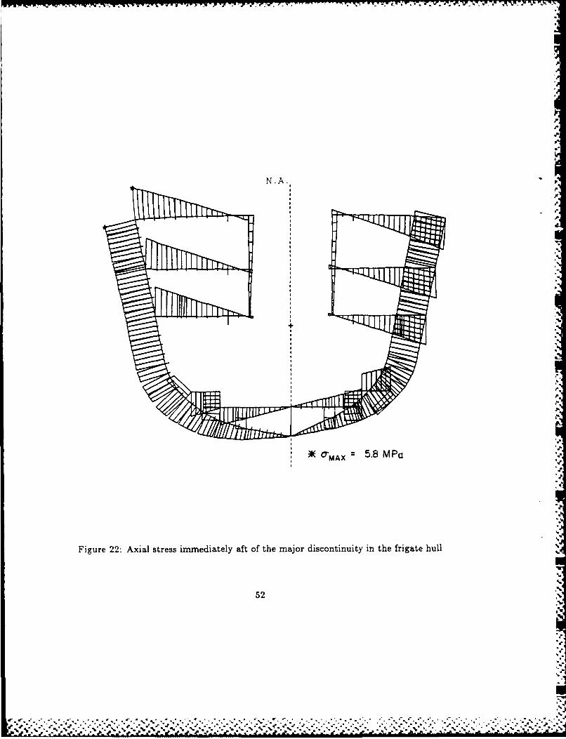
T-'YW! V - -J-, 1' J - -. . J . -w* . -~ ~~ ~~~ ~
'p
!
F
N.A.
A O-MA x = 5.8 MPa
Figure 22: Axial stress immediately aft of the major discontinuity in the frigate hull
52.
IN

.4.
N. A.
. %
)K CMAX 7 4 MWa
Figure 23: Axial stress immediately foreward of the major discontinuity in the frigate bull.
53 ~ ~x

* + CENTROID0 SHEAR CENTER)K T'MAX =5.4 MPa
* Figure 24: Shear stress distribution from a traditional analysis for a cross-section of thefrigate hull.
54
% V % N"

+ CENTROID19 SHEAR CENTER)K TMAX =3.8 MP(3
Figure 25: Shear stress distribution from the warping based methods for a cross-section of
the frigate hull.
55

EI ".' - G- --" m(-) (197)
where m represents the external couple per unit length along the beam. Defining the non- ,dimensional parameter, k, as, :.
k 1 E,,, (198)
equation (197) can be written, '
T2,,k E, ,,,-
The fundamental solution of this linear, inhomogeneous differential equation is obtained by "assuming a solution form €=er' and solving the characteristic equation for the roots r. "oThis leads to a general solution of the form, kzk
O(X) = C1 + C2(X) + C3 sinh -- + C4 cosh - + P(X) (200)
The coefficients of the solution can be determined from the bounda-ry conditions of the ,problem once a particular solution has been established for the given load case. Somecommon forms include,
concentrated load:"
M () = 0 (201).-,RP(X) = 0 (202) "
uniformly distributed load: r
m(X) =PO (203)
2Fk~x .."
P(X) =-Po21Eiw (204) :.
sinusoidal distribution:re(x) = Asin T (205).''
P~x) = At' sin _P()=Ei,,r2C7r2 + k2) (206).'"
.
Four boundary conditions are required, two per beam end, to establish the completesolution. These conditions can be in the form of kinematic or statical constraints. Some
56
7' z.
Appedix - N teson te Diferntia Equtio
The lasica diferntil euaton f wrpig trsin i a hinwaled eamis ive as

common conditions include, .clamped pend:'" ..
€ ' = 0 ( 2 0 7 )"free to wapbut not rotate: ".M 0 (208)
free end:"' ' ' "M, -- T = 0 (209)
Other boundary conditions and combinations are possible, such as linear relations between "5.-"statical and kinematic variables to reflect elastic support conditions. Reference 12 provides '"--a very complete presentation of the various load and boundary conditions.
It is instructive to consider the influence of the parameter k, which characterizes the ": .,elastic properties of the thin-walled beam. As an example, consider the axial stress distri--.bution for a clamped-free beam under a concentrated torsional end moment. In that case,.the complete solution of the differential equation (199) is given as, ...
T [x z+ I tanh k(cosh -T - 1) - I sinh kx(210)'-.-"
and hence, from the development of Section 3, the axial warping stress distribution is given
by, """'0k S - tanh k cosh )xs) (211)
Plotting the non-dimensionalized axial stress then gives a description of the attenuation of
that stress with length. This has been done in Figure A for various values of the parameterk. It can be seenst t the stress decays inene o th near fashion for this particular case.The higher the value of k, the more localized is the area influenced by the bimoment stressfield. In the limiting case of k = oo, the stress is completely concentrated at the restraint.Although the decay characteristics of the axial stress are a function of the load and boundary
conditions, this trend is universal."-' '-The value of k depends mainly on three characteristics of the beam: thickness, length,.','zand geometric configuration. It can readily be shown that k decreases with decreasing thick-ness by consideration of the St-Venant and warping stiffness dependence on that variable.Also evident is the importance of the overall beam length; again, in the limiting case ofan infinitely long beam, the warping stresses become completely localized. Not as evidentis the configurational dependence, and it is difficult to estimate a priori the ratio of theSt-Venant and warping torsional rigidities for complex geometries. .
Despite the fact that typical warship hulls are quite cellular and hence have large St-Venant torsional rigidities, the k values in the regions of large deck openings can be quite
57 " "
% ro %
an infinitely" long" beam, the°°warping stresses become" completely localized. Not as evident" I"
is t it-isdifficult to estiatea- pior the ratio ofth
St-Venant ~~~~ ~ ~ ~ !e and warin tosina riiiisfrcmpememtis
'e6 %

low. Assuming that the ends of the cut-out zone are essentially fixed against warpingbecause of their larger St-Venant stiffness, and using the length of the cut-out as a lengthparamenter, k values of 0.12 and 0.11 are obtained for the two major discontinuities inthe CPF hull. Warping restraints in these areas will therefore cause axial and secondarystresses of a non-localized nature.
According to the principle of St-Venant, stresses developed in a section through the al-plication of a balanced external load are localized, and dimirish rapidly away from the pointof load application. Such a principle should apply to the self-balancing force system of thebimoment distribution. However, because of the relatively slow decay of these axial stresssystems, particularily in thin-walled beams of open section, and the nature of the distortioncaused by these stresses, the application of the St-Venant principle to such structures is notvalid.
*8
58 ..
-I
% %* **~ ~ '. N ~ . . * -. % % .. I .,%. % % ~~ .%

LLI'
(.0s
2.~
0 . 0 2 , 0~ . 6 .21
X/0
Figure ~ ~ ~ ~ ~ ~ ~ ~ ~ ~ ~ ~ ~ ~ ~ ~ ~ ~ ~ , A :Ailsrs-itiuinfrvros ausi lme-reba ne
cocetrte 0ed omnt
59 uJ.

References
1. Kollbrunner, C.F., Hajdin, N.,'Warping Torsion of Thin-walled Beams of ClosedCross-section', Cement and Concrete Association Translation, Maisel, B.I., 1984.
2. Westin, H., 'Torsion of Non-Prismatic Beam Girders with Special Applications toOpen Ships', TRITA-SKP-1055, Div. of Naval Architecture, Royal Institute of Tech-nology, Stockholm, 1980.
3. Pittaluga, A., 'Recent Developments in the Theory of Thin-Walled Beams', Comput-ers and Structures, Vol. 9, 1978, pp. 69-79.
4. Pedersen, P.T. 'A Beam Model for the Torsional-Bending Response of Ship Hulls',Transactions, RINA, 1983.
5. 'Vibration and Strength Analysis of Ship Hulls and Appendages by Finite ElementMethods (HVAST)', User's manual, DREA contract OAD 3217048, Martec Ltd., NovaScotia, 1983.
6. Vernon, T.A., 'SCRAP, A Computer Program for Elastic Strength Analysis andEquivalent Beam Modelling of Ship Hulls', DREA Technical Memorandum 86/214,1986.
7. Pedersen, P.T., private communication
8. Principles of Naval Architecture, Society of Naval Architects and Marine Engineers,New York, N.Y., 1977.
9. Popov, E.P., Introduction to Mechanics of Solids, Prentice-Hall Inc., Englewood Cliffs,N.J., 1968.
10. Peery, D.J., Aircraft Structures, McGraw-Hill, N.Y., 1950.
11. Marshall, R.W., 'Shear Flow Distribution in Multi-Cell Girders', Computers andStructures, Vol. 4, 1974, pp. 307-325.
12. Vlasov, V.Z., Thin-Walled Elastic Beams, Israel Program for Scientific Translations,U.S. Department of Commerce, 1961.
13. Haslum, K., Tonnesen, A. 'Torsion of Thin-Walled Nonprismatic Beams', MeddelelseSK/M 22, Div. of Ship Structures, Technical University of Norway, Trondheim, 1971.
60
,.,

-~~~~W U WA~ .
14. Ulfvarson, A., 'Studies on the Structural Behaviour of Open Ships Under Torsion',Report E-46, Div. of Naval Architecture, Royal Institute of Technology, Stockholm,1975.
15. Kawai, T., 'The Application of Finite Element Methods to Ship Structures', Comput-ers and Structures, Vol. 3, 1973, pp. 1175-1194.
16. Gunnlauggsson, G.A., Pedersen, P.T., 'A Finite Element Formulation for Beams withThin Walled Cross-sections', Computers and Structures, Vol. 15, No. 6 1982, pp.691-699.
17. 'Conversion of TORSION.BAS Program to Fortran 77', DREA contract report, OSC-97707, Martec Ltd., Nova Scotia, 1985.
18. Lewis, F.M., 'The Inertia of Water Surrounding a Vibrating Ship', Trans. SNAME,Vol. 37, 1929.
19. 'Vibration and Strength Analysis Program (VAST), Version 4', DREA contract re-ports, Martec Ltd., Nova Scotia, 1986.
20. Vernon, T.A., 'SCRAP - Operational notes', DREA internal communication, 1985
21. Vernon, T.A., 'Comparisons Between Finite Element and Beam Theory Analyses ofThin-walled Beams in Torsion', DREA informal communication, 1986. "
22. Lloyds Register of Shipping, Rules and Regulations of the Classification of Ships, Part .•.
4, London, 1978.
.4.. -.
$+-% .1*°o?
61
V........
* .* ." ** . . .

Bibliography m
1. Kollbrunner, C.F., Basler, K., Torsion in Structures, Springer-Verlag, Berlin, 1969.
2. Pedersen, P.T. 'Torsional Response of Containerships', J. of Ship Research, Vol. 29,No. 3, 198-, pp. 194-205.
3. Hughes, O.F., Ship Structural Design, John Wiley, N.Y., 1983.
4. Vajravelu, P., 'Torsional Strength and Rigidity of 'Open' Ships', Shipping World andShip Builder, August, 1970.
5. Kawai, T., 'Studies on the Ultimate Strength Analysis of a Ship Structure by meansof a New Discrete Thin-Walled Beam Element', J. of Society of Naval Architecture of .-'
Japan, Vol. 150, 1982, pp. 381-388. ..-e.I...
6. Haslum, K., Tonnessen, A., 'An Analysis of Torsion in Ship Hulls', European Ship-building, No. 5/6, 1972, pp. 67-90.
7. Haslum, K., Pedersen, B., 'Torsional Response of a Ship in the Seaway with ParticularReference to an LNG Tanker', Norwegian Maritime Res., Vol. 1, No. 3, 1973.
'-
,°.'.
62
% %
... .. . . .. . .
:, ; . • , , -,, -, , . . , -o - -, ' , • , ; ,; .. • .. * * -. * ., - --.. -. ', . . " -' .; -. . --.- . '

UNLIMITED DISTRIBUTION
securityCaIEete
DOCUMENT CONTROL DATA - R & D, ui'lly clossiscat on of title. body of 4abtract and *ndexing annotation must be entered when the o rall document is cIen.ii edl
I ORIGINATING ACTIVITY 2s. DOCUMENT SECURITY CLASSIFICATION
Defence Research Establishment Atlantic Ucasfe2b, GROUP
3 DOCUMENT TITLE
Thin-Walled Beam Theories and Their Applications in the Torsional
Strength Analysis of Ship Hulls
4 DESCRIPTIVE NOTES (Type of report and incluse date%) Technical Memorandum
5 AUTHOR(S) (Last name, first name, middle initi )I
Vernon, Thomas, A., and Nadeau, Y.
6 DOCUMENT DATE 7a. TOTAL NO. OF PAGES 7b. NO. OF REFSJANUARY 19B7 7 2 22
Ba. PROJECT OR GRANT NO. 9a ORIGINATOR'S DOCUMENT NUMBER(SI
DREA TECHNICAL MEMORANDUM 87/202 %Z..
Bb. CONTRACT NO. 9b. OTHER DOCUMENT NO(S) (Any other nuw6vs that may beeuigned thits document)
10 DISTRIBUTION STATEMENT
UNLIMITED DISTRIBUTION
11 SUPPLEMENTARY NOTES 12. SPONSORING ACTIVITY dl
13 ABSTRACT- Unified developments of the St-Venant and warping-based thin-walled beam theories
and their application in the torsional analysis of ship structures are presented. Open cell,
closed cell and multi-cell configurations are treated. The warping-based torsional theory,
which accounts for out-of-plane displacements and displacement restraints, provides axial
stress distributions resulting from bimoments and in general offers improved predictions
of shear stress distribution in thin-walled beams over the St-Venant theory; however, the
use of that theory necessitates a more detailed cross-sectional property evaluation. The
generalization of the warping function to a displacement field independent of the twist is
discussed, as are several iterative methods of including warping shear deformations. The
application of the prismatic warping theory to the analysis of non-prismatic beams is dis-
cussed, and the flexuralltorsional beam method proposed by Pedersen is developed. This -"
method, in conjunction with a computer program to calculate the' required cross-sectional
properties, has been integrated into a general torsional stress analysis capability within N
Defence Research Establishment Atlantic (DREA). The DREA system, which can accountfor geometric discontinuities in a structure, has been developed as an alternative to finitePlement methods, and is evaluated here via comparison with detailed finite element analy-
ses for several prismatic beams with discontinuities,, The flexural-torsional model appears
to give representative behaviour only -or stect-fres which possess considerable transverse
rigidity. Finally,lhe beam theory is applied to the stress analysis of the hull of a frigate.
The shear and axial stresses predicted for the applied torsional load are quite low, despite
the existence of significant geometric discontinuities in the hull.
63
%.,-.,

Unclassifiedsecurlity Cassiffcaflton
KEY WORDS
Thin-walled beamsTorsionTorsional analysisShip structuresShip strengthShip hull
_ _
INSTRUCTIONS
1 ORIGINATING ACTIVITY Enter the name alnd addrems of the 9b. OTHER DOCUMENT NUMBER(S). If the document has beenorgazanron issuing the document. assi ied any other document numbers (either by the originator
or by the sponsor), ahlo enter this numberis).2x DOCUMENT SECURITY CLASSIFICATION Enter th)e overall
security classification of the document including special warning 10. DISTRIBUTION STATEMENT: Enter any limitations onerms whenever applicable, fufthe dissemination of the documeifnlt, other then those imposed
by securIty clasification, using standard statements suc as
2b. GROUP Enter security reclassification group number. The thee
poups are defined in Appendix M'of the DRB Security RAeglations. (1) Ouellfhed requesters may obtain copeies of thisdocu ment from their defence documentation centeir."
3. DOCUMENT TITLE: Enter the complete document title in allcaOital setters. Titles in all cases should be unclassified If a (2) "Announcement and dissemination of this documentsufficiently descriptive title cannot be selected without classifi- is not authorized without prior approval fromCtion, show title classification with the usual one-ceptal-letter originating activity."
abbreviation in parentheses immediately following the title.11. SUPPLEMENTARY NOTES Use for additional explanatory
4 DESCRIPTIVE NOTES, Enter the category of document, e.g. notas.tchnical report. technical note or technical latter. If approprt-ate, enter the type of document, e.g. interim, progress, 12. SPONSORING ACTIVITY Enter the name of the departmental
summary, annual or final. Give the inclusive dates when a project office or laboratory sponsoring the remech and
specific reporting period it covered. levelop nt. Include address.
5. AUTHOR(S): Enter the nameis) of aurhoris) as shown On or 13. ABSTRACT: Enter an abstract giving a brief end fatial
in the document. Enter last name. first namen, middle initial, summary of the document, even though it may also appear KIf military, show rank. The name of the principal author is an elsewhere in the body of the document itself. It is hihlyabsolute minimum requirement, desirable that the abstract of classified documents be unclassi-
fied, Each esreraph of the abstract hull end with en6 DOCUMENT DATE: Enter the dale (month, va) of indication of the security Classification of the Informsatlon
Establishment approval for publication of the document. i the paragraph (unlees the document Itself is unclassified)represented as ITS), IS). IC), (R) or (U).
7a. TOTAL NUMBER OF PAGES The total pog count should
follow normal pagination procedures. i.e.. enter the num bers The leigth of the abstract should be limited to 20 simle-spacadof paes containing information standard typeritten fines. 7 Inches long.
7t NUMBER OF REFERENCES Enter the total number of 14. KEY WORDS: Key words ae technically masilngtul teems or
references cited in the document. so phrases that characterize a document end could be helpfulin caaloging the document. Key worc should be slected so
Be PROJECT OR GRANT NUMBER: It appropriate, enter the that no security clasificatilon is required. Identifiers. such as.solicable resa.,rch and development project or ant number aqtp len moel designation. trade name, military protect code
under which the document was written, name. geographic location, may be used as key words but willbe followed by an indication of technical context.
8bt CONTRACT NUMBER It apipropriate. enter the applicablenuinber under which the document was written.
b ORIG NATOR'S DOCUMENT NUMBER(SI Enter the
r fl, l licument number by which the document will be
tenisi..rd tad controlled by the oiiginating activity. Thitnumber must be unique to this document.
64
L
ir ~ ' %,' 'r ee
t4.r" " r. -ow%' %i- if- r .. . .i .t;%. *; .x Z% :K V t-.: .r a ' p''' --...
,{_ ;" ." - o" ,* =" #'. ' ~~~~~~~~~~~~. . ".".'."..... . . .. . . .... . . '... '.".".-.... '.p . ." 5%d22 ".. % r %Y% , ".a ." a 2" , ' ' '

4
A
.i..
F
d
"I'
r..
I,..
A
Is-s.I,'.
Is,.,
I'