MENIFEE ELEMENTARY SCHOOL #14 - boibord.com€¦ · MENIFEE ELEMENTARY SCHOOL #14 ... Construction...
20
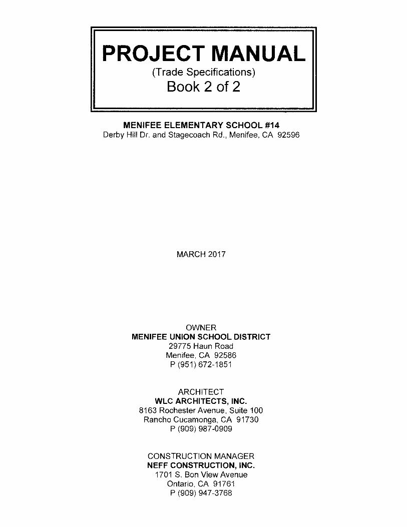
PROJECT MANUAL (Trade Specifications) Book 2 of 2 MENIFEE ELEMENTARY SCHOOL #14 Derby Hill Dr. and Stagecoach Rd., Menifee, CA 92596 MARCH 2017 OWNER MENIFEE UNION SCHOOL DISTRICT 29775 Haun Road Menifee, CA 92586 P (951) 672-1851 ARCHITECT WLC ARCHITECTS, INC. 8163 Rochester Avenue, Suite 100 Rancho Cucamonga, CA 91730 P (909) 987-0909 CONSTRUCTION MANAGER NEFF CONSTRUCTION, INC. 1701 S. Bon View Avenue Ontario, CA 91761 P (909) 947-3768
Transcript of MENIFEE ELEMENTARY SCHOOL #14 - boibord.com€¦ · MENIFEE ELEMENTARY SCHOOL #14 ... Construction...
PROJECT MANUAL(Trade Specifications)
Book 2 of 2
MENIFEE ELEMENTARY SCHOOL #14Derby Hill Dr. and Stagecoach Rd., Menifee, CA 92596
MARCH 2017
OWNERMENIFEE UNION SCHOOL DISTRICT
29775 Haun RoadMenifee, CA 92586
P (951) 672-1851
ARCHITECTWLC ARCHITECTS, INC.
8163 Rochester Avenue, Suite 100Rancho Cucamonga, CA 91730
P (909) 987-0909
CONSTRUCTION MANAGERNEFF CONSTRUCTION, INC.
1701 S. Bon View AvenueOntario, CA 91761P (909) 947-3768

PROJECT MANUALFOR
ELEMENTARY SCHOOL NO. 14
PROJECT 1513900
SEPTEMBER 2015
MENIFEE UNION SCHOOL DISTRICT
MENIFEE, CA 92584
WLC ARCHITECTS, INC.8163 ROCHESTER AVENUE, SUITE 100
RANCHO CUCAMONGA, CA 91730(909) 987-0909
StampJAMES P DiCAMILLO C15937ARCHIT CT D Aq
WLC Architects, Inc. o8163 Rochester Avenue, Suite 100 NO.CRancho Cucamonga, CA 91730 N 97Phone: (909) 987-0909 REN. IICifFax: (909) 980-9980
SCAO.A
DIVISION OF THE STATE ARCHITECTAPPROVALS
IDEN11FICATION STAMPDIV. OF THE STATE ARCHITECT
OFFICE OF REGULATION SERVICESStructural Safety a I wu
APPL i14 790Fire and Life Safety AC -ELS 5'
DATE I A17Access Compliance
Page 1 of 3

PROJECT MANUAL
FOR
ELEMENTARY SCHOOL NO. 14
PROJECT 1513900
DSA APPLICATION NO.
SEPTEMBER 2015
MENIFEE UNION SCHOOL DISTRICT
MENIFEE, CA 9254
WLC ARCHITECTS, INC.8163 ROCHESTER AVENUE, SUITE 100
RANCHO CUCAMONGA, CA 91730(909) 987-0909
StampPETER TRAN, SE S4628STRUCTURAL ENGINEER 0 FES
K.B. Leung and Associates, Inc,9320 Baseline Road, Suite DAlta Loma, CA 91701-5829 0-4628 2Phone: (909) 944-0029 E -lo-Fax: (909) 944-7983
--- CATOW
T M U C59118 StampVIL GI
Epic Engineers, Inc.101 East Redlands Boulevard, Suite 146Redlands, CA 92373-4723Phone: (909) 792-5969 No.Fax: (909) 792-8869 Exp.
PORNDHEP KALAMBAHETI M29219 StampMECHANICAL ENGINEER
IDS Mechanical Engineers, Inc.1 Peters Canyon Road, Suite 150Irvine, CA 92606-1748Phone: (949) 387-8500 0. M-292,9
Page 2 of 3

PROJECT MANUAL
FOR
ELEMENTARY SCHOOL NO. 14
PROJECT 1513900
DSA APPLICATION NO. -0 Y - Qi01SEPTEMBER 2015
MENIFEE UNION SCHOOL DSTRICT
MENIFEE, CA 92584
WLC ARCHITECTS, INC.8163 ROCHESTER AVENUE, SUITE 100
RANCHO CUCAMONGA, CA 91730(909) 987-0909
IRWAN YOWA TO 17238 StampELECTRICAL ENGINEER
YO 4Yowanto Engineering, Inc.2705 N. Towne Avenue, #CPomona, CA 91767 NolE17238P: (626) 252-5150 xp. 61
OUGLAS Dr3GS 3191 StampLANDSCAPE ARCHITECT
Integrated Design Group, LLP OSCAp
1308 Monte Vista Avenue, Suite 6 SGGS CUpland, CA 91786-8224Phone: (909) 946-6400 -- IGNATURE
RENEWAL DAT~*
DATE
OF CAL
Page 3 of 3

SECTION 03 11 00
CONCRETE FORMWORK
1. PART 1 GENERAL
1.1 SECTION INCLUDES
A. Formwork for cast-in-place concrete, with shoring, bracing, and anchorage.
B. Openings for other affected work.
C. Form accessories.
D. Stripping forms.
1.2 REFERENCES
A. CBC - California Building Code, (CCR) California Code of Regulations, Title 24, Part 2, Chapter 19A.
B. ACI 301 - Specifications for Structural Concrete for Buildings.
C. PS 1-95 - Construction and Industrial Plywood.
1.3 SYSTEM DESCRIPTION
A. Design, engineer, and construct formwork, shoring, and bracing to meet design and code requirements, sothat resultant concrete conforms to required shapes, lines, and dimensions.
1.4 QUALITY ASSURANCE
A. Construct and erect concrete formwork in accordance with ACI 301.
1.5 REGULATORY REQUIREMENTS
A. Conform to CBC - California Building Code, (CCR) California Code of Regulations, Title 24, Part 2.
2. PART 2 PRODUCTS
2.1 FORM MATERIALS
A. Plywood: PS1-95, BB Plyform grade, Class I, Exterior classification.
B. Lumber: Douglas Fir species; construction grade; with grade stamp clearly visible.
2.2 FORMWORK ACCESSORIES
A. Form Ties: Snap-off metal of adjustable length; cone type; 1 inch break back dimension; free of defects thatwill leave holes no larger than one inch diameter in concrete surface.
B. Form Release Agent: Colorless material which will not stain concrete, absorb moisture, or impair naturalbonding or color characteristics of coating intended for use on concrete.
C. Fillets for Chamfered Corners: Wood strips type; 3/4 x 3/4 inch size; maximum possible lengths.
D. Dovetail Anchor Slots: Minimum 22 gage galvanized steel; foam filled; release tape sealed slots; bent tabanchors; securable to concrete formwork; manufactured by Heckmann Building Products Co.,www.heckmannbuildingprods.com.
E. Flashing Reglets: 26 gage thick galvanized steel; longest possible lengths; release tape sealed slots; withalignment splines for joints; securable to concrete formwork; Type CO reglet manufactured by Fry Regletwww.fryreglet.com.
WLC/1513900 CONCRETE FORMWORK 03 11 00
REV, 09104

F. Nails, Spikes, Lag Bolts, Through Bolts, Anchorages: Sized as required; of strength and character tomaintain formwork in place while placing concrete.
3. PART 3 EXECUTION
3.1 INSPECTION
A. Verify lines, levels, and measurements before proceeding with formwork.
3.2 PREPARATION
A. Obtain Architect's approval for use of earth forms for footings.
B. Minimize form joints. Symmetrically align joints and make watertight to prevent leakage of mortar.
C. Arrange and assemble formwork to permit stripping, so that concrete is not damaged during its removal.
D. Arrange forms to allow stripping without removal of principal shores, where required to remain in place.
3.3 ERECTION
A. Erect formwork, shoring and bracing to achieve design requirements, in accordance with requirements ofACI 301.
B. Provide bracing to ensure stability of formwork Strengthen formwork liable to be overstressed byconstruction loads.
C. Obtain approval before framing openings in structural members which are not indicated on Drawings.
D. Do not displace or damage vapor barrier placed by Section 03 30 00.
E. Construct formwork to maintain tolerances in accordance with ACI 301.
3.4 APPLICATION OF FORM RELEASE AGENT
A. Apply form release agent on formwork in accordance with manufacturer's instructions. Apply prior to placingreinforcing steel, anchoring devices, and embedded items.
B. Do not apply form release agent where concrete surfaces are scheduled to receive applied coverings whichmay be affected by agent. Soak contact surfaces of untreated forms with clean water. Keep surfaces wetprior to placing concrete.
3.5 INSERTS, EMBEDDED PARTS, AND OPENINGS
A. Provide formed openings where required for work embedded in or passing through concrete.
B. Coordinate work of other Sections in forming and setting openings, slots, recesses, chases, sleeves, bolts,anchors, and other inserts.
C. Install accessories in accordance with manufacturer's instructions, level and plumb. Ensure items are notdisturbed during concrete placement.
3.6 FORM REMOVAL
A. Do not remove forms and bracing until concrete has sufficient strength to support its own weight andimposed loads.
B. Do not damage concrete surfaces during form removal.
C. Store reusable forms for exposed architectural concrete to prevent damage to contact surfaces.
WLC/1513900 CONCRETE FORMWORK 03 11 00(2)
REV 09104
3.7 CLEANING
A. Clean forms to remove foreign matter as erection proceeds.
8. Ensure that water and debris drain to exterior through clean-out ports.
3.8 EARTH FORMS
A. Construct wood edge strips at top sides of excavations as indicated on drawings.
B. Provide forms for footings and foundation walls wherever concrete cannot be placed against solid earth.
C. Remove loose dirt and debris from form area prior to concrete placement.
D. Concrete for foundations may be placed directly into neat excavations provided the foundation trench wallsare stable as determined by the Architect (Structural Engineer) subject to the approval of The Division ofthe State Architect.
E. When earth formed foundations are used, the minimum formwork shown on the drawings is mandatory toinsure clean excavations prior to and during concrete placement.
F. Provide 3-1/2 inch high starter wall for all concrete and masonry walls below grade.
END OF SECTION
WLC/1 513900 CONCRETE FORMWORK 03 11 00(3)
REV. 09/04

SECTION 03 20 00
CONCRETE REINFORCING
1. PART 1 GENERAL
1.1 SECTION INCLUDES
A. Reinforcing steel bars, welded steel wire fabric fabricated steel bar or rod mats for cast-in-place concrete.
B. Support chairs, bolsters, bar supports, and spacers, for supporting reinforcement.
1.2 REFERENCES
A. CBC - California Building Code, (CCR) California Code of Regulations, Title 24, Part 2, Chapter 19A(ACI 318).
B. ACI 301 - Specifications for Structural Concrete for Buildings.
C. ACI 315 (SP-66) - Details and Detailing of Concrete Reinforcement.
D. ACI 318 - Building Code Requirements for Reinforced Concrete.
E. ASTM A82 - Cold Drawn Steel Wire for Concrete Reinforcement.
F. ASTM Al 85 - Welded Steel Wire Fabric for Concrete Reinforcement.
G. ASTM A615 - Deformed and Plain Billet-Steel Bars for Concrete Reinforcement.
H. ASTM A706 - Standard Specification for Low Alloy Steel Deformed Bars for Concrete Reinforcement.
1. ASTM C1 116 - Specification for Fiber-Reinforced Concrete and Shotcrete.
J. AWS D1 .4 - Structural Welding Code Reinforcing Steel,
K. CRSI - Manual of Practice.
L. CRSI - Placing Reinforcing Bars.
1,3 QUALITY ASSURANCE
A, Perform concrete reinforcement work in accordance with CRSI Manual of Standard Practice.
B. Conform to ACI 301 and ACI 315 (SP-66).
C. Conform to CBC California Building Code, (CCR) California Code of Regulations, Title 24, Part 2.
1,4 CERTIFICATES
A. Submit mill test certificates of supplied concrete reinforcing, indicating physical and chemical analysis.
2. PART 2 PRODUCTS
2.1 MATERIALS
A. Reinforcing Steel: ASTM A615, Grade 40 for No. 4 bars and smaller, Grade 60 for No. 5 bars and larger.Billet-steel deformed bars, uncoated finish.
B. Welded Reinforcement: ASTM A706, Grade 60, deformed bars, unfinished.
C. Welded Steel Wire Fabric ASTM A185 plain type; coiled rolls; uncoated finish.
WLC/1 513900 CONCRETE REINFORCING 03 20 00(1)
REV 03115

D. Steel Wire: ASTM A82, plain, cold drawn steel.
2.2 ACCESSORY MATERIALS
A. Tie Wire: Minimum 16 gage annealed type.
B. Chairs, Bolsters, Bar Supports, Spacers: Sized and shaped forstrength and support of reinforcement duringinstallation and placement of concrete including load bearing pad on bottom to prevent vapor barrierpuncture.
2.3 FABRICATION
A. Fabricate in accordance with ACl 315 (SP-66), providing concrete cover specified in Section 03 30 00.
B. Locate reinforcing splices not indicated on Drawings at points of minimum stress.
C. Weld reinforcing bars in accordance with AWS D1.4.
3. PART 3 EXECUTION
3.1 INSTALLATION
A. Before placing concrete, clean reinforcement of foreign particles or coatings.
B. Place, support, and secure reinforcement against displacement. Do not deviate from alignment ormeasurement.
C. Mix fibrous reinforcement into concrete material according to Section 03 30 00.
D. Do not displace or damage vapor barrier required by Section 03 30 00.
3.2 FIELD QUALITY CONTROL
A. Field inspection and testing will be performed under provisions of Section 01 45 29 and as required by theDivision of the State Architect and District Inspector.
END OF SECTION
WLC/1 513900 CONCRETE REINFORCING 03 20 00(2)
REV 03/15

SECTION 03 30 00
CAST-IN-PLACE CONCRETE
1. PART 1 GENERAL
1.1 SECTION INCLUDES
A. Cast-in-place concrete foundation walls, and footings.
B. Floors and slabs on vapor barrier.
C. Control, expansion, and contraction joint devices associated with concrete work.
D. Curing and sealing compound.
E. Retaining walls, utility slabs.
F. Equipment pads, Thrust blocks, Light pole bases, Flag pole bases.
1.2 REFERENCES
A. The 2010 Americans with Disabilities Act (ADA) Standards for Accessible Design.
B. CBC - California Building Code, (CCR) California Code of Regulations Title 24, Part 2, Chapter 19A.
C. CBC - California Building Code, (CCR) California Code of Regulations, Title 24, Part 2, California StateAccessibility Standards.
D. ACI 301 - Specifications for Structural Concrete for Buildings.
E. ACI 302.1 R - Guide for Concrete Floor and Slab Construction.
F. ACt 305R - Hot Weather Concreting.
G. ACI 306.1 - Standard Specification for Cold Weather Concreting.
H. ACI 318 - Building Code Requirements for Concrete.
L ASTM C33 - Concrete Aggregates.
J. ASTM C94 - Ready-Mixed Concrete.
K. ASTM C109 - Standard Test Method for Compressive Strength of Hydraulic Cement Mortars
L. ASTM C150 - Portland Cement.
M. ASTM C260 - Air-Entraining Admixtures for Concrete.
N. ASTM C289 - Potential Reactivity of Aggregate.
O. ASTM C309 - Liquid Membrane Forming Compound.
P. ASTM C330 - Lightweight Aggregates for Structural Concrete.
Q. ASTM C494 - Standard Specifications for Chemical Admixtures for Concrete.
WLC/1 513900 CAST-IN-PLACE CONCRETE 03 30 00(1)
REV 03115

R. ASTM C567 - Unit Weight of Structural Lightweight Concrete.
S. ASTM C618- Standard Specification for Coal Fly Ash and Raw or Calcined Natural Pozzolan for Use as aMineral Admixture for Concrete.
T. ASTM C932 - Surface-Applied Bonding Agents.
U. ASTM C1315 - Liquid Membrane-Forming Compounds Having Special Properties for Curing and SealingConcrete.
V. ATM C1602 - Standard Specification for Mixing Water Used in the Production of Hydraulic CementConcrete,
W. ASTM D226 - Asphalt Saturated Organic Felt used in Roofing and Waterproofing.
X. ASTM D1751 - Preformed Expansion Joint Filler for Concrete Paving and Structural Construction.
Y. ASTM E96 - Standard Test Methods for Water Vapor Transmission of Materials.
Z. ASTM E154 - Standard Test Methods for Water Vapor Retardants used in Contact with Earth Under
Concrete Slabs, on Walls, or as Ground Cover.
AA. ASTM E1643 - Installation of Water Vapor Retarders used in Contact with Earth or Granular Fill UnderConcrete Slab.
BB. ASTM E1155 - Determining Floor Flatness and Levelness Using the F-Number System.
CC. ASTM E1745 - Standard Specifications for Plastic Water Vapor Retarders Used in Contact with Soil Or
Granular Fill Under Concrete Slabs.
DD. ASTM F1249 - Standard Test Method for Water Vapor Transmission Rate Through Plastic Film andSheeting Using a Modulated Infrared Sensor.
EE. ASTM F1869 - Standard Test Method for Measuring Moisture Vapor Emission Rate of Concrete SubfloorUsing Anhydrous Calcium Chloride.
FF. National Ready Mix Concrete Association - Plant Certification Program.
GG, Stormwater Best Management Practice Handbook (BMP Handbook), Construction Edition, as published bythe California Storm Water Quality Association.
1.3 QUALITY ASSURANCE
A. Perform work in accordance with ACI 301.
B. Obtain materials from same source throughout the Work.
1.4 QUALIFICATIONS
A. Manufacturer: Manufacturer of ready-mix concrete products complying with ASTM C94 requirements for
production facilities and equipment. Certified according to National Ready Mix Concrete Associates Plant
Certification Program.
WLC/1 513900 CAST-IN-PLACE CONCRETE 03 30 00(2)
REV. 03/15

1.5 DESIGN MIX
A. Submit design mix for each class of concrete, prepared by a California Registered Civil Engineer, to TestingLaboratory and Architect for review.
1.6 REGULATORY REQUIREMENTS
A. Conform to CBC - California Building Code, (CCR) California Code of Regulations, Title 24, Part 2.
B. Conform to CBC - California Building Code, (CCR) California Code of Regulations, Title 24, Part 2, and the2010 ADA Standards for Accessible Design for access requirements for individuals with disabilities,
1.7 SUBMITTALS
A. Submit product data and manufacturer's instructions under provisions of Section 01 33 00.
1.8 PRE-INSTALLATION CONFERENCE
A. Convene a conference two weeks prior to commencing placement of floor slab work of this section, underprovisions of Section 01 31 00.
B. Require attendance of parties directly affecting the work of this Section.
C. Agenda:
1. Placement of subgrade beneath floor slab.
2. Testing of subgrade beneath floor slab.
3. Delivery and placement of concrete.
4. Testing and inspection procedures for concrete.
5. Submittal of mix design for concrete.
6. Hot and cold weather concreting procedures.
7. Vapor barrier location and installation.
8. Placement of control and expansion joints.
9. Steel reinforcement installation.
10. Installation of inserts and embedded items.
11. Finishes and finishing,
12. Forming and form removal limitations.
13. Floor slab flatness and levelness requirements.
14. Curing process and procedures.
15. Protection of finished floor slabs.
16. Floor slab joint and crack repair.
WLC/1513900 CAST-IN-PLACE CONCRETE 03 30 00(3)
REV, 03/15

17. Moisture vapor transmission testing.
1,9 WARRANTY
A. Provide fifteen year warranty from curing, hardening and vapor barrier compound manufacturer under
provisions of Section 01 77 00.
B. Warranty: Include coverage for removal and replacement of finish floor materials that delaminate from
interior floor slabs due to moisture migration and excessive vapor emissions or due to presence of
efflorescence and alkali contaminates.
1. Subfloor Moisture Conditions: Moisture emission rate of no more than 3 lb/1 000 sq. ft.124 hours when
tested by Quantitive Anhydrous Calcium Chloride Test, ASTM F1 869, with subfloor temperature not
less than 65 degrees F.
2. Subfloor Alkalinity Conditions: A pH range of between 5 to 9 when subfloor is wetted with potable
water and pHdrion paper is applied.
3. Warranty to be supported by $1,000,000.00 product liability insurance policy issued directly to the
Owner.
1.10 ENVIRONMENTAL REQUIREMENTS
A. Provide concrete curing, finishing, and waste management techniques as defined in Section 4 of the Storm
Water Best Management Practice Handbook, (BMP Handbook) Construction Edition.
2. PART 2 PRODUCTS
2.1 FORMWORK
A. As specified in Section 03 11 00.
2.2 REINFORCEMENT
A. Reinforcing steel as specified in Section 03 20 00.
2,3 CONCRETE MATERIALS
A. Cement: ASTM C150, Type I or Type II Portland type; low alkali; grey color-
B. Fine and Coarse Aggregates Normal Weight Concrete: ASTM C33, non reactive when tested in accordance
with ASTM C289 and Appendix X-1 of ASTM C33.
C. Fine and Coarse Aggregate, Light Weight Concrete: ASTM C330.
D. Water: ASTM C1602, clean and not detrimental to concrete.
2.4 ADMIXTURES
A. Fly Ash: ASTM C618, Class F.
B. Water Reducing Admixture: ASTM C494, Type A.
C. Calcium chloride, or any other admixtures not allowable.
WLC/1 513900 CAST-IN-PLACE CONCRETE 03 30 00(4)
REV 03/15

2.5 VAPOR BARRIER
A. Material: 15 mil thick polyethylene film meeting the requirements of ASTM E1745, Class A, with a maximumpermeance of 0.01 perms in accordance with ASTM E96/E154, Section ?, and a Water Vapor TransmissionRate (WVTR) of less than 0.0037 when tested according to ASTM F1249.
B. Accessories:
1. Minimum 4 inch wide polyethylene tape with pressure sensitive adhesive.
2. PVC termination bar with pre-drilled holes.
3. All accessories provided by vapor barrier manufacturer,
C. Manufacturers:
1. Fortifiber Building Products, www.fortifiber.com.
2. Poly-America, www.yellowguard.com.
3. Reef Industries, www.reefindustries.com.
4. Stego Industries, www.stegoindustries.com.
5. Substitutions: Under Provisions of Section 01 25 13.
2.6 ACCESSORIES
A. Underlayment: ASTM D226, Type I (No. 15) asphalt saturated roofing felt.
B. Bonding Agent: ASTM C932; Weld-Crete as manufactured by Larsen Products Corp.,www.larsenproducts.com.
C. Non-shrink Grout: Premixed compound consisting of non-metallic aggregate, cement, water reducing andplasticizing agents; capable of developing minimum compressive strength of 7000 psi in 28 days.
D. Joint Filler ASTM 01751, 1/2 inch thick.
E. Sand Fill: Manufactured "crusher run" sand free of silt, clay, loam, friable or soluble materials or organicmatters, all passing the No. 4 sieve and only 5 percent passing the No. 200 sieve.
F. Curing, Hardening and Vapor Barrier Compound: ASTM C1 315, Type 1, Class A and ASTM C309, Type 1,Class A, with maximum volatile organic compound (VOC) content rating as required to suit regulatoryrequirements. Material to have no less than 34 percent penetrating solids, have no visible sheen and becompatible with floor finish materials and overlayments. Provide the following:
1. PMC 3300 Penetrating Sealer manufactured by Curranseal, www.curranseal.com.
G. Sealing Compound: Ashford Formula manufactured by Curecrete Distribution, Inc.,www.ashfordformula.com.
H. Slip Resistant Aggregate: 95 percent minimum fused homogeneous aluminum oxide.
WLC/1 513900 CAST-IN-PLACE CONCRETE 03 30 00(5)
REV. 0315

1. Chemical Concrete Stain: Penetrating reactive concrete stain and clear sealer of color selected by Architect.
Subject to compliance with requirements provide one of the following:
1. Blush-Tone Acid Stain as manufactured by Rafco Products Co., www.brickform.com.
2. Lithochrome Chemstain as manufactured by L.M. Scofield Co., wvw.scofield.com.
3. ChlorStain as manufactured by Super Stone, Inc., www.superstone.com.
4. Patina Stain System as manufactured by the Symons Corporation, wwwsymons.com.
5. SGS Concrete Stain as manufactured by Solomon Grind Chemical Services, www.solomoncolors.com.
J. Concrete Floor Slab, Saw Cut, Joint, Crack, Repair Material: Cement-based, polymer-modified product that
can be feathered at edges to match adjacent floor elevations. Compressive strength not less than 4,200
psi at 28 days when tested according to ASTM C109. Equivalent to ARDEX SD-F Feather Finish,
www.ardex.com. Epoxy base to be equivalent to Simpson ET-22 semi-rigid epoxy, www.strongtie.com.
K. Substitutions: Under provisions of Section 01 25 13.
2.7 CONCRETE MIX
A. Mix concrete in accordance with ASTM C94 ACI 318, Section 5.3.
B. Footings: Proportion normal-weight concrete mixture as follows:
1. Minimum Compressive Strength: 3,000 psi at 28 days.
2. Maximum Water-Cement Materials Ratio: 0.50.
3. Aggregate Size: 1 inch maximum.
4. Slump Limit: 4 inch minimum, 6 inch maximum.
5. Fly Ash: Maximum 25 percent by weight.
C. Foundation Walls: Proportion normal-weight concrete mixture as follows:
1. Minimum Compressive Strength: 3,000 psi at 28 days.
2. Maximum Water-Cement Materials Ratio: 0.50.
3. Aggregate Size: 1 inch maximum.
4. Slump Limit: 4 inch minimum, 6 inch maximum,
5. Fly Ash: Maximum 25 percent by weight.
D. Slabs-On-Grade: Proportion normal-weight concrete mixture as follows:
1. Minimum Compressive Strength: 4,000 psi at 28 days.
2. Minimum Cement Materials Content: 540 lb./cu. yd.
3. Maximum Water-Cement Materials Ratio: 0,45.
WLC/1 513900 CAST-IN-PLACE CONCRETE 033000(6)
REV 03/15

4. Aggregate Size: 1 inch maximum.
5. Slump Limit: 3 inch minimum, 5 inch maximum.
6. Fly Ash: Maximum 25 percent by weight.
E. Building Walls: Proportion normal weight concrete mixture as follows:
1. Minimum Compressive Strength: 3,000 psi at 28 days.
2. Maximum Water-Cement Materials Ratio: 0.60.
3. Aggregate Size: 1 inch maximum.
4. Slump Limit: 4 inch minimum, 6 inch maximum.
5. Fly Ash: Maximum 25 percent by weight.
3. PART 3 EXECUTION
3.1 INSPECTION
A. Verify anchors, seats, plates, reinforcement, and other items to be cast into concrete are accurately placed,held securely, and will not cause difficulty in placing concrete.
3.2 PREPARATION
A. At locations where new concrete is dowelled to existing work, drill holes in existing concrete, insert steeldowels, and pack solid with non-shrink grout.
B. Place 2 inch thick sand fill over subgrade.
C. Compact sand fill as specified in Section 31 20 00.
D. Install underlayment over wood subfloor. Lap joints 6 inches. Fasten in place.
3.3 VAPOR BARRIER
A. Install vapor barrier in compliance with ASTM El 643 under interior slabs over sand subgrade.
B. Install vapor barrier to exterior surface of below grade building foundation walls and grade beams. Seal tovertical surface of foundation wall with pressure sensitive tape and termination bar at an elevation consistentwith the top of the adjacent finish grade.
C. Lay vapor barrier with long dimension parallel with long dimension of space.
D. Lap vapor barrier over footing and seal to vertical surface of interior foundation wall with pressure sensitivetape and termination bar at an elevation consistent with the top of the slab.
E. Overlap all joints in vapor barrier 6 inches and seal with tape.
F. Seal all pipe penetrations of vapor barrier with pipe boot fabricated from vapor barrier material and tape.
G. Repair damaged areas with vapor barrier, overlapping damaged area by 6 inches and taping all four sides.
WLC/1 513900 CAST-IN-PLACE CONCRETE 03 30 00(7)
REV. 03/15

3.4 PLACING CONCRETE
A. Notify Architect minimum 24 hours prior to commencement of concreting operations.
B. Place concrete in accordance with ACl 301,
C. Hot Weather Placement: ACI 305R.
1 Maintain concrete temperature below 90 deg F at time of placement. Chilled mixing water or chopped
ice may be used to control temperature, provided water equivalent of ice is calculated to total amount
of mixing water.
2. Fog-spray forms, steel reinforcement, and subgrade just before placing concrete in hot weather. Keep
subgrade uniformly moist without standing water, soft spots, or dry areas.
D. Cold Weather Placement: ACI 306.1.
1. When average high and low temperature is expected to fall below 40 deg F for three successive days,maintain delivered concrete mixture temperature within the temperature range required by ACI 306.1
E. Ensure reinforcement, inserts, embedded parts and formed joints are not disturbed during concrete
placement.
F. Do not disturb or damage vapor barrier while placing concrete. Repair damage as required to maintain
integrity of barrier.
G. Place concrete continuously between predetermined construction and control joints. Do not break or
interrupt successive pours such that cold joints occur.
H. Place interior floor slabs on fill in a strip sequence pattern.
L Excessive honeycomb or embedded debris in concrete is not acceptable.
3.5 JOINTS
A. Saw cut control joints at an optimum time after finishing. Use 3/16 inch thick blade, cutting 1/3 into depth
of slab thickness.
B. Provide control joints at 15 feet on center unless otherwise indicated.
C. Separate slabs from vertical surfaces with joint filler. Extend joint filler from bottom of slab to within 1/4 inch
of finished slab surface.
3.6 FLOOR SLAB JOINT FILLING AND CRACK REPAIR
A. Prepare, clean, and install joint repair material according to manufacturer's written instructions.
B. Defer joint filling and crack repair until concrete has aged a minimum of 60 days.
C_ Remove dirt, debris, saw cuttings, curing compounds, and sealers from joints; leave contact faces of joint
clean and dry.
D. Mechanically V-groove as necessary all saw cuts, joints and cracks, to a minimum width of 1/4 inch and a
minimum depth of 5/8 inch.
E. Fill bottom of joint to a depth of at least 3/16 inch with semi-rigid epoxy.
WLC/1 513900 CAST-IN-PLACE CONCRETE 03 30 00(8)
REV, 03/15

F. Place silica sand over epoxy filler.
G. Fill all saw cuts, joints, and cracks with cement based joint repair material to top of concrete surface.
H. Steel trowel edges of joint repair material to a feather edge to match adjacent floor elevation.
I. Apply curing, hardening and vapor barrier compound over repaired joints, saw cuts and cracks.
3.7 FINISHING SLABS
A. Uniformly spread, screed and consolidate concrete. Do not spread concrete by vibration.
B. Float Finish: Float with hand float or with a powered disc float. High spots to be cut down and low spots tobe filled. Use as preparation for further finishing.
C. Scratched Finish: Mechanically float surfaces. Roughen with stiff brushes before final set. Use for quarrytile ceramic tile with full bed setting systems and where indicated.
D. Troweled Finish: After floating, steel trowel to smooth, mark free surface. Use for exposed floors and slabsto receive carpeting resilient flooring and where indicated.
E. Fine Broom Finish: After floating and while the surface is still plastic, provide a fine textured finish bydrawing a fine fiber bristle broom uniformly over the surface in one direction only. Use for exposed floorsand slabs and for floors and slabs to receive ceramic tile quarry tile using the thin set setting method andwhere indicated.
3.8 SLAB TOLERANCES
A. Maintain slab tolerance as defined in ACI 302.1R of (SOV) F,35 and FL25 and (MLV) FF24 and FL17 asmeasured by ASTM E1155 for slabs on grade.
B. Correct the slab surface if the actual F,/FL number for the floor installation measures less than required.
C. After correction of slab surface to specified tolerance, apply curing, hardening and vapor barrier overcorrected surface.
D. In areas of floor drains, maintain floor levels at the walls and slope surface uniformly to drains at 1/8 inchper foot.
3.9 CURING
A. Apply curing, hardening and vapor barrier compound on all floor slabs that are not exposed and indicatedto be sealed.
B. Cure concrete surfaces in accordance with ACI 301.
C. Spray apply curing, hardening and vapor barrier compound on finished slab surfaces located below grade,at grade, and above grade in two "wet on wet" flood coats at the total rate of 200 sq. ft./gallon in accordancewith manufacturers instructions.
D. Application of compound shall be by a trained applicator acceptable to compound manufacturer.
E. After application of curing, hardening, and vapor barrier compound, moist cure concrete using the followingmethod:
1. Spraying: Fog spray clean, potable water over floor slab areas and maintain moist for 10 days.
WLC/1 513900 CAST-IN-PLACE CONCRETE 03 30 00(9)
REV. 03115
Laraine
Highlight
Laraine
Highlight

2. Polyethylene Film: Spread over floor slab areas, lap edges and sides, maintain in place for 10 days.
3.10 SEALING
A. Apply sealing compound on finished floor slab surfaces that are not to receive a finished floor covering and
are indicated to be exposed and sealed.
B. Apply sealing compound immediately following finishing operation.
C. Apply sealing compound in sufficient quantities to keep entire surface wet for a minimum of 30 minutes.
D. Lightly mist surface with water as compound is absorbed into surface.
E. Flush surface with water and squeegee surface free of excess compound.
F. Burnish final concrete surface with propane burnisher.
3.11 PATCHING
A. Notify Architect immediately upon removal of forms to determine areas that will require patching.
B. Surface defects shall include color and texture irregularities, stains, cracks, spalls, air bubbles,
honeycombs, rock pockets, fins and other projections and discolorations in the surface that cannot be
removed by cleaning.
C. Patch imperfections in accordance with ACI 301.
3.12 DEFECTIVE CONCRETE
A. Modify or replace concrete not conforming to required levels and lines, details, and elevations.
B. Repair or replace concrete not properly placed or of the specified type.
3.13 FIELD QUALITY CONTROL
A. Field inspection and testing will be performed under provisions of Section 01 45 29 and as required by theDivision of the State Architect and District Inspector.
B. Owner's Inspector will take cylinders and perform slump and air entrainment tests in accordance with
ACI 301 and will arrange for pick-up by Testing Laboratory.
C. Three cylinders will be taken for every 50 yards, or fraction thereof, for each class of concrete for each day.
D. Tests of cement and aggregates will be performed by Testing Laboratory to ensure conformance with
requirements stated herein.
E. Slab tolerance as measured by ASTM El 155 shall be performed within 72 hours of floor slab installation.
F. Maintain records of placed concrete items. Record date, location of pour, quantity, air temperature, and test
samples taken.
WLC/1 513900 CAST-IN-PLACE CONCRETE 03 30 00(10)
REV 03/15

3.14 PROTECTION
A. Protect finished work under provisions of Section 01 61 00.
B. Immediately after placement, protect concrete from premature drying, excessively hot or cold temperatures,and mechanical injury.
C. Maintain concrete with minimal moisture loss at relatively constant temperature for period necessary forhydration of cement and hardening of concrete.
END OF SECTION
WLC/1 513900 CAST-IN-PLACE CONCRETE 03 30 00(11)
REV. 03115