MEMS Vibratory Gyroscopes · roscopes. We review basic mechanical and electrical design and...
27
Transcript of MEMS Vibratory Gyroscopes · roscopes. We review basic mechanical and electrical design and...
MEMS Vibratory Gyroscopes Structural Approaches to Improve Robustness
MEMS Reference Shelf
Series Editors:
Stephen D. Senturia Roger T. Howe Professor of Electrical Engineering, Emeritus Department of Electrical Engineering Massachusetts Institute of Technology Stanford University Cambridge, Massachusetts Stanford, California
Antonio J. Ricco Small Satellite Division NASA Ames Research Center Moffett Field, California
MEMS Vibratory Gyroscopes Structural Approaches to Improve Robustness Cenk Acar and Andrei Shkel ISBN: 978-0-387-09535-6 BioNanoFluidic MEMS Peter Hesketh, ed. ISBN 978-0-387-46281-3 Microfluidic Technologies for Miniaturized Analysis Systems Edited by Steffen Hardt and Friedhelm Schöenfeld, eds. ISBN 978-0-387-28597-9 Forthcoming Titles Self-assembly from Nano to Milli Scales Karl F. Böhringer ISBN 978-0-387-30062-7 Photonic Microsystems Olav Solgaard ISBN 978-0-387-29022-5 Micro Electro Mechanical Systems: A Design Approach Kanakasabapathi Subramanian ISBN 978-0-387-32476-0 Experimental Characterization Techniques for Micro-Nanoscale Devices Kimberly L. Turner and Peter G. Hartwell ISBN 978-0-387-30862-3 Microelectroacoustics: Sensing and Actuation Mark Sheplak and Peter V. Loeppert ISBN 978-0-387-32471-5 Inertial Microsensors Andrei M. Shkel ISBN 978-0-387-35540-5
Cenk Acar and Andrei Shkel
MEMS Vibratory Gyroscopes Structural Approaches to Improve Robustness
Cenk Acar Systron Donner Automotive 2700 Systron Drive Concord, CA 94518-1399 Andrei Shkel University of California, Irvine Dept. of Mechanical and Aerospace Engineering 4200 Engineering Gateway Building Irvine, CA 92697-3975
Library of Congress Control Number: 2008932165 ISBN 978-0-387-09535-6 Printed on acid-free paper. © 2009 Springer Science+Business Media, LLC All rights reserved. This work may not be translated or copied in whole or in part without the written permission of the publisher (Springer Science+Business Media, LLC, 233 Spring Street, New York, NY 10013, USA), except for brief excerpts in connection with reviews or scholarly analysis. Use in connection with any form of information storage and retrieval, electronic adaptation, computer software, or by similar or dissimilar methodology now known or hereafter developed is forbidden. The use in this publication of trade names, trademarks, service marks and similar terms, even if they are not identified as such, is not to be taken as an expression of opinion as to whether or not they are subject to proprietary rights. Printed on acid-free paper. 9 8 7 6 5 4 3 2 1 springer.com
e-ISBN 978-0-387-09536-3
To my beloved wife Sebnem Acar, and mydear parents.
Preface
Merging electrical and mechanical systems at a micro scale, Microelectromechani-cal Systems (MEMS) technology has revolutionized inertial sensors. Since the firstdemonstration of a micromachined gyroscope by the Draper Laboratory in 1991,various micromachined gyroscope designs fabricated in surface micromachining,bulk micromachining, hybrid surface-bulk micromachining technologies or alterna-tive fabrication techniques have been reported. Inspired by the promising successof micromachined accelerometers in the same era, extensive research efforts to-wards commercial micromachined gyroscopes led to several innovative gyroscopetopologies, fabrication and integration approaches, and detection techniques. Con-sequently, vibratory micromachined gyroscopes that utilize vibrating elements to in-duce and detect Coriolis force have been effectively implemented and demonstratedin various micromachining-based batch fabrication processes. However, achievingrobustness against fabrication variations and environmental fluctuations still re-mains as one of the greatest challenges in commercialization and high-volume pro-duction of micromachined vibratory rate gyroscopes.
The limitations of the photolithography-based micromachining technologies de-fine the upper-bound on the performance and robustness of micromachined gyro-scopes. Conventional gyroscope designs based on matching or near-matching thedrive and sense mode resonant frequencies are quite sensitive to variations in oscil-latory system parameters. Thus, producing stable and reliable vibratory microma-chined gyroscopes have proven to be extremely challenging, primarily due to thehigh sensitivity of the dynamical system response to fabrication and environmentalvariations.
In the first part of this book, we review the Coriolis effect and angular ratesensors, and fundamental operational principles of micromachined vibratory gy-roscopes. We review basic mechanical and electrical design and implementationpractices, system-level architectures, and common fabrication methods utilized forMEMS gyroscopes and inertial sensors in general. We also discuss electrical andmechanical parasitic effects such as structural imperfections, and analyze their im-pact on the sensing element dynamics.
vii
viii Preface
In the second part, we review recent results of the study on design concepts thatexplore the possibility of shifting the complexity from the control electronics to thestructural design of the gyroscope dynamical system. The fundamental approachis to develop structural designs and dynamical systems for micromachined gyro-scopes that provide inherent robustness against structural and environmental param-eter variations. In this context, we primarily focus on obtaining a gain and phasestable region in the drive and sense-mode frequency responses in order to achieveoverall system robustness. Operating in the stable drive and sense frequency regionsprovides improved bias stability, temperature stability, and immunity to environ-mental and fabrication variations. Toward this goal, two major design concepts areinvestigated: expanding the dynamic system design space by increasing the degree-of-freedom of the drive and sense mode oscillatory system, and utilizing an array ofdrive-mode oscillators with incrementally spaced resonant frequencies.
This book provides a solid foundation in the fundamental theory, design and im-plementation of micromachined vibratory rate gyroscopes, and introduces a newparadigm in MEMS gyroscope sensing element design, where disturbance-rejectioncapability is achieved by the mechanical system instead of active control and com-pensation strategies. The micromachined gyroscopes of this class are expected tolead to reliable, robust and high performance angular-rate sensors with low pro-duction costs and high yields, fitting into or enabling many applications in theaerospace/defense, automotive and consumer electronics markets.
June 2008 Cenk Acar, Andrei Shkel
Contents
Part I Fundamentals of Micromachined Vibratory Gyroscopes
1 Introduction . . . . . . . . . . . . . . . . . . . . . . . . . . . . . . . . . . . . . . . . . . . . . . . . . . . 31.1 The Coriolis Effect . . . . . . . . . . . . . . . . . . . . . . . . . . . . . . . . . . . . . . . . . 31.2 Gyroscopes . . . . . . . . . . . . . . . . . . . . . . . . . . . . . . . . . . . . . . . . . . . . . . . . 41.3 The MEMS Technology . . . . . . . . . . . . . . . . . . . . . . . . . . . . . . . . . . . . . 51.4 Micromachined Vibratory Rate Gyroscopes . . . . . . . . . . . . . . . . . . . . . 61.5 Applications of MEMS Gyroscopes . . . . . . . . . . . . . . . . . . . . . . . . . . . 81.6 Gyroscope Performance Specifications . . . . . . . . . . . . . . . . . . . . . . . . . 81.7 A Survey of Prior Work on MEMS Gyroscopes . . . . . . . . . . . . . . . . . 101.8 The Robustness Challenge . . . . . . . . . . . . . . . . . . . . . . . . . . . . . . . . . . . 141.9 Inherently Robust Systems . . . . . . . . . . . . . . . . . . . . . . . . . . . . . . . . . . . 151.10 Overview . . . . . . . . . . . . . . . . . . . . . . . . . . . . . . . . . . . . . . . . . . . . . . . . . 16
2 Fundamentals of Micromachined Gyroscopes . . . . . . . . . . . . . . . . . . . . . 172.1 Dynamics of Vibratory Rate Gyroscopes . . . . . . . . . . . . . . . . . . . . . . . 17
2.1.1 Linear Gyroscope Dynamics . . . . . . . . . . . . . . . . . . . . . . . . . . . 172.1.2 Torsional Gyroscope Dynamics . . . . . . . . . . . . . . . . . . . . . . . . 22
2.2 Resonance Characteristics . . . . . . . . . . . . . . . . . . . . . . . . . . . . . . . . . . . 252.3 Drive-Mode Operation . . . . . . . . . . . . . . . . . . . . . . . . . . . . . . . . . . . . . . 282.4 The Coriolis Response . . . . . . . . . . . . . . . . . . . . . . . . . . . . . . . . . . . . . . 29
2.4.1 Mode-Matching and ∆ f . . . . . . . . . . . . . . . . . . . . . . . . . . . . . . 322.4.2 Phase Relations and Proof-Mass Trajectory . . . . . . . . . . . . . . 36
2.5 Summary . . . . . . . . . . . . . . . . . . . . . . . . . . . . . . . . . . . . . . . . . . . . . . . . . 42
3 Fabrication Technologies . . . . . . . . . . . . . . . . . . . . . . . . . . . . . . . . . . . . . . . . 433.1 Microfabrication Techniques . . . . . . . . . . . . . . . . . . . . . . . . . . . . . . . . . 43
3.1.1 Photolithography . . . . . . . . . . . . . . . . . . . . . . . . . . . . . . . . . . . . 443.1.2 Deposition . . . . . . . . . . . . . . . . . . . . . . . . . . . . . . . . . . . . . . . . . . 463.1.3 Etching . . . . . . . . . . . . . . . . . . . . . . . . . . . . . . . . . . . . . . . . . . . . 483.1.4 Wafer Bonding . . . . . . . . . . . . . . . . . . . . . . . . . . . . . . . . . . . . . . 51
ix
x Contents
3.2 Bulk Micromachining Processes . . . . . . . . . . . . . . . . . . . . . . . . . . . . . . 523.2.1 SOI-Based Bulk Micromachining . . . . . . . . . . . . . . . . . . . . . . 533.2.2 Silicon-on-Glass Bulk Micromachining . . . . . . . . . . . . . . . . . . 56
3.3 Surface-Micromachining Processes . . . . . . . . . . . . . . . . . . . . . . . . . . . 593.4 Combined Surface-Bulk Micromachining . . . . . . . . . . . . . . . . . . . . . . 633.5 CMOS Integration . . . . . . . . . . . . . . . . . . . . . . . . . . . . . . . . . . . . . . . . . . 64
3.5.1 Hybrid Integration . . . . . . . . . . . . . . . . . . . . . . . . . . . . . . . . . . . 643.5.2 Monolithic Integration . . . . . . . . . . . . . . . . . . . . . . . . . . . . . . . . 65
3.6 Packaging . . . . . . . . . . . . . . . . . . . . . . . . . . . . . . . . . . . . . . . . . . . . . . . . . 673.6.1 Wafer-Level Packaging . . . . . . . . . . . . . . . . . . . . . . . . . . . . . . . 683.6.2 Vacuum Packaging . . . . . . . . . . . . . . . . . . . . . . . . . . . . . . . . . . . 69
3.7 Summary . . . . . . . . . . . . . . . . . . . . . . . . . . . . . . . . . . . . . . . . . . . . . . . . . 71
4 Mechanical Design of MEMS Gyroscopes . . . . . . . . . . . . . . . . . . . . . . . . . 734.1 Mechanical Structure Designs . . . . . . . . . . . . . . . . . . . . . . . . . . . . . . . . 734.2 Linear Vibratory Systems . . . . . . . . . . . . . . . . . . . . . . . . . . . . . . . . . . . . 74
4.2.1 Linear Suspension Systems . . . . . . . . . . . . . . . . . . . . . . . . . . . . 754.2.2 Linear Flexure Elements . . . . . . . . . . . . . . . . . . . . . . . . . . . . . . 83
4.3 Torsional Vibratory Systems . . . . . . . . . . . . . . . . . . . . . . . . . . . . . . . . . 874.3.1 Torsional Suspension Systems . . . . . . . . . . . . . . . . . . . . . . . . . 884.3.2 Torsional Flexure Elements . . . . . . . . . . . . . . . . . . . . . . . . . . . . 90
4.4 Anisoelasticity and Quadrature Error . . . . . . . . . . . . . . . . . . . . . . . . . . 934.4.1 Quadrature Compensation . . . . . . . . . . . . . . . . . . . . . . . . . . . . . 100
4.5 Damping . . . . . . . . . . . . . . . . . . . . . . . . . . . . . . . . . . . . . . . . . . . . . . . . . . 1024.5.1 Viscous Damping . . . . . . . . . . . . . . . . . . . . . . . . . . . . . . . . . . . . 1024.5.2 Viscous Anisodamping . . . . . . . . . . . . . . . . . . . . . . . . . . . . . . . 1044.5.3 Intrinsic Structural Damping . . . . . . . . . . . . . . . . . . . . . . . . . . . 105
4.6 Material Properties of Silicon . . . . . . . . . . . . . . . . . . . . . . . . . . . . . . . . 1074.7 Design for Robustness . . . . . . . . . . . . . . . . . . . . . . . . . . . . . . . . . . . . . . 108
4.7.1 Yield . . . . . . . . . . . . . . . . . . . . . . . . . . . . . . . . . . . . . . . . . . . . . . 1084.7.2 Vibration Immunity . . . . . . . . . . . . . . . . . . . . . . . . . . . . . . . . . . 1094.7.3 Shock Resistance . . . . . . . . . . . . . . . . . . . . . . . . . . . . . . . . . . . . 1094.7.4 Temperature Effects . . . . . . . . . . . . . . . . . . . . . . . . . . . . . . . . . . 109
4.8 Summary . . . . . . . . . . . . . . . . . . . . . . . . . . . . . . . . . . . . . . . . . . . . . . . . . 110
5 Electrical Design of MEMS Gyroscopes . . . . . . . . . . . . . . . . . . . . . . . . . . . 1115.1 Introduction . . . . . . . . . . . . . . . . . . . . . . . . . . . . . . . . . . . . . . . . . . . . . . . 1115.2 Basics of Capacitive Electrodes . . . . . . . . . . . . . . . . . . . . . . . . . . . . . . . 1115.3 Electrostatic Actuation . . . . . . . . . . . . . . . . . . . . . . . . . . . . . . . . . . . . . . 113
5.3.1 Variable-Gap Actuators . . . . . . . . . . . . . . . . . . . . . . . . . . . . . . . 1135.3.2 Variable-Area Actuators . . . . . . . . . . . . . . . . . . . . . . . . . . . . . . 1145.3.3 Balanced Actuation . . . . . . . . . . . . . . . . . . . . . . . . . . . . . . . . . . 116
5.4 Capacitive Detection . . . . . . . . . . . . . . . . . . . . . . . . . . . . . . . . . . . . . . . . 1175.4.1 Variable-Gap Capacitors . . . . . . . . . . . . . . . . . . . . . . . . . . . . . . 1175.4.2 Variable-Area Capacitors . . . . . . . . . . . . . . . . . . . . . . . . . . . . . . 118
Contents xi
5.4.3 Differential Sensing . . . . . . . . . . . . . . . . . . . . . . . . . . . . . . . . . . 1195.5 Capacitance Enhancement . . . . . . . . . . . . . . . . . . . . . . . . . . . . . . . . . . . 120
5.5.1 Gap Reduction by Fabrication . . . . . . . . . . . . . . . . . . . . . . . . . 1215.5.2 Post-Fabrication Capacitance Enhancement . . . . . . . . . . . . . . 122
5.6 MEMS Gyroscope Testing and Characterization . . . . . . . . . . . . . . . . . 1245.6.1 Frequency Response Extraction . . . . . . . . . . . . . . . . . . . . . . . . 1255.6.2 Capacitive Sense-Mode Detection Circuits . . . . . . . . . . . . . . . 1335.6.3 Rate-Table Characterization . . . . . . . . . . . . . . . . . . . . . . . . . . . 138
5.7 Summary . . . . . . . . . . . . . . . . . . . . . . . . . . . . . . . . . . . . . . . . . . . . . . . . . 139
Part II Structural Approaches to Improve Robustness
6 Linear Multi-DOF Architecture . . . . . . . . . . . . . . . . . . . . . . . . . . . . . . . . . 1436.1 Introduction . . . . . . . . . . . . . . . . . . . . . . . . . . . . . . . . . . . . . . . . . . . . . . . 1436.2 Fundamentals of 2-DOF Oscillators . . . . . . . . . . . . . . . . . . . . . . . . . . . 1446.3 The 2-DOF Sense-Mode Architecture . . . . . . . . . . . . . . . . . . . . . . . . . 149
6.3.1 Gyroscope Dynamics . . . . . . . . . . . . . . . . . . . . . . . . . . . . . . . . . 1506.3.2 Coriolis Response . . . . . . . . . . . . . . . . . . . . . . . . . . . . . . . . . . . . 1516.3.3 Illustrative Example . . . . . . . . . . . . . . . . . . . . . . . . . . . . . . . . . . 1556.3.4 Conclusions on the 2-DOF Sense-Mode Architecture . . . . . . 157
6.4 The 2-DOF Drive-Mode Architecture . . . . . . . . . . . . . . . . . . . . . . . . . . 1586.4.1 Gyroscope Dynamics . . . . . . . . . . . . . . . . . . . . . . . . . . . . . . . . . 1596.4.2 Dynamical Amplification in the Drive-Mode . . . . . . . . . . . . . 1626.4.3 Illustrative Example . . . . . . . . . . . . . . . . . . . . . . . . . . . . . . . . . . 1636.4.4 Conclusions on the 2-DOF Drive-Mode Architecture . . . . . . 165
6.5 The 4-DOF System Architecture . . . . . . . . . . . . . . . . . . . . . . . . . . . . . . 1666.5.1 The Coriolis Response . . . . . . . . . . . . . . . . . . . . . . . . . . . . . . . . 1696.5.2 Dynamics of the 4-DOF Gyroscope . . . . . . . . . . . . . . . . . . . . . 1706.5.3 Parameter Optimization . . . . . . . . . . . . . . . . . . . . . . . . . . . . . . . 1726.5.4 Illustrative Example . . . . . . . . . . . . . . . . . . . . . . . . . . . . . . . . . . 1776.5.5 Conclusions on the 4-DOF System Architecture . . . . . . . . . . 179
6.6 Demonstration of 2-DOF Oscillator Robustness . . . . . . . . . . . . . . . . . 1806.7 Summary . . . . . . . . . . . . . . . . . . . . . . . . . . . . . . . . . . . . . . . . . . . . . . . . . 185
7 Torsional Multi-DOF Architecture . . . . . . . . . . . . . . . . . . . . . . . . . . . . . . . 1877.1 Introduction . . . . . . . . . . . . . . . . . . . . . . . . . . . . . . . . . . . . . . . . . . . . . . . 1877.2 Torsional 3-DOF Gyroscope Structure and Theory of Operation . . . . 189
7.2.1 The Coriolis Response . . . . . . . . . . . . . . . . . . . . . . . . . . . . . . . . 1917.2.2 Gyroscope Dynamics . . . . . . . . . . . . . . . . . . . . . . . . . . . . . . . . . 1927.2.3 Cross-Axis Sensitivity . . . . . . . . . . . . . . . . . . . . . . . . . . . . . . . . 194
7.3 Illustration of a MEMS Implementation . . . . . . . . . . . . . . . . . . . . . . . . 1957.3.1 Suspension Design . . . . . . . . . . . . . . . . . . . . . . . . . . . . . . . . . . . 1957.3.2 Finite Element Analysis . . . . . . . . . . . . . . . . . . . . . . . . . . . . . . . 1977.3.3 Electrostatic Actuation . . . . . . . . . . . . . . . . . . . . . . . . . . . . . . . . 1987.3.4 Optimization of System Parameters . . . . . . . . . . . . . . . . . . . . . 199
xii Contents
7.3.5 Sensitivity and Robustness Analyses . . . . . . . . . . . . . . . . . . . . 2007.4 Experimental Characterization . . . . . . . . . . . . . . . . . . . . . . . . . . . . . . . . 2017.5 Summary . . . . . . . . . . . . . . . . . . . . . . . . . . . . . . . . . . . . . . . . . . . . . . . . . 206
8 Distributed-Mass Architecture . . . . . . . . . . . . . . . . . . . . . . . . . . . . . . . . . . . 2078.1 Introduction . . . . . . . . . . . . . . . . . . . . . . . . . . . . . . . . . . . . . . . . . . . . . . . 2078.2 The Approach . . . . . . . . . . . . . . . . . . . . . . . . . . . . . . . . . . . . . . . . . . . . . 207
8.2.1 The Coriolis Response . . . . . . . . . . . . . . . . . . . . . . . . . . . . . . . . 2108.2.2 Wide-Bandwidth Operation for Improving Robustness . . . . . 211
8.3 Theoretical Analysis of the Trade-offs . . . . . . . . . . . . . . . . . . . . . . . . . 2138.4 Illustrative Example . . . . . . . . . . . . . . . . . . . . . . . . . . . . . . . . . . . . . . . . 215
8.4.1 Prototype Design . . . . . . . . . . . . . . . . . . . . . . . . . . . . . . . . . . . . 2158.4.2 Experimental Characterization Results . . . . . . . . . . . . . . . . . . 217
8.5 Summary . . . . . . . . . . . . . . . . . . . . . . . . . . . . . . . . . . . . . . . . . . . . . . . . . 224
9 Conclusions and Future Trends . . . . . . . . . . . . . . . . . . . . . . . . . . . . . . . . . . 2259.1 Introduction . . . . . . . . . . . . . . . . . . . . . . . . . . . . . . . . . . . . . . . . . . . . . . . 2259.2 Comparative Analysis of the Presented Concepts . . . . . . . . . . . . . . . . 226
9.2.1 2-DOF Oscillator in the Sense-Mode . . . . . . . . . . . . . . . . . . . . 2269.2.2 2-DOF Oscillator in the Drive-Mode . . . . . . . . . . . . . . . . . . . . 2269.2.3 Multiple Drive-Mode Oscillators . . . . . . . . . . . . . . . . . . . . . . . 227
9.3 Demonstration of Improved Robustness . . . . . . . . . . . . . . . . . . . . . . . . 2279.3.1 Temperature Dependence of Drive and Sense-Modes . . . . . . 2289.3.2 Rate-Table Characterization Results . . . . . . . . . . . . . . . . . . . . . 2299.3.3 Comparison of Response with a Conventional Gyroscope . . 231
9.4 Scale Factor Trade-off Analysis . . . . . . . . . . . . . . . . . . . . . . . . . . . . . . . 2329.5 Future Trends . . . . . . . . . . . . . . . . . . . . . . . . . . . . . . . . . . . . . . . . . . . . . . 236
9.5.1 Anti-Phase 2-DOF Sense Mode Gyroscope . . . . . . . . . . . . . . 2379.5.2 2-DOF Sense Mode Gyroscope with Scalable Peak Spacing 242
9.6 Conclusion . . . . . . . . . . . . . . . . . . . . . . . . . . . . . . . . . . . . . . . . . . . . . . . . 245
References . . . . . . . . . . . . . . . . . . . . . . . . . . . . . . . . . . . . . . . . . . . . . . . . . . . . . . . . . 247
Index . . . . . . . . . . . . . . . . . . . . . . . . . . . . . . . . . . . . . . . . . . . . . . . . . . . . . . . . . . . . . 255
Part IFundamentals of Micromachined
Vibratory Gyroscopes
Chapter 1Introduction
In this chapter, we present a brief overview of the Coriolis effect and angular ratesensors, micromachining and the MEMS technology, implementation of vibratorygyroscopes at the micro-scale, and a chronological survey of the prior work on mi-cromachined gyroscopes.
1.1 The Coriolis Effect
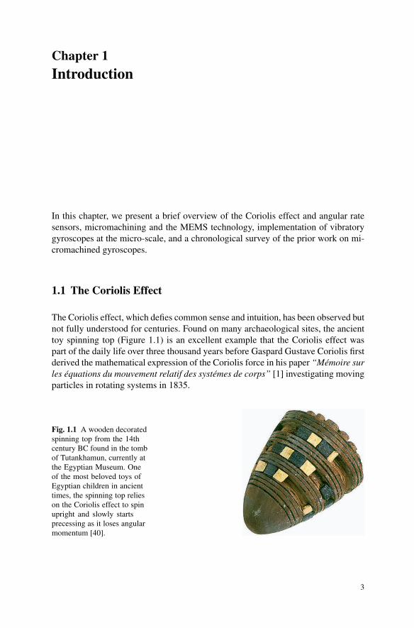
The Coriolis effect, which defies common sense and intuition, has been observed butnot fully understood for centuries. Found on many archaeological sites, the ancienttoy spinning top (Figure 1.1) is an excellent example that the Coriolis effect waspart of the daily life over three thousand years before Gaspard Gustave Coriolis firstderived the mathematical expression of the Coriolis force in his paper “Memoire surles equations du mouvement relatif des systemes de corps” [1] investigating movingparticles in rotating systems in 1835.
Fig. 1.1 A wooden decoratedspinning top from the 14thcentury BC found in the tombof Tutankhamun, currently atthe Egyptian Museum. Oneof the most beloved toys ofEgyptian children in ancienttimes, the spinning top relieson the Coriolis effect to spinupright and slowly startsprecessing as it loses angularmomentum [40].
3
4 1 Introduction
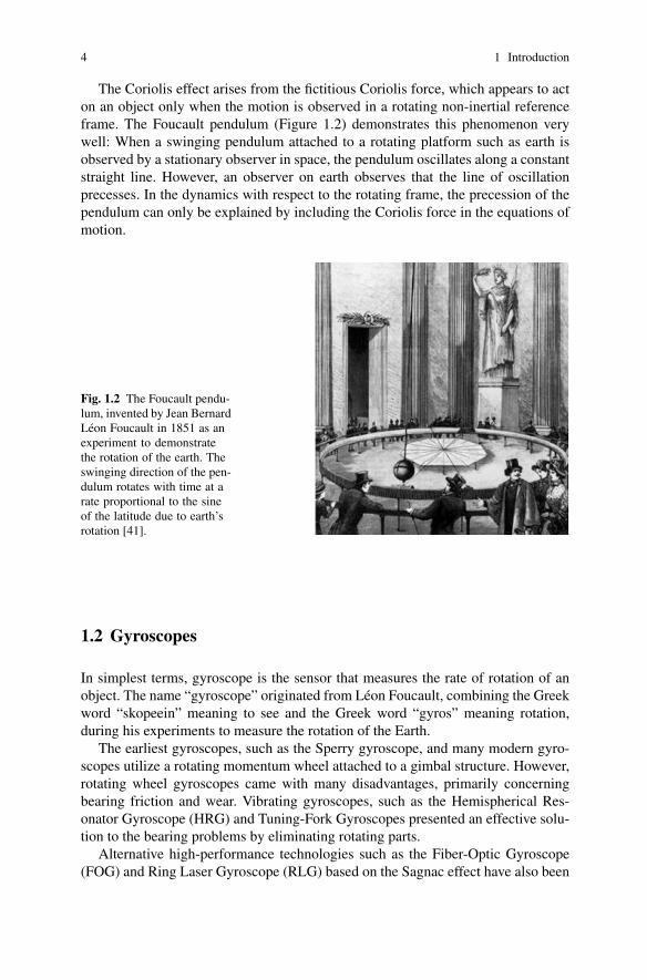
The Coriolis effect arises from the fictitious Coriolis force, which appears to acton an object only when the motion is observed in a rotating non-inertial referenceframe. The Foucault pendulum (Figure 1.2) demonstrates this phenomenon verywell: When a swinging pendulum attached to a rotating platform such as earth isobserved by a stationary observer in space, the pendulum oscillates along a constantstraight line. However, an observer on earth observes that the line of oscillationprecesses. In the dynamics with respect to the rotating frame, the precession of thependulum can only be explained by including the Coriolis force in the equations ofmotion.
Fig. 1.2 The Foucault pendu-lum, invented by Jean BernardLeon Foucault in 1851 as anexperiment to demonstratethe rotation of the earth. Theswinging direction of the pen-dulum rotates with time at arate proportional to the sineof the latitude due to earth’srotation [41].
1.2 Gyroscopes
In simplest terms, gyroscope is the sensor that measures the rate of rotation of anobject. The name “gyroscope” originated from Leon Foucault, combining the Greekword “skopeein” meaning to see and the Greek word “gyros” meaning rotation,during his experiments to measure the rotation of the Earth.
The earliest gyroscopes, such as the Sperry gyroscope, and many modern gyro-scopes utilize a rotating momentum wheel attached to a gimbal structure. However,rotating wheel gyroscopes came with many disadvantages, primarily concerningbearing friction and wear. Vibrating gyroscopes, such as the Hemispherical Res-onator Gyroscope (HRG) and Tuning-Fork Gyroscopes presented an effective solu-tion to the bearing problems by eliminating rotating parts.
Alternative high-performance technologies such as the Fiber-Optic Gyroscope(FOG) and Ring Laser Gyroscope (RLG) based on the Sagnac effect have also been

1.3 The MEMS Technology 5
developed. By eliminating virtually all mechanical limitations such as vibration andshock sensitivity and friction, these optical gyroscopes found many high-end appli-cations despite their high costs.
Fig. 1.3 One of the firstexamples of the gyrocompass,developed in the early 1800s.The gyrocompass gainedpopularity, especially in steelships, since steel blocked theability of magnetic compassesto find magnetic north.
1.3 The MEMS Technology
As the name implies, Microelectromechanical Systems (MEMS) is the technol-ogy that combines electrical and mechanical systems at a micro scale. Practically,any device fabricated using photo-lithography based techniques with micrometer(1µm = 10−6m) scale features that utilizes both electrical and mechanical functionscould be considered MEMS.
Evolved from the semiconductor fabrication technologies, the most striking fea-ture of the MEMS technology is that it allows building moving micro-structures ona substrate. With this capability, extremely complex mechanical and electrical sys-tems can be created. Masses, flexures, actuators, detectors, levers, linkages, gears,dampers, and many other functional building blocks can be combined to build com-plete sophisticated systems on a chip. Inertial sensors such as accelerometers andgyroscopes utilize this capability to its fullest.
Photolithography based pattern transfer methods and successive patterning ofthin structural layers adapted from standard IC fabrication processes are the en-abling technologies behind micromachining. By dramatically miniaturizing andbatch processing complete electro-mechanical systems, substantial reductions in de-vice size, weight and cost are achieved.
6 1 Introduction
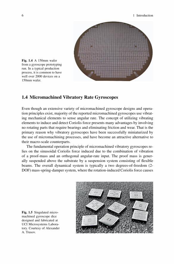
Fig. 1.4 A 150mm waferfrom a gyroscope prototypingrun. In a typical productionprocess, it is common to havewell over 2000 devices on a150mm wafer.
1.4 Micromachined Vibratory Rate Gyroscopes
Even though an extensive variety of micromachined gyroscope designs and opera-tion principles exist, majority of the reported micromachined gyroscopes use vibrat-ing mechanical elements to sense angular rate. The concept of utilizing vibratingelements to induce and detect Coriolis force presents many advantages by involvingno rotating parts that require bearings and eliminating friction and wear. That is theprimary reason why vibratory gyroscopes have been successfully miniaturized bythe use of micromachining processes, and have become an attractive alternative totheir macro-scale counterparts.
The fundamental operation principle of micromachined vibratory gyroscopes re-lies on the sinusoidal Coriolis force induced due to the combination of vibrationof a proof-mass and an orthogonal angular-rate input. The proof mass is gener-ally suspended above the substrate by a suspension system consisting of flexiblebeams. The overall dynamical system is typically a two degrees-of-freedom (2-DOF) mass-spring-damper system, where the rotation-induced Coriolis force causes
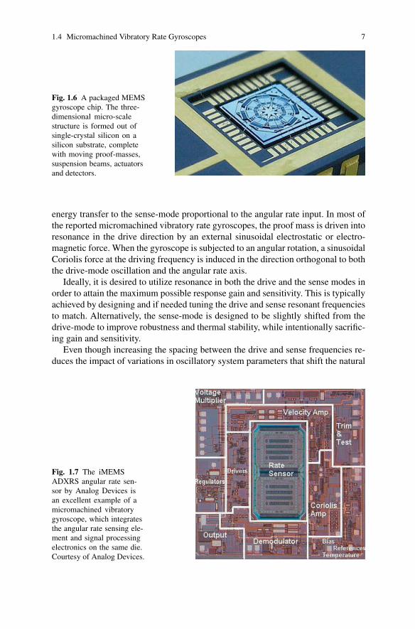
Fig. 1.5 Singulated micro-machined gyroscope dicedesigned and fabricated atUCI Microsystems Labora-tory. Courtesy of AlexanderA. Trusov.
1.4 Micromachined Vibratory Rate Gyroscopes 7
Fig. 1.6 A packaged MEMSgyroscope chip. The three-dimensional micro-scalestructure is formed out ofsingle-crystal silicon on asilicon substrate, completewith moving proof-masses,suspension beams, actuatorsand detectors.
energy transfer to the sense-mode proportional to the angular rate input. In most ofthe reported micromachined vibratory rate gyroscopes, the proof mass is driven intoresonance in the drive direction by an external sinusoidal electrostatic or electro-magnetic force. When the gyroscope is subjected to an angular rotation, a sinusoidalCoriolis force at the driving frequency is induced in the direction orthogonal to boththe drive-mode oscillation and the angular rate axis.
Ideally, it is desired to utilize resonance in both the drive and the sense modes inorder to attain the maximum possible response gain and sensitivity. This is typicallyachieved by designing and if needed tuning the drive and sense resonant frequenciesto match. Alternatively, the sense-mode is designed to be slightly shifted from thedrive-mode to improve robustness and thermal stability, while intentionally sacrific-ing gain and sensitivity.
Even though increasing the spacing between the drive and sense frequencies re-duces the impact of variations in oscillatory system parameters that shift the natural
Fig. 1.7 The iMEMSADXRS angular rate sen-sor by Analog Devices isan excellent example of amicromachined vibratorygyroscope, which integratesthe angular rate sensing ele-ment and signal processingelectronics on the same die.Courtesy of Analog Devices.
8 1 Introduction
frequencies and damping values, the resulting errors still require compensation byadvanced control and signal processing architectures.
1.5 Applications of MEMS Gyroscopes
As their performance keeps constantly improving in time, micromachined gyro-scopes are becoming a viable alternative to expensive and bulky conventional in-ertial sensors. High-performance angular rate sensors such as precision fiber-opticgyroscopes, ring laser gyroscopes, and conventional rotating wheel gyroscopes areusually too expensive and too large for use in most emerging applications. With mi-cromachining processes that allow batch production of micro-electro-mechanicalsystems on a chip similar to integrated circuits, unit costs unimaginable in anyother technology are achieved. Moreover, advances in the fabrication techniquesthat allow electronics to be integrated on the same silicon chip together with themechanical sensor elements provide an unmatched integration capability. Conse-quently, miniaturization of vibratory gyroscopes with innovative micro-fabricationprocesses and gyroscope designs is already becoming an attractive solution to cur-rent inertial sensing market needs, and even opening new market opportunities.
With their dramatically reduced cost, size, and weight, MEMS gyroscopes po-tentially have a wide application spectrum in the aerospace industry, military, auto-motive and consumer electronics markets. The automotive industry applications arediverse, including advanced automotive safety systems such as electronic stabilitycontrol (ESC), high performance navigation and guidance systems, ride stabiliza-tion, roll-over detection and prevention, and next generation airbag and brake sys-tems. A wide range of consumer electronics applications with very high volumesinclude image stabilization in digital cameras and camcorders, virtual reality prod-ucts, inertial pointing devices, and computer gaming industry. Miniaturization ofgyroscopes also enable higher-end applications including micro-satellites, micro-robotics, and even implantable devices to cure vestibular disorders.
1.6 Gyroscope Performance Specifications
The specifications and test procedures for rate gyroscopes are outlined in the IEEEStandard Specification Format Guide and Test Procedure for Coriolis Vibratory Gy-ros [2]. The following is a summary of important specifications and definitions fromIEEE Standard for Inertial Sensor Terminology [3].
Scale factor:The ratio of a change in output to a change in the input intended to be measured, typ-ically specified in mV/◦/sec, and evaluated as the slope of the least squares straightline fit to input-output data. Scale factor error specifications include:
1.6 Gyroscope Performance Specifications 9
Linearity error: The deviation of the output from a least-squares linear fit of theinput-output data. It is generally expressed as a percentage of full scale, or percentof output.Nonlinearity: The systematic deviation from the straight line that defines the nomi-nal input-output relationship.Scale factor temperature and acceleration sensitivity: The change in scale factorresulting from a change in steady state operating temperature and a constant accel-eration.Asymmetry error: The difference between the scale factor measured with positiveinput and that measured with negative input, specified as a fraction of the scale fac-tor measured over the input range.Scale factor stability: The variation in scale factor over a specified time of continu-ous operation. Ambient temperature, power supply and additional factors pertinentto the particular application should be specified.
Bias (zero rate output):The average over a specified time of gyro output measured at specified operatingconditions that has no correlation with input rotation. Bias is typically expressed in◦/sec or ◦/hr. The zero-rate output drift rate specifications include:Random drift rate: The random time-varying component of drift rate. Random driftrate is usually defined in terms of the Allan variance components:a) Angle Random Walk: The angular error buildup with time that is due to whitenoise in angular rate, typically expressed in ◦/
√hr or ◦/s/
√hr.
b) Bias Instability: The random variation in bias as computed over specified finitesample time and averaging time intervals, characterized by a 1/ f power spectraldensity, typically expressed in ◦/hr.c) Rate Random Walk: The drift rate error buildup with time that is due to whitenoise in angular acceleration, typically expressed in ◦/hr/
√hr.
Environmentally sensitive drift rate: Components of drift rate dependent on environ-mental parameters, including acceleration sensitivity, temperature sensitivity, tem-perature gradient sensitivity, temperature hysteresis and vibration sensitivity.
Operating range (input rate limits):Range of positive and negative angular rates that can be detected without saturation.
Resolution:The largest value of the minimum change in input, for inputs greater than the noiselevel, that produces a change in output equal to some specified percentage (at least50%) of the change in output expected using the nominal scale factor.
Bandwidth:The range of frequency of the angular rate input that the gyroscope can detect. Typ-ically specified as the cutoff frequency coinciding to the -3dB point. Alternatively,the frequency response or transfer function could be specified.

10 1 Introduction
Turn-on time:The time from the initial application of power until a sensor produces a specifieduseful output, though not necessarily at the accuracy of full specification perfor-mance.
Linear and angular vibration sensitivity:The ratio of the change in output due to linear and angular vibration about a sensoraxis to the amplitude of the angular vibration causing it.
Shock resistance:Maximum shock that the operating or non-operating device can endure without fail-ure, and conform to all performance requirements after exposure. Pulse duration andshape have to be specified. Full recovery time after exposure can also be specified.
Reliability requirements such as operating life, operating temperature range, ther-mal shock, thermal cycling, humidity, electrostatic discharge (ESD) immunity, andelectromagnetic emissions and susceptibilities are also typically specified in manyapplications.
1.7 A Survey of Prior Work on MEMS Gyroscopes
Since the first demonstration of a micromachined gyroscope by the Draper Labora-tory in 1991 [6], various micromachined gyroscope designs fabricated in a varietyof processes including surface, bulk and hybrid surface-bulk micromachining tech-nologies or alternative fabrication techniques have been reported in the literature.The development of miniaturized piezoelectric gyroscopes, for example the quartztuning-fork by Systron Donner [7] and the fused-quartz HRG by Delco [8], dateback to the early 1980’s. Incompatibility of quartz devices with IC fabrication tech-nologies and the know-how generated from micromachined accelerometers in thesame era led to several successful academic and commercial silicon-based microgy-roscopes over the following decades.
1.7.0.1 Important Development Milestones
The evolution of the design and performance of silicon micromachined gyro-scopes is better understood by investigating the important development milestonesin chronological order:
• Draper Laboratory reported the first micromachined gyroscope in 1991, utilizinga double-gimbal single crystal silicon structure suspended by torsional flexures;and demonstrated 4◦/s/
√Hz resolution at 60Hz bandwidth [6].
• In 1993, Draper Laboratory reported their next generation silicon-on-glass tun-ing fork gyroscope with 1◦/s/
√Hz resolution. The glass substrate aimed to min-
imize stray capacitance. The tuning fork proof masses were driven out of-phase
1.7 A Survey of Prior Work on MEMS Gyroscopes 11
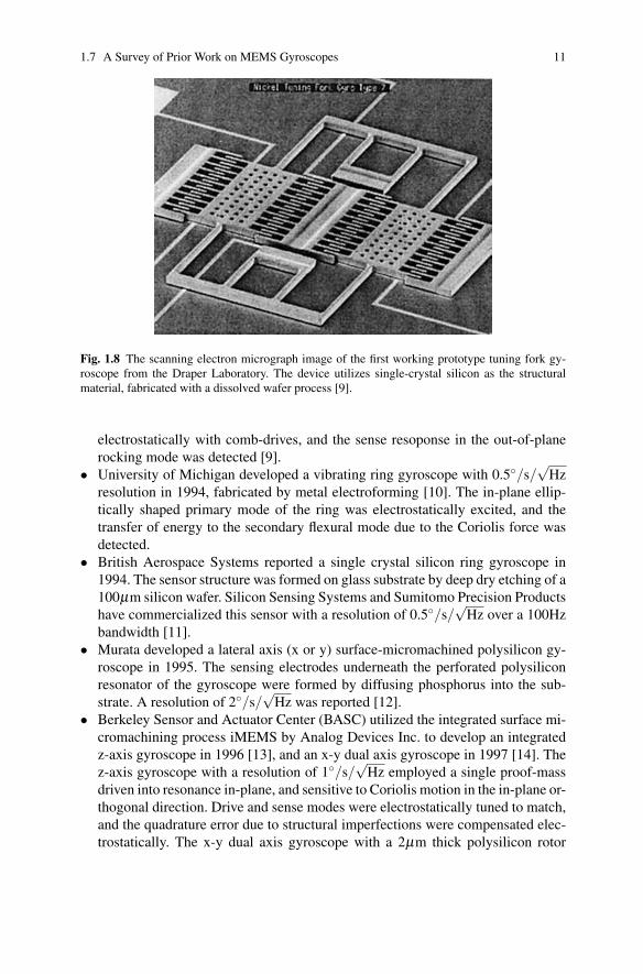
Fig. 1.8 The scanning electron micrograph image of the first working prototype tuning fork gy-roscope from the Draper Laboratory. The device utilizes single-crystal silicon as the structuralmaterial, fabricated with a dissolved wafer process [9].
electrostatically with comb-drives, and the sense resoponse in the out-of-planerocking mode was detected [9].
• University of Michigan developed a vibrating ring gyroscope with 0.5◦/s/√
Hzresolution in 1994, fabricated by metal electroforming [10]. The in-plane ellip-tically shaped primary mode of the ring was electrostatically excited, and thetransfer of energy to the secondary flexural mode due to the Coriolis force wasdetected.
• British Aerospace Systems reported a single crystal silicon ring gyroscope in1994. The sensor structure was formed on glass substrate by deep dry etching of a100µm silicon wafer. Silicon Sensing Systems and Sumitomo Precision Productshave commercialized this sensor with a resolution of 0.5◦/s/
√Hz over a 100Hz
bandwidth [11].• Murata developed a lateral axis (x or y) surface-micromachined polysilicon gy-
roscope in 1995. The sensing electrodes underneath the perforated polysiliconresonator of the gyroscope were formed by diffusing phosphorus into the sub-strate. A resolution of 2◦/s/
√Hz was reported [12].
• Berkeley Sensor and Actuator Center (BASC) utilized the integrated surface mi-cromachining process iMEMS by Analog Devices Inc. to develop an integratedz-axis gyroscope in 1996 [13], and an x-y dual axis gyroscope in 1997 [14]. Thez-axis gyroscope with a resolution of 1◦/s/
√Hz employed a single proof-mass
driven into resonance in-plane, and sensitive to Coriolis motion in the in-plane or-thogonal direction. Drive and sense modes were electrostatically tuned to match,and the quadrature error due to structural imperfections were compensated elec-trostatically. The x-y dual axis gyroscope with a 2µm thick polysilicon rotor
12 1 Introduction
disc utilized torsional drive-mode excitation and two orthogonal torsional sensemodes to achieve a resolution of 0.24◦/s/
√Hz.
• In 1997, Robert Bosch Gmbh. reported z-axis micromachined tuning-fork gyro-scope design that utilizes electromagnetic drive and capacitive sensing for auto-motive applications, with a resolution of 0.4◦/s/
√Hz [15]. Through the use of a
permanent magnet inside the sensor package, drive-mode amplitudes in the orderof 50µm were achieved.
• Jet Propulsion Laboratory (JPL) developed a bulk micromachined clover-leafshaped gyroscope in 1997 together with UCLA. The device had a metal postepoxied inside a hole on the silicon resonator to increase the rotational inertia ofthe sensing element. A resolution of 70◦/hr/
√Hz was demonstrated [16].
• Delphi reported a vibratory ring gyroscope with an electroplated metal ring struc-ture in 1997. The ring was built on top of CMOS chips, and suspended bysemicircular rings. The measured noise floor was 0.1◦/s/
√Hz with 25 Hz band-
width [17].• In 1997, Samsung presented a 7.5µm thick low-pressure chemical vapor de-
posited polysilicon gyroscope with 0.3µm polysilicon lower sensing electrodes[18], similar to Murata’s sensor. The device exhibited 0.1◦/s/
√Hz resolution
with vacuum-packaging. An in-plane device with four fish-hook spring suspen-sion was also demonstrated with the same resolution [19].
• Daimler Benz reported an SOI-based bulk-micromachined tuning-fork gyro-scope with piezoelectric drive and piezoresistive detection in 1997. Piezoelectricaluminum nitride was deposited on one of the tines as the actuator layer, and therotation induced shear stress in the step of the tuning fork was piezoresistivelydetected [20].
• Allied Signal developed bulk-micromachined single crystal silicon sensors in1998, and demonstrated a resolution of 18◦/hr/
√Hz at 100Hz bandwidth [21].
• Draper Laboratories reported a 10µm thick surface-micromachined polysilicongyroscope in 1998. The resolution was improved to 10◦/hr/
√Hz at 60Hz band-
width in 1993, with temperature compensation and better control techniques [22].• In 1999, Murata developed a DRIE-based 50µm thick bulk micromachined sin-
gle crystal silicon gyroscope with independent beams for drive and detectionmodes, which aimed to minimize undesired coupling between the drive and sensemodes. A resolution of 0.07◦/s/
√Hz was demonstrated at 10Hz bandwidth [23].
• Robert Bosch Gmbh. developed a surface micromachined gyroscope with thickpolysilicon structural layer in 1999. The device with 12µm thick polysiliconlayer demonstrated a 0.4◦/s/
√Hz resolution at 100Hz bandwidth [24].
• Samsung demonstrated a wafer-level vacuum packaged 40µm thick bulk mi-cromachined single crystal silicon sensor with mode decoupling in 2000, andreported a resolution of 0.013◦/s/
√Hz [25].
• Seoul National University reported a hybrid surface-bulk micromachining pro-cess in 2000. The device with 40µm thick single crystal silicon demonstrated aresolution of 9◦/hr/
√Hz at 100Hz bandwidth [26].
• In 2000, a z-axis vibratory gyroscope with digital output was developed at BSAC,utilizing the CMOS-compatible IMEMS process by Sandia National Laborato-
1.7 A Survey of Prior Work on MEMS Gyroscopes 13
ries. Parallel-plate electrostatic actuation provided low actuation voltages withlimited drive-mode amplitude. 3◦/s/
√Hz resolution was demonstrated at atmo-
spheric pressure [27].• Carnegie-Mellon University demonstrated both lateral-axis [28] and z-axis [29]
integrated gyroscopes with noise floor of about 0.5◦/s/√
Hz using a masklesspost-CMOS micromachining process in 2001. The lateral-axis gyroscope with 5µm thick structure was fabricated by a thin-film CMOS process, starting withAgilent 0.5µm three-metal CMOS. Excessive curling was observed due to theresidual stress and thermal expansion coefficient mismatch in the structure, andlimited the device size. The 8µm thick z-axis integrated gyroscope was fabricatedstarting with UMC 0.18µm six copper layer CMOS.
• HSG-IMIT reported in 2002 a gyroscope with excellent structural decouplingof drive and sense modes, fabricated in the standard Bosch fabrication processfeaturing 10µm thick polysilicon structural layer. A resolution of 25◦/hr/
√Hz
with 100Hz bandwidth was reported [30].• Analog Devices Inc. developed a dual-resonator z-axis gyroscope in 2002, fab-
ricated in the iMEMS process by ADI with a 4µm thick polysilicon structurallayer. The device utilized two identical proof masses driven into resonance in op-posite directions to reject external linear accelerations, and the differential outputof the two Coriolis signals was detected. On-chip control and detection elec-tronics provided self oscillation, phase control, demodulation and temperaturecompensation. This first commercial integrated micromachined gyroscope had ameasured noise floor of 0.05◦/s/
√Hz at 100Hz bandwidth [31].
• An integrated micromachined gyroscope with resonant sensing was reported in2002 by BSAC. Fabricated in the IMEMS process by Sandia National Laborato-ries, the device utilized frequency shift of double-ended tuning forks (DETF) dueto the generated Coriolis force. A resolution of 0.3◦/s/
√Hz was demonstrated
with the on-chip integrated electronics [32].• In 2002, University of Michigan reported their 150µm thick bulk micromachined
single crystal silicon vibrating ring gyroscope, with 10.4◦/hr/√
Hz resolution[33].
• In 2003, Carnegie-Mellon University demonstrated a DRIE CMOS-MEMS lat-eral axis gyroscope with a measured noise floor of 0.02◦/s/
√Hz at 5 Hz, fab-
ricated by post-CMOS micromachining that uses interconnect metal layers tomask the structural etch steps. The device employs a combination of 1.8µm thin-film structures for springs with out-of-plane compliance and 60µm bulk siliconstructures defined by DRIE for the proof mass and springs with out-of-plane stiff-ness, with on-chip CMOS circuitry. Complete etch removal of selective siliconregions provides electrical isolation of bulk silicon to obtain individually con-trollable comb fingers. Excessive curling is eliminated in the device, which wasproblematic in prior thin-film CMOS-MEMS gyroscopes [34].
• In 2004, Honeywell presented the experimental results on commercial devel-opment of MEMS vibratory gyroscopes [35], the adaptation of the tuning forkarchitecture originally developed by Draper’s Laboratory. The demonstrated per-
14 1 Introduction
formance of the gyro was 1440◦/s operation range, less than 30◦/hr bias in-runstability, and 0.05◦/
√hr angle random walk.
• In 2005, a bulk micromachined gyroscope with bandwidth of 58 Hz and 0.3◦/hrbias stability tested in 10 mTorr pressure was presented by Seoul National Uni-versity [36], however not enough details on design and testing conditions weregiven to independently verify the performance characteristics reported. Therewere no subsequent publications on the design supporting the data.
• In 2006, Microsystems Laboratory at UCIrvine introduced a design architectureof vibratory gyroscope with 1-DOF drive-mode and 2-DOF sense-mode [63].The architecture provided a gain and phase stable operation region in the sense-mode frequency response to achieve inherent robustness at the sensing elementlevel. The gyroscope exhibited a measured noise floor of 0.64◦/s/
√Hz at 50 Hz
in atmospheric pressure with external discrete electronics.• In 2007, Georgia Institute of Technology demonstrated a vibratory silicon gy-
roscope in a tuning fork arrangement to achieve 0.2◦/hr bias drift with auto-matic mode-matching and sense-mode Quality factor of 36,000. The sense modeis automatically tuned down by the ASIC until the zero-rate output is maxi-mized [37]. On the same device, 5.4◦/hr bias drift and 1.5 Hz bandwidth for 2 Hzmode-mismatch and Quality factor of 10,000 at fixed temperature, and 0.96◦/hrbias drift and 0.4bHz bandwidth for 0 Hz mode-mismatch and Quality factor of40,000 were previously reported [38].
• In 2008, Microsystems Laboratory at UCIrvine improved the design architectureof structurally robust MEMS gyroscopes [151] and demonstrated high opera-tional frequency devices (over 2.5kHz) and bandwidth over 250 Hz, with theuncompensated temperature coefficients of bias and scale factor of 313◦/hr/◦Cand 351 ppm/◦C, respectively. With off-chip detection electronics, the measuredresolution was 0.09 ◦/s/
√Hz and the bias drift was 0.08 ◦/s.
1.8 The Robustness Challenge
The tolerancing capabilities of the current photolithography processes and micro-fabrication techniques are inadequate compared to the requirements for productionof high-performance inertial sensors. The resulting inherent imperfections in themechanical structure significantly limits the performance, stability, and robustnessof MEMS gyroscopes [45, 61]. Thus, fabrication and commercialization of high-performance and reliable MEMS gyroscopes that require picometer-scale displace-ment measurements of a vibratory mass have proven to be extremely challeng-ing [4, 43].
In micromachined vibratory rate gyroscopes, the mode-matching requirementrenders the system response very sensitive to variations in system parameters due tofabrication imperfections and fluctuations in operating conditions. Inevitable fabri-cation imperfections affect both the geometry and the material properties of MEMSdevices [61], and shift the drive and sense-mode resonant frequencies. The dynami-
1.9 Inherently Robust Systems 15
cal system characteristics are observed to deviate drastically from the designed val-ues and also from device to device, due to slight variations in photolithographysteps, etching processes, deposition conditions or residual stresses. Process controlbecomes extremely critical to minimize die-to-die, wafer-to-wafer, and lot-to-lotvariations.
Fluctuations in the temperature of the structure also perturb the dynamical systemparameters due to the temperature dependence of Young’s Modulus and thermallyinduced localized stresses. Temperature also drastically affects the damping and theQ factor in the drive and sense modes.
Extensive research has focused on design of symmetric suspensions and res-onator systems that provide mode-matching and minimize temperature dependence[91, 92]. Various symmetric gyroscope designs based on enhancing performanceby mode-matching have been reported. However, especially for lightly-damped de-vices, the requirement for mode-matching is well beyond fabrication tolerances; andnone of the symmetric designs can provide the required degree of mode-matchingwithout active tuning and closed-loop feedback control [46, 47]. Also the gain isaffected significantly by fluctuations in damping conditions, which makes the de-vice very vulnerable to any possible vacuum leak in the hermetic package seal oroutgassing within the cavity.
Fabrication imperfections also introduce anisoelasticities due to extremely smallimbalances in the gyroscope suspension. This results in mechanical interferencebetween the modes and undesired mode coupling often much larger than the Coriolismotion. In order to suppress coupled oscillation and drift, various devices have beenreported employing independent suspension beams for the drive and sense modes[85, 87–89, 91, 99].
Consequently, the mechanical sensing elements of micromachined gyroscopesare required to provide excellent performance, stability, and robustness to meet de-manding specifications. Fabrication imperfections and variations, and fluctuations inthe ambient temperature or pressure during the operation time of these devices in-troduce significant errors, which typically require electronic compensation. Closed-loop force-feedback implementations in the sense-mode are known to alleviate thesensitivity to frequency and damping variations, and increase the sensor bandwidth.However, a closed-loop sense-mode requires additional feedback electrodes, andincreases the cost and complexity of both the MEMS device and the electronics.Thus, it is desirable to achieve inherent robustness at the sensing element to mini-mize compensation requirements.
1.9 Inherently Robust Systems
In recent years, a number of gyroscope designs with multiple proof-masses anddifferent operation principles have been proposed to enhance performance and ro-bustness of MEMS gyroscopes [49,50,54,85,87,88,99]. Most of these designs relyon constraining the oscillation degree-of-freedom of the driven mass to lie only in
16 1 Introduction
the drive direction. In these designs, either a part of the Coriolis Force induced onthe driven mass is transferred to the sensing mass while suppressing the motion ofthe sensing mass in drive direction [49, 54, 85, 99]; or the drive direction oscillationof the driven mass is transferred to the sensing mass while the driven mass is not al-lowed to oscillate in the sense direction [50,87,88]. These designs are still virtuallytwo degrees-of-freedom systems, however, they offer various advantages from thedrive and sense mode decoupling and mode-matching points of view.
Multiple degrees-of-freedom resonators providing larger drive-direction ampli-tudes for improving the performance of vibratory MEMS devices have also beenrecently reported [52, 53, 56, 89, 93]. Two degrees-of-freedom oscillators utilizingmechanical amplification of motion for large oscillation amplitudes have been pro-posed, however, no results on integration of this oscillator system into MEMS gy-roscopes have been indicated [52, 53, 93].
1.10 Overview
This book is organized in two parts. The first part reviews the fundamental oper-ational principles of micromachined vibratory gyroscopes, mechanical sensing el-ement design and practical implementation aspects, electrical design and system-level architectures for actuation and detection, basics of microfabrication methodsused for MEMS gyroscopes, and test and characterization techniques. The secondpart reviews new dynamical systems and structural designs for micromachined gy-roscopes, that will provide inherent robustness against structural and environmen-tal parameter variations, and require less demanding active compensation schemes.The basic approach is to achieve a frequency response with an operating frequencyregion where the response gain and phase are stable, in contrast to a resonant con-ventional system.