2D Process Modeling with Silvaco ATHENA Dr. Lynn Fuller - People

© July 30, 2015 Dr. Lynn Fuller
Smart Phone MEMS Labs
Page 1
Rochester Institute of Technology
Microelectronic Engineering
ROCHESTER INSTITUTE OF TECHNOLOGY MICROELECTRONIC ENGINEERING
MEMS Gyroscope Lab
Dr. Lynn Fuller Kennedy Jensen
Webpage: http://people.rit.edu/lffeee Microelectronic Engineering
Rochester Institute of Technology 82 Lomb Memorial Drive Rochester, NY 14623-5604
Tel (585) 475-2035 Email: [email protected]
Department webpage: http://www.microe.rit.edu
July 30, 2015 SmartPhoneGyroscope.ppt

© July 30, 2015 Dr. Lynn Fuller
Smart Phone MEMS Labs
Page 2
Rochester Institute of Technology
Microelectronic Engineering
INTRODUCTION
Smart phones have many MEMS sensors inside them including, accelerometers, microphones, cameras, gyroscopes, temperature, humidity, magnetic field sensors and more. Apps can be obtained that will output these sensor signals.

© July 30, 2015 Dr. Lynn Fuller
Smart Phone MEMS Labs
Page 3
Rochester Institute of Technology
Microelectronic Engineering
APPS – FOR ANDROID OS
Andro Sensor – free Location, Accelerometer, Light Level, Magnetic field, Orientation, Proximity, Battery Status and Sound Level. Sensor kinetics – free Accelerometer, Gyroscope, Magnetic Field, Temperature, Humidity, Proximity, Light and Pressure. Wifi analyzer – free signal strength vs wifi channels FrequeSee – free dB versus Frequency Speed Gun uses camera to detect speed Many More……
© July 30, 2015 Dr. Lynn Fuller
Smart Phone MEMS Labs
Page 4
Rochester Institute of Technology
Microelectronic Engineering
INTRODUCTION TO GYROSCOPES
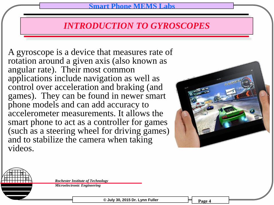
A gyroscope is a device that measures rate of rotation around a given axis (also known as angular rate). Their most common applications include navigation as well as control over acceleration and braking (and games). They can be found in newer smart phone models and can add accuracy to accelerometer measurements. It allows the smart phone to act as a controller for games (such as a steering wheel for driving games) and to stabilize the camera when taking videos.

© July 30, 2015 Dr. Lynn Fuller
Smart Phone MEMS Labs
Page 5
Rochester Institute of Technology
Microelectronic Engineering
ANGULAR RATE
Earth’s Rotation 7.29x10⁻⁵rad/s
Tire Traveling 45mph 52.8rad/s
Ceiling Fan 3.1rad/s
Ferris Wheel 3.3x10⁻²rad/s
Carousel 0.45rad/s
Particle in Hadron Collider
69813rad/s
Angular Rate Angular rate is a vector quantity representing how rapidly angular displacement changes. The SI unit for angular rate is radians per second or rad/s. It is typically represented by the lowercase Greek letter omega (ω).

© July 30, 2015 Dr. Lynn Fuller
Smart Phone MEMS Labs
Page 6
Rochester Institute of Technology
Microelectronic Engineering
ANGULAR RATE
Angular rate for an object moving at a constant rate in a
circle can be calculated in different ways. The formula
ω = 2πf
uses the frequency (f) of the revolutions. Alternatively, the
formula
ω = v/r
uses tangential velocity of the object (v) and the radius of
the revolutions (r).
© July 30, 2015 Dr. Lynn Fuller
Smart Phone MEMS Labs
Page 7
Rochester Institute of Technology
Microelectronic Engineering
INTRODUCTION TO GYROSCOPES
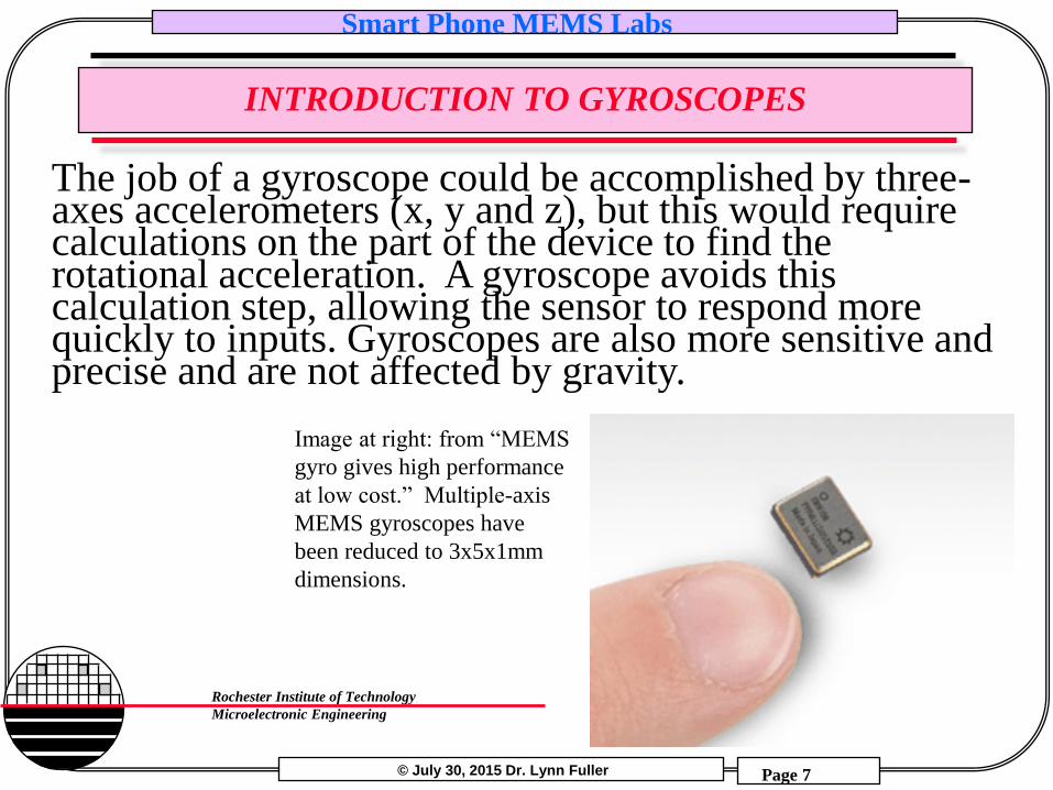
Image at right: from “MEMS
gyro gives high performance
at low cost.” Multiple-axis
MEMS gyroscopes have
been reduced to 3x5x1mm
dimensions.
The job of a gyroscope could be accomplished by three-axes accelerometers (x, y and z), but this would require calculations on the part of the device to find the rotational acceleration. A gyroscope avoids this calculation step, allowing the sensor to respond more quickly to inputs. Gyroscopes are also more sensitive and precise and are not affected by gravity.

© July 30, 2015 Dr. Lynn Fuller
Smart Phone MEMS Labs
Page 8
Rochester Institute of Technology
Microelectronic Engineering
THE THREE AXES OF GYROSCOPES
Three axis gyroscopes can measure angular rate along each axis of the smart phone. Angular rate around the x-axis is known as “roll”, the y-axis as “pitch”, and the z-axis as “yaw”.

© July 30, 2015 Dr. Lynn Fuller
Smart Phone MEMS Labs
Page 9
Rochester Institute of Technology
Microelectronic Engineering
INTRODUCTION TO GYROSCOPES
Most gyroscopes in modern smart phones use changes in capacitance within the sensor to quantify angular rate. The sensors contain a pair of vibrating arms. When an angular rate is applied to the device, it alters the directions of the vibrations of the arms according to the Coriolis effect, which alters the capacitance across the sensor.
Above Image: from Pasolini, shows
directions of mechanical movements in an
actual MEMS gyroscope.

© July 30, 2015 Dr. Lynn Fuller
Smart Phone MEMS Labs
Page 10
Rochester Institute of Technology
Microelectronic Engineering
INTRODUCTION TO GYROSCOPES
Gyroscopes make use of the Coriolis effect to measure angular rate. When an object is moving with velocity v (blue arrow) and an angular rate is applied Ωz (red arrow), a force is created in the y-axis (green arrow). In the vibrating arms of the gyroscope, this force alters the direction of the vibrations, changing the capacitance across the sensor to a degree that can be used to quantify the angular rate.
Y
Z
X m oscillation
or velocity

© July 30, 2015 Dr. Lynn Fuller
Smart Phone MEMS Labs
Page 11
Rochester Institute of Technology
Microelectronic Engineering
INTRODUCTION TO GYROSCOPES
The two vibrating arms within a gyroscope are constantly oscillating in opposite directions. This means that when an angular rate is applied, the Coriolis effect causes forces (green arrows) in opposite directions for the two different arms. This results in a measurable change in capacitance. When a linear acceleration is applied, the forces on the two arms is identical and there is no measurable change in capacitance.

© July 30, 2015 Dr. Lynn Fuller
Smart Phone MEMS Labs
Page 12
Rochester Institute of Technology
Microelectronic Engineering
INTRODUCTION TO GYROSCOPES
The gyroscope is often used together with the accelerometer in the smart phone to create Derived Sensors for detecting and measuring the movement of the device, including both motion from user inputs (turning the smart phone back and forth while playing a game) and motion from the external physical environment (the smart phone sitting in a moving vehicle).

© July 30, 2015 Dr. Lynn Fuller
Smart Phone MEMS Labs
Page 13
Rochester Institute of Technology
Microelectronic Engineering
CHALLENGE OF MINIATURE GYROSCOPES
Acceleration sensors are necessary for calibrating the gyroscopes to avoid “gyroscope drift”: a reduction in the accuracy of gyroscope measurements caused by accumulated errors over time and with heavy use (a large amount of fast movement and changes in acceleration).
Above Image: from Pycke, demonstrates gyroscope drift
over time. The red line shows the angular rate being
measured. The blue line shows the equilibrium point,
which should remain at 0 degrees, but increases overtime
as a result of gyroscope drift.

© July 30, 2015 Dr. Lynn Fuller
Smart Phone MEMS Labs
Page 14
Rochester Institute of Technology
Microelectronic Engineering
GYROSCOPE EXAMPLE
Secure your smartphone to a turntable with a known number of RPM’s (most turntables are standardized to a set number of rpm’s – 33, 45 or 78 rpm’s depending on the type of record that they were designed to play, and some have settings for more than one of these speeds). Calculate the expected angular rate for the your smartphone on the turn table by first converting the frequency from rpm’s (rotations per minute) to rotations per second, and then using the formula:
ω = 2πf
θ
θ = S/r
r
© July 30, 2015 Dr. Lynn Fuller
Smart Phone MEMS Labs
Page 15
Rochester Institute of Technology
Microelectronic Engineering
GYROSCOPE EXAMPLE
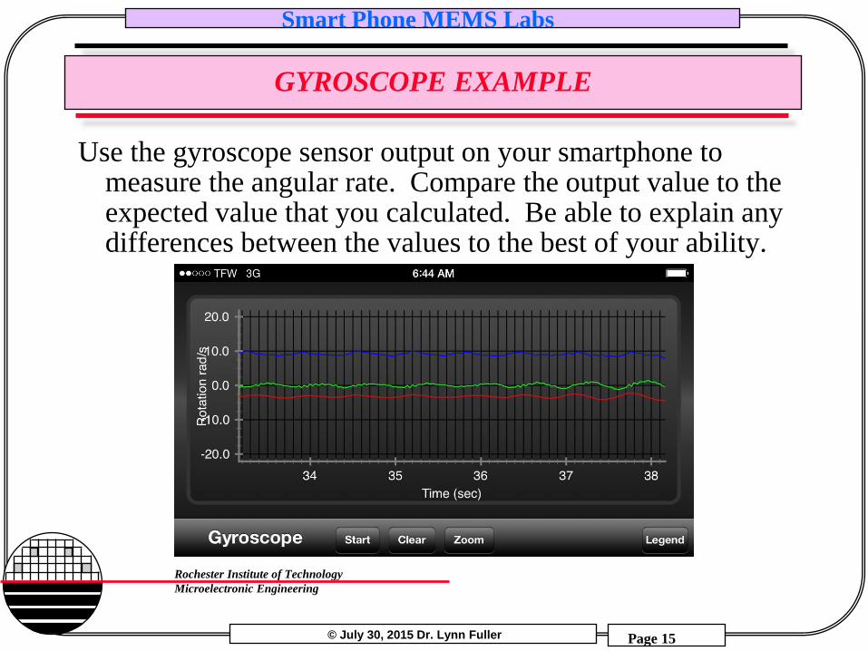
Use the gyroscope sensor output on your smartphone to measure the angular rate. Compare the output value to the expected value that you calculated. Be able to explain any differences between the values to the best of your ability.

© July 30, 2015 Dr. Lynn Fuller
Smart Phone MEMS Labs
Page 16
Rochester Institute of Technology
Microelectronic Engineering
GYROSCOPE EXAMPLE
If you do not have access to a turntable, you can create a similar effect by spinning your smartphone on the end of a string or rope. Take time to determine the best method to ensure your smartphone does not go flying off – perhaps placing it in a sealed bag and attaching that to the string (see pictures of experimental set up below.
© July 30, 2015 Dr. Lynn Fuller
Smart Phone MEMS Labs
Page 17
Rochester Institute of Technology
Microelectronic Engineering
GYROSCOPE EXAMPLE
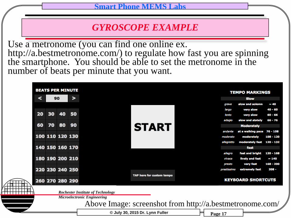
Above Image: screenshot from http://a.bestmetronome.com/
Use a metronome (you can find one online ex. http://a.bestmetronome.com/) to regulate how fast you are spinning the smartphone. You should be able to set the metronome in the number of beats per minute that you want.

© July 30, 2015 Dr. Lynn Fuller
Smart Phone MEMS Labs
Page 18
Rochester Institute of Technology
Microelectronic Engineering
GYROSCOPE EXAMPLE
Spin the smartphone around on the string parallel to the ground so that the phone is in the same place each time the metronome makes a noise. This will make the beats per minute of the metronome equal to the revolutions per minute of the smartphone. Keeping the phone parallel to the ground should help to reduce acceleration in the angular rate as you are spinning the phone and help you keep it at a constant angular velocity.

© July 30, 2015 Dr. Lynn Fuller
Smart Phone MEMS Labs
Page 19
Rochester Institute of Technology
Microelectronic Engineering
GYROSCOPE EXAMPLE
Calculate the expected angular rate by first converting the frequency of the revolutions from revolutions per minute (coming from the beats per minute of the metronome) to revolutions per second, and then using the formula
ω = 2πf
Compare the reading for angular rate of the sensor in the smartphone with the expected angular rate. Be able to explain any differences.
This shows the result of swinging the smartphone as a pendulum from a single string. The graph shows angular rate in all three axes because the smartphone was attached in only one place, and so it rotated as it swung.

© July 30, 2015 Dr. Lynn Fuller
Smart Phone MEMS Labs
Page 20
Rochester Institute of Technology
Microelectronic Engineering
GYROSCOPE EXAMPLE
When the “smartphone on a string” experiment was run, the metronome was set at 90 beats per minute, so the rpm of the smartphone was 90. This value had to be converted to revolutions per second. 90 revolutions/minute x 1 minute/60 seconds = 1.5 revolutions/second This value represents the frequency of the revolutions and can be substituted into the formula ω = 2πf to solve for ω. ω = 2π (1.5 revolutions/second) = 9.42 radians/second
The blue line from when this experiment was run, representing the yaw axis, corresponds closely with the calculated value of 9.42 radians/second. The slight variations in this reading are due to the small changes in the angular rate of the smartphone due to the tension changes required to keep the phone in constant revolution.

© July 30, 2015 Dr. Lynn Fuller
Smart Phone MEMS Labs
Page 21
Rochester Institute of Technology
Microelectronic Engineering
REFERENCES
1. Mechanics of Materials, by Ferdinand P. Beer, E. Russell Johnston, Jr., McGraw-Hill Book Co.1981, ISBN 0-07-004284-5
2. Dr. Fuller’s lecture notes on Accelerometers: http://people.rit.edu/lffeee/eeee688.htm 3. Kircher, Kaleb. “Android: Gyroscope Basics.” Kircher Electronics. Kircher Engineering, 2014. Web. 25 July
2015. 4. Esfandayari, Jay, Roberto De Nuccio, Gang Xu. “Introduction to MEMS Gyroscopes.” Solid State
Technology: Insights for Electronics Manufacturing. ST Microelectronics, 15 November 2010. Web. 10 July 2015.
5. Nasiri, Steve, et al. “Motion Processing: The Next Breakthrough Function In Handsets.” Mobiledev & Design. Penton, 1 July 2010. Web. 10 July 2015.
6. “MEMS Gyroscopes – A revolutionary way to interface with the real world.” YouTube. YouTube, 10 October 2012. Web. 10 July 2015.
7. “How do MEMS gyroscopes work?” YouTube. YouTube, 24 November 2014. Web. 10 July 2015. 8. Nave, Rod. “Basic Rotational Quantities.” HyperPhisics. Georgia State University, 2014. Web. 25 July 2015. 9. Frank, Randy. “Development Forecasts Growth for MEMS & Sensors in Smartphones.” Sensor Tips. WTWH
Media, 30 June 2010. Web. 25 July 2015. 10. Pasolini, Fabio. “MEMS Accelerometers, Gyroscopes, and Geomagnetic Sensors – Propelling Disruptive
Consumer Applications.” Digi-Key Electronics. Digi-Key Corporation, 11 April 2011. Web. 26 July 2015. 11. “MEMS gyro gives high performance at low cost.” Electronic Products. AspenCore, Inc. 29 November 2010.
Web. 2 August 2015. 12. Pycke, Tom. “Gyroscope to roll, pitch and yaw.” MAV-blog. TomPyckeBe, 11 May 2006. Web. 15 July
2015.

© July 30, 2015 Dr. Lynn Fuller
Smart Phone MEMS Labs
Page 22
Rochester Institute of Technology
Microelectronic Engineering
HOMEWORK – GYROSCOPE SENSORS
Use your smart phone to investigate gyroscope sensors. Repeat one of the examples in this document with your phone.

© July 30, 2015 Dr. Lynn Fuller
Smart Phone MEMS Labs
Page 23
Rochester Institute of Technology
Microelectronic Engineering
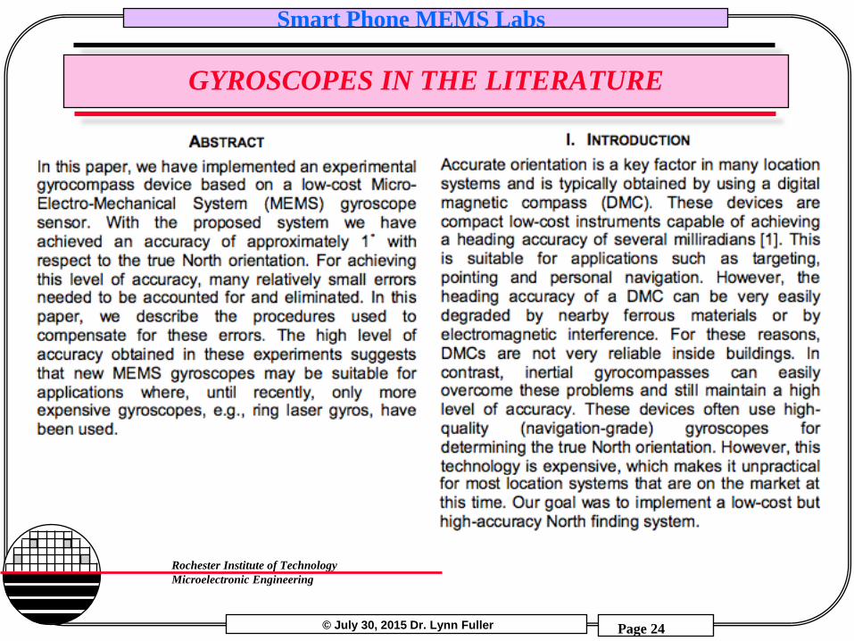
GYROSCOPES IN THE LITERATURE
This paper is taken directly from the following web-available PDF file. All credit belongs to the above authors.
http://www.tkt.cs.tut.fi/research/nappo_files/Iozan_ENC_2010_web.pdf
© July 30, 2015 Dr. Lynn Fuller
Smart Phone MEMS Labs
Page 24
Rochester Institute of Technology
Microelectronic Engineering
GYROSCOPES IN THE LITERATURE

© July 30, 2015 Dr. Lynn Fuller
Smart Phone MEMS Labs
Page 25
Rochester Institute of Technology
Microelectronic Engineering
GYROSCOPES IN THE LITERATURE