
Memory Management Unit - nxp.com · Since the real address is the same as the effective address,...
65
Memory Management Unit 9 - 1 Memory Management Unit What you will learn Learn how to: •Initialize a BAT register •Set up the MMU for Page Translations - Invalidate TLBs - Define size and location of Hashed Page Table - Configure Segment registers for a task - Create the initial Hashed Page Table - Load PTEs into Hashed Page Table Why have an MMU? An MMU has several important uses: •Privilege Control - prevents access of Supervisor areas by User (Problem) level programs. •Cache Control - allows accesses to I/O devices to be non-cacheable while allowing other areas to be cacheable. •Read Protection - prevents loss of data from speculative destructive reads (status flags), while allowing speculative reads from other memory areas •Write Protection - allows selected memory areas to be read-only or treated like ROM. •Memory Protection - restricts programs to accessing only those memory areas needed. Prevents one task from erroneously or maliciously disturbing another tasks memory area. •Address Translation (relocation) - allows multiple programs that may have the same logical address range to reside in memory at the same time, by relocating them where convenient.
Transcript of Memory Management Unit - nxp.com · Since the real address is the same as the effective address,...

Memory Management Unit 9 - 1
Memory Management UnitWhat youwill learn
Learn how to:• Initialize a BAT register• Set up the MMU for Page Translations
- Invalidate TLBs- Define size and location of Hashed Page Table- Configure Segment registers for a task- Create the initial Hashed Page Table- Load PTEs into Hashed Page Table
Why havean MMU?
An MMU has several important uses: • Privilege Control - prevents access of Supervisor areas by User (Problem) level programs. • Cache Control - allows accesses to I/O devices to be non-cacheable while allowing other areas to be cacheable. • Read Protection - prevents loss of data from speculative destructive reads (status flags), while allowing speculative reads from other memory areas • Write Protection - allows selected memory areas to be read-only or treated like ROM. • Memory Protection - restricts programs to accessing only those memory areas needed. Prevents one task from erroneously or maliciously disturbing another tasks memory area. • Address Translation (relocation) - allows multiple programs that may have the same logical address range to reside in memory at the same time, by relocating them where convenient.

Memory Management Unit 9 - 2
What is the 603e MMU?Definition The 603e MMU assigns protection attributes to pages in memory and also
implements address translation.
603e MMU
Instruction TranslationLookaside Buffer
(ITLB)
Data TranslationLookaside Buffer
(DTLB)
EffectiveAddresses
RealAddresses
Instruction Block Address Translation (IBAT)
Data Block Address Translation (DBAT)
BlockDiagram
1. The TLBs are address caches (64 entry, 2-way set associative) that holdrecently used 4K byte page entries.2. The BATs are for large address ranges whose mappings don’t change often.
TLBs andBATs
• The core asserts effective addresses which are converted to real addressesby the MMU.• The MMU also provides protection such as privilege-only access.• Depending on the type of access and the way the MMU has beenprogrammed, the effective address may be handled either by way of a TLB,page addressing, or a BAT.• BAT registers are programmed from reset and changed infrequently or notat all.• TLBs are loaded from hashed page tables and entries are changed out morefrequently.
MMUFunctions

Memory Management Unit 9 - 3
What is Block Address Translation?Definition If an effective address matches the corresponding field of a BAT register, the
information in the BAT register is used to generate the physical address.
EffectiveAddresses
RealAddressesBlock
Diagram IBATU0IBATL0
IBATU1IBATL1
IBATU2IBATL2
IBATU3IBATL3
DBATU0DBATL0
DBATU1DBATL1
DBATU2DBATL2
DBATU3DBATL3
4 gbyte Memory Map
• Block address translation defines up to 8 windows in the memory map, fourfor instructions and four for data.• Data and instruction areas may overlap.• When an effective address is asserted by the task, it is compared against theeight windows defined by the BAT registers. If there is a match, the associatedreal address is asserted. If there is no match, then page translation is executed.• Blocks can vary in size from a minimum of 128K bytes to 256Mbytes.
Characteristicsof BlockAddress
Translation

Memory Management Unit 9 - 4
BAT Programming Model
BEPI Res
Reserved
D or IBATxU - Upper BAT Registers, x=0-3 P. 7-25
0 1 2 3 4 5 6 7 8 9 10 11 12 13 14 15
16 17 18 19 20 21 22 23 24 25 26 27 28 29 30 31BL VS VP
BRPN Res
Reserved
D or IBATxL - Lower BAT Registers, x=0-3 P. 7-25
0 1 2 3 4 5 6 7 8 9 10 11 12 13 14 15
16 17 18 19 20 21 22 23 24 25 26 27 28 29 30 31WIMG* PPRes
*Attempts to write one to W and G in the IBAT registers causes boundedly-undefined results.
• The complete programming model for Block Address Translation consistsof 8 register pairs, structured as shown, four for instructions and four for data.
Summary

Memory Management Unit 9 - 5
How BAT OperatesIntroduction The diagram below shows the flow of BAT operation. It assumes the block
protection bits, PP, are compatible. If not, a DSI or ISI exception occurs.
Start
Compare EA[0:14] with BEPI & ~BL in the IBATU registers if a fetch or DBATU registers if a load or store
Match? N BAT array miss
Y
Compare MSR[PR]=0 & VS=1 or MSR[PR]=1 & VP=1
Match? N BAT array miss
Y
Assert Real Address = BRPN plus EA[15:31]
End
FlowDiagram
1. Operation begins with the assertion of an effective address.2. The top 15 bits of the effective address is compared with the top bits of theBEPI field in the upper BAT registers either instruction or data depending onthe type of access. The number of bits that actually are compared isdetermined by the BL field in the upper BAT register.3. If there is no match with any of the four BAT registers, the access is aBAT miss. Following a BAT miss the MMU attempts to translate the addressusing a TLB or page translation.4. If there is a match, then the protection attributes are checked. If theprotection attributes don’t allow an this access, then the result is again a BATmiss. In this case, an xSI exception is taken.5. If the protection matches, then BRPN is concatenated with bits 16-31 areused to form the real address.
Descriptionof Flow

Memory Management Unit 9 - 6
How to Locate a Block of Memory (1 of 2)
Hex numbers
Binary numbers
Use the following templates to fill in the individual fields, then convert tohex register values:Procedure
Introduction This example shows how to locate a block of memory.
0
MIW G
0
IBATU
BEPI BL VS VP
0000
RegisterHex Value
IBATL
BRPN PP
0
RegisterHex Value
00
1. Because the bit fields of the BAT registers do not easily line up with the hex boundaries, thesetemplates can be helpful.2. The colors identify the fields within the register.3. Boxes outlining various fields in a register contain bits if the box is outlined with a thick line orhex digits if outlined with a thin line.4. Let’s try this out with an example.

Memory Management Unit 9 - 7
0F011
100110F
M
0
I
0
W
0
G
0 0
How to Locate a Block of Memory (2 of 2)
IBATU 0
BEPI
F
BL VS
1
VP
00000 00 FFFC0006
RegisterHex Value
IBATL 0
BRPN PP
0FFFC0003
RegisterHex Value
0
Hex numbers
Binary numbers
Example Locate a block of read-only memory at address 0xFFFC0000. The lengthof the memory is 256K. Assume effective address equals real address andonly instructions are in the memory. Block should be accessible by thesupervisor only.
F C 0 6
F F C 0 01 1
3
1. The effective address is 0xFFFC0000 so in BEPI, the Block Effective Page Index, is initializedto 0xFFF followed by binary 110, the 3 most significant bits of 0xC.2. Since the real address is the same as the effective address, BRPN, the Block Real Page number,is initialized similarly.3. According to Table 7-9 on p. 7-26, the value for BL if the memory is 256K bytes is binary allzeroes except a one in the least significant bit.4. This block is to be accessible by the supervisor only; therefore VS is 1 and VP is zero.5. The problem doesn’t state much about the WIMG bits, but since it is instruction-only, W and Gmust be zero. Nothing is said about an external master; therefore, M is assigned zero. Finally, sinceenabling the cache enhances performance, I is assigned zero.6. According to Table 7-10 on p. 7-28, read-only permission is x1 so PP is assigned binary 11.7. The final register values are shown.

Memory Management Unit 9 - 8
How to Initialize the MMU for BAT (1 of 2)Introduction Here we describe the steps in initializing the MMU for BAT. Reset
conditions are assumed.
Action Here are the steps in initialization:
Step Action ExampleClear BAT registers li r22,0
mtibatu 0,r22 - mtibatu 3,r22 mtdbatu 0,r22 - mtdbatu 3,r22
1
Init lower BAT registerBRPN:real page addr[0:14]WIMG:attribute bitsPP:access protection
(7-25)
2 lis r22,0xFFFC ori r22,r22,3 mtibatl 0,r22
(Continued on next page)
1. First the valid bits of the upper BAT registers must be cleared..2. Next, any required lower BAT registers are initialized.

Memory Management Unit 9 - 9
How to Initialize the MMU for BAT (2 of 2)
Action Step Action ExampleInit upper BAT register
BEPI:effective addr[0:14]BL:block lengthVS:privilege mode validVP:problem mode valid
(7-25)
3 lis r22,0xFFFC ori r22,r22,6 mtibatu 0,r22
Repeat steps 2 and 3 foreach required lower-upperpair BAT registers.
4
Execute isync5 isync
Caution It is the responsibility of the software to insure that an effective address istranslated by only one IBAT and only one DBAT. If this is not done, resultsare undefined.
1. Then the lower BAT registers are initialized.2. After all the registers are initialized, execute an isync instruction. This will insure that allprevious instruction have been completed before proceeding.

Memory Management Unit 9 - 10
Exercise-Initialize MMU for BAT (1 of 2)A system is to have 2 memory areas for Block Address Translation. The features of eachblock are as follows:
InstructionBlock
DataBlock
Block Start Address, Eff 0xC8000000 0xE4000000
Length 4 Mbytes 512 KbytesBlock Start Address, Real 0xC8000000 0xD2480000
WIMG M WIGAccess Protection R/O R/WSupervisor/User Supervisor Both
Write the routine to initialize this system. (see next page)
1. Here’s a chance to check your understanding. Here we describe a configuration and on thenext page, please complete the program.

Memory Management Unit 9 - 11
Exercise-Initialize MMU for BAT (2 of 2) li r22,0 /* init gpr to zero */ mtibatu 0,r22 /* invalidate IBAT0 */ mtibatu 1,r22 /* invalidate IBAT1 */ mtibatu 2,r22 /* invalidate IBAT2 */ mtibatu 3,r22 /* invalidate IBAT3 */ mtdbatu 0,r22 /* invalidate DBAT0 */ mtdbatu 1,r22 /* invalidate DBAT1 */ mtdbatu 2,r22 /* invalidate DBAT2 */ mtdbatu 3,r22 /* invalidate DBAT3 */ lis r22,______ /* init gpr for upper IBAT0L */ ori r22,r22,____ /* init gpr for lower IBAT0L */ mtibatl 0,r22 /* init IBAT0L */ lis r22,______ /* init gpr for upper IBAT0U */ ori r22,r22,____ /* init gpr for lower IBAT0U */ mtibatu 0,r22 /* init IBAT0U */ lis r22,______ /* init gpr for upper DBAT0L */ ori r22,r22,____ /* init gpr for lower DBAT0L */ mtdbatl 0,r22 /* init DBAT0L */ lis r22,______ /* init gpr for upper DBAT0U */ ori r22,r22,___ /* init gpr for lower DBAT0U */ mtdbatu 0,r22 /* init DBAT0U */ isync /* context synchronize */

Memory Management Unit 9 - 12
How to Assign BAT Protection (1 of 2)Notation S:U = Supervisor:User
R/W:PT = Supervisor access is R/W:User access is Page Translation
If a block is tohave this
protection...
… then theBAT register
valid bits must be...
… and PP in the BATL must be...
R/W:R/W orR/O:R/O or
No access:No access
VS = 1and
VP = 1
10 for R/W:R/WX1 for R/O:R/O
00 for No access:No access
PT:PTVS = 0
andVP = 0
ReferenceTable
R/W:PT orR/O:PT or
No access:PT
VS = 1and
VP = 0
10 for R/W:PTX1 for R/O:PT
00 for No access:PTPT:R/W orPT:R/O or
PT:No access
VS = 0and
VP = 1
10 for PT:R/WX1 for PT:R/O
00 for PT:No access
1. Here we can learn to assign the protection to a block that we desire. First of all, check thenotation we use. A protection pair consists of protection in the supervisor mode, followed by acolon, followed by protection in the user mode.2. So in the left hand column, we find the protection that we would like to give a particularblock, and then use the other two columns to tell us what values go into the valid bits and the PPfield.3. For example, for a block in which we would like supervisor page translation and userread/write, we would assigned 0 to VS, 1 to VP, and 10 to PP.4. No access means the DSI or ISI exception will be taken.

Memory Management Unit 9 - 13
How to Assign BAT Protection (2 of 2)Example Three blocks are to be protected as follows: BAT0 is to be R/W:R/W, BAT1
is to be PT:R/O, and BAT2 is to be R/O:PT. Fill in the required protectionvalues in the table below.
Block VS VP PP
0 1 1 10
1 x1
2 x1
Exercise Two blocks are to be protected as follows: BAT0 is to be No access:PT, andBAT1 is to be R/W:R/W. Fill in the required protection values in the tablebelow.
0 1
1 0
Block VS VP PP
0
1
1. In the example, BAT0 is to be R/W:R/W. Looking at the table on the previous page, we seethis requires the valid bits to each be one, and the PP bits to be 10.2. BAT1 is to be PT:R/O. Again, according to the previous table, VS must be zero, VP must beone, and PP can be 01 or 11.3. Finally, block 2 is to be R/O:PT requiring VS to be 1, VP to be zero, and PP again to be 01 or11.4. Try the exercise to check your understanding.

Memory Management Unit 9 - 14
What Are the WIMG Bits?Definition The WIMG bits are attributes assigned to blocks and pages.
Attribute 0 1WI
MG
Write-back Write-throughCaching enabled Caching inhibited
Local access Global accessUnguarded Guarded
SnoopingBlock
Diagram,M bit
PowerQUICC 2 MasterRAM
Address Bus
Control Signals
GBL*
If the asserted address is in a page or block with M=1, the GBL* signal isasserted. This notifies other masters to snoop their data cache(s). If thepage or block has M=0, GBL* is not asserted.
1. Here’s a summary of the WIMG bits. We’re already familiar with W (write-through or write-back) and I (cache enabled or disabled) from the cache chapter.2. The diagram explains the M bit. M stands for Memory Coherency bit. It is useful only insystems which can have more than one bus master. If a page with the M bit set is accessed, thePowerQUICC 2 asserts the GBL, global, pin. This notifies other bus masters that thePowerQUICC 2 is accessing data that they all share.3. If the PowerQUICC is accessing data that the other bus master has cached, and if that data hasbeen modified, the access of the PowerQUICC 2 must be held off until the other bus master canwrite the updated data to memory.

Memory Management Unit 9 - 15
What is the Guarded Bit?The Guarded attribute prevents out-of-order loading and pre-fetchingfrom the addressed memory location.
Definition
Example loop: lbz Rx,0(Ry) ------ ------ ------ ------ bc loop
1. “bc loop” enters sequencer
2. Branch unit predicts branch to loop
3. Sequencer pre-fetches lbz instruction
4. If 0(Ry) is not guarded, data isloaded. If it is guarded, data is notloaded until the branch is decided.
Add’lComments
• A page should be guarded if it is subject to destructive reads.
• If the lbz instruction is in a guarded page, it is not fetched until thebranch is decided.
•If the guarded instruction or data is in cache, the guarded bit has noeffect.

Memory Management Unit 9 - 16
TLB
What is Page Translation?Definition If an effective address matches the corresponding field of a TLB (Translation
Lookaside Buffer) entry, the information in the TLB entry is used to generate thephysical address..
EffectiveAddresses
RealAddresses
BlockDiagram
PTEUPTEL
4 gbyte Memory Map
PTEUPTELPTEUPTELPTEUPTELPTEUPTELPTEUPTELPTEUPTELPTEUPTEL
• Page translation allocates memory in 4K blocks.• Data and instruction areas may overlap.• When an effective address is asserted by the task, it is compared against thepage entries in the TLB. If there is a match, the associated real address isasserted. If there is no match, then a page table search occurs.
Characteristicsof Page
Translation

Memory Management Unit 9 - 17
Exercises - Page TranslationIntroduction The diagram below shows two tasks accessing the memory map through the
MMU. A descriptor legend is shown along with six descriptors in the MMU..
Exercise
Task A
Task B
MMU Memory Map
EffectiveAddresses
Real Addresses
EA RACI SH PP ID 123456780x1596120
876543210x2391358
112233440x3A7904C
556677880x45889C4
246813570x5DEF62C
264815370x6D5B758
Descriptor Legend
0x00824 0x01596N N R/W A
0x00825 0x02391N N R/O A
0x00431 0x05DEFY N R/W A
0x00C2A 0x04588N N R/W B
0x00C2B 0x03A79N Y R/W B
0x06D5B 0x06D5BN Y R/W B
TLBEntries
TLB entries can be either:1. Initialized directly using the instructions tlbli or tlbld or2. Loaded with the result of a page table search.
What is the result when:1. Task A asserts a read to 0x824120? ______________________________________________________.2. Task A asserts a write to 0x825358? _____________________________________________.3. Task A asserts a read to 0x43162C? _______________________________.4. Task A asserts a read to 0xC2A9C4? ____________________________________________________.5. Task A asserts a read to 0xC2B04C? _________________________________________________________.6. Task B asserts a read to 0x6D5B758? _______________________________________________________________.7. Task A asserts a read to 0xC2C158? _____________________________________________________________________.

Memory Management Unit 9 - 18
Load TLB Direct Programming Model (1 of 2)
VSID
PTEU - Page Table Entry Upper P. 7-370 1 2 3 4 5 6 7 8 9 10 11 12 13 14 15
16 17 18 19 20 21 22 23 24 25 26 27 28 29 30 31APIVSID
RPN
PTEL - Page Table Entry Lower P. 7-370 1 2 3 4 5 6 7 8 9 10 11 12 13 14 15
16 17 18 19 20 21 22 23 24 25 26 27 28 29 30 31WIMGRPN 0 0 0
H
R C PP0
V
VSID
DCMP - Data PTE Compare Register P. 5-370 1 2 3 4 5 6 7 8 9 10 11 12 13 14 15
16 17 18 19 20 21 22 23 24 25 26 27 28 29 30 31APIVSID H
V
Introduction The next two pages are the programming model for loading the TLB directly.
PTE, PageTable Entry
• The PTE consists of two fields: the upper word, PTEU, and the lower word,PTEL.• PTEU contains the virtual segment ID which consists of the task number andthe segment number. It also contains the field API which is the most significantsix bits of the page index field of the effective address. The H bit indicateswhether this is a hash primary or hash secondary PTE.• PTEL contains the real page number and the protection bits, WIMG and PP. Inaddition, the R bit is used to record that this page has been accessed and the C bit,that this page has been changed.
DCMP This register contains the value to be compared with PTEU in searching the TLBor the page tables for a match. For a load TLB, this register specifies the PTEU togo into the entry. This is for data accesses only.

Memory Management Unit 9 - 19
Load TLB Direct Programming Model (2 of 2)
VSID
ICMP - Instruction PTE Compare Register P. 5-370 1 2 3 4 5 6 7 8 9 10 11 12 13 14 15
16 17 18 19 20 21 22 23 24 25 26 27 28 29 30 31APIVSID H
V
RPN
RPA - Required Physical Address Register P. 5-380 1 2 3 4 5 6 7 8 9 10 11 12 13 14 15
16 17 18 19 20 21 22 23 24 25 26 27 28 29 30 31WIMGRPN 0 0 0 R C PP0
ICMP This register contains the value to be compared with PTEU in searching the TLBor the page tables for a match. This is for instruction accesses only.
RPA On a TLB load, this register specifies the PTEL value to go into the entry. For atable search, RPA will be loaded with the real address before returning from theexception.
Memory Management Unit 9 - 20
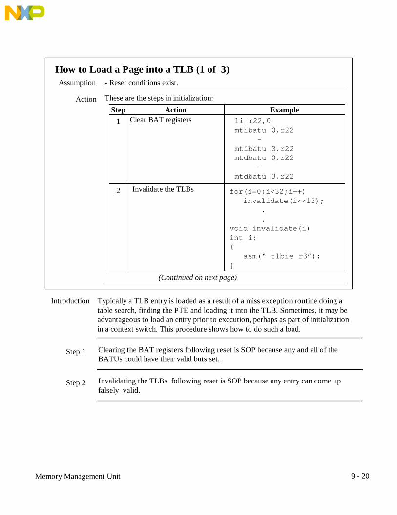
How to Load a Page into a TLB (1 of 3)Assumption - Reset conditions exist.
Action These are the steps in initialization:Step Action Example
1
Invalidate the TLBs2 for(i=0;i<32;i++) invalidate(i<<12); . .void invalidate(i)int i;{ asm(“ tlbie r3”);}
(Continued on next page)
Clear BAT registers li r22,0 mtibatu 0,r22 - mtibatu 3,r22 mtdbatu 0,r22 - mtdbatu 3,r22
Introduction Typically a TLB entry is loaded as a result of a miss exception routine doing atable search, finding the PTE and loading it into the TLB. Sometimes, it may beadvantageous to load an entry prior to execution, perhaps as part of initializationin a context switch. This procedure shows how to do such a load.
Step 1 Clearing the BAT registers following reset is SOP because any and all of theBATUs could have their valid buts set.
Step 2 Invalidating the TLBs following reset is SOP because any entry can come upfalsely valid.

Memory Management Unit 9 - 21
How to Load a Page into a TLB (2 of 3)
ActionStep Action Example
Init DCMP with PTEU lis r22,0x8045 ori r22,r22,0x0009 mtspr 977,r22
3
Init RPA with PTEL4 lis r22,0x9876 ori r22,r22,0x0002 mtspr 982,r22
(Continued on next page)
(5-37)
V: valid bitVSID:virtual segment IDH: hash bitAPI:upper 6 bits, page index
RPN:real page numberR:reference bitC:change bitWIMG:attributesPP:page protection
(5-38)
1. Next, DCMP (or ICMP) must be initialized with the desired PTEU word.2. Then RPA must be initialized with the required PTEL word.

Memory Management Unit 9 - 22
How to Load a Page into a TLB (3 of 3)
ActionStep Action Example
Do a TLB load lis r22,0x1234 ori r22,r22,0x5678 tlbli r22
5
Enable MMU6 mfmsr r22 ori r22,r22,0x30 mtmsr r22 isync
(2-47)
ea: effective address
1. Step 5, the tlb load instruction must be executed. The operand is the desired effective address.2. Finally, the MMU must be enabled.3. Let’s take a look at an example.

Memory Management Unit 9 - 23
Example - Loading a Page into a TLB (1 of 4)
/* THIS PROGRAM CHECKS THE USE OF THE tlbld INSTRUC- *//* TION. THIS INSTRUCTION AND tlbli ARE USEFUL IN *//* LOADING TLB ENTRIES DIRECTLY RATHER THAN GOING THRU*//* EXCEPTION PROCESSING. THE PROGRAM FIRST INITIALIZES*//* A TLB ENTRY AND SUCCESSFULLY WRITES TO THE LOCA- *//* TION. IT THEN INVALIDATES THE ENTRY, AND TRIES TO *//* WRITE TO THE LOCATION AGAIN, BUT NOW A DATA STORE *//* TRANSLATION EXCEPTION OCCURS. *//* IMPORTANT PARAMETERS ARE: *//* PTEU=0x80001000,PTEL=0x22082, EFFECTIVE ADDRESS IS *//* 0x24xxx, REAL ADDRESS IS 0x22xxx. */
main(){ int *tptr; /* TEST POINTER */ void invbat(); /* DECLARE INVBAT FUNCTION */ void invalidate(); /* DECLARE INVALIDATE FUNC */ int i; /* GENERAL VARIABLE */

Memory Management Unit 9 - 24
Example - Loading a Page into a TLB (2 of 4) invbat(); /* INVALIDATE BAT REGS */ for(i = 0; i < 32; i++) /* INVALIDATE THE TLBS */ invalidate(i<<12); initDCMP(0x80001000); /* INIT DCMP WITH PTEU */ initRPA(0x22082); /* INIT RPA WITH PTEL */ filldataentry(0x24000); /* INIT TLB ENTRY FOR EA */ tptr = (int *) 0x22100; /* CLEAR TEST LOCATION */ *tptr = 0; asm(" mfmsr r22"); /* ENABLE DATA MMU */ asm(" ori r22,r22,0x10"); asm(" mtmsr r22"); asm(" isync"); asm(" li r22,0x20"); /*INIT TASK 2,SEG 0,NO PROT */ asm(" mtsr sr0,r22"); tptr = (int *) 0x24100; /* ACCESS PAGE */ *tptr = 0x12345678; invalidate(0x24100); *tptr = 0x9ABCDEF0; /* ACCESS PAGE */}

Memory Management Unit 9 - 25
Example - Loading a Page into a TLB (3 of 4)
void invbat(){ asm(" li r22,0"); /* INVALIDATE BAT REGS */ asm(" mtibatu 0,r22"); asm(" mtibatu 1,r22"); asm(" mtibatu 2,r22"); asm(" mtibatu 3,r22");// asm(" mtdbatu 0,r22"); asm(" mtdbatu 1,r22"); asm(" mtdbatu 2,r22"); asm(" mtdbatu 3,r22");}
void invalidate(i)int i;{ asm(" tlbie r3"); /* INV TLB ENTRY FOR EA IN r3*/}

Memory Management Unit 9 - 26
Example - Loading a Page into a TLB (4 of 4)
initDCMP(pteu)int pteu;{ asm(" mtspr 977,r3"); /* 1ST WORD OF PTE TO DCMP */}
initRPA(ptel)int ptel;{ asm(" mtspr 982,r3"); /* 2ND WORD OF PTE TO RPA */}
filldataentry(ea)int ea;{ asm(" tlbld r3"); /* LOAD DATA TLB ENTRY */}

Memory Management Unit 9 - 27
How an Effective Address is TranslatedThe diagram below shows the flow in determining how an address willbe translated.
Introduction
FlowDiagram
Start
Effective address asserted
MSR[xR] = ? Direct Address Translation0
BAT array hit? Y Protection match? N xSI Exception
x = D or I
YReal address asserted
NGenerate virtual address
xTLB hit? Y
NDo table search PTE found?
Load xTLBY
N
* BAT and pagetranslation are actuallystarted in parallel. If aBAT hit occurs, pagetranslation is terminated.
*
1
1. The translation process begins with the assertion of an effective address. If the associatedMMU, instruction or data, is not enabled, then memory is accessed directly.2. If it is enabled, then BAT and page translation are begun.3. If a BAT hit occurs, page translation is terminated, and a check is made for protectioncompatibility. If there is no compatibility, an xSI exception is taken.4. If a BAT miss occurs, translation continues with the generation of a virtual address. TheMMU then checks for a TLB hit. If there is a hit, a check is made for protection compatibility. Ifthere is no compatibility, an xSI exception is taken.5. If there is no hit, a table search is executed. If the page table entry is found, it is loaded in theTLB and then a hit occurs. If no PTE is found, execution goes to the xSI vector via a branch.6. This is the overall picture. Next, we want to learn what virtual address generation is.

Memory Management Unit 9 - 28
How a Virtual Address is GeneratedThe diagram below shows the flow in determining how a virtual addressis generated.
Introduction
FlowDiagram
Page Index Byte Offset0 3 4 19 20 31
Effective Address
SegmentSelection
Protection match? N xSI Exception
YReal address asserted
xTLB hit? Y
N Do table search PTE found?
Load xTLB
xSI Exception
Y
N
Becomes least significant 12 bits of real address
VirtualAddressGeneration
xTLB miss exception occurs
1. A virtual address is generated by combining the page index, bits 4-19 of the effective address,and the segment selection.2. Next, what is segment selection?

Memory Management Unit 9 - 29
What is Virtual Memory?Virtual memory refers to the ability of the 603e MMU to allocate 4gigabytes of memory for to up to a million tasks.
Definition
603evVirtual
MemoryMap
Task 04 gbytesTask 1
4 gbytes
Task 220-14 gbytes
Task 220-24 gbytes
VirtualMemory
• At any point in time, only one task can be running; therefore, only one 4gbyte memory space is in use.• The pages of a particular task may reside in physical memory or on disk orboth.• When a page that is needed is on disk, the OS must move it into memory.
Comments
1. First of all, let’s review the meaning of virtual memory on the 603ev.2. Virtual memory consists of 1 million 4 gigabyte memory spaces each assigned to a specifictask number.3. Since there is only one 4 gigabyte memory available, it’s apparent that if all tasks are inphysical memory at once, then probably there are few tasks in the system.4. Virtual memory operation allows that some pages can be in memory and some on disk.

Memory Management Unit 9 - 30
How a Segment is Selected (1 of 2)The diagram below shows the flow in determining how a segment isselected.
Introduction
FlowDiagram
Task 04 gbytesTask 1
4 gbytes
Task 220-14 gbytes
Task 220-24 gbytes
Effective Address
SR0SR1
0:3
SR14SR15
1
2
0123456789
101112131415
3
SegmentRegisters
Task VM
SelectedTask VM,
4 gbyte
4
SelectedSegment,256 mbyte
5
The virtual segment ID from the Segment Register determines the selected4 gbyte space and further, determines the segment within that space.
1. Segment selection begins with bits 0-3 of the effective address being used to select one of 16segment registers.2. The segment register, among other things, contains the task ID which selects 1 of 1 millionvirtual memory spaces.3. The virtual memory space is divided into 16 memory segments, 256Mbytes each.4. The segment register also contains a segment number which selects one of the sixteensegments.5. This segment selection then becomes part of the virtual address.

Memory Management Unit 9 - 31
How a Segment is Selected (2 of 2)Segment
Translation 0 4 19 20Page Index Byte Offset
3Effective Address
Task ID Seg No.Protection
Task ID Seg. No.Protection
Virtual Segment ID
0
15
Protection
T KS KP N
0 1 2 3 Prot.Bit Description
T Must always be 0KS Supervisor state protection key
KP User state protection keyN No-execute protection bit
• Two sets of segment registers: one for data and a shadow set for instructionaccesses
8 27 28 31
P. 7-35
1. The segment register consists basically of three fields: protection, task ID, and segmentnumber.2. It is the job of the operating system to program the segment registers on a task switch. At thistime it will put the task number in a least one segment register.3. It puts the number of a segment to be used in the segment register. If the task is using onlyone segment register, the segment number could be any number 0-15. If the task is using all thesegment registers, then the segment number field might contain the number of the segmentregister.4. There are four protection bits: T, KS, KP, and N.5. T must always be zero. If it is one, execution gets directed to a feature that is no longerimplemented on PowerPC.6. There are two protection keys, one for supervisor and one for user.7. N can specify that a segment be used for data only. In this case the shadow instruction registeris disabled.

Memory Management Unit 9 - 32
What is the 603e Page Table Search?The 603e page table search is the process of searching through a hashedtable of page entries for a match to a requested effective address.
Definition
PageTable
Structure
PTE0 PTE1 PTE2 PTE3 PTE4 PTE5 PTE6 PTE7 PTEG0PTE0 PTE1 PTE2 PTE3 PTE4 PTE5 PTE6 PTE7PTE0 PTE1 PTE2 PTE3 PTE4 PTE5 PTE6 PTE7PTE0 PTE1 PTE2 PTE3 PTE4 PTE5 PTE6 PTE7PTE0 PTE1 PTE2 PTE3 PTE4 PTE5 PTE6 PTE7
PTE0 PTE1 PTE2 PTE3 PTE4 PTE5 PTE6 PTE7PTE0 PTE1 PTE2 PTE3 PTE4 PTE5 PTE6 PTE7PTE0 PTE1 PTE2 PTE3 PTE4 PTE5 PTE6 PTE7PTE0 PTE1 PTE2 PTE3 PTE4 PTE5 PTE6 PTE7PTE0 PTE1 PTE2 PTE3 PTE4 PTE5 PTE6 PTE7 PTEGn
SDR1Hash
Primary
HashSecondary
HP = ((EA>>12) & 0xFFFF) ^ (getSRn() & 0x7FFFF);HS = ~HP;PTEGptr = (int *) 0;PTEGptr = (int *)((getSDR1() & 0xFE000000) + (((HP>>10) & (getSDR1() & 0x1FF)) | (setSDR1() & (0x1FF<<16)) + ((HP & 0x3FF)<<6)));
Calculations
1. Here we define a page table search.2. The page table is in memory at a location specified by the register, SDR1 (by the way, there isno other register SDRn except SDR1).3. A page table entry (PTE) is located in one of two page table groups (PTEG) which is selectedby one of two hash functions, primary and secondary.4. The calculations for the hash functions and the PTEGs are shown.

Memory Management Unit 9 - 33
Page Programming Model (1 of 3)
HTABORG
SDR1 - Storage Description Register P. 7-500 1 2 3 4 5 6 7 8 9 10 11 12 13 14 15
16 17 18 19 20 21 22 23 24 25 26 27 28 29 30 31HTABMASK0 0 0 0 0 0 0
VSID
PTEU - Page Table Entry Upper P. 7-370 1 2 3 4 5 6 7 8 9 10 11 12 13 14 15
16 17 18 19 20 21 22 23 24 25 26 27 28 29 30 31APIVSID
RPN
PTEL - Page Table Entry Lower P. 7-370 1 2 3 4 5 6 7 8 9 10 11 12 13 14 15
16 17 18 19 20 21 22 23 24 25 26 27 28 29 30 31WIMGRPN 0 0 0
H
R C PP0
V
1. The next three pages are the programming model for page translation.2. SDR1 contains an originating address (HTABORG) for the page table and a mask field(HTABMASK) to specify the length.3. The PTE consists of two fields: the upper word, PTEU, and the lower word, PTEL.4. PTEU contains the virtual system ID from the segment register. It also contains the field APIwhich is the most significant six bits of the page index field of the effective address. The H bitindicates whether this is a hash primary or hash secondary PTE.5. PTEL contains the real page number and the protection bits, WIMG and PP. In addition, the Rbit is used to record that this page has been accessed and the C bit, that this page has beenchanged.
Memory Management Unit 9 - 34
Page Programming Model (2 of 3)
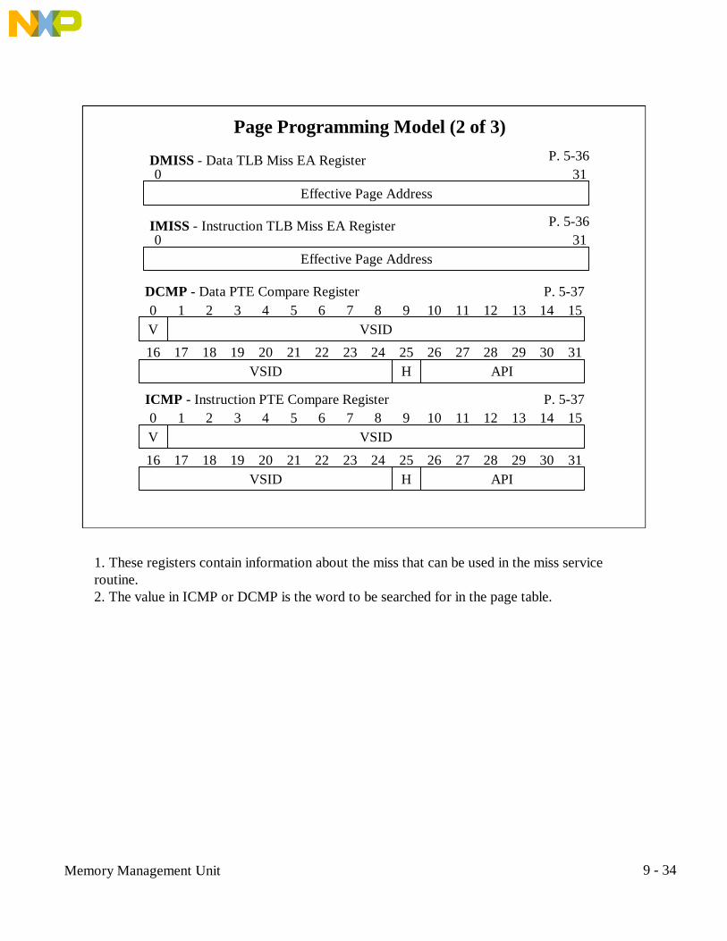
Effective Page Address
DMISS - Data TLB Miss EA Register P. 5-360 31
Effective Page Address
IMISS - Instruction TLB Miss EA Register P. 5-360 31
VSID
DCMP - Data PTE Compare Register P. 5-370 1 2 3 4 5 6 7 8 9 10 11 12 13 14 15
16 17 18 19 20 21 22 23 24 25 26 27 28 29 30 31APIVSID H
V
VSID
ICMP - Instruction PTE Compare Register P. 5-370 1 2 3 4 5 6 7 8 9 10 11 12 13 14 15
16 17 18 19 20 21 22 23 24 25 26 27 28 29 30 31APIVSID H
V
1. These registers contain information about the miss that can be used in the miss serviceroutine.2. The value in ICMP or DCMP is the word to be searched for in the page table.

Memory Management Unit 9 - 35
0
Page Programming Model (3 of 3)
Hashed Page Address
HASH1 - Primary PTEG Address P. 5-370 1 2 3 4 5 6 7 8 9 10 11 12 13 14 15
16 17 18 19 20 21 22 23 24 25 26 27 28 29 30 31Hashed Page Address
HTABORG
0 0 0 0 0
0
Hashed Page Address
HASH2 - Secondary PTEG Address P. 5-370 1 2 3 4 5 6 7 8 9 10 11 12 13 14 15
16 17 18 19 20 21 22 23 24 25 26 27 28 29 30 31Hashed Page Address
HTABORG
0 0 0 0 0
RPN
RPA - Required Physical Address Register P. 5-380 1 2 3 4 5 6 7 8 9 10 11 12 13 14 15
16 17 18 19 20 21 22 23 24 25 26 27 28 29 30 31WIMGRPN 0 0 0 R C PP0
1. The hash registers are used by the miss routine as pointers to where the search should begin.2. Once the PTE has been found, PTE1 of the PTE can be moved to RPA and the search iscomplete.

Memory Management Unit 9 - 36
How the Page Table is Searched? (1 of 2)
FlowDiagram
The diagram below shows the flow in searching the page table.Introduction
Start
TLB miss exception occurs
Get primary hash address from HASH1
Init variable n to 0
PTEUn = xCMP? Increment n
YWrite PTELn to RPA
PTEn[R]=0? Y Set PTEn[R] = 1
EndN
1. PTEUn is the upper word of page table entry n at the PTEG address.2. PTELn is the lower word.
N n < 8?
NA
Y
1. The table is searched as shown. After the miss exception occurs, the service routine uses thepointer in HASH1, which points to the right PTEG, to begin the search.2. The service routine searches through PTEs until it either finds a match or it has searched all 8entries in the PTEG.3. If a match was found, then PTE1 is written to RPA and the R bit is updated.4. If a match was not found, then a second search is started.

Memory Management Unit 9 - 37
How the Page Table is Searched? (2 of 2)
FlowDiagram(cont’d)
Get secondary hash address from HASH2
Init variable n to 0
PTEUn = xCMP?
YWrite PTELn to RPA
PTEn[R]=0? Y Set PTEn[R] = 1
EndN
1. PTEUn is the upper word of page table entry n at the PTEG address.2. PTELn is the lower word.
A
xSI Exception
Increment n N n < 8?
N
YN
1. The second search is done in the same way, except it uses HASH2.2. If a match is not found in this search, it is an error, and execution goes to the xSI exceptionvector via a branch.

Memory Management Unit 9 - 38
How to Assign Page Protection (1 of 2)Notation S:U = Supervisor:User
R/W:R/O = Supervisor access is R/W:User access is R/O
If a page is tohave this
protection...
… then thepage
protection must be...
… and PP in the PTE must be...
R/W:R/Wor
R/O:R/O
KS = N/Aand
KP = N/A
10 for R/W:R/Wand
11 for R/O:R/OR/W:No access
orR/W:R/O
KS = 0and
KP = 1
00 for R/W:No accessand
01 for R/W:R/ONo access:R/W
orR/O:R/W
KS = 1and
KP = 0
00 for No access:R/Wand
01 for R/O:R/WNo access:No access
orR/O:R/O
KS = 1and
KP = 1
00 for No access:No accessand
01 for R/O:R/O
ReferenceTable
1. Here we can learn to assign the protection to a page that we desire. Once again, check thenotation we use. A protection pair consists of protection in the supervisor mode, followed by acolon, followed by protection in the user mode.2. So in the left hand column, we find the protection that we would like to give a particularblock, and then use the other two columns to tell us what values go into the valid bits and the PPfield.3. For example, for a page in which we would like supervisor no access and user read/write, wewould assigned 1 to KS, 0 to KP, and 00 to PP.

Memory Management Unit 9 - 39
How to Assign Page Protection (2 of 2)Example A segment is to have three valid pages as follows: page 1 is to be R/W:R/W,
page 2 is to be R/W:R/O, and page 3 is to be No access:R/W. Fill in therequired protection values in the table below.
PageKS KP PP
10 1 10
2 01
3 *
* Page 3 must be located in another segment.
Exercise A segment is to have two valid pages as follows: page 1 is to be Noaccess:R/W, and page 2 is to be R/W:R/W. Fill in the required protectionvalues in the table below.
PageKS KP PP
1
2
1. In the example, page 1 is to be R/W:R/W. Looking at the table on the previous page, we seethis requires only that the PP bits be 10.2. Page 2 is to be R/W:R/O. Again, according to the previous table, KS must be zero, KP must beone, and PP must be 01.3. Finally, page 3 is to be No Access:R/W. This requires KS to be 1, KP to be zero; therefore, thispage must go in another segment.4. Try the exercise to check your understanding.

Memory Management Unit 9 - 40
What are the TLB Miss Exceptions? (1 of 2)Definition If a valid PTE is not found in the TLB, a TLB miss exception occurs. Software
must then find and load the PTE into the TLB. Additional registers providesome hardware assist.
Types ofMiss
Interrupts
When execution begins at the service routine, the following registerscontain useful information:
TypeInstruction TLB MissData Load TLB Miss
Data Store Translation Miss or C=0
Vector0x10000x11000x1200
123
• Exception type 2 occurs if a data load address cannot be translated by theDTLB• Exception type 3 occurs if:
1. A data store address cannot be translated by the DTLB or2. The C bit must be changed.
HardwareAssist
Registers • D,IMISS = EA that caused the miss• HASH1 = primary PTEG address; HASH2 = secondary PTEG address• D,ICMP = word to be compared against first word of PTEs• RPA = ISR loads with second word of matching PTE

Memory Management Unit 9 - 41
What are the TLB Miss Exceptions? (2 of 2)• When execution begins at the service routine, MSR[TGPR] = 1 and four,32-bit, temporary registers, GPR0-3, are available.• If an access of GPR4-31 is attempted while MSR[TGPR] = 1, results areundefined.
TemporaryScratch
Registers
• When execution begins at the service routine, CR0 has been saved inSRR1[0:3].• The ISR must restore CR0 from SRR1[0:3] before executing rfi.
CR0
. .mfspr r3,srr1mtcrf 0x80,r3rfi
ServiceRoutines
The programs for the TLB miss exception service routines are in the 603UM,p. 5-44.

Memory Management Unit 9 - 42
What are the MMU Error Exceptions?Definition An MMU error exception occurs if a page search results in: 1) no PTE was
found or 2) the protection associated with the PTE is not compatible.
DataStorage
Interrupt(DSI)
• Occurs for an error due to a data access• Uses exception vector 0x300• Error information can be found in:
SRR0 - effective address that caused the exceptionSRR1 - copy of MSRDSISR - protection violation and read/write statusDAR - effective address of protected memory byte
InstructionStorage
Interrupt(ISI)
• Occurs for an error due to an instruction access• Uses exception vector 0x400• Error information can be found in:
SRR0 - effective address of the next instructionSRR1 - copy of MSR; bit 4 indicates a protection violation

Memory Management Unit 9 - 43
How to Initialize a Page Table Entry (1 of 2)Assumption - The segment registers and SDR1 have been initialized.
- The page table has been cleared.- The TLBs have been invalidated.
Action These are the steps in initialization:Step Action Example
Calculate the primary hashfunction
See earlier page1
Calculate the pointer tothe PTEG
3 See earlier page
(Continued on next page)
Calculate the secondaryhash function
hs = ~hp;2
Search the primary PTEGfor an unused entry
4 while(((PTEPptr->PTEU<0) && (i++ < 8)) PTEGptr++;

Memory Management Unit 9 - 44
How to Initialize a Page Table Entry (2 of 2)
ActionStep Action Example
If no available entry inprimary PTEG, thensearch secondary PTEG
5
Initialize the entry with thenew page
PTEGptr->PTEU = pteu; PTEGptr->PTEL = ptel;
6
Execute sync asm(“ sync”);7

Memory Management Unit 9 - 45
Exercise - Initializing a Page Table Entry (1 of 9)
/* THIS PROGRAM GENERATES A PAGE TABLE ENTRY AND THEN *//* ACCESSES THE PAGE TO CHECK THE RESULT. SINCE THE *//* SERVICE ROUTINE FOR A DATA MISS IS NOT INCLUDED, *//* WHEN A DATA MISS OCCURS, THE HASHX REGISTER IS *//* CHECKED TO VERIFY IT HAS THE SAME VALUE AS THE LO- *//* CATION OF THE PAGE ENTRY. */
struct PTE { int PTEU; /* FIRST WORD OF PTE */ int PTEL; /* SECOND WORD OF PTE */ };#define FALSE 0#define TRUE 1

Memory Management Unit 9 - 46
Exercise - Initializing a Page Table Entry (2 of 9)
main(){ int *pt; /* PT POINTER FOR CLEAR */ void invbat(); /* DECLARE INVBAT FUNCTION */ void invalidate(); /* DECLARE INVALIDATE FUNC */ int i; /* GENERAL VARIABLE */
invbat(); /* INVALIDATE BAT REGS */ asm(" lis r22,0"); /* INIT SR0 */ asm(" ori r22,r22,0x20"); /* TASK 2,SEG 0, NO PROT */ asm(" mtsr SR0,r22"); asm(" lis r22,0x3"); /* INIT SDR1 */ asm(" mtsdr1 r22"); /* LOCATE PT AT 0x30000 */ pt = (int *) 0x30000; /* INIT PNTR TO PAGE TABLE */ for(i = 0; i < _____; i++) /* CLEAR PT */ *pt++ = 0; for(i = 0; i < 32; i++) invalidate(i<<12);

Memory Management Unit 9 - 47
Exercise - Initializing a Page Table Entry (3 of 9)
add_a_page(0x24000,0x80001000,0x00022082); /*ADD A PAGE,EA=0x24000, */ /*RA=0x22000,TASK 2,SEG 0 */ pt = (int *) 0x22100; /* CLEAR TEST LOCATION */ *pt = 0; asm(" mfmsr r22"); /* ENABLE DATA MMU */ asm(" ori r22,r22,____"); asm(" mtmsr r22"); asm(" isync"); pt = (int *) 0x24100; /* ACCESS PAGE */ *pt = 0x12345678; remove_a_page(0x24000,0x80001000,0x00022082); /* REMOVE PAGE */ *pt = 0x9ABCDEF0; /* ACCESS PAGE */}

Memory Management Unit 9 - 48
Exercise - Initializing a Page Table Entry (4 of 9)
void invbat(){ asm(" li r22,0"); /* INVALIDATE BAT REGS */ asm(" mtibatu 0,r22"); asm(" mtibatu 1,r22"); asm(" mtibatu 2,r22"); asm(" mtibatu 3,r22");// asm(" mtdbatu 0,r22"); asm(" mtdbatu 1,r22"); asm(" mtdbatu 2,r22"); asm(" mtdbatu 3,r22");}
void invalidate(i)int i;{ asm(" _____ r3");}

Memory Management Unit 9 - 49
Exercise - Initializing a Page Table Entry (5 of 9)
add_a_page(ea,pteu,ptel)int ea,pteu,ptel;{ int hp,hs; /* PRIMARY AND SECONDARY HASH */ struct PTE *PTEGptr; /* POINTER TO PTEG GROUP */ int i; /* GENERAL VARIABLE */
hp = ((ea>>12) & 0xFFFF) ^ (getSR0() & 0x7FFFF); /* DETERMIN PRIMARY HASH VALUE*/ hs = ___; /* DETRMN SECONDARY HASH VALUE*/ PTEGptr = (struct PTE *) 0; /* INIT POINTER TO ZERO*/ PTEGptr = (struct PTE *)((getSDR1() & 0xFE000000) + (((hp>>10) & (getSDR1() & 0x1FF)) | (getSDR1() & (0x1FF<<16)) + ((hp & 0x3FF)<<6))); i = 0; while((PTEGptr->PTEU < 0) && (i++ < 8)) PTEGptr++;

Memory Management Unit 9 - 50
Exercise - Initializing a Page Table Entry (6 of 9)
if(PTEGptr->PTEU < 0) { pteu |= 0x________; PTEGptr = (struct PTE *)((getSDR1() & 0xFE000000) + ((( hs>>10) & (getSDR1() & 0x1FF)) | (getSDR1() & (0x1FF<<16)) + (( hs & 0x3FF)<<6))); i = 0; while((PTEGptr->PTEU < 0) && (i++ < 8)) PTEGptr++; } if(PTEGptr->PTEU >= 0) { PTEGptr->PTEU = pteu; PTEGptr->PTEL = ptel; asm(“ sync”); return(0); } else return(1);}

Memory Management Unit 9 - 51
Exercise - Initializing a Page Table Entry (7 of 9)
remove_a_page(ea,pteu,ptel)int ea,pteu,ptel;{ int hp,hs; /* PRIMARY AND SECONDARY HASH */ struct PTE *PTEGptr; /* POINTER TO PTEG GROUP */ int i; /* GENERAL VARIABLE */ char found; /* BOOLEAN FLAG */
hp = ((ea>>12) & 0xFFFF) ^ (getSR0() & 0x7FFFF); /* DETERMIN PRIMARY HASH VALUE*/ hs = ~hp; /* DETRMN SECONDARY HASH VALUE*/ PTEGptr = (struct PTE *) 0; /* INIT POINTER TO ZERO*/ PTEGptr = (struct PTE *)((getSDR1() & 0xFE000000) + (((hp>>10) & (getSDR1() & 0x1FF)) | (getSDR1() & (0x1FF<<16)) + ((hp & 0x3FF)<<6))); i = 0; found = FALSE;

Memory Management Unit 9 - 52
Exercise - Initializing a Page Table Entry (8 of 9)
do if(PTEGptr->PTEU == pteu && PTEGptr->PTEL == ptel) found = TRUE; while (found == FALSE && i++ < 8); if(found == FALSE) { pteu |= 0x00000040; PTEGptr = (struct PTE *)((getSDR1() & 0xFE000000) + ((( hs>>10) & (getSDR1() & 0x1FF)) | (getSDR1() & (0x1FF<<16)) + (( hs & 0x3FF)<<6))); i = 0; do if(PTEGptr->PTEU == pteu && PTEGptr->PTEL == ptel) found = TRUE; while (found == FALSE && i++ < 8); }

Memory Management Unit 9 - 53
Exercise - Initializing a Page Table Entry (9 of 9)
if(found == TRUE) { PTEGptr->PTEU = 0; asm(“ sync”); return(0); } else return(1);}
getSDR1(){ asm(" mfsdr1 r3");}
getSR0(){ asm(" mfsr r3,0");}

Memory Management Unit 9 - 54
Example - Configuring the MMU for a System (1 of 4)ExamplePhysicalMemory
Map
This is an example of a mix of different devices and the address range fromwhich they are accessed.
Address Space0x00000000 - 0x03FFFFFF0x04000000 - 0x041FFFFF0x04200000 - 0x045FFFFF0x04700000 - 0x04700FFF0x04900000 - 0x04900FFF0x05000000 - 0x0500FFFF0xFE000000 - 0xFFFFFFFF
Board config regs
Device Type
ATM PHYPQ2 internal spaceFlash ROM
SDRAMSRAMSDRAM - local bus
1234567
Function ASEVT in ROM 7EVT in RAM 1Internal memory map 6ATM PHY device 5Board control & status 4FCC BDs & buffers 3
Function ASAll other comm dev buffers 1System stack 2
System program area 1
MMU page table 2System scratchpad 2
FunctionMemory
AreaAssignment
Size64M2M4M4K4K
64K16M
MCC BDs & buffers 3User program area 1User data area 1

Memory Management Unit 9 - 55
Example - Configuring the MMU for a System (2 of 4)
Function ASEVT in ROM 7EVT in RAM 1Internal memory map 6ATM PHY device 5Board control & status 4FCC BDs & buffers 3MCC BDs & buffers 3All other comm dev buffers 1System stack 2
AttributeAssignment W I M G Pr
Instruction
0 0 0 0 R/O:NAW I M G Pr
Data
0 1 0 0 R/O:NA0 0 0 0 R/O:R/O 0 1 0 0 R/W:R/W0 1 0 0 NA:NA 0 1 0 0 R/W:NA0 1 0 0 NA:NA 0 1 0 1 R/W:NA0 1 0 0 NA:NA 0 1 0 1 R/W:NA0 1 0 0 NA:NA 0 1 0 0 R/W:R/W0 1 0 0 NA:NA 0 1 0 0 R/W:R/W
System program area 1
MMU page table 2System scratchpad 2
User program area 1User data area 1
0 1 0 0 NA:NA 0 0 0 0 R/W:R/W0 1 0 0 NA:NA 0 1 0 0 R/W:NA0 1 0 0 NA:NA 0 1 0 0 R/W:NA0 1 0 0 NA:NA 1 0 0 0 R/W:NA0 0 0 0 R/O:NA 0 1 0 0 NA:NA0 0 0 0 R/O:R/O 0 1 0 0 NA:NA0 0 0 0 NA:NA 1 0 0 0 R/W:R/W

Memory Management Unit 9 - 56
Example - Configuring the MMU for a System (3 of 4)
Function ASEVT in RAM 1
Board control & status 4
Sortingby
AddressSpace
W I M G PrInstruction
W I M G PrData
EVT in ROM 7 0 0 0 0 R/O:NA 0 1 0 0 R/O:NA
0 0 0 0 R/O:R/O 0 1 0 0 R/W:R/W
Internal memory map 6 0 1 0 0 NA:NA 0 1 0 0 R/W:NAATM PHY device 5 0 1 0 0 NA:NA 0 1 0 1 R/W:NA
0 1 0 0 NA:NA 0 1 0 1 R/W:NA
FCC BDs & buffers 3MCC BDs & buffers 3
0 1 0 0 NA:NA 0 1 0 0 R/W:R/W0 1 0 0 NA:NA 0 1 0 0 R/W:R/W
All other comm dev buffers 1 0 1 0 0 NA:NA 0 1 0 0 R/W:R/W
System stack 2MMU page table 2System scratchpad 2
0 1 0 0 NA:NA 0 1 0 0 R/W:NA0 1 0 0 NA:NA 0 1 0 0 R/W:NA0 1 0 0 NA:NA 1 0 0 0 R/W:NA
System program area 1User program area 1User data area 1
0 0 0 0 R/O:NA 0 1 0 0 NA:NA0 0 0 0 R/O:R/O 0 1 0 0 NA:NA0 0 0 0 NA:NA 1 0 0 0 R/W:R/W
• AS3 & 7 can be block address translation.• The system program area and all other commdev buffers can also be blocks.

Memory Management Unit 9 - 57
Example - Configuring the MMU for a System (4 of 4)
FunctionEVT in RAM
Board control & status
Sortingby
AddressSpace
EVT in ROMInternal memory mapATM PHY device
FCC BDs & buffersMCC BDs & buffers
All other comm dev buffers
System stackMMU page tableSystem scratchpad
System program areaUser program areaUser data area
• AS3 & 7 can be block address translation.• The system program area and all other commdev buffers can also be blocks.
AS
1
2
3
4567
0x00000000 - 0x003FFFFF0x00400000 - 0x007FFFFF0x00800000 - 0x00BFFFFF0x00C00000 - 0x02FFFFFF0x03000000 - 0x03FFFFFF0x04000000 - 0x0407FFFF0x04080000 - 0x040FFFFF0x04100000 - 0x041FFFFF0x04200000 - 0x044FFFFF0x04500000 - 0x045FFFFF0x04700000 - 0x04700FFF0x04900000 - 0x04900FFF0x05000000 - 0x0500FFFF0xFE000000 - 0xFFFFFFFF
Address

Memory Management Unit 9 - 58
How to Initialize the MMU (1 of 4)Assumption - Reset conditions exist.
Action These are the steps in initialization:Step Action Example
Clear BAT registers li r22,0 mtibatu 0,r22 - mtibatu 3,r22 mtdbatu 0,r22 - mtdbatu 3,r22
1
Init lower BAT registerBRPN:real page addr[0:14]WIMG:attribute bitsPP:access protection
(7-25)
2 lis r22,0xFFFC ori r22,r22,3 mtibatl 0,r22
(Continued on next page)

Memory Management Unit 9 - 59
How to Initialize the MMU (2 of 4)
Action Step Action ExampleInit upper BAT register
BEPI:effective addr[0:14]BL:block lengthVS:privilege mode validVP:problem mode valid
(7-25)
3 lis r22,0xFFFC ori r22,r22,6 mtibatu 0,r22
Repeat steps 2 and 3 foreach required lower-upperpair BAT registers.
4
Initialize SR0-155T: must be 0KS:Supervisor keyKP:User state keyN:no-execute protectionTask ID:task numberSeg No.:segment number
(7-35)
lis r22,0x6000 ori r22,r22,0x0010 mtsr SR0,r22
Also: mtsrin

Memory Management Unit 9 - 60
How to Initialize the MMU (3 of 4)
Action Step Action ExampleInit SDR1HTABORG: PT base addrHTABMASK:PT addr mask
(7-50)
6 lis r22,0xE044 ori r22,r22,1 mtsdr1 r22
Initialize the PT to allinvalid
7
Invalidate the TLBs8 for (i=0; i < 32; i++) invalidate(i<<12); . .void invalidate(i)int i;{ asm(“ tlbie r3”);}

Memory Management Unit 9 - 61
How to Initialize the MMU (4 of 4)
Action Step Action ExampleInitialize PT entries8
Enable the MMU9 asm(“ mfmsr r22”);asm(“ ori r22,r22,0x30”);asm(“ mtmsr r22”);asm(“ isync”);
(7-37)

Memory Management Unit 9 - 62
M
0--0
I
0--0
W
0--0
G
0--0
0000
Allocating the Blocks (1 of 2)
IBATU 0123
BEPI
008------
FE0
BL VS
1001
VP
0000
000 0000 0 01 11 0x0080007E
RegisterHex Value
--- 0000 - -- -- ---- 0000 - -- -- -000 0000 0 0F 11 0xFE0000FE
IBATL 0123
BRPN
008------
FE0
PP
01----11
000 0 0x00800001
RegisterHex Value
--- 0 ---- 0 -000 0 0xFE000003
00000000
0000
Hex numbers
Binary numbers

Memory Management Unit 9 - 63
Allocating the Blocks (2 of 2)
DBATU 0123
BEPI
008004042FE0
BL VS
1111
VP
1110
000 0000 0 01 11 0x0080001F
RegisterHex Value
000 0000 0 01 11 0x0040001E000 0000 0 01 11 0x0420001F000 0000 0 0F 11 0xFE0000FE
M
0000
I
1111
W
0000
G
0000
0000
DBATL 0123
BRPN
008004042FE0
PP
10101011
000 0 0x00800022
RegisterHex Value
000 0 0x00400022000 0 0x04200022000 0 0xFE000023
00000000
0000

Memory Management Unit 9 - 64
Initializing the Segment Registers
SegmentRegister
0123
Task ID
0 00001 0 0x30000010
RegisterHex Value
0 00000 00 000000 00000
T
0000
KS
0111
KP
1000
N
1000
Seg. No.
4567
0 000000 000000 000000 00000
0000
1111
0000
0000
891011
0 000000 000000 000000 00000
0000
1111
0000
0000
12131415
0 000000 000000 000000 00000
0000
1111
0000
0000
000000000000000
00000000000000

Memory Management Unit 9 - 65
Initializing SDR11. Determine total memory size to be allocated in pages.
Size8M-BAT
2M4M4K4K
64K16M
1234567
AS Allocation
PageBATPagePagePageBAT
64M Memory to be allocated in pages = 58M
2. See page 7-52 to determine required page table size.
Required page table size = 512K; therefore,
HTABORG = x xxxx x000 and HTABMASK = 0 0000 0111
SDR1 0408 0 0 0 0 0 07HTABMASKHTABORG
0x04080007Reg Value


![Immediate Insight User's Guide€¦ · application initialized datastore initialized Do you want this server to be part of a cluster [N]? N Installation Complete Type 'sudo reboot'](https://static.fdocuments.in/doc/165x107/5f07c2167e708231d41e9843/immediate-insight-users-guide-application-initialized-datastore-initialized-do.jpg)