Memory Card Camera-Recorder AG-HPX250EJIf the plug contains a removable fuse cover you must ensure...
36
M0811HO0 -FJ ENGLISH VQT3T25 (E) Before use Description of parts Preparation Menu Reference ■ This product is eligible for the P2HD 5 Year Warranty Repair Program. For details, see page E-6. Operating Instructions Vol.1 Memory Card Camera-Recorder Model No. AG-HPX250EJ Note that Operation Instructions Vol. 1 describes basic operations of the Memory Card Camera-Recorder. For instructions on advanced operations of the Memory Card Camera-Recorder, refer to Operating Instructions Vol. 2 (pdf file) contained in the supplied CD-ROM. Volume 1 Before operating this product, please read the instructions carefully and save this manual for future use.
Transcript of Memory Card Camera-Recorder AG-HPX250EJIf the plug contains a removable fuse cover you must ensure...

M0811HO0 -FJ ENGLISH
VQT3T25 (E)
Bef
ore
use
Des
crip
tion
of p
arts
Prep
arat
ion
Men
uR
efer
ence
■ This product is eligible for the P2HD 5 Year Warranty Repair Program. For details, see page E-6. Operating Instructions Vol.1
Memory Card Camera-Recorder
Model No. AG-HPX250EJ
Note that Operation Instructions Vol. 1 describes basic operations of the Memory Card Camera-Recorder.For instructions on advanced operations of the Memory Card Camera-Recorder, refer to Operating Instructions Vol. 2 (pdf file) contained in the supplied CD-ROM.
Volume 1
Before operating this product, please read the instructions carefully and save this manual for future use.

E-1
indicatessafetyinformation.
WARNING:Thisequipmentmustbeearthed.Toensuresafeoperation,thethree-pinplugmustbeinsertedonlyintoastandardthree-pinpowerpointwhichiseffectivelyearthedthroughnormalhouseholdwiring.Extensioncordsusedwiththeequipmentmusthavethreecoresandbecorrectlywiredtoprovideconnectiontotheearth.Wronglywiredextensioncordsareamajorcauseoffatalities.Thefactthattheequipmentoperatessatisfactorilydoesnotimplythatthepowerpointisearthedorthattheinstallationiscompletelysafe.Foryoursafety,ifyouareinanydoubtabouttheeffectiveearthingofthepowerpoint,pleaseconsultaqualifiedelectrician.
WARNING:•Toreducetheriskoffireorelectricshock,donotexposethisequipmenttorainormoisture.
•Toreducetheriskoffireorelectricshockhazard,keepthisequipmentawayfromallliquids.Useandstoreonlyinlocationswhicharenotexposedtotheriskofdrippingorsplashingliquids,anddonotplaceanyliquidcontainersontopoftheequipment.
WARNING:Alwayskeepmemorycards(optionalaccessory)oraccessories(coinbattery,microphoneholderscrews,microphoneholderadapter,INPUTterminalcovers)outofthereachofbabiesandsmallchildren.
CAUTION:Donotremovepanelcoversbyunscrewingthem.Toreducetheriskofelectricshock,donotremovethecovers.Nouserserviceablepartsinside.Referservicingtoqualifiedservicepersonnel.
CAUTION:Toreducetheriskoffireorelectricshockandannoyinginterference,usetherecommendedaccessoriesonly.
CAUTION:Donotjar,swing,orshaketheunitbyitshandle.Anystrongjolttothehandlemaydamagetheunitorresultinpersonalinjury.
CAUTION:Themainsplugofthepowersupplycordshallremainreadilyoperable.TheACreceptacle(mainssocketoutlet)shallbeinstalledneartheequipmentandshallbeeasilyaccessible.TocompletelydisconnectthisequipmentfromtheACmains,disconnectthepowercordplugfromtheACreceptacle.
CAUTION:Dangerofexplosionorfireifbatteryisincorrectlyreplacedormistreated.•Donotdisassemblethebatteryordisposeofitinfire.
•Donotstoreintemperaturesover60°C.•Donotexposethebatterytoexcessiveheatsuchassunshine,fireorthelike.
For Battery Pack•Usespecifiedcharger.•Replaceonlywithsameorspecifiedtype.For Battery of Remote Controller•ReplacebatterywithpartNo.CR2025only.•Donotrechargethebattery.
CAUTION:Inordertomaintainadequateventilation,donotinstallorplacethisunitinabookcase,built-incabinetoranyotherconfinedspace.Topreventriskofelectricshockorfirehazardduetooverheating,ensurethatcurtainsandanyothermaterialsdonotobstructtheventilation.
CAUTION:Donotlifttheunitbyitshandlewhilethetripodisattached.Whenthetripodisattached,itsweightwillalsoaffecttheunit’shandle,possiblycausingthehandletobreakandhurtingtheuser.Tocarrytheunitwhilethetripodisattached,takeholdofthetripod.
CAUTION:Excessivesoundpressurefromearphonesandheadphonescancausehearingloss.
CAUTION:Donotleavetheunitindirectcontactwiththeskinforlongperiodsoftimewheninuse.Lowtemperatureburninjuriesmaybesufferedifthehightemperaturepartsofthisunitareindirectcontactwiththeskinforlongperiodsoftime.Whenusingtheequipmentforlongperiodsoftime,makeuseofthetripod.
Read this first!

E-2
Note:Battery Charger / AC AdaptorTheratingplateisontheundersideoftheBatteryChargerandACAdaptor.DisconnecttheACmainsplugfromtheACmainssocketwhennotinuse.
Read this first! (continued)
indicatessafetyinformation.
CautionforACMainsLeadFor battery charger
FOR YOUR SAFETY PLEASE READ THE FOLLOWING TEXT CAREFULLY.This product is equipped with 2 types of AC mains cable. One is for continental Europe, etc. and the other one is only for U.K.
Appropriatemainscablemustbeusedineachlocalarea,sincetheothertypeofmainscableisnotsuitable.
FOR CONTINENTAL EUROPE, ETC.Not to be used in the U.K.
FOR U.K. ONLY
How to replace the fuse1. Open the fuse compartment with a
screwdriver.
2. Replace the fuse
Fuse
FOR U.K. ONLYThis appliance is supplied with a moulded three pin mains plug for your safety and convenience.A 5 amp fuse is fitted in this plug.Should the fuse need to be replaced please ensure that the replacement fuse has a rating of 5 amps and that it is approved by ASTA or BSI to BS1362.Check for the ASTA mark or the BSI mark on the body of the fuse.
If the plug contains a removable fuse cover you must ensure that it is refitted when the fuse is replaced.If you lose the fuse cover the plug must not be used until a replacement cover is obtained.A replacement fuse cover can be purchased from your local Panasonic Dealer.
EEE Yönetmeliğine Uygundur.EEE Complies with Directive of Turkey.
E-3
Read this first! (continued)
indicatessafetyinformation.
CautionforACMainsLeadFor AC adaptor
FOR YOUR SAFETY PLEASE READ THE FOLLOWING TEXT CAREFULLY.This product is equipped with 2 types of AC mains cable. One is for continental Europe, etc. and the other one is only for U.K.
Appropriatemainscablemustbeusedineachlocalarea,sincetheothertypeofmainscableisnotsuitable.
FOR CONTINENTAL EUROPE, ETC.Not to be used in the U.K.
FOR U.K. ONLY
How to replace the fuse1. Open the fuse compartment with a
screwdriver.
2. Replace the fuse
Fuse
FOR U.K. ONLYThis appliance is supplied with a moulded three pin mains plug for your safety and convenience.A 13 amp fuse is fitted in this plug.Should the fuse need to be replaced please ensure that the replacement fuse has a rating of 13 amps and that it is approved by ASTA or BSI to BS1362.Check for the ASTA mark or the BSI mark on the body of the fuse.
If the plug contains a removable fuse cover you must ensure that it is refitted when the fuse is replaced.If you lose the fuse cover the plug must not be used until a replacement cover is obtained.A replacement fuse cover can be purchased from your local Panasonic Dealer.

E-4
EMC NOTICE FOR THE PURCHASER/USER OF THE APPARATUS1. Applicable standards and operating environment
The apparatus is compliant with:• standardsEN55103-1andEN55103-22009,and•electromagneticenvironmentsE1,E2,E3andE4.
2. Pre-requisite conditions to achieving compliance with the above standards<1> Peripheral equipment to be connected to the apparatus and special connecting cables
•Thepurchaser/userisurgedtouseonlyequipmentwhichhasbeenrecommendedbyusasperipheralequipmenttobeconnectedtotheapparatus.
•Thepurchaser/userisurgedtouseonlytheconnectingcablesdescribedbelow.
<2> For the connecting cables, use shielded cables which suit the intended purpose of the apparatus.•VideosignalconnectingcablesUsedoubleshieldedcoaxialcables,whicharedesignedfor75-ohmtypehigh-frequencyapplications,forSDI(SerialDigitalInterface).Coaxialcables,whicharedesignedfor75-ohmtypehigh-frequencyapplications,arerecommendedforanalogvideosignals.
• AudiosignalconnectingcablesIfyourapparatussupportsAES/EBUserialdigitalaudiosignals,usecablesdesignedforAES/EBU.Useshieldedcables,whichprovidequalityperformanceforhigh-frequencytransmissionapplications,foranalogaudiosignals.
•Otherconnectingcables(IEEE1394,USB)Usedoubleshieldedcables,whichprovidequalityperformanceforhigh-frequencyapplications,asconnectingcables.
•WhenconnectingtotheDVIsignalterminal,useacablewithaferritecore.• Ifyourapparatusissuppliedwithferritecore(s),theymustbeattachedoncable(s)followinginstructionsinthismanual.
3. Performance levelTheperformanceleveloftheapparatusisequivalenttoorbetterthantheperformancelevelrequiredbythesestandards.However,theapparatusmaybeadverselyaffectedbyinterferenceifitisbeingusedinanEMCenvironment,suchasanareawherestrongelectromagneticfieldsaregenerated(bythepresenceofsignaltransmissiontowers,cellularphones,etc.).Inordertominimizetheadverseeffectsoftheinterferenceontheapparatusincaseslikethis,itisrecommendedthatthefollowingstepsbetakenwiththeapparatusbeingaffectedandwithitsoperatingenvironment:
1.Placetheapparatusatadistancefromthesourceoftheinterference.2.Changethedirectionoftheapparatus.3.Changetheconnectionmethodusedfortheapparatus.4.Connecttheapparatustoanotherpoweroutletwherethepowerisnotsharedbyanyotherappliances.
Read this first! (continued)

E-5
Read this first! (continued)
■Batteries that may be used with this product (Correct as of September 2011)PanasonicCGA-D54sbatteriesmaybeusedwiththeAG-HPX250EJ.
Recommendation for Use of Genuine Panasonic Battery (Rechargeable Battery)ThankyouforusingaPanasonicproduct.Ithasbeenfoundthatcounterfeitbatterypackswhichlookverysimilartothegenuineproductaremadeavailabletopurchaseinsomemarkets.Someofthesebatterypacksarenotadequatelyprotectedwithinternalprotectiontomeettherequirementsofappropriatesafetystandards.Thereisapossibilitythatthesebatterypacksmayleadtofireorexplosion.Pleasebeadvisedthatwearenotliableforanyaccidentorfailureoccurringasaresultofuseofacounterfeitbatterypack.ToensurethatsafeproductsareusedwewouldrecommendthatagenuinePanasonicbatterypackisused.•Beawarethatmanybatteriessoldatextremelycheappricesorinsituationswhereitisdifficulttoverifytheactualproductsbeforepurchasehaveproventobecounterfeit.
To remove the battery EU
Battery release button
Main Power Battery(Refer to page E-20 for the detail.)Pressthebatteryreleasebutton.
Back-up Battery•Fortheremovalofthebatteryfordisposalattheendofitsservicelife,pleaseconsultyourdealer.

E-6
Read this first! (continued)
F0407W4029 -FPrinted in Japan VQC6095-3
*1: Please note that this extended warranty is not available in some countries/regions. *2: Not all models eligible for extended warranty coverage. *3: The basic warranty period may vary depending on the country/region. *4: Not all repair work is covered by this extended warranty. *5: The maximum warranty period may be adjusted depending on the number of hours the device has been used.
1st year 2nd year 3rd year 4th year 5th year*5
P2HD device*2 Basic warranty*3 Extended warranty repair*4
Purchase P2 product
Register online within 1 month
“Registration Notice” e-mail sent
Details about user registration and the extended warranty: http://panasonic.biz/sav/pass_e
Free 5 years of Warranty Repairs
Customers who register as users on the website will receive an extended warranty repair valid for up to five years.
P2HD 5 Year Warranty Repair Program*1
Thank you for purchasing this Panasonic P2HD device.Register as a user for this device to receive a special service warranty up to five years of free warranty repairs.
Make sure to save the “Registration Notice” e-mail during the warranty period.
Please note, this is a site that is not maintained by Panasonic Canada Inc. The Panasonic Canada Inc. privacy policy does not apply and is not applicable in relation to any information submitted. This link is provided to you for convenience.
*1: Veuillez noter que cette garantie prolongée n’est pas disponible dans certains pays ou régions. *2: La garantie prolongée n’est pas applicable à certains produits. *3: La période de la garantie de base peut varier en fonction du pays ou de la région. *4: Toutes les réparations ne sont pas couvertes par cette garantie prolongée. *5: La période de garantie maximum peut être ajustée en fonction du nombre d’heures d’utilisation de l’appareil.
1ère année 2ère année 3ère année 4ère année 5ère année*5
Appareil P2HD*2 Garantie de base*3 Réparations couvertes par la garantie prolongée*4
Achat d’un produit P2
Inscription en ligne dans le mois qui suit
Envoi d’un courriel “Registration Notice”
Détails sur l’inscription des utilisateurs et la garantie prolongée: http://panasonic.biz/sav/pass_e
5 années gratuites de réparations couvertes par la garantie
Les clients qui s’inscrivent comme utilisateurs sur le site web bénéficient d’une garantie prolongée valide pendant 5 ans.
Programme de réparations sous garantie pendant 5 ans pour un P2HD*1
Nous vous remercions d’avoir choisi cet appareil Panasonic P2HD.Inscrivez-vous comme utilisateur de cet appareil pour bénéficier d’une garantie spéciale donnant droit à des réparations gratuites couvertes par la garantie pendant une période allant jusqu’à 5 ans.
Prenez soin de conserver le courriel “Registration Notice” pendant toute la période de garantie.
Veuillez noter qu’il ne s’agit pas d’un site tenu à jour par Panasonic Canada Inc. La politique de confidentialité de Panasonic Canada Inc. ne s’y applique pas et n’est pas applicable aux informations soumises. Ce lien vous est offert pour votre convenance.
*1: la garanzia estesa non è disponibile in alcune nazioni/regioni. *2: per alcuni modelli la garanzia estesa non è disponibile. *3: il periodo di validità della garanzia di base può variare a seconda delle nazioni/regioni. *4: non tutti i lavori di riparazione sono coperti dalla garanzia estesa. *5: il periodo massimo di validità della garanzia può variare in base al numero di ore di utilizzo del dispositivo.
1° anno 2° anno 3° anno 4° anno 5° anno*5
Prodotto P2HD*2 Garanzia di base*3 Garanzia estesa per riparazioni*4
Acquisto prodotto P2
Registrazione online entro 1 mese
Invio e-mail “Avviso di registrazione”
Per informazioni dettagliate sulla registrazione degli utenti e sulla garanzia estesa: http://panasonic.biz/sav/pass_e
5 anni di riparazioni in garanzia gratuite
I clienti che si registrano come utenti sul sito Internet riceveranno una garanzia estesa per riparazioni valida fino a cinque anni.
P2HD - Programma di riparazioni in garanzia per 5 anni*1
Grazie per aver acquistato questo prodotto Panasonic P2HD.Registrandosi come utente di questo prodotto, riceverà una garanzia speciale che le permetterà di ottenere riparazioni gratuite in garanzia fino a cinque anni.
Verificare di aver salvato l’e-mail “Avviso di registrazione” durante il periodo di garanzia.

E-7
•SDHCLogoisatrademarkofSD-3C,LLC.•HDMI,theHDMIlogo,andHigh-DefinitionMultimediaInterfacearetrademarksorregisteredtrademarksofHDMILicensingLLC.
•Microsoft®,Windows®,andWindowsVista®areeitherregisteredtrademarksortrademarksofMicrosoftCorporationintheUnitedStatesand/orothercountries.
•ScreenshotsareusedinaccordancewithMicrosoftCorporationguidelines.•Apple®,Macintosh®,andMacOS®aretrademarksofAppleInc.,registeredintheUnitedStatesandothercountries.
•Othermodelnames,companynames,andproductnameslistedintheseoperatinginstructionsaretrademarksorregisteredtrademarksoftheirrespectivecompanies.
•ThisproductislicensedundertheAVCPatentPortfolioLicenseforthepersonalandnon-commercialuseofaconsumer,andnolicenseisgrantedorshallbeimpliedforanyuseotherthanthepersonalusesdetailedbelow.
- ToencodevideoincompliancewiththeAVCstandard(“AVCVideo”)- TodecodeAVCVideothatwasencodedbyaconsumerengagedinapersonalandnon-commercialactivity
- TodecodeAVCVideothatwasobtainedfromavideoproviderlicensedtoprovideAVCVideo AdditionalinformationmaybeobtainedfromMPEGLA,LLC(http://www.mpegla.com).
Note concerning illustrations in these instructions• Illustrations(camera-recorder,menuscreens,etc.)intheseoperatinginstructionsdifferslightlyfromtheactualcamera-recorder.
• Inordertodisplaythepositionofterminalsonthecamera-recorder,theprotectivecapsincludedwiththecamera-recorderarenotnotedexceptin“Descriptionofparts”(PageE-15).
References•Referencesareshownas(Page00).
Terminology•BothSDMemoryCardsandSDHCMemoryCardsasreferredtoas“SDMemoryCards”intheseoperatinginstructions.
•Memorycardsthathavethe“P2”logo(e.g.,AJ-P2C064AG,anoptionalaccessory)arereferredtoas“P2cards”intheseoperatinginstructions.
•Videothatiscreatedduringasinglerecordingoperationisreferredtoasa“clip”intheseoperatinginstructions.

E-8
Outline of operationsThisunitisahandheldP2memorycardcamera-recorderthatachievesthehighqualityimagesprovidedbyfullHDthroughtheincorporationofacam-type22xopticalzoomanda1/3-type2.2-megapixel3MOSsensorinthecameraunit,andincludingAVC-Intra100compressionasstandardintherecordingandplaybackunit.
ThesettingvaluessuchastheuserfilearesavedtoandreadfromtheSDmemorycard.
P2 card
Youcanusethefollowingfeatures:• HD (High Definition) recording• Multi format recording• Variable frame ratesSlow&quickmotionrecording
• Maximum 4 channel uncompressed digital audio recording
• DV recording (480i/576i)Fordetailsonhowtohandlerecordeddata,see(Page158ofVol.2).
1 P2 mode shooting and playback(Page 10 of Vol. 2, Page 74 of Vol. 2)
Personal Computer
The data (file) is transferred for nonlinear editing on your personal computer or other unit.
2 USB device mode(Page 107 of Vol. 2)
External hard disk
The unit directly controls the external hard disk drive, and transfers the data (file) to it.
3 USB host mode(Page 109 of Vol. 2)
Monitor Video equipment/Television
Personal Computer/ Memory card recorder
Thecontentscanbetransferredasadatastream(digitaldubbing).
AV cable HDMI cable
USB2.0 (HOST)
USB2.0 (DEVICE)
P2 card
DVCPRO/DV(IEEE1394)(Windows/Macintosh)
BNC cable(HDSDI)

E-9
Contents
Read this first! ................................................. E-1Outline of operations ...................................... E-8
Before useOperating precautions .................................. E-11Precaution for use ......................................... E-13Accessories ................................................... E-14Optional units ................................................ E-14
Description of partsDescription of parts ....................................... E-15Leftside....................................................... E-15Topandrightside........................................ E-16Frontandrearside...................................... E-17Remotecontrol............................................ E-18
PreparationCharging the battery ..................................... E-19Charging...................................................... E-19
Power sources ............................................... E-20Usingthebattery......................................... E-20UsingtheACadaptor.................................. E-20
Adjusting the hand strap .............................. E-21Attaching the shoulder strap ........................ E-21Detaching and attaching the lens hood ...... E-21Detaching and attaching the lens cap ......... E-22Fitting the eye cup ......................................... E-22The remote control ........................................ E-23Insertthebattery......................................... E-23Remotecontrolsetup.................................. E-23
Turn on/off the camera-recorder .................. E-24Setting the calendar ...................................... E-25Charging the built-in battery ........................ E-26
MenuUsing the setup menus ................................. E-27Usingthemenus......................................... E-27Initializingthemenusettings....................... E-28
Setup menu structure ................................... E-29
ReferenceSpecifications ................................................ E-31
Volume1(ThisBook)

E-10
Volume2(CD)
ShootingViewfinderTally lampBasic shooting operationsUsing SD/SDHC memory cardsUsing the zoom functionShooting in progressive modeRecording with Variable Frame Rate (VFR)Shooting in manual modeAdjusting the white balance and black
balanceShooting techniques for different targetsUsing special recording modesAdjusting the shutter speedSwitching audio inputUsing scene files (Scene File Data)Using time data
PlaybackBasic playback operationsThumbnail operationsUseful playback functions
EditingConnecting external unitsConnections to the DVCPRO/DV
connectorNonlinear editing with P2 card
(PC mode: USB device)Using a hard disk drive
(PC mode: USB host)
DisplaysScreen displays
MenuSetup menu list
ReferenceBefore calling for serviceUpdating the firmware incorporated into
the unitCleaningStorage precautionsHow to handle data recorded on P2 cardsCheckpoints for using memory cardsInformation on software for this productRecording format listIndex

E-11
Do not allow any water to get into the camera-recorder when using it in the rain or snow or at the beach.•Failuretoheedthisprecautionwillcausethecamera-recorderorP2cardtomalfunction(andmayresultinirreparabledamage).
Keep the camera-recorder away from equipment (such as TV sets and video game machines) that generate magnetic fields.•Usingthecamera-recorderontopofornearaTVsetmaycausedistortionintheimagesand/orsoundduetotheelectromagneticwavesthatthesetemits.
•Thepowerfulmagneticfieldsgeneratedbyspeakersorlargemotorsmaydamageyourrecordingsordistorttheimages.
•Theelectromagneticwavesemittedfromamicrocomputerwilladverselyaffectthecamera-recorder,causingtheimagesand/orsoundtobedistorted.
• Ifthecamera-recorderissoadverselyaffectedbyproductsthatgeneratemagneticfieldsthatitnolongeroperatesproperly,turnitoffandremovethebatteryorunplugtheACadaptorfromthepoweroutlet.TheninstallthebatteryagainorreconnecttheACadaptor.Afterthis,turnthecamera-recorderbackon.
Do not use the camera-recorder near radio transmitters or high-voltage equipment.•Usingthecamera-recorderneararadiotransmitterorhigh-voltageequipmentmayadverselyaffecttherecordedimagesand/orsound.
Do not allow any sand or dust to get into the camera-recorder when using it at the beach and other similar places.•Sandanddustcandamagethecamera-recorderoracard.(Beespeciallycarefulwheninsertingorremovingacard.)
Battery charger and battery• IftheCHARGElampcontinuestoblinkevenwhenthebatterytemperatureisnormal,theremaybesomethingwrongwiththebatteryorbatterycharger.Contactyourdealer.
•Thebatterytakeslongertochargewhenitiswarm.
•Thebatterychargercaninterferewithradioreceptionsokeepradiosatleast1mawayfromit.
•Thebatterychargermaymakesomenoisewhenyouareusingit,butthisisnormal.
Take precautions not to drop the camera-recorder when moving it.•Strongimpactsmaydamagethecamera-recorderandcauseittostopworking.
•Handlethecamera-recorderwithcare,usingthehandstraporshoulderstraptocarryit.
Do not spray the camera-recorder with insect sprays or other volatile substances.•Thesecanwarpthecamera-recorderorcausethefinishtocomeoff.
•Donotleavethecamera-recorderincontactwithrubberorPVCproductsforextendedperiodsoftime.
After use, remove the battery and disconnectthe AC power supply cord.
Battery characteristicsThiscamera-recorderusesarechargeablelithiumionbatterythatusesitsinternalchemicalreactiontogenerateelectricalenergy.Thisreactioniseasilyinfluencedbytheambienttemperatureandhumidity,andthebattery’seffectiveoperatingtimeisreducedasthetemperaturerisesorfalls.Inverylowtemperatures,thebatterymaylastabout5minutes.Protectivecircuitryfunctionsifyouusethebatterywhereitisveryhotandyouwillhavetowaitbeforeyoucanuseitagain.
Operating precautions
Before use

E-12
Bef
ore
use
Remove the battery after use.Completelyremovethebattery.(Thebatterycontinuestobeusedevenifyouhaveturnedthecamera-recorderoff.)Thebatterycanoverdischargeifyouleaveitinthecamera-recorderanditmaybecomeimpossibletorechargeit.Donotremovethebatterywhenthepowerison.Ifthebatteryisremoved,makesurethatthepowerisoffandthemodelampcompletelylightsoff.
Keep dust and other foreign objects away from the battery terminal.Ifthebatteryisdropped,makesurethatthebodyandterminalportionofthebatteryarenotdeformed.Ifadeformedbatteryisinsertedintothecamera-recorderorplacedontheACadaptor,thecamera-recorderorACadaptormaybedamaged.
What to remember when throwing memory cards away or transferring them to othersFormattingmemorycardsordeletingdatausingthefunctionsoftheunitoracomputerwillmerelychangethefilemanagementinformation:itwillnotcompletelyerasethedataonthecards.Whenthrowingthesecardsawayortransferringthemtoothers,eitherphysicallydestroythemoruseadatadeletionprogramforcomputers(commerciallyavailable)tocompletelyerasethedata.Usersareresponsibleformanagingthedataontheirmemorycards.
Liquid crystal displays• ImagesorletterscangetburnedontothescreenoftheLCDorviewfinderiftheyaredisplayedforalongtime,butyoucanfixthisbyleavingthecamera-recorderoffforseveralhours.
•Theliquidcrystalpartsarehighlyprecisewith99.99%ofthepixelseffective.Thisleaveslessthan0.01%ofpixelsthatmaynotlightormayremainonallthetime.Thesephenomenaarenormalandwillhavenoeffectontheimagesyoushoot.
•Condensationmayformifyouusethecamera-recorderwheretemperaturesfluctuate.Wipedrywithasoft,drycloth.
•TheLCDmayappeardimafterimmediatelyturningonacoldcamera-recorder,butwillbrightenasthecamera-recorderwarmsup.
Do not point the lens or viewfinder at the sun.Doingsomaydamagethepartsinside.
Protective caps for the connectorsKeeptheprotectivecapsfittedoveranyconnectorsthatarenotbeingused.

E-13
Precaution for useAlways take some trial shots before actual shooting.•Whenshootingimportantevents(suchasweddings),alwaystakesometrialshotsandcheckthatthesoundandimageshavebeenrecordedproperlybeforeactualshooting.
Be sure to check and set the calendar and time zone.•Thesesettingsaffectthecontrolandplaybacksequenceoftherecordedcontents.Beforemakingarecording,setandcheckthecalendarandtimezone.(PageE-25)
Panasonic makes no guarantees for your recordings.•PleaseunderstandthatPanasoniccannotprovidecompensationforimagesand/orsoundnotrecordedbecauseofproblemswiththecamera-recorderorP2card.
Respect copyrights•Videoandaudioyouhaverecordedwiththiscamera-recorderisforyourownpersonalenjoyment.Inaccordancewiththecopyrightlaws,itmaynotbeusedforotherpurposeswithoutpermissionfromthecopyrightholder.
Caution regarding laser beams•TheMOSsensormaysufferdamageifthelensissubjectedtolightfromalaserbeam.Whenusingthecamera-recorderinlocationswherelaserirradiationequipmentisused,becarefulnottoallowthelaserbeamtoshinedirectlyonthelens.
Notes when connecting a 1394 cable•Beforeconnecting,turnoffthemainunitpower,andchecktheshapeandorientationoftheterminal.(Page103ofVol.2)
Media that can be used in this unitThefollowingmediacanbeusedinthisunit.Fordetails,refertotherespectivepages.•P2card(Page14ofVol.2,Page158ofVol.2)•SD/SDHCmemorycards(Page16ofVol.2,Page159ofVol.2)
Mounting the camera-recorder on a tripod•Therearetripodmountingholesthatarecompatiblewith1/4-20UNCand3/8-16UNCscrews.Usethesizethatmatchesthediameterofthetripod’sfixingscrew.
•Thetripodmountingholeis5.5mmdeep.Donotforcethetripodscrewbeyondthisdepth.
Attachthetripodtothetripodholeonthebottom.
Forotherusagenotes,see(PageE-11).

E-14
Bef
ore
use
AccessoriesBattery*1 Batterycharger/ACpowersupplycord
(FortheU.K.) (ForareasotherthantheU.K.)
Wirelessremotecontrolandbattery(CR2025)(PageE-23)
ACAdaptor/ACcord(FortheU.K.) (ForareasotherthantheU.K.)
Eyecup(PageE-22)
Microphoneholder(Page101ofVol.2)
Screwsformicrophoneholder(Page101ofVol.2)6-mmscrews(2)
12-mmscrews(2)
Microphoneholderadaptor(Page101ofVol.2)
Shoulderbelt(PageE-21)
CD-ROM
Thefollowingaccessoriesareattachedtothecamera-recorder.
Lenscap(PageE-22) Lenshood(PageE-21) INPUTterminalcover(2) Gripbelt(PageE-21)
*1:Forpartnumbersforthebattery,see“Optionalunits”(seebelow).
•Afterunpacking,disposeoftheACpowersupplycablecapsandpackingmaterialsproperly.•Pleaseconsultaretailerwhenpurchasingadditionalaccessories.
Optional units• XLR microphoneAG-MC200G
• BatteryCGA-D54s(7.2V,5400mAh:equivalenttoaccessorybattery)

E-15
Description of parts
Description of parts
1 INPUT1 LINE/MIC switch (Page52ofVol.2)2 INPUT1 switch (MIC POWER +48 V)
(Page52ofVol.2)
3 INPUT2 LINE/MIC switch (Page52ofVol.2)4 INPUT2 switch (MIC POWER +48 V)
(Page52ofVol.2)
5 ND FILTER dial (Page32ofVol.2)6 FOCUS ASSIST button (Page29ofVol.2)7 OIS button (Page37ofVol.2)8 HANDLE ZOOM switch (Page18ofVol.2)9 USER1 button (Page39ofVol.2)10 USER2 button (Page39ofVol.2)11 USER3 button (Page39ofVol.2)12 SCENE FILE dial (Page56ofVol.2)13 Diopter adjustment dial (Page6ofVol.2)14 IRIS ring (Page30ofVol.2)15 Zoom ring (Page18ofVol.2)
Ifthezoomringpinisnotnecessary,attachittothepinholder(pageE-16,No.11)andensurethatitisnotmisplaced.
16 Focus ring (Page28ofVol.2)17 FOCUS switch (Page28ofVol.2)18 PUSH AUTO button (Page28ofVol.2)19 ZOOM switch (MANUAL/SERVO)
(Page18ofVol.2)
20 AWB button (Page32ofVol.2)
Left side
21 IRIS button (Page30ofVol.2)22 GAIN switch (Page32ofVol.2)23 WHITE BAL switch (Page32ofVol.2)24 USER MAIN button (Page39ofVol.2)25 SHTR/F.RATE dial (Page49ofVol.2)26 DIAL SEL button (Page49ofVol.2)27 DISP/MODE CHK button (Page36ofVol.2)28 AUTO/MANUAL switch (Page10ofVol.2)29 AUDIO LEVEL knobs (CH1, CH2)
(Page54ofVol.2)
30 LCD monitor (Page7ofVol.2)31 BARS button (Page40ofVol.2)32 ZEBRA button (Page35ofVol.2)33 WFM button (Page40ofVol.2)34 AUDIO CH1, CH2 SELECT switch
(Page52ofVol.2)
35 COUNTER – RESET button (Page63ofVol.2)36 AUDIO AUTO/MANU CH1, CH2 switch
(Page54ofVol.2)
37 MENU button (PageE-27)38 EXIT button (Page110ofVol.2)39 Operation lever (PageE-27)40 PAGE/AUDIO MON/VAR button
(Page40ofVol.2,Page99ofVol.2)
1 2 34 5 67 8 9 1011 12 13
31 32 33 34
35 36
37 38
39
4022 26 28
2021 23 24 25 27 29 30
1415
16
171819

E-16
Des
crip
tion
of p
arts
Top and right side
1 Built-in microphone (Page52ofVol.2)2 Light shoe3 Zoom lever (handle side) (Page18ofVol.2)4 START/STOP button (handle, includes hold
mechanism) (Page10ofVol.2)5 Zoom lever (Page18ofVol.2)6 REC CHECK button (Page12ofVol.2)7 Shoulder belt attachment
(PageE-21)
8 Eye cup (PageE-22)9 Eye piece (Page6ofVol.2)10 Protective caps
Keeptheprotectivecapsfittedoveranyconnectorsthatarenotbeingused.
11 Zoom ring pin hole (pageE-15,No.15)
12 AUDIO INPUT 1/2 terminal (XLR, 3 pin)(Page52ofVol.2)
13 Microphone shoe (Page101ofVol.2)14 VIDEO OUT terminal (Page104ofVol.2)15 AUDIO OUT CH1/CH2 terminal
(Page104ofVol.2)
16 Mode lamps (PageE-20)17 START/STOP button (Page10ofVol.2)18 POWER/MODE switch (PageE-24)19 Lock release button (PageE-24)
1 2 3 4 5 6
7
8 9 7 1211 13
161514 17 18 19 20
10
20 Tripod hole (PageE-13)

E-17
1 Tally lamp (Front) (Page9ofVol.2)2 Remote control sensor (Front) (PageE-23)3 White balance sensor (Page32ofVol.2)4 Built-in speaker5 Lens cap (PageE-22)6 Lens hood (PageE-21)7 Viewfinder (Page6ofVol.2)8 OPEN lever of P2 card/SD memory card slot
cover(Page10ofVol.2,Page15ofVol.2)
9 P2 card/SD memory card slot cover(Page10ofVol.2,Page16ofVol.2)
10 USB terminal (HOST) (Page102ofVol.2)11 USB terminal (Mini-B) (DEVICE)
(Page102ofVol.2)
12 HDMI OUT terminal (Page104ofVol.2)13 DVCPRO/DV terminal (Page105ofVol.2)14 TC IN/OUT terminal (Page67ofVol.2)15 Headphone jack (3.5 mm stereo mini jack)
(Page101ofVol.2)
16 CAM REMOTE jack*FOCUS/IRIS(3.5mmminijack)YoucanconnectaremotecontrolunittocontroltheFOCUSandIRIS(aperture).ZOOM S/S(2.5mmsuperminijack)Youcanconnectaremotecontrolunittocontrolzoomandstart/stopofrecording.
Front and rear side
* DonotconnectanyequipmentexcepttheremotecontrollertotheCAMREMOTEjack.
Connectinganyequipmentotherthantheremotecontrolmaycausetheimagebrightnesstochangeand/ortheimagestoappearoutoffocus.
17 SDI OUT terminal (Page103ofVol.2)18 GENLOCK IN terminal (Page67ofVol.2)19 P2 card eject button (Page10ofVol.2)20 SD memory card access lamp
(Page16ofVol.2)
21 SD memory card slot (Page16ofVol.2)22 P2 card slot (Page10ofVol.2)23 Tally lamp (Rear) (Page9ofVol.2)24 Remote control sensor (Rear) (PageE-23)25 P2 card access lamp (x 2)
(Page15ofVol.2)
26 USER4 button (Page39ofVol.2)27 Protective caps
Keeptheprotectivecapsfittedoveranyconnectorsthatarenotbeingused.
28 Battery compartment (PageE-20)29 Battery release button (PageE-20)
USB2.0
USB2.01 2 3 45 6
7
89
15
1612
1011
14
13 17
18
23 24 25 26 2827 29
20
19
21
22
Description of parts (continued)

E-18
Des
crip
tion
of p
arts
Remote control
Thefollowingbuttonsareforfunctionsthatcannotbeexecutedonthecamera-recorder.•PHOTOSHOT •TITLE •A.DUB•MULTI/P-IN-P •SELECT •REC•STORE •OFF/ON•PB.ZOOM •INDEX
OSD
COUNTER RESET TITLE
STILL ADV PAUSE STILL ADV
INDEX
SELECT
STORE
OFF/ON
P.B.DIGITAL
VAR.SEARCH
VO
L+
-
PB.ZOOM
MENU
SET
ITEM
STOP INDEX
MULTI/P-IN-P REC A.DUB
PLAY/REW FF/
ZOOM
DATE/TIME
PHOTOSHOT
START/STOP
2
1
3
56
13
89
114
12
10
8
14
7
Forexamplesofremotecontrolsetup,see“Remotecontrolsetup”(PageE-23).
1 DATE/TIME button (Page100ofVol.2)2 OSD button (Page100ofVol.2)3 COUNTER button (Page63ofVol.2)
SamefunctionastheCOUNTERbuttononthemainunit.
4 COUNTER RESET button (Page63ofVol.2)SamefunctionastheCOUNTERRESETbuttononthemainunit.
Operation buttons5 PLAY button (►) (Page74ofVol.2)6 /REW button () (Page74ofVol.2)7 PAUSE button () (Page74ofVol.2)
Liketheoperationbuttonsofthecamera-recorder,MENUoperationsareperformedusingSETbutton.
8 STILL ADV button ( , ) (PageE-23)9 STOP button () (Page74ofVol.2)10 FF/ button () (Page74ofVol.2)
Buttons for shooting and volume control11 START/STOP button (Page10ofVol.2)
SamefunctionastheSTART/STOPbuttononthemainunit.
12 ZOOM/VOL button (Page18ofVol.2)13 VAR. SEARCH button (Page99ofVol.2)14 MENU button (PageE-27)
FunctionsthesameastheMENUbuttononthecamera-recorder.[ ], [ ], [ ], [ ] buttonsFunctionthesameastheOperationleveronthecamera-recorder.

E-19
Charging the batteryChargingBeforeusingthebattery,fullychargeitwiththeACadaptor.Keepasparebatterywithyou.
1 Align the battery with the marking on the battery charger, place it flat, slide it in the direction shown below and press firmly.
Press firmly.
2 Connect the AC power supply cable.ConnecttheACpowersupplycableintheorder1and2.•ThePOWERlampandCHARGElamponthebatterychargerlight,andchargingbegins.
• IftheCHARGElampdoesnotlightwhenattached,detachthebatteryandthenattachitagain.
CHARGE
POWER
1 2
Insert it all the way in.
•Whenthebatteryischarged,theCHARGElampontheACadaptorgoesout.
3 Slide the battery and remove it.
■Recording time of included battery
Battery model (included)
Voltage/capacity
Charging time
Maximum continuous recording time
CGA-D54s 7.2 V/ 5400 mAh
Approx. 330 minutes
Approx. 150 minutes
•Thetimesapplywhentheambientoperatingtemperatureis20°Candhumidityis60%.Chargingmaytakelongeratothertemperaturesandhumiditylevels.
•Fordetailsofthebatteryremainingindicator,see(Page121ofVol.2).
• Keep metal objects (such as necklaces and hairpins) away from the battery. Shortcircuiting may occur across the terminals, causing the battery to heat up, and you may seriously burn yourself if you touch the battery in this state.
•Thebatterybecomeshotwhileitisbeingusedorcharged.Thecamera-recorderitselfalsobecomeshotduringuse.
•Dischargethebatterybeforestoringit.•Whenstoringitforanextendedtime,chargeitatleastonceayear,useupitschargeinthecamera-recorder,andthenstoreitagain.
• Ifthebatteryisextremelyhotorcold,theCHARGElampwillblinkseveraltimesbeforechargingstarts.
• IftheCHARGElampcontinuestoblinkevenwhenthebatterytemperatureisnormal,theremaybesomethingwrongwiththebatteryorbatterycharger.Contactyourdealer.
•Thebatterytakeslongertochargewhenitiswarm.
•Thebatterychargercaninterferewithradioreceptionsokeepradiosatleast1mawayfromit.
• Thebatterychargermaymakesomenoisewhenyouareusingit,butthisisnormal.
Preparation
E-20
Prep
arat
ion
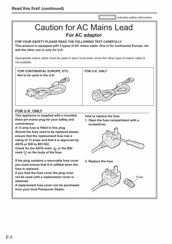
Power sourcesUsing the battery
Installation
Insert the battery until it clicks into place.
Removal
1 Set the POWER/MODE switch to OFF, and check that the mode lamp is off.(Page E-24)
2 While pressing the battery release button, raise up the battery to remove it.•Supportthebatterywithyourhandtoensurethatitwillnotfall.
Mode lamps
Battery release button
Using the AC adaptor
Installation
1 Insert the DC cable’s battery connector until it clicks into place.
2 Connect the AC power supply cable.ConnecttheACpowersupplycableintheorder1and2.
1
2
DC cable’s battery connector
Insert it all the way in.
Removal
1 Set the POWER/MODE switch to OFF, and check that the mode lamp is off.(Page E-24)
2 Remove the DC cable’s battery connector while pressing the battery release button.
3 Disconnect the AC power supply cord from the power outlet.
•DisconnecttheACpowersupplycablefromthepoweroutletwhentheunitisnotgoingtobeused.
•WhentheACpowersupplycableisdisconnectedfromthepoweroutlet,thepowerlampontheACadaptorremainslitforawhilethenshutsoff.Thisisnotamalfunction.

E-21
Adjusting the hand strapAdjustthehandstraptosuityourhand.
1 Open the cover and adjust the length.
2 Close the cover.•Makesurethecoverisfullyclosed.
Attaching the shoulder strapAttachtheshoulderstrapanduseitasaprecautionagainstdroppingthecamera-recorder.
20 mm or more
20 mm or more
Detaching and attaching the lens hoodDetaching the lens hood•Turnthelenshoodcounterclockwisetodetachit.
Attaching the lens hood•Withthefaceonthelenshooddisplayingtheguidepointingupward,aligntheguidewiththecenterofthecameraandattachthelenshood.
•Turnthelenshoodclockwiseuntilitclickstosecureitinposition.
(1)
(2)
Center of camera
Lens hood Face displaying guide
E-22
Prep
arat
ion
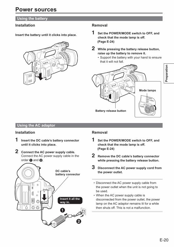
Detaching and attaching the lens capDetaching the lens cap•Pinchthelenscapandremove.
Attaching the lens cap•Pinchthelenscapandattach.•Besuretoattachthelenscaptoprotectthelenswhennotinuse.
Lens cap
Fitting the eye cupAttachtheeyecupbyaligningtheprojectionsontheeyecupholderandeyecupandfittingthemtogether.•Turningtheeyecupafterattachingitmaycausetheeyecupholdertocomeoff.Iftheeyecupholderdoescomeoff,see(Page156ofVol.2)fordetailsonhowtorefitit.
Eye cup holderEye cup
Projection

E-23
The remote controlInsert the battery
1 Push the catch in the direction shown by arrow 1 to remove the holder.
2 Insert the battery with the “+” marked side facing up.
3 Return the holder to its original position.
•Whenthebattery(CR2025)hasrunout,replaceitwithanewone.(Thebatterylastsaboutoneyear,dependingonthefrequencyofuse.)Iftheremotecontrolunitfailstoworkevenwhenitisoperatednearthecamera-recorder’sremotecontrolsensor,thebatteryhasrunout.
• Keep the battery out of the reach of children.
Remote control setupWhenusingtwocamera-recorderssimultaneously,setthiscamera-recorderandtheremotecontroltoeither“operationmode1”or“operationmode2”sotheremotecontroldoesnotoperatethewrongcamera-recorderbymistake.
Setting• Wireless remote controlPresstheoperationbuttonsSTOP()andSTILLADV( )atthesametimetosettheremotecontrolunitforusein“operationmode1”.Alternatively,presstheSTOP()andSTILLADV( )buttonsatthesametimetosettheremotecontrolunitforusein“operationmode2”.Whenthebatteryintheremotecontrolunitisreplaced,theremotecontrolunitissetforusein“operationmode1”.
• Camera-recorderInthesetupmenus,OTHERFUNCTIONSscreen,REMOTE,setto1or2.(Page148ofVol.2)
Ifdifferentsettingsareusedforthecamera-recorderandremotecontrolunit,“REMOTE”lightsinredontheviewfinderandLCDmonitor.
Operation mode 2
Operation mode 1

E-24
Prep
arat
ion
Turn on/off the camera-recorderWhileholdingdownthelockreleasebutton,turnthePOWER/MODEswitchtotheONorOFFposition.Turn on the camera-recorder:Themodelamp(CAMERA)lightsred(CAMERAmode)andthecamera-recorderisnowintheshootingstandbymode.•WhenturningthePOWER/MODEswitchtotheMODEposition,themodelamp(PB/THUMBNAIL)lightsgreenandisPB/THUMBNAILmode.(Page74ofVol.2)
•EachtimeturningthePOWER/MODEswitchtotheMODEposition,themodechangesCAMERAorPB/THUMBNAIL.
Turn off the camera-recorder:Themodelamp(CAMERAorPB/THUMBNAIL)goesout. Lock release button
Mode lamp (CAMERA)
POWER/MODE switch

E-25
Setting the calendarTheCLOCKSETTINGvalueisrecordedinthecontents(clip),andaffectsthesequenceofplaybackofthethumbnails.Beforecarryingoutrecording,besuretocheckandsetCLOCKSETTINGandTIMEZONE.Thisshowsyouhowtoadjustthecalendarto17:20onSeptember25,2011.
1 Set the POWER/MODE switch to ON. (PageE-24)
2 Press the MENU button.
3 Push the Operation lever in the ▲ ▼ direction to set the time difference from Greenwich Mean Time under TIME ZONE on the setting menu OTHER FUNCTIONS screen. (Page149ofVol.2)Factorydefaultsettingis+00:00.
PUSH MENU TO RETURN TIME ZONE
1394 CMD SELACCESS LEDTALLY LAMP
>>>+9:00
STOPONOFF
USER FILEREMOTE1394 CONTROL
>>>1
OFF
CLOCK SETTING
OTHER FUNCTIONS
•Fordetailsonmenuoperation,referto“Usingthesetupmenus”(PageE-27)
•Youcanalsousethecorrespondingbuttonsontheremotecontrol.Fordetails,see“Descriptionofparts”(Remotecontrol).(PageE-18)
4 In the setup menus, OTHER FUNCTIONS screen, CLOCK SETTING, select CHANGE.
PUSH MENU TO RETURN TIME ZONE
1394 CMD SELACCESS LEDTALLY LAMP
STOPONOFF
USER FILEREMOTE1394 CONTROL
>>>1
OFF
CLOCK SETTING
OTHER FUNCTIONS
CHANGERETURN
5 Push the Operation lever in the ◄ ► direction to set YEAR to 2011.
PUSH MENU TO RETURN
MONTHDAYHOURMINUTE
2011YES0112
OCT
00
YEAR
CLOCK SETTING
ChoosethecalendarfromJanuary1st,2000toDecember31,2037.
6 Push the Operation lever in the ▼ direction to move to the MONTH setting.
PUSH MENU TO RETURN
MONTHDAYHOURMINUTE
2011YES0112
OCT
00
YEAR
CLOCK SETTING
7 Push the Operation lever in the ◄ ► direction to set MONTH to SEP.
PUSH MENU TO RETURN
MONTHDAYHOURMINUTE
2011YES0112
SEP
00
YEAR
CLOCK SETTING
8 Set DAY, HOUR, and MINUTE using the method shown in steps 6 and 7.•Thisisa24-hourclock.
PUSH MENU TO RETURN
MONTHDAYHOURMINUTE
2011YES2517
SEP
20
YEAR
CLOCK SETTING
9 Press MENU three times to exit the menus.
•Theclockcanvaryinaccuracysocheckthatthetimeiscorrectbeforeshooting.
•Whenusingthecamera-recorderoverseas,donotsettheCLOCKSETTINGoptiontothelocaltime,butinsteadenterthetimedifferencefromGreenwichmeantimeaccordingtoTIMEZONE.

E-26
Prep
arat
ion
Charging the built-in batteryThecamera-recorder’sinternalbatterysavesthedateandtime.“ ”appearsonthescreenoftheviewfinderorLCDwhentheinternalbatteryisrunninglowoncharge.Dothefollowingtorechargeit.Resetthedateandtimewhenfullyrecharged.
1 Connect the AC adaptor. (PageE-20)•LeavethePOWER/MODEswitchatOFF.
2 Leave the camera-recorder like this for about 4 hours.•Theinternalbatterychargesduringthistime.•RechargethebatteryregularlytoensurecorrectTCandmenuoperations.
If“ ”appearsevenaftercharging,itmeansthattheinternalbatterymustbereplaced.Askyourdealertodothis.

E-27
Using the setup menusUsethesetupmenustochangethesettingstosuitthescenesyouareshootingorwhatyouarerecording.
Operation lever
MENU button
Using the menus
•SettoCAMERAmodeifthecameraisoperatinginanothermode.(Page74ofVol.2)
•Themenuitemsindicatedinthebluecharacterscannotbeused.
1 Press the MENU button when not recording in CAMERA mode.ThefollowingisdisplayedontheviewfinderandLCDscreen.
PUSH MENU TO EXIT
2.SYSTEM SETUP3.SW MODE4.AUTO SW5.RECORDING SETUP6.AUDIO SETUP7.OUTPUT SEL8.DISPLAY SETUP
1.SCENE FILE
MAIN MENU
2 Push the Operation lever in the ▲ or ▼ direction to move the highlight to the setting you want.
3 Press SET on the Operation lever (or push it in the ► direction) to display the items.Example:
PUSH MENU TO RETURN
AGCATWAF
ON6dBONON
A.IRIS
AUTO SW
4 Push the Operation lever in the ▲ or ▼ direction to move to the setting you want.Example:
PUSH MENU TO RETURN
AGCATWAF
ON6dBONON
A.IRIS
AUTO SW
5 Press SET on the Operation lever to confirm the setting.Tochangeavalue,pushtheOperationleverinthe▲or▼directiontochangeasnecessary.Example:
PUSH MENU TO RETURN
AGCATWAF
6dB12dB18dBOFF
A.IRIS
AUTO SW
6 To change other settings, repeat steps 4 and 5.Whenyoufinish,presstheMENUbuttontoreturntothefunctionscreen.
7 To change other functions, repeat steps 2 to 5.Whenyouexitthemenumode,presstheMENUbuttonagaintoreturntothenormalscreen.
Menu
E-28
Men
u
Initializing the menu settingsThemenusettingscontainboththeuserfilesettingsandthescenefilesettings.Youcaninitializethemseparately.
To initialize the user file (i.e. all the settings other than the scene file settings)SelectINITIALinUSERFILEoftheOTHERFUNCTIONSscreen.Thecurrentmenusettingsofuserfilewillreturntothefactorysettings.
To initialize the scene fileFromthe6scenefiles,selecttheoneyouwanttoinitializewiththescenedial.ThenintheSCENEFILEscreen,LOAD/SAVE/INIT,selectINITIAL.Thesettingsforonlytheselectedscenefilearereturnedtothefactorysettings.•Thisdoesnoteffecttheotherscenefiles.
To simultaneously initialize the user file and the scene filesSelectYESunderMENUINITontheOTHERFUNCTIONSscreen.Thisreturnstheuserfileandthe6scenefilestotheirfactorysettings.

E-29
Setup menu structureMAIN MENU
SCENE FILE LOAD/SAVE/INIT(Page129ofVol.2) VFR
FRAME RATESYNC SCAN TYPE
SYSTEM SETUP SYSTEM MODE (SYNCRO SCAN)(Page132ofVol.2) REC FORMAT DETAIL LEVEL
CAMERA MODE V DETAIL LEVELSCAN REVERSE DETAIL CORINGASPECT CONV CHROMA LEVELSETUP CHROMA PHASEPC MODE SELECT COLOR TEMP Ach
COLOR TEMP BchMASTER PEDA. IRIS LEVELDRSDRS EFFECTGAMMAKNEEMATRIXSKIN TONE DTLV DETAIL FREQNAME EDIT
SW MODE LOW GAIN(Page135ofVol.2) MID GAIN
HIGH GAINSUPER GAIN
AUTO SW A.IRIS ATW(Page137ofVol.2) AGC HANDLE ZOOM
ATW W.BAL.PRESETAF USER MAIN
USER1USER2
RECORDING SETUP REC FUNCTION USER3(Page138ofVol.2) ONE SHOT TIME USER4
INTERVAL TIME MF ASSISTSTART DELAY WFMPREREC MODETC MODETCGTC PRESETUB MODEUB PRESETONE CLIP RECSTART TEXT MEMOTIME STAMP
AUDIO SETUP LIMITER CH1(Page140ofVol.2) LIMITER CH2
LIMITER CH3LIMITER CH4
OUTPUT SEL SDI & HDMI SELECT AUTO LEVEL CH3(Page142ofVol.2) SDI & HDMI CHAR AUTO LEVEL CH4
SDI OUT 25M REC CH SELSDI METADATA TEST TONESDI EDH INT MICDOWNCON MODE MIC GAIN1VIDEO OUT CHAR MIC GAIN2VIDEO OUT ZEBRA 1394 AUDIO OUTTC IN/OUT SEL AUDIO OUTTC OUTTC VIDEO SYNC

E-30
Men
u
DISPLAY SETUP EVF PEAK LEVEL(Page144ofVol.2) EVF PEAK FREQ
EVF SETTINGEVF B. LIGHT
CARD FUNCTIONS SCENE FILE EVF COLOR(Page147ofVol.2) USER FILE EVF MODE
SD CARD FORMAT ZEBRA1 DETECTZEBRA2 DETECTZEBRA2
OTHER FUNCTIONS USER FILE MARKER(Page148ofVol.2) REMOTE SAFETY ZONE
1394 CONTROL FOCUS BAR1394 CMD SEL LCD SETTINGACCESS LED SELF SHOOTTALLY LAMP LCD BACKLIGHTCLOCK SETTING DATE/TIMETIME ZONE LEVEL METERGL PHASE ZOOM•FOCUSH PHASE CARD&BATTERYSEEK SELECT P2CARD REMAINMENU INIT OTHER DISPLAY
MENU BACKREC COUNTER
DIAGNOSTIC VERSION(Page150ofVol.2) MODEL NAME
SERIAL NO.OPERATION
OPTION MENU*1 1394 STATUS(Page151ofVol.2) 1394 CONFIG
P.A.P. FILTER
*1:ToopentheOPTIONMENU,holddowntheDISP/MODECHKbuttonandpresstheMENUbutton.

E-31
Reference
Specifications[GENERAL]Supply voltage
DC7.2V(whenthebatteryisused)DC7.9V(whentheACadaptorisused)
Power consumption
15.0W(whentheLCDmonitorisused)
indicatessafetyinformation.
Ambient operating temperature0°Cto40°C
Ambient operating humidity10%to80%(nocondensation)
WeightApprox.2.5kg(excludingbatteryandaccessories)
Dimensions (W x H x D)180mmx195mmx438mm(excludingprotrusions)
[Camera-recorder]Pickup devices1/3-typeprogressive,2.2-megapixel,3MOSsensor
Effective pixels1920(H)×1080(V)
LensOpticalimagestabilizerlens,22xmotorizedzoom,F1.6–3.2(f=3.9mm–86mm)35mmconversion:28mm–616mm(16:9)
Filter diameter72mm
Color separation optical systemPrismsystem
ND filterOFF,1/4,1/16,1/64
Minimum shooting distanceApprox.1m
HoodLarge-sizedlenshoodwithwideangleofview
Gain settings0/+3/+6/+9/+12/+15/+18/+24/+30dB(+24,+30dB:USERSWallocationonly)
Shutter speed settings•60i/60pmode:1/60(OFF),1/100,1/120,1/250,1/500,1/1000,1/2000sec.
•30pmode:1/30(OFF),1/60,1/100,1/120,1/250,1/500,1/1000,1/2000sec.
•24pmode:1/24 (OFF),1/60,1/100,1/120,1/250,1/500,1/1000,1/2000sec.
•50i/50pmode:1/50(OFF),1/60,1/120,1/250,1/500,1/1000,1/2000sec.
• 25pmode:1/25 (OFF),1/50,1/60,1/120,1/250,1/500,1/1000,1/2000sec.
Slow shutter•60i/60pmode:1/15,1/30sec.•30pmode:1/7.5,1/15sec.•24pmode:1/6,1/12sec.•50i/50pmode:1/12.5,1/25sec.•25Pmode:1/6.25,1/12.5sec.
Synchro shutter•60i/60pmode:1/60.0to1/249.8sec.•30pmode:1/30.0to1/249.8sec.•24pmode:1/24.0to1/249.8sec.•50i/50pmode:1/50.0to1/250.0sec.•25pmode:1/25.0to1/250.0sec.

E-32
Ref
eren
ce
Shutter opening angle3degreesto359.5degreesin0.5-degreeincrements
Frame rates•59.94Hzmode:1080p:1/2/4/6/9/12/15/18/20/21/22/24/25/26/27/28/30fps(framespersecond)17step
720p:1/2/4/6/9/12/15/18/20/21/22/24/25/26/27/28/30/32/34/36/40/44/48/54/60fps(framespersecond)25step
•50Hzmode:1080p:1/2/4/6/9/12/15/18/20/21/22/23/24/25fps(framespersecond)14step
720p:1/2/4/6/9/12/15/18/20/21/22/23/24/25/26/27/28/30/32/34/37/42/45/48/50fps(framespersecond)25step
Sensitivity•59.94Hzmode:F7(1080/59.94i,P.A.PFILTER:TYPE2)F10(1080/59.94i,P.A.PFILTER:TYPE1)
•50Hzmode:F8(1080/50i,P.A.PFILTER:TYPE2)F11(1080/50i,P.A.PFILTER:TYPE1)
(2000lx,3200K,89.9%reflectance)Minimum illumination0.2lx(F1.6,Gain+30dB,shutterspeed1/30sec.,P.A.PFILTER:TYPE1)
Digital zoom×2,×5,×10
[Memory card recorder Unit]Recording mediaP2card
Recording FormatsAVC-Intra100/AVC-Intra50/DVCPROHD/DVCPRO50/DVCPRO/DVformatsswitchable
Recording/Playback TimeAVC-Intra100/DVCPROHD: 8 GB×1approx. 8min16 GB×1approx. 16min32 GB×1approx. 32min64 GB×1approx. 64min
AVC-Intra50/DVCPRO50: 8 GB×1approx. 16min16 GB×1approx. 32min32 GB×1approx. 64min64 GB×1approx. 128min
DVCPRO/DV: 8 GB×1approx. 32min16 GB×1approx. 64min32 GB×1approx. 128min64 GB×1approx. 256min
•Thetimeslistedabovecanbecontinuouslyrecordedasoneclip.Thenumberofrecordingclipswillreducetheabovefiguressomewhat.

E-33
[Digital video Unit]Recorded video signals1080/59.94i,1080/29.97p,1080/29.97pN,1080/23.98p,1080/23.98pA,1080/23.98pN,720/59.94p,720/29.97p,720/29.97pN,720/23.98p,720/23.98pN,480/59.94i,480/29.97p,480/23.98p,480/23.98pA,1080/50i,1080/25p,1080/25pN,720/50p,720/25p,720/25pN,576/50i,576/25p
Sampling FrequencyAVC-Intra100/DVCPROHD:Y:74.1758MHz,PB/PR:37.0879MHz(59.94Hz)Y:74.2500MHz,PB/PR:37.1250MHz(50Hz)
DVCPRO50:Y:13.5MHz,PB/PR:6.75MHz
DVCPRO:Y:13.5MHz,PB/PR:3.375MHz
QuantizingAVC-Intra100/AVC-Intra50:10bits
DVCPROHD/DVCPRO50/DVCPRO/DV:8bits
Video Compression FormatAVC-Intra100/AVC-Intra50:MPEG-4AVC/H.264IntraProfile
DVCPROHD:DV-BasedCompression(SMPTE370M)
DVCPRO50/DVCPRO:DV-BasedCompression(SMPTE314M)
DV:DVCompression(IEC61834-2)
[Digital audio Unit]Audio Recording SignalAVC-Intra100/AVC-Intra50/DVCPROHD:48kHz/16bits,4CH
DVCPRO50:48kHz/16bits,4CH
DVCPRO/DV:48kHz/16bits,2CH/4CHswitchable
[Input/Output Unit]GENLOCK INBNC×1,1.0V[p-p],75Ω
VIDEO OUTPinjack×1,1.0V[p-p],75Ω
SDI OUTBNC×1(10bits4:2:2*),0.8V[p-p],75Ω,HD/SDswitchingviamenu*Camerathrough
HDMI OUTHDMITypeA
Built-in MIC INSupportsstereomicrophones
AUDIO IN•XLR×2,3pin(INPUT1,INPUT2)•LINE/MIC/+48Vswitchable•LINE:0dBu•MIC:–40/–50/–60dBuswitchingviamenu
AUDIO OUTPinjack×2(CH1/CH2),Output:316mV,600Ω
Camera remote terminal2.5mmdiameterSuperminijack×1(ZOOM,S/S)
3.5mmdiameterMinijack×1(FOCUS,IRIS)
HeadphoneΦ3.5mmstereominijack×1
Internal speaker20mmdiameter×1
TC IN/OUTBNC×1IN:0.5V[p-p]to8V[p-p],10kΩ
OUT:lowimpedance,2.0±0.5V[p-p]
IEEE13946pins,digitaloutput,compliantwithIEEE1394
Specifications (continued)
E-34
Ref
eren
ce
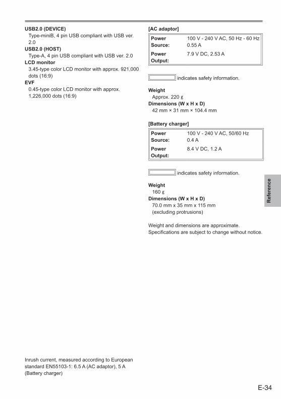
USB2.0 (DEVICE)Type-miniB,4pinUSBcompliantwithUSBver.2.0
USB2.0 (HOST)Type-A,4pinUSBcompliantwithUSBver.2.0
LCD monitor3.45-typecolorLCDmonitorwithapprox.921,000dots(16:9)
EVF0.45-typecolorLCDmonitorwithapprox.1,226,000dots(16:9)
[AC adaptor]
Power Source:
100V-240VAC,50Hz-60Hz0.55A
Power Output:
7.9VDC,2.53A
indicatessafetyinformation.
WeightApprox.220g
Dimensions (W x H x D)42mm×31mm×104.4mm
[Battery charger]
Power Source:
100V-240VAC,50/60Hz0.4A
Power Output:
8.4VDC,1.2A
indicatessafetyinformation.
Weight160g
Dimensions (W x H x D)70.0mmx35mmx115mm(excludingprotrusions)
Weightanddimensionsareapproximate.Specificationsaresubjecttochangewithoutnotice.
Inrushcurrent,measuredaccordingtoEuropeanstandardEN55103-1:6.5A(ACadaptor),5A(Batterycharger)

2011
Information for Users on Collection and Disposal of Old Equipment and used Batteries
Thesesymbolsontheproducts,packaging,and/oraccompanyingdocumentsmeanthatusedelectricalandelectronicproductsandbatteriesshouldnotbemixedwithgeneralhouseholdwaste.Forpropertreatment,recoveryandrecyclingofoldproductsandusedbatteries,pleasetakethemtoapplicablecollectionpoints,inaccordancewithyournationallegislationandtheDirectives2002/96/ECand2006/66/EC.
Bydisposingoftheseproductsandbatteriescorrectly,youwillhelptosavevaluableresourcesandpreventanypotentialnegativeeffectsonhumanhealthandtheenvironmentwhichcouldotherwisearisefrominappropriatewastehandling.
Formoreinformationaboutcollectionandrecyclingofoldproductsandbatteries,pleasecontactyourlocalmunicipality,yourwastedisposalserviceorthepointofsalewhereyoupurchasedtheitems.
Penaltiesmaybeapplicableforincorrectdisposalofthiswaste,inaccordancewithnationallegislation.
Cd
For business users in the European UnionIfyouwishtodiscardelectricalandelectronicequipment,pleasecontactyourdealerorsupplierforfurtherinformation.
Information on Disposal in other Countries outside the European UnionThesesymbolsareonlyvalidintheEuropeanUnion.Ifyouwishtodiscardtheseitems,pleasecontactyourlocalauthoritiesordealerandaskforthecorrectmethodofdisposal.
Note for the battery symbol (bottom two symbol examples): Thissymbolmightbeusedincombinationwithachemicalsymbol.InthiscaseitcomplieswiththerequirementsetbytheDirectiveforthechemicalinvolved.