Memo North Para Dam Raise Feasibility Assessment Stage 3
23
AECOM Australia Pty Ltd Level 10, Tower Two 727 Collins Street Melbourne VIC 3008 Australia www.aecom.com +61 3 9653 1234 tel +61 3 9654 7117 fax ABN 20 093 846 925 p:\605x\60521254\6. draft docs\6.1 reports\memo north para dam raise feasibility assessment stage 3 201710417.docx 1.0 Introduction North Para Dam is a flood mitigation dam located on the North Para River, a tributary of the Gawler River, north of the township of Gawler. AECOM (formerly URS) was engaged in 2003 as the designers for the original North Para Dam which was subsequently constructed in 2007. AECOM has now been engaged by Gawler River Floodplain Management Authority (GRFMA) to provide a fatal flaw screening assessment for the potential raising of North Para Dam by up to 10m to provide additional flood protection for a 1 in 100 year Annual Event Probability (AEP) event to the township of Gawler and further downstream. The scope of the project was split into 3 Stages. Stage 1 of the feasibility assessment included: A brief background review of North Para Dam and the events which have led to conducting a fatal flaw screening assessment for a 10m raise. A fatal flaw screening assessment of the key design aspects to raise the dam which include: o Design criteria and consequence assessment; o Hydrology; o Geology; o Technical design details; and o Construction considerations in particular dam safety during construction. This memorandum includes the outcomes of both Stage 1 and Stage 3 of the feasibility assessment. Stage 1 concluded a 10m raise at North Para Dam was feasible however there were some major challenges that could potentially be fatal flaws for the project which are detailed in Section 3.7. A memorandum was produced at the end of Stage 1, GRFMA reviewed this memorandum and provided approval for AECOM to proceed with Stage 3, noting that the Stage 2 assessment was not required. Stage 3 of the project comprised the development of general arrangement drawings with a high level construction quantity and budget planning cost estimate. Details on the general arrangement and cost estimate are detailed in Section 4 of this memorandum. 2.0 Background The North Para Dam is a flood control dam and was built in 2007 with the design objective of providing flood protection to the township of Gawler for a 1 in 100 AEP event. The dam comprises the main dam and a secondary spillway at the left abutment area. Plate 1 shows an aerial photograph of the dam from the downstream right abutment. The main dam is a roller compacted concrete (RCC) gravity dam with a crest length of approximately 226m of which 150m is the primary spillway. The main dam has a 5m wide crest with a vertical upstream face and stepped downstream face having an overall slope of 0.8H to 1V with 0.9m high steps. The main dam incorporates a low level outlet pipe that is 2.1 m in diameter and twin high level outlets each 1.8m in diameter. The dam will see substantial flows over the spillway in design flood Memorandum To David Hitchcock Page 1 CC Subject North Para Dam Raise Feasibility Assessment Stage 3 From AECOM File/Ref No. Date 13-April- 2017
Transcript of Memo North Para Dam Raise Feasibility Assessment Stage 3

AECOM Australia Pty Ltd
Level 10, Tower Two
727 Collins Street
Melbourne VIC 3008
Australia
www.aecom.com
+61 3 9653 1234 tel
+61 3 9654 7117 fax
ABN 20 093 846 925
p:\605x\60521254\6. draft docs\6.1 reports\memo north para dam raise feasibility assessment stage 3 201710417.docx
1.0 Introduction
North Para Dam is a flood mitigation dam located on the North Para River, a tributary of the Gawler River, north of the township of Gawler. AECOM (formerly URS) was engaged in 2003 as the designers for the original North Para Dam which was subsequently constructed in 2007. AECOM has now been engaged by Gawler River Floodplain Management Authority (GRFMA) to provide a fatal flaw screening assessment for the potential raising of North Para Dam by up to 10m to provide additional flood protection for a 1 in 100 year Annual Event Probability (AEP) event to the township of Gawler and further downstream.
The scope of the project was split into 3 Stages. Stage 1 of the feasibility assessment included:
A brief background review of North Para Dam and the events which have led to conducting a fatal flaw screening assessment for a 10m raise.
A fatal flaw screening assessment of the key design aspects to raise the dam which include:
o Design criteria and consequence assessment;
o Hydrology;
o Geology;
o Technical design details; and
o Construction considerations in particular dam safety during construction.
This memorandum includes the outcomes of both Stage 1 and Stage 3 of the feasibility assessment. Stage 1 concluded a 10m raise at North Para Dam was feasible however there were some major challenges that could potentially be fatal flaws for the project which are detailed in Section 3.7. A memorandum was produced at the end of Stage 1, GRFMA reviewed this memorandum and provided approval for AECOM to proceed with Stage 3, noting that the Stage 2 assessment was not required. Stage 3 of the project comprised the development of general arrangement drawings with a high level construction quantity and budget planning cost estimate. Details on the general arrangement and cost estimate are detailed in Section 4 of this memorandum.
2.0 Background
The North Para Dam is a flood control dam and was built in 2007 with the design objective of providing flood protection to the township of Gawler for a 1 in 100 AEP event. The dam comprises the main dam and a secondary spillway at the left abutment area. Plate 1 shows an aerial photograph of the dam from the downstream right abutment.
The main dam is a roller compacted concrete (RCC) gravity dam with a crest length of approximately 226m of which 150m is the primary spillway. The main dam has a 5m wide crest with a vertical upstream face and stepped downstream face having an overall slope of 0.8H to 1V with 0.9m high steps. The main dam incorporates a low level outlet pipe that is 2.1 m in diameter and twin high level outlets each 1.8m in diameter. The dam will see substantial flows over the spillway in design flood
Memorandum
To David Hitchcock Page 1
CC
Subject North Para Dam Raise Feasibility Assessment Stage 3
From AECOM
File/Ref No. Date 13-April-2017

p:\605x\60521254\6. draft docs\6.1 reports\memo north para dam raise feasibility assessment stage 3 201710417.docx
2 of 23
events, which resulted in the adoption of concrete spillway collection channels on each abutment to direct primary spillway flows to a concrete stilling basin in the base of the river channel.
The secondary spillway structure is an extension of the left abutment of the main dam, as shown in Plate 1. The secondary spillway is also constructed of RCC and has similar features to the main dam section with a 5m crest, vertical upstream face and stepped downstream face with an overall slope of 0.8H to 1V with 0.9m high steps. The secondary spillway height varies in height along its length from 4m to 5m with a maximum height of 7m above the foundation.
Plate 1 Aerial view of North Para Dam
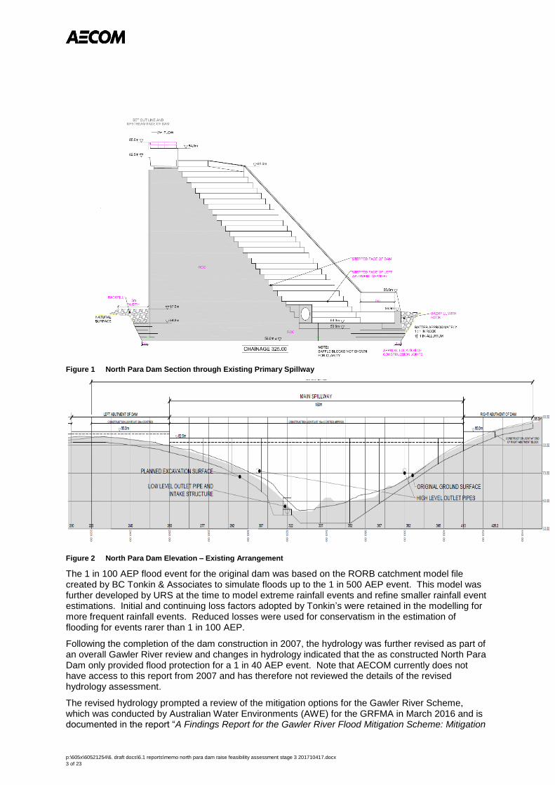
Figure 1 and Figure 2 show a cross section through the existing dam and an upstream elevation respectively of the dam in its current configuration.
Left abutment - secondary spillway
Main Dam
p:\605x\60521254\6. draft docs\6.1 reports\memo north para dam raise feasibility assessment stage 3 201710417.docx
3 of 23
Figure 1 North Para Dam Section through Existing Primary Spillway
Figure 2 North Para Dam Elevation – Existing Arrangement
The 1 in 100 AEP flood event for the original dam was based on the RORB catchment model file created by BC Tonkin & Associates to simulate floods up to the 1 in 500 AEP event. This model was further developed by URS at the time to model extreme rainfall events and refine smaller rainfall event estimations. Initial and continuing loss factors adopted by Tonkin’s were retained in the modelling for more frequent rainfall events. Reduced losses were used for conservatism in the estimation of flooding for events rarer than 1 in 100 AEP.
Following the completion of the dam construction in 2007, the hydrology was further revised as part of an overall Gawler River review and changes in hydrology indicated that the as constructed North Para Dam only provided flood protection for a 1 in 40 AEP event. Note that AECOM currently does not have access to this report from 2007 and has therefore not reviewed the details of the revised hydrology assessment.
The revised hydrology prompted a review of the mitigation options for the Gawler River Scheme, which was conducted by Australian Water Environments (AWE) for the GRFMA in March 2016 and is documented in the report “A Findings Report for the Gawler River Flood Mitigation Scheme: Mitigation

p:\605x\60521254\6. draft docs\6.1 reports\memo north para dam raise feasibility assessment stage 3 201710417.docx
4 of 23
Options Findings”. The report includes a revised hydrology assessment and states there have been some significant changes to the catchments since the 2007 hydrology review however the flood frequency analysis for the North Para River resulted in only a minor peak flow reduction for the 1 in 100 AEP. The construction of the existing North Para Dam is reported in AWE (2016) to have significantly reduced major flooding for a 1 in 20 AEP event but major flooding may occur for a 1 in 50 AEP event in the township of Gawler and further downstream. This is shown in Table 1, extracted from AWE (2016), by a large increase in estimated damages from a 1 in 20 AEP ($24m) to a 1 in 50 AEP ($102m).
Table 1 Flood Damages Summary – Extracted from AWE 2016
Flood Frequency (AEP) Estimated Damages
1 in 10 $15m
1 in 20 $24m
1 in 50 $102m
1 in 100 $182
1 in 200 $212
Average Annual Damage $7.4m
Present Value of Damages* $109m
* Calculated over a thirty year time frame using a discount rate of 7% per annum.
AWE (2016) assessed various mitigation options for the 1 in 100 AEP flood event and concluded that raising the existing North Para Dam by approximately 10m to EL 91.8m was the preferred option.
p:\605x\60521254\6. draft docs\6.1 reports\memo north para dam raise feasibility assessment stage 3 201710417.docx
5 of 23
3.0 Stage 1
3.1 Flood Design Criteria and Consequence Category
Original Dam
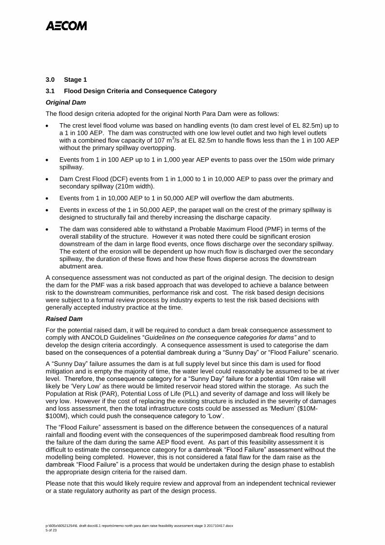
The flood design criteria adopted for the original North Para Dam were as follows:
The crest level flood volume was based on handling events (to dam crest level of EL 82.5m) up to a 1 in 100 AEP. The dam was constructed with one low level outlet and two high level outlets with a combined flow capacity of 107 m
3/s at EL 82.5m to handle flows less than the 1 in 100 AEP
without the primary spillway overtopping.
Events from 1 in 100 AEP up to 1 in 1,000 year AEP events to pass over the 150m wide primary spillway.
Dam Crest Flood (DCF) events from 1 in 1,000 to 1 in 10,000 AEP to pass over the primary and secondary spillway (210m width).
Events from 1 in 10,000 AEP to 1 in 50,000 AEP will overflow the dam abutments.
Events in excess of the 1 in 50,000 AEP, the parapet wall on the crest of the primary spillway is designed to structurally fail and thereby increasing the discharge capacity.
The dam was considered able to withstand a Probable Maximum Flood (PMF) in terms of the overall stability of the structure. However it was noted there could be significant erosion downstream of the dam in large flood events, once flows discharge over the secondary spillway. The extent of the erosion will be dependent up how much flow is discharged over the secondary spillway, the duration of these flows and how these flows disperse across the downstream abutment area.
A consequence assessment was not conducted as part of the original design. The decision to design the dam for the PMF was a risk based approach that was developed to achieve a balance between risk to the downstream communities, performance risk and cost. The risk based design decisions were subject to a formal review process by industry experts to test the risk based decisions with generally accepted industry practice at the time.
Raised Dam
For the potential raised dam, it will be required to conduct a dam break consequence assessment to comply with ANCOLD Guidelines “Guidelines on the consequence categories for dams” and to develop the design criteria accordingly. A consequence assessment is used to categorise the dam based on the consequences of a potential dambreak during a “Sunny Day” or “Flood Failure” scenario.
A “Sunny Day” failure assumes the dam is at full supply level but since this dam is used for flood mitigation and is empty the majority of time, the water level could reasonably be assumed to be at river level. Therefore, the consequence category for a “Sunny Day” failure for a potential 10m raise will likely be ‘Very Low’ as there would be limited reservoir head stored within the storage. As such the Population at Risk (PAR), Potential Loss of Life (PLL) and severity of damage and loss will likely be very low. However if the cost of replacing the existing structure is included in the severity of damages and loss assessment, then the total infrastructure costs could be assessed as ‘Medium’ ($10M-$100M), which could push the consequence category to ‘Low’.
The “Flood Failure” assessment is based on the difference between the consequences of a natural rainfall and flooding event with the consequences of the superimposed dambreak flood resulting from the failure of the dam during the same AEP flood event. As part of this feasibility assessment it is difficult to estimate the consequence category for a dambreak “Flood Failure” assessment without the modelling being completed. However, this is not considered a fatal flaw for the dam raise as the dambreak “Flood Failure” is a process that would be undertaken during the design phase to establish the appropriate design criteria for the raised dam.
Please note that this would likely require review and approval from an independent technical reviewer or a state regulatory authority as part of the design process.
p:\605x\60521254\6. draft docs\6.1 reports\memo north para dam raise feasibility assessment stage 3 201710417.docx
6 of 23
As stated before, the original dam was constructed to structurally withstand the PMF. However as part of the assessment of the Consequence Category of the dam this may indicate that providing full PMF discharge capacity may not be required and a smaller AEP flood event may be considered appropriate as the maximum design flood.
3.2 Hydrology
The report AWE (2016) has assessed approximately what the 100 AEP flood level would be for a raised North Para Dam. However, as stated in Section 3.1, further hydrology modelling will be required to complete a dambreak analysis for the consequence assessment and to establish the design criteria for the elevations of the primary and secondary spillway. This will be an iterative process during the development of the raised dam design. This is not considered a fatal flaw but an engineering design process that will be required to be completed during design.
The hydrology model in AWE (2016) has not been reviewed in detail as part of this project. There were eight revisions of the report which appeared to be reviewed by a steering committee and GRFMA. It is unclear whether GRMFA engaged an independent peer reviewer to review the hydrology model assumptions and inputs. Considering the importance of the hydrology and its implications to the mitigation options to the Gawler River and levels for the potential raised dam, it is recommended the AWE (2016) report is independently peer reviewed, if not already done so.
3.3 Topography and Dam Layout
3.3.1 Dam Layout
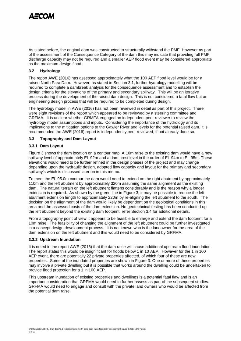
Figure 3 shows the dam location on a contour map. A 10m raise to the existing dam would have a new spillway level of approximately EL 92m and a dam crest level in the order of EL 94m to EL 95m. These elevations would need to be further refined in the design phases of the project and may change depending upon the hydraulic design, adopted flow capacity and layout for the primary and secondary spillway’s which is discussed later on in this memo.
To meet the EL 95.0m contour the dam would need to extend on the right abutment by approximately 110m and the left abutment by approximately 320m assuming the same alignment as the existing dam. The natural terrain on the left abutment flattens considerably and is the reason why a longer extension is required. As shown by the green line in Figure 3, it may be possible to reduce the left abutment extension length to approximately 220m by re-aligning the left abutment to the south. The decision on the alignment of the dam would likely be dependent on the geological conditions in this area and the assessed costs of the dam extension. No geotechnical testing has been conducted up the left abutment beyond the existing dam footprint, refer Section 3.4 for additional details.
From a topography point of view it appears to be feasible to enlarge and extend the dam footprint for a 10m raise. The feasibility of changing the alignment of the left abutment could be further investigated in a concept design development process. It is not known who is the landowner for the area of the dam extension on the left abutment and this would need to be considered by GRFMA.
3.3.2 Upstream Inundation
It is noted in the report AWE (2016) that the dam raise will cause additional upstream flood inundation. The report states this would be insignificant for floods below 1 in 10 AEP. However for the 1 in 100 AEP event, there are potentially 22 private properties affected, of which four of these are new properties. Some of the inundated properties are shown in Figure 3. One or more of these properties may involve a private dwelling but it is possible that works around the dwelling could be undertaken to provide flood protection for a 1 in 100 AEP.
This upstream inundation of existing properties and dwellings is a potential fatal flaw and is an important consideration that GRFMA would need to further assess as part of the subsequent studies. GRFMA would need to engage and consult with the private land owners who would be affected from the potential dam raise.

p:\605x\60521254\6. draft docs\6.1 reports\memo north para dam raise feasibility assessment stage 3 201710417.docx
7 of 23
Figure 3 Contour Plan of North Para Dam

p:\605x\60521254\6. draft docs\6.1 reports\memo north para dam raise feasibility assessment stage 3 201710417.docx
8 of 23
3.4 Geology
The geology at the existing North Para Dam site can be summarised as following:
Within the incised river valley Holocene alluvial soils containing organics and sandy and gravelly layers overlie the bedrock. These were up to 8m deep at the original North Para Dam foundation and were removed to found the dam onto bedrock. These soils were considered unsuitable as founding for the dam or for use as construction materials.
Over the right and left abutments at higher elevations a layer of topsoil existed generally no thicker than 0.5m. This material was removed as it was unsuitable as a foundation or construction material.
On the valley sides and the flatter areas above the dam on both abutments, and below the topsoil, there is a layer of clay and silty sandy clay of medium to high plasticity. There is some variable calcarenite in these soils but generally of minor content. These soils in the secondary spillway area were up to approximately 5m deep overlying weathered bedrock. They were stripped where relatively shallow to expose bedrock as the founding layer for construction. Where they were deeper on the left abutment some of these clays were left in place for the dam foundation and instead a concrete cutoff was constructed to the rock foundation. Based on the As Constructed drawings the cutoff wall in this these areas appears to be in the order of 1.5m to 2m deep and the dam itself is up to approximately 6m high
Underlying the clay on the abutments, or under the Holocene alluvium in the river channel, is micaceous Phyllite the local bedrock of the area. The Phyllite ranges from fresh towards the bottom of the valley to highly weathered on the abutments. In general, the moderately weathered or better Phyllite forms a competent foundation and the majority of the existing dam is founded on this rock. The rock is jointed and foundation profiling is required for dam construction and stability checks for the three predominant joint sets. Plate 2 and Plate 3 show the right and left abutments respectively.
Figure 4 shows the investigations that were undertaken for the original dam, this shows that no investigations beyond the extent of the current dam and secondary spillway were completed at the time of the original North Para Dam design. Based on the conducted geotechnical investigations and knowledge of the local geology the following has been assessed.
Main Dam
The main dam section in the river channel the dam is founded on a competent rock foundation. It is expected that this foundation will be suitable for the raised dam and construction of a new dissipation structure downstream.
Right Abutment
If North Para Dam was to be extended along the dam axis, the right abutment would likely encounter a thin topsoil layer over clay of variable thickness before encountering weathered Phyllite. The clay on the right abutment is not likely to be of excessive thickness and removal to found on MW Phyllite would be required for a concrete dam.
Left Abutment
On the left abutment, portions of the secondary spillway to the east were founded on clay as the Phyllite rock was considered too deep at the time of the original dam construction. It is likely this foundation profile will continue to the east at similar depths. For the extension of the dam the clay will need to be excavated to expose MW Phyllite for a concrete dam foundation. Consideration will need to be given on the requirements for the foundation of the section of the existing secondary spillway that is founded on clay. The raised dam will need to be founded on rock and therefore it is recommended that some of the existing dam section be removed prior to construction of the raised dam.
If the left abutment section of dam remains a secondary spillway for the raised dam then careful consideration is going to need to be given to the dissipation of the spillway flows and the potential for erosion in this area. This may not be a technical fatal flaw for the raised dam but may have large cost implications for the project. It may be preferable to have a non-overflow section for a large portion of

p:\605x\60521254\6. draft docs\6.1 reports\memo north para dam raise feasibility assessment stage 3 201710417.docx
9 of 23
the left abutment to reduce the erosion risks in this area and to have more flow through the primary spillway.
An alternative for the left abutment extension of the dam beyond the secondary spillway could be an embankment constructed over the clay. The decision on a concrete dam versus an embankment dam on the left abutment would be based on technical and cost considerations.
Geology Summary
In summary, it is considered unlikely that there are geological technical fatal flaws within the main dam foundation or the extension of the dam to the east and west. However, the dissipation of spillway flows in the secondary spillway area and the potential for erosion will be a key consideration in the design stages going forward and may have large cost implications on the project.
Further studies would need to be completed early in the next stages of the project and should include site investigations to confirm foundation conditions under the likely dam alignment. These investigations would be firstly to assess the geological conditions across the likely dam alignment and secondly to facilitate a cost evaluation and assessment of concept designs options.

p:\605x\60521254\6. draft docs\6.1 reports\memo north para dam raise feasibility assessment stage 3 201710417.docx
10 of 23
Figure 4 Geotechnical Investigations conducted at North Para Design

p:\605x\60521254\6. draft docs\6.1 reports\memo north para dam raise feasibility assessment stage 3 201710417.docx
11 of 23
3.5 Assessment of Dam Raise Details for a 10m Raise
3.5.1 Main Dam Section
A 10m dam raise for the primary section would likely comprise a downstream raise. The dam shape would be similar to what was used for the original construction of the dam. The upstream dam face could be extended vertically with downstream steps at a grade of 0.8H to 1V, refer Section 4 for additional details and drawings. This would extend the footprint of the main dam by approximately 8m downstream. The raised dam portion could either be constructed of roller compacted concrete or conventional mass concrete and the decision on the type of concrete will likely be driven by a cost and constructability assessment.
Extending the dam footprint downstream will require construction of a new spilling basin further downstream. Raising the dam by 10m will result in additional head and higher flow velocities over the spillway. This will require a larger stilling basin to dissipate the energy of the increase flows. The stilling basin arrangement will be one of the key aspects in the design of the raised spillway. It is unclear whether a larger version of the existing stilling basin layout and details would be suitable for the raised dam or whether a different type of stilling basin is required to dissipate the energy. The size and details of the stilling basin could have large cost implications for the project. Extending the dam and stilling basin downstream will also require further excavation into the alluvial soils down to bedrock which are up to 8m deep.
The drawings in Section 4 show a section through the primary spillway with the estimated new profile after a 10m raise. Overall, the raising of the main dam section is considered technically feasible.

p:\605x\60521254\6. draft docs\6.1 reports\memo north para dam raise feasibility assessment stage 3 201710417.docx
12 of 23
3.5.2 Right Abutment
The right abutment requires an extension of approximately 110m to EL 95.0m. As previously noted, it is expected the upper clay soils are not likely to be of excessive thickness and removal to found on bedrock would be relatively straight forward. The same foundation treatment procedure for the existing right abutment section would be adopted for the raised right abutment, which included cleaning and treatment with dental concrete or grout enriched RCC. Plate 2 shows the right abutment foundation surface during construction of the existing dam. A grout curtain was constructed beneath the primary dam and extended partway up the left and right abutments. It is likely that the grout curtain will need to be extended up the abutments for the raised dam and it will also need to be considered whether the depth of the existing grout curtain is sufficient for the raised head or whether the existing grout curtain needs to be extended deeper into the foundation across the dam.
No fatal flaws have been identified with extending the dam into the right abutment.
Plate 2 Right abutment foundation exposed during construction
3.5.3 Left Abutment
The left abutment will need to be extended between approximately 220m to 320m depending on the final alignment. As stated in Section 3.4, portions of the secondary spillway to the east were founded on clay due to the bedrock being considered too deep at the time of construction. For these sections, a reinforced concrete cutoff to bedrock was constructed underneath the RCC section as shown in Figure 5. This section was constructed between CH 0 and 165m which is the end 165m section of the left abutment. Plate 3 shows the left abutment foundation exposed during construction.

p:\605x\60521254\6. draft docs\6.1 reports\memo north para dam raise feasibility assessment stage 3 201710417.docx
13 of 23
Figure 5 Typical detail of cutoff wall to bedrock on left abutment
Plate 3 Left abutment foundation exposed during construction
A 10m dam raise of the existing secondary spillway using a concrete section would require the clays to be removed to a competent rock foundation as the clays would unlikely have the required bearing capacity to support an additional 10m raise. This would require some 165m of the existing dam sections with a concrete cutoff to be demolished and excavated to rock for the construction of the raised dam arrangement. Alternatively, realigning the dam in this area such that the new dam section is constructed directly downstream of the existing dam on a competent rock foundation could be considered.
As stated in Section 3.4, either a concrete dam section or potentially an embankment over the clay could be considered for the extension of the left abutment beyond the existing secondary spillway. A concrete dam section would need to be taken to a competent rock foundation which could require large excavations and large concrete volumes. An embankment extension would require less

p:\605x\60521254\6. draft docs\6.1 reports\memo north para dam raise feasibility assessment stage 3 201710417.docx
14 of 23
excavation but would present its own challenges with the main issue being designing the connection/tie in of the embankment dam to the RCC section.
The secondary spillway presently has minimal protection for erosion downstream due to the limited head of the flow. The terrain downstream of the secondary spillway has not been shaped to direct flows to the main river channel. This will likely result in erosion in significant AEP events. It was agreed with the client during the detailed design of the original dam that erosion at the larger events was considered acceptable and that remedial works may be required to restore scoured areas created from flows over the secondary spillway. Currently the secondary spillway only operates in AEP events greater than 1 in 1,000 AEP floods and this level of risk was considered acceptable at the time.
If the dam is raised 10m, the potential for scour downstream of the secondary spillway and the left abutment extension and the subsequent dam safety risks would be significantly increased. There are a number of engineering solutions to reduce the downstream scouring which would need to be evaluated during a design development stage. Solutions may include:
Constructing a stilling basin for the full length of the secondary spillway. This would require large widespread excavations to rock and is potentially expensive.
Design the primary spillway to handle larger flood events and thus increasing the AEP event which spills over the secondary spillway or potentially making the existing secondary spillway a non-overflow section.
Designing a more confined lower section in the secondary spillway, similar to the primary spillway, and direct flows to the main channel via shaped terrain or a spillway chute.
Modifying and shaping the area downstream of the secondary spillway to assist in directing flows to the main river channel.
Constructing an embankment section that does not allow overtopping.
Scour issues downstream of the secondary spillway and the left abutment extension from overtopping are a potential fatal flaw for a 10m dam crest raise solution. While defensive design measures could be engineered to reduce the dam safety risks to an acceptable level, it is likely that these measures could come at a substantial cost penalty. The solutions are dependent on the hydrology, hydraulics, geology, constructability and cost. These would be investigated during a design concept development phase if the dam was raised, this is discussed further in Section 3.7.
Overall, the issues identified for the raising of the secondary spillway and extension of the left abutment may not necessarily be considered technical fatal flaws in the raising of the dam, however there could be a large construction cost implications associated with the excavations and concrete construction that could be a fatal flaw for the project from a cost perspective.
3.6 Dam Safety
Dam safety during dam upgrade construction works needs to be considered. It is common practice that upgrade works be staged such that the risks to the safety of the dam are not increased as part of the construction works. Consideration also needs to be given to the risk of flooding of the upstream and downstream inundation areas and that these risks are not increased during upgrade works for events up to the 1 in 100 AEP. Considerations regarding the dam safety and flooding risks during construction include but are not limited to:
Construction of the dissipation structure prior to raising the dam will be required to reduce the scour potential when the dam is raised during construction if a flood event occurs. As the dam is raised, the scour potential is increased from the increased head of water and could present a dam safety risk that would need to be managed.
Construction comprising a downstream raise with RCC or mass concrete that can handle overtopping events during construction
A temporary coffer dam may be required on the left abutment if it is required to remove the sections of the dam which have been constructed on clays with only a cutoff wall to bedrock.
Raising the primary spillway section would likely be a downstream raise and consideration would to be given to diverting the low flow outlets during construction.

p:\605x\60521254\6. draft docs\6.1 reports\memo north para dam raise feasibility assessment stage 3 201710417.docx
15 of 23
3.7 Stage 1 Conclusions
The Stage 1 high level feasibility assessment concluded that although there no obvious identified technical fatal flaws to raising the dam 10m from the information reviewed, there are some major challenges that could be fatal flaws for the project as a whole that include:
Additional properties will be inundated upstream with a 10m raise. GRFMA would need to assess and consider the implications of this as these could potentially be a fatal flaw for the project.
The design and operation of the secondary spillway and the potential for downstream scour is a key risk that will need to be assessed. Options would need to be developed to produce a design with an acceptable level of dam safety risk during rare flood events. This could have large cost implications for the project.
Other key items that need to be considered in the design development include:
A consequence category assessment would be required which requires a dambreak analysis to be completed.
Design criteria would need to be established for a future raise, in particular the flood design criteria for the raised dam.
No geotechnical investigations were conducted outside the current dam’s footprint. Raising the dam by 10m will require an extension of the left abutment by approximately 220m to 320m depending on the final alignment. Geotechnical investigations will need to be conducted in this area.
There are potentially a number of different design options to extend the left abutment. These are dependent on geology, available construction materials, spillway operational requirements, dam safety during construction and cost. These design options would likely be evaluated in a design optimisation process.
Consideration needs to be given to modifying the hydraulic operation of the dam in respect to the amount of flow that passes over the primary and secondary spillways. Due to the costs and risks associated with flows over the secondary spillway it may be concluded that it is more appropriate to have less flow or a non-overflow section in the existing secondary spillway area and that more flow should be passed through the primary spillway instead.
It is likely the upgrade works would need to be staged to address dam safety risks during construction.
4.0 Stage 3 - General Arrangement and Cost Estimate
Stage 3 of the feasibility assessment included the development of General Arrangement Drawings and a Cost Estimate, these are provided in Appendix A and B respectively. The following provides details of the basis for the drawings and estimate.
4.1 General Arrangement – 10m Concrete Dam Raise
The conceptual drawings for the 10m raise are based on the information that has been supplied and reviewed as part of this project. No structural or stability calculations or hydraulic assessments have been conducted as part of this initial feasibility assessment. The key features of the conceptual North Para 10m Dam Raise are as follows;
The 10m dam raise comprises raising the dam with mass concrete to a similar shape to the existing arrangement. The upstream face remains vertical with a 5m wide crest and downstream steps graded at 0.8H to 1V. The main spillway is raised to EL 92.5m (10m above the existing parapet wall level), secondary spillway at EL 94m with the left and right abutments at EL 95m. This provides a freeboard of approximately 3.2m assuming the maximum water level during a 1 in 100 ARI of 91.8m (Australian Water Environment, March 2016).
The design assumes the overflow sections of the main and secondary spillway remain in the same location and for the same length as the existing dam (except raised). Events from 1 in 100 up to 1 in 1,000 AEP to pass over the primary spillway with flows up to 1 in 10,000 AEP to pass

p:\605x\60521254\6. draft docs\6.1 reports\memo north para dam raise feasibility assessment stage 3 201710417.docx
16 of 23
over the primary and secondary spillway. Events greater than the 1 in 10,000 AEP would flow over the entire length of the dam.
No parapet has been included as part of the primary spillway. The previous design included a parapet that was designed to fail at high AEP floods. To assess whether a similar arrangement to this is necessary for the raised dam would require a more detailed assessment of the hydraulic operation of the dam which was not part of the scope of this study. It is recommended further assessment of the hydraulic operation be undertaken to better understand the impact of the 10m raise on the flow rates and spillway configuration for the design floods.
Raising the dam 10m requires extending the left abutment and right abutments to EL 95m. . The left abutment and right abutment have been extended approximately 334m and 120m respectively along the same alignment as the existing dam. The total length of the raised dam is approximately 880m.
We have assumed the entire length of the concrete dam will be founded on moderately weathered or better Phyllite. This requires demolishing the left abutment RCC dam section which is not founded on bedrock (concrete cutoff to bedrock). This was assumed to be between CH 0 and CH 165m. It was assumed the depth to bedrock on the left abutment to be an average of 4m from the existing surface on the left abutment and 2m on the right abutment. It is to be noted that we have no geotechnical investigations in these areas.
The stilling basin would need to be founded on bedrock and the size of the stilling basin would need to be determined based on the energy dissipation requirements assessed during design. Given that hydraulic analysis is out of the scope of this study, it has been assumed that the new stilling basin would be a similar length and design to the existing arrangement and would extend approximately 20m downstream of the toe for 10m dam raise.
The sloped dissipation channel on the left abutment has been extended to CH 0 to account for the additional scour potential of the secondary spillway flows. We have also assumed a downstream excavation to moderately weathered or better Phyllite.
We have assumed steel dowels will be installed at a grid spacing of 0.5m to assist with bonding the new RCC to the existing dam RCC. It would also be required that the existing surface is prepared using hydro-demolition techniques to provide an appropriate surface to place and bond the new concrete.
In the area on the left abutment downstream of the secondary spillway it is likely that excavation works would need to take place to assist in directing the overtopping flows into the river channel. In addition, a stilling basin arrangement (similar to the main spillway) has been included for the entire length of the secondary spillway to dissipate the energy of the overtopping flows.
Beyond the secondary spillway on the left abutment, and beyond the main spillway on the right abutment, it would be required that some erosion protection be included for events greater than the 1 in 10,000 AEP when the abutments overtop. Similar to the design of the existing dam, rockfill has been placed downstream of the dam in these areas, this approach was considered acceptable in the design of the original dam and it was assumed that some repair works would be required following the flood. We have not evaluated the erosion potential and risks associated with erosion as part of this feasibility assessment. This would need to be carefully assessed as part of subsequent design phases to determine whether rockfill is suitable or whether a stilling basin arrangement is required. The inclusion of a stilling basin would add to the overall costs of the project.
4.2 Cost Estimate
A high level cost estimate has been developed for the North Para 10m Dam raise based on the attached drawings DRG 001 to DRG 005. The cost estimate was developed using a top-down unit rate methodology, with quantities for each element of work estimated from the preliminary layout. The rates for the estimate are based on previous project experience for similar type projects and previous cost estimates that were submitted for tender for the construction of North Para Dam in 2006. A Consumer Price Index (CPI) of 3% has been assigned to the existing rates when considering the rates. Given there have been no engineering investigations or design works for the 10m raise
p:\605x\60521254\6. draft docs\6.1 reports\memo north para dam raise feasibility assessment stage 3 201710417.docx
17 of 23
feasibility assessment, this estimate should be considered for preliminary planning purposes only. A copy of the cost estimate is attached to this memorandum.
4.2.1 Direct Costs
The following provides a description of the key construction works items and the cost assumptions.
Preliminaries
We have assumed a value of 15% of the project sum for the project preliminaries. The project preliminaries include the following provisions;
Costs associated with mobilising to site including setting up site facilities, equipment transportation, equipment assembly, staff relocation, etc.
Contractor overheads comprising both the onsite and offsite overheads. The offsite overheads includes costs applied to the project involving business operations, fees, insurances, marketing, proposals, and other costs that do not involve any of the activities performed at the construction site. The onsite overheads include the project staff, site vehicles, ongoing costs for site facilities, etc.
Survey control requirements and contractor documentation including OH&S, environmental, quality systems, etc.
Environmental permits, construction controls, sedimentation ponds, water treatment etc.
Construct and maintain access roads.
Insurances and legal costs.
Communications.
Establish and maintain temporary haul roads, culverts and bridges needed to complete the works.
Cofferdam: Upstream
Construction of a coffer dam upstream of the left abutment. It has been assumed a coffer dam will be required when demolishing the RCC left abutment which is not founded on bedrock to protect the left abutment in a flood event. The coffer dam is assumed to be approximately 160m long with a maximum height of 4m, 3m wide crest and 1V:1H batters. The cofferdam is assumed to be constructed of earthfill with a clay core.
Demolition
It is assumed the RCC dam section on the left abutment which is not founded on bedrock will be demolished. It will also be required to remove the parapet wall, downstream stilling basin and the left and right channel walls.
Excavation to Bedrock
The left and right abutment will be excavated to a moderately weathered or better Phyllite to provide a suitable foundation for the RCC dam. The depth to this rock on the right and left abutment beyond the existing RCC dam footprint is unknown. It has been assumed bedrock is approximately 2m below the existing surface level on the right abutment and an average of 4m on the left abutment.
The downstream stilling basin will be extended downstream which requires excavation to bedrock in the existing river bed.
Foundation Preparation
Foundation preparation includes cleaning the excavated bedrock surface and filling voids with dental concrete.
It has been assumed a grout curtain will be required for the entire length of the right and left concrete dam extensions. The grout curtain depth and spacing for the original dam has been assumed for the left and right RCC abutment extensions.

p:\605x\60521254\6. draft docs\6.1 reports\memo north para dam raise feasibility assessment stage 3 201710417.docx
18 of 23
RCC Surface Preparation
It has been assumed the existing RCC dam surface will require hydro-demolition, cleaning and installation of dowel bars at a grid spacing of 0.5m to provide a bond between the new and old RCC.
Supply and Place RCC
The original dam was constructed using RCC and it has been assumed that RCC would also be used to raise the dam. However it should be noted that access to the raised section of the dam is constrained compared to the original ‘greenfields’ construction and it may be necessary to construct the raise using conventional mass concrete. This would increase the cost of these works.
Mobilisation and demobilisation of a RCC batch plant.
Supply and placement of RCC.
Supply and Place Structural Concrete
Structural concrete will be required for the stilling basin and associated walls and baffle blocks.
Structural concrete will be required for the extension of the left channel wall to CH 0 m.
Outlet Works
The existing outlet works will be extended through the new RCC dam raise section. No design calculations or outlet sizes have been conducted, this has been allocated a lump sum value of $1 million.
Scour Protection
Rockfill is to be placed on the downstream toe of the left and right abutment extensions.
4.2.2 Non-Direct Costs
For each estimate the non-direct costs shown in Table 1 were assumed. These are typical industry values adopted for civil and dam projects of this scale.
Table 2 Non-Direct Cost Items
Non-Direct Cost Percentage of Direct Cost
Contractor Profit 10%
Detailed Design 5%
Design Support during Construction 5%
Owners Representative Services 5%
4.2.3 Other Owner Costs
Project costs to owners include many direct and indirect costs that are not necessarily included in a typical Engineer’s Estimate. It is important that the items be included for planning purposes. The other owner costs that have not been included in the estimate are as follows:
Insurances
Land Acquisition
Costs associated with environmental and regulatory approvals.
4.2.4 Contingency and Level of Accuracy
The United States Society on Dams (USSD) ‘Guidelines for Construction Cost Estimating for Dam Engineers and Owners’ was used to select the level of contingency to be adopted for the estimates and to assess the expected accuracy of the estimate. This document provides details for cost estimating for new dams and dam rehabilitation projects and is written for engineers and dam owners

p:\605x\60521254\6. draft docs\6.1 reports\memo north para dam raise feasibility assessment stage 3 201710417.docx
19 of 23
engaged in the planning, design and construction of dam-related engineering projects anticipated to cost up to $100 million.
Contingency
In the USSD document the level of contingency is assigned based on the ‘Class’ of the estimate. The Class is based on the level of design and the level of detail within the cost estimate. The North Para Dam 10m Raise project could be considered currently as either a Class 5 estimate which is for a project that is between 0% and 2% of project definition or at the low end of a Class 4 estimate which is for a project that is between 1% and 15% of project definition. The level of contingency chosen is based on the major sources of uncertainty which typically include:
Level of geology and geotechnical information;
Design changes, including changes in the level of design definition as project development occurs;
Quantity variations;
Differing site conditions;
Price variations, including escalation, commodity shortages, and labour rate variations; and
Schedule risks, such as the effects of strikes, prolongation of the time between receipt of bids and the issuance of a notice to proceed, excess weather delays, late delivery of major equipment, and others.
The USSD guidance suggests for a Class 5 estimate that an overall contingency of as much as 50% is often appropriate; it also comments that civil works at this level of development should have a minimum contingency of 40%. For Class 4 estimates it suggests a range of between 25% to 40%. North Para Dam 10m Raise is considered to be at either a Class 5 or at the low end of a Class 4 level of design and estimate, therefore a 40% contingency has been adopted.
Level of Accuracy
The USSD document also provides guidance of the expected level of accuracy based on the level of design and the level of detail within the cost estimate, again this is represented in terms of estimate ‘Class’. The details provided by USSD are shown in Table 3. To assign a low and high range to the estimates the mid- value for the Class 5 or high end for the Class 4 estimate was adopted, these are -30% for the low range and +50% for the high range.
Summary
The cost estimate is therefore represented with a 40% contingency as the best estimate and then a low range (-30%) and a high range (+50%) has been applied to the best estimate.

p:\605x\60521254\6. draft docs\6.1 reports\memo north para dam raise feasibility assessment stage 3 201710417.docx
20 of 23
Table 3 USSD Accuracy Matric for Estimating Classes
Primary Characteristic Secondary Characteristic
Estimate Class Level of Project Definition
(expressed as % of complete definition)
End Use (Typical
purpose of estimate)
Methodology
(Typical estimating method)
Expected Accuracy Range
(Typical variation in high and low ranges)
Class 5 0% to 2% Concept screening Capacity Factored Parametric Models, Judgement or Analogy
L: -20% to -50%
H: +30% to +100%
Class 4 1% to 15% Study or Feasibility
Capacity Factored, Parametric Models, Judgement or Analogy
L: -15% to -30%
H: +20% to +50%
Class 3 10% to 40% Budget Authorisation, or Control
Semi-Detailed Unit Costs with Assembly Level Line Items
L: -10% to -20%’
H: +10% to +30%
Class 2 30% to 70% Control or Bid/Tender
Detailed Unit Cost with Forced Detailed Take-off
L: -5% to -15%
H: +5% to +20%
Class 1 50% to 100% Check Estimate or Bid/Tender
Detailed Unit Cost with Detailed Take-Off
L: -3% to -10%
H: +3% to +15%

p:\605x\60521254\6. draft docs\6.1 reports\memo north para dam raise feasibility assessment stage 3 201710417.docx
21 of 23
4.2.5 Cost Estimate Summary
The cost estimate for North Para Dam site is attached to this memorandum. A summary of the cost estimate is presented in Table 4.
Table 4 Summary of North Para 10m Raise Construction Cost Estimate
Item Cost
10m RCC Dam Raise
Direct Costs $34.8m
Project Costs (exc contingency) $44.2m
Best Estimate Total Cost (40% Contingency) $61.9m
Low Estimate (-40%) $37.1m
High Estimate (+50%) $92.9m
Based on the USSD guidelines for a Class 4 estimate class, the best estimate total cost with a 40% contingency is $61.9m with a high and low range between $37.1m and $92.9m.
As shown in Appendix B, the key contributing item to the overall cost estimate is the supply and placement of RCC with an assumed rate of $300/m
3. This equates to approximately 45% of the direct
costs. GFRMA provided AECOM the North Para Dam construction tender submittals which included the major item rates for the construction cost estimates. Bardavcol who were the successful construction contractor had considerably lower supply and placement rates for RCC compared to their competitors. Accounting for a CPI of 3%, Bardavcol rate for supply and place RCC would be $170/m
3.
The other tenders rates for supply and place RCC ranged from $200 to $300. AECOM have adopted a rate of $300/m
3 for this cost estimate as we think this is more appropriate considering previous RCC
rates from similar projects AECOM has been involved with and this project is only at a feasibility stage. A difference of $50/m
3 on the supply and place of RCC has an impact of up to $5m on the Best
Estimate Cost. This highlights the importance of the supply and place RCC rate for this construction cost estimate. As discussed in Section 4.2.1 there is a risk that conventional mass concrete would be required due to construction constraints on placing RCC at the site. Conventional mass concrete would have a unit cost of the order of $400/m
3. As such there is a relatively high level of uncertainty
around the unit rate for concrete to raise the existing dam.
If the raising of North Para Dam is the preferred flood mitigation solution for GRFMA but this cost estimate is above the allocated budget, AECOM would advise to seek additional quotes from local construction contractors. This will provide a more accurate indication of the construction cost estimate.
As stated in Section 3.3.1 of this memorandum, there is the potential to reduce the length of the left abutment by approximately 100m by re-aligning the centreline of the dam to the south. If we assume a linear cost per meter of RCC, it is envisaged this may reduce the construction cost estimate by 10% to 20%. However further investigations of the topography, foundations and hydraulic operation of the dam would be required to assess the feasibility of this layout.

p:\605x\60521254\6. draft docs\6.1 reports\memo north para dam raise feasibility assessment stage 3 201710417.docx
22 of 23
5.0 Conclusions and Recommendations
The major conclusions drawn from the initial feasibility assessment to raise North Para Dam include:
The Stage 1 high level feasibility assessment concluded that although there no obvious identified technical fatal flaws to raising the dam 10m from the information reviewed. However there are some major challenges that could be fatal flaws for the project as a whole that include the following:
Additional properties will be inundated upstream with a 10m raise. GRFMA would need to assess and consider the implications of this as these could potentially be a fatal flaw for the project.
The design and operation of the secondary spillway and the potential for downstream scour is a key risk that will need to be assessed. Options would need to be developed to produce a design with an acceptable level of dam safety risk during rare flood events. This could have large cost implications for the project.
The Best Cost Estimate to raise North Para Dam by 10m is estimated to be $61.9M with a low and high range estimate of $37.1M and $92.9M respectively. The key contributing factor to the cost estimation is the supply and placement rate of RCC which is approximately 45% of the direct costs. There is a risk that conventional mass concrete would be required due to construction constraints on placing RCC at the site. As such there is a relatively high level of uncertainty around the unit rate for concrete to raise the existing dam.
AWE (2016) assessed the downstream flood damages for a 1 in 100 AEP event at $182 million. This suggests that raising the existing dam would have a benefit cost ratio in the order of three and as such further more detailed assessment of the proposed dam raise is recommended.
The following are recommendations for further studies that should be considered by GRFMA:
Considering the importance of the hydrology and its implications to the mitigation options to the Gawler River and levels for the potential raised dam, it is recommended the AWE (2016) report is independently peer reviewed.
In regards to the potential impacts to the upstream inundated existing properties and dwellings it is recommended that GRFMA assess and consider the implications of this before proceeding further with the development of options and concepts for the dam raise. Depending upon the outcomes, GFRMA could also consider a lower raise in future studies to manage these impacts.
A hydraulic assessment of the spillway arrangement has not been completed. The current 10m raise feasibility design assumes the spillway overflow section remains in the same location as the existing dam. The impact and risk of the downstream erosion potential on the left abutment due to the 10m raise has not been evaluated. We recommend assessing the spillway operation of the 10m raise to assess if the hydraulic operation can direct more flow away from the left abutment and through the primary spillway section. Ideally it would be a preference for overtopping to not occur over the full length of the dam and that the left and right abutments have non overflow sections.
A dambreak and consequence category assessment of the dam raise should be conducted as this could impact on the design flood events for the dam raise. This could in turn impact on the overall dam layout and costs.
A more detailed assessment of supply and place RCC rates is considered warranted. The cost estimate shows this is the largest contributing item to the overall construction cost and may be the deciding factor for this flood mitigation option. This assessment could include seeking additional quotes from local construction contractors.
Geotechnical investigations would be required in subsequent studies to assess the foundation conditions along the alignment of the dam extension.
Based on the outcomes of the items above an options study phase that considers a number of hydraulic concepts and dam options along with refined cost estimates would assist in better understanding the overall scope and costs of the dam raise option.

p:\605x\60521254\6. draft docs\6.1 reports\memo north para dam raise feasibility assessment stage 3 201710417.docx
23 of 23
As summarised there are a number of potential additional assessments for GRFMA to consider, AECOM would welcome the opportunity to further discuss and provide a strategy plan to assist GRFMA to progress raising North Para Dam.
6.0 References
ANCOLD, “Guidelines on the Consequence Categories for Dams” October 2012
URS Ltd (2004) “North Para River Flood Control Dam Stage 2 – Geotechnical Report”, prepared for the Gawler River Floodplain Management Authority
URS Ltd (November 2005) “Final Report – North Para River Flood Control Dam Detailed Design Report” prepared for the Gawler River Floodplain Management Authority.
URS Ltd (2008) “North Para River Flood Control Dam Stage 2 – Geotechnical Report”, prepared for the Gawler River Floodplain Management Authority
URS Ltd (2008) “Final Report Engineering Geology of the North Para River – Flood Control Dam”, prepared for the Gawler River Floodplain Management Authority
Argue, Slarke, Rudd, 2008, “Design and construction of a flood mitigation dam on the North Para River, using high paste RCC”, ANCOLD 2008 Conference Technical Proceedings”.
URS (June 2008) “North Para River – Flood Control Dam As-Constructed Drawings”, prepared for the Gawler River Floodplain Management Authority
Australian Water Environments (March 2016) “A Findings Report for the Gawler River Flood Mitigation Scheme – Mitigation Options Findings Final” prepared for Gawler River Floodplain Management Authority
Duncan Banks Steven O’Brien Principal Civil Engineer Associate Director – Dam Engineering [email protected] [email protected]
Mobile: +61.4.9865.3424 Mobile +61.419.519.576 Direct Dial: +61.3.9653.8732 Direct Dial: +61.3.9653.8342