Melting Point Apparatus - Test & Measurement … Point Apparatus ... Melting point determination ......
56
Melting Point Apparatus SMP50 Instructions for use Version1.1
Transcript of Melting Point Apparatus - Test & Measurement … Point Apparatus ... Melting point determination ......
Melting Point Apparatus
SMP50
Instructions for use
Version1.1

2
3
1. Introduction ......................................................................................................................................... 5
2. Safety advice before use..................................................................................................................... 5
3. General description ............................................................................................................................. 5
4. Preparation for use .............................................................................................................................. 6
4.1 Electrical Installation ..................................................................................................................... 6
4.2 Installation ..................................................................................................................................... 6
4.3 Warning ......................................................................................................................................... 7
5. Instrument and software controls ........................................................................................................ 8
5.1 Instrument ..................................................................................................................................... 8
5.2 Connecting the accessory printer ................................................................................................. 8
6. Melting point determination ................................................................................................................ 9
6.1 Terminology .................................................................................................................................. 9
6.2 Temperature Settings ................................................................................................................... 9
6.3 Sample Preparation ...................................................................................................................... 9
7. Operation .......................................................................................................................................... 10
7.1 Power up ..................................................................................................................................... 10
7.2 Main menu screen ...................................................................................................................... 10
7.3 Navigation bar ............................................................................................................................. 11
8. Settings ............................................................................................................................................. 12
8.1 Changing the settings ................................................................................................................. 12
9. Creating a user account .................................................................................................................... 13
10. Setting up a new measurement ...................................................................................................... 15
10.1 More options ............................................................................................................................. 16
10.2 Add measurement protection ................................................................................................... 16
11. Running a melting point determination ........................................................................................... 18
11.1 Sample preparation .................................................................................................................. 18
11.2 Tips on running a melting point determination.......................................................................... 18
11.3 Starting a measurement ........................................................................................................... 18
11.4 Viewing a measurement in progress ........................................................................................ 19
11.5 Aborting a measurement .......................................................................................................... 21
12. Performing a Rapid Melt ................................................................................................................. 22
13. Viewing Melt reports and videos ..................................................................................................... 23
13.1 Manual event tagging ............................................................................................................... 24
13.2 Opening previously saved Melt reports .................................................................................... 26
13.3. Deleting or copying a melt report ............................................................................................. 26
4
14. Managing measurement files .......................................................................................................... 28
14.1 File display ................................................................................................................................ 28
14.2 Searching measurement files ................................................................................................... 29
14.3 Favourites ................................................................................................................................. 31
14.4 Copying and deleting measurement files ................................................................................. 32
14.5 Editing measurements .............................................................................................................. 34
15. Managing results files ..................................................................................................................... 35
15.1 File display ................................................................................................................................ 35
15.2 Searching results files ............................................................................................................... 37
15.3 Favourites ................................................................................................................................. 38
15.4 Copying and deleting results files ............................................................................................. 39
15.5 Viewing results files on a computer .......................................................................................... 42
15.6 Viewing encrypted results files ................................................................................................. 42
16. Printing results ................................................................................................................................ 42
17. Instrument Calibration .................................................................................................................... 44
17.1 Calibration procedure ............................................................................................................... 44
17.2 Calibration correction factor ...................................................................................................... 48
18. Performing a software update ......................................................................................................... 49
19. Maintenance and servicing ............................................................................................................. 50
19.1 Fuse Replacement .................................................................................................................... 50
19.2 Repairs and Support ................................................................................................................. 50
19.3 Cleaning the Sample Block....................................................................................................... 51
20. Warranty .......................................................................................................................................... 52
21. Specification .................................................................................................................................... 52
22. Accessories ..................................................................................................................................... 53
23. Declaration of Conformity................................................................................................................ 54
5
1. Introduction Thank you for purchasing this piece of Stuart equipment. To get the best performance from the SMP50 please read these instructions carefully before use. Before discarding the packaging check that all parts are present and correct.
For your own safety and that of others please read and understand the safety advice given below before using the equipment.
2. Safety advice before use Please read all the information in this manual before using this product.
If the equipment is not used in the manner described in this manual and with accessories other than those recommended by Stuart, the protection provided might be impaired.
Please consult the user manual in all cases where this symbol is identified on the product in order to find out the nature of any potential hazards and any actions that must be taken to avoid them.
This equipment is designed to operate under the following conditions:
• For indoor use only
• Use in a well ventilated area
• Ambient temperature range +5°C to +40°C
• Altitude to 2000m
• Relative humidity not exceeding 80%
• Mains supply fluctuation not exceeding 10%
• Over-voltage category II IEC 60364-4-443
• Pollution degree 2
General safety advice:
• Never move or carry the unit when in use or connected to the mains electricity supply.
• The unit should be carried using both hands with fingers under each side of the frame.
• The ventilation slots at the back or side of the device should not be sealed or obstructed. Leave at least 100mm clearance.
3. General description The SMP50 is designed to automatically measure and record the melting temperatures of crystalline samples held within capillary tubes. Up to three tubes can be accommodated in an illuminated chamber within an aluminium block. The tubes are monitored by a digital camera; the image of which can be viewed on the instrument display during the melting process. The device is designed to be independently operated using the colour touch screen allowing all operational and data management functions to be performed without the need to attach an external computer or keyboard.
The temperature range of the device is ambient to 400°C and the heating rate is variable between 0.1°C and 20°C/minute. All of the instrument functions and menus are accessed using the colour touch screen interface which allows fast and intuitive navigation throughout a melting point determination. The instrument has sufficient internal storage capacity for an almost unlimited number of preset method programs and typically between 250 and 350 result files1. When required, result files can be transferred from the instrument to a USB flash drive for external storage and archiving.
1 The number of result files that can be stored on the SMP50 is largely dependent upon the runtime and size.
6
When a melting point measurement is started the SMP50 heats up to the pre-programmed plateau temperature at the maximum rate before stabilising at the plateau temperature for two minutes. The SMP50 will then start to heat at the pre-programmed rate until the melt is complete or until the device reaches a pre-determined end temperature. Once a melt determination has been completed, cooling is automatically engaged until the instrument reaches 50°C.
The user is able to review the result file and video, reprocessing the automatically determined results if required. The results can also be printed off on the accessory printer.
4. Preparation for use
4.1 Electrical Installation
THIS EQUIPMENT MUST BE EARTHED
Before connecting the instrument, please read and understand these instructions and ensure that the electrical supply corresponds to that shown on the rating plate. This unit is designed for use with a supply rated at 120/230V, 50-60Hz. The power consumption of the unit is 150W. The unit is fitted with an IEC socket at the rear of the instrument for connection of the mains lead.
Caution: Fuses are fitted in both live and neutral lines.
The unit is supplied with three mains leads fitted with IEC plugs: UK, EU and US. Choose the lead appropriate for your electrical installation and discard the other. Should none of the leads be suitable, take the lead with the UK plug and replace the plug with a suitable alternative. This involves cutting off the moulded plug, preparing the cable and connecting to a re-wireable plug in accordance with its instructions.
IT IS IMPORTANT THAT THIS OPERATION SHOULD ONLY BE UNDERTAKEN BY A QUALIFIED ELECTRICIAN.
Refer to the equipment’s rating plate to ensure that the plug and fusing are suitable for the voltage and wattage stated. The wires in the mains cable are coloured as follows:
LIVE BROWN
NEUTRAL BLUE
EARTH GREEN/YELLOW
The appropriate mains lead should be connected to the instrument BEFORE connection to the mains supply. Should the mains lead require replacement, a cable of 1mm2 of harmonised code H05VV-F connected to an IEC320 plug should be used. The UK mains lead is protected by a 10A fuse mounted in the plug top.
• Inadequately rated replacement mains leads, which do not meet the specification above, should not be used.
4.2 Installation
Connect the unit to the electricity supply but DO NOT SWITCH ON. Place the unit on a firm, level, non-slip surface ensuring that there is sufficient free space on all sides without coming into contact with anything else during use. Switch the unit ON at the mains On/Off switch at the rear of the instrument. When switched ON, the touch screen display will illuminate and the interface software will load within 30 seconds.
• Do not position the product so that it is difficult to access the ON/OFF switch.
• Do not position the product so that it is difficult to disconnect from the mains supply.
• Allow the instrument to cool before moving.
IF IN DOUBT CONSULT A QUALIFIED ELECTRICIAN
7
4.3 Warning
High temperatures are dangerous and can cause serious burns to the operator and ignite combustible materials. Great care has been taken in the design of this product to protect operators from hazards, but operators should pay attention to the following points:
• The sample block will become hot during operation and will remain hot for a period after operation.
• Sample capillary tubes will become hot during operation and will remain hot for a period after operation.
• Wait for the sample block and capillary tubes to cool before entering the sample compartment and inserting or removing capillary tubes.
• Use care and wear protective gloves to protect hands when working within the sample compartment and when inserting or removing capillary tubes.
• Do not use combustible substances near hot objects.
• Do not operate the instrument in the vicinity of flammable liquids or gases.
8
5. Instrument and software controls
5.1 Instrument
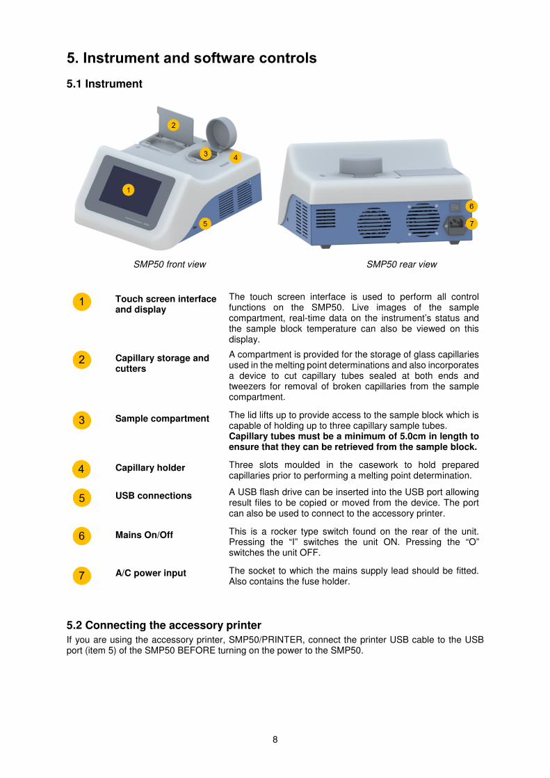
SMP50 front view SMP50 rear view
Touch screen interface and display
The touch screen interface is used to perform all control functions on the SMP50. Live images of the sample compartment, real-time data on the instrument’s status and the sample block temperature can also be viewed on this display.
Capillary storage and cutters
A compartment is provided for the storage of glass capillaries used in the melting point determinations and also incorporates a device to cut capillary tubes sealed at both ends and tweezers for removal of broken capillaries from the sample compartment.
Sample compartment
The lid lifts up to provide access to the sample block which is capable of holding up to three capillary sample tubes. Capillary tubes must be a minimum of 5.0cm in length to ensure that they can be retrieved from the sample block.
Capillary holder
Three slots moulded in the casework to hold prepared capillaries prior to performing a melting point determination.
USB connections
A USB flash drive can be inserted into the USB port allowing result files to be copied or moved from the device. The port can also be used to connect to the accessory printer.
Mains On/Off
This is a rocker type switch found on the rear of the unit. Pressing the “I” switches the unit ON. Pressing the “O” switches the unit OFF.
A/C power input
The socket to which the mains supply lead should be fitted. Also contains the fuse holder.
5.2 Connecting the accessory printer
If you are using the accessory printer, SMP50/PRINTER, connect the printer USB cable to the USB port (item 5) of the SMP50 BEFORE turning on the power to the SMP50.
1
2
3
5
6
7
4
9
6. Melting point determination
6.1 Terminology
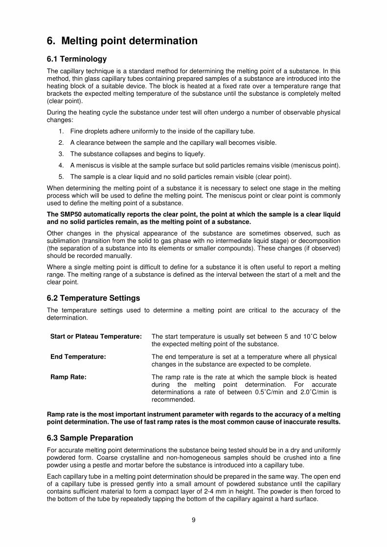
The capillary technique is a standard method for determining the melting point of a substance. In this method, thin glass capillary tubes containing prepared samples of a substance are introduced into the heating block of a suitable device. The block is heated at a fixed rate over a temperature range that brackets the expected melting temperature of the substance until the substance is completely melted (clear point).
During the heating cycle the substance under test will often undergo a number of observable physical changes:
1. Fine droplets adhere uniformly to the inside of the capillary tube.
2. A clearance between the sample and the capillary wall becomes visible.
3. The substance collapses and begins to liquefy.
4. A meniscus is visible at the sample surface but solid particles remains visible (meniscus point).
5. The sample is a clear liquid and no solid particles remain visible (clear point).
When determining the melting point of a substance it is necessary to select one stage in the melting process which will be used to define the melting point. The meniscus point or clear point is commonly used to define the melting point of a substance.
The SMP50 automatically reports the clear point, the point at which the sample is a clear liquid and no solid particles remain, as the melting point of a substance.
Other changes in the physical appearance of the substance are sometimes observed, such as sublimation (transition from the solid to gas phase with no intermediate liquid stage) or decomposition (the separation of a substance into its elements or smaller compounds). These changes (if observed) should be recorded manually.
Where a single melting point is difficult to define for a substance it is often useful to report a melting range. The melting range of a substance is defined as the interval between the start of a melt and the clear point.
6.2 Temperature Settings
The temperature settings used to determine a melting point are critical to the accuracy of the determination.
Start or Plateau Temperature: The start temperature is usually set between 5 and 10˚C below
the expected melting point of the substance.
End Temperature: The end temperature is set at a temperature where all physical changes in the substance are expected to be complete.
Ramp Rate: The ramp rate is the rate at which the sample block is heated during the melting point determination. For accurate determinations a rate of between 0.5˚C/min and 2.0˚C/min is recommended.
Ramp rate is the most important instrument parameter with regards to the accuracy of a melting point determination. The use of fast ramp rates is the most common cause of inaccurate results.
6.3 Sample Preparation
For accurate melting point determinations the substance being tested should be in a dry and uniformly powdered form. Coarse crystalline and non-homogeneous samples should be crushed into a fine powder using a pestle and mortar before the substance is introduced into a capillary tube.
Each capillary tube in a melting point determination should be prepared in the same way. The open end of a capillary tube is pressed gently into a small amount of powdered substance until the capillary contains sufficient material to form a compact layer of 2-4 mm in height. The powder is then forced to the bottom of the tube by repeatedly tapping the bottom of the capillary against a hard surface.
10
Excessive amounts of sample in the capillary tubes will result in inaccurate melting point determinations.
The SMP50 can accommodate up to three sample capillaries. For accurate melting point determinations it is recommended that three samples of the same material are prepared in the same way and analysed at the same time. The average of the three capillaries can then be reported as the melting point.
7. Operation
7.1 Power up
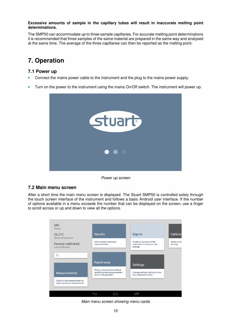
• Connect the mains power cable to the instrument and the plug to the mains power supply.
• Turn on the power to the instrument using the mains On/Off switch. The instrument will power up.
Power up screen
7.2 Main menu screen
After a short time the main menu screen is displayed. The Stuart SMP50 is controlled solely through the touch screen interface of the instrument and follows a basic Android user interface. If the number of options available in a menu exceeds the number that can be displayed on the screen, use a finger to scroll across or up and down to view all the options.
Main menu screen showing menu cards

11
Main menu screen information and cards
Status/Program status: Displays ‘Idle’ unless a measurement is currently running. When a measurement is running it will display the name of the running program, the current block temperature and the camera image of the capillary tubes. The Program status card allows the user access to the program in progress.
Block temperature: Displays the current temperature of the heating block.
Last calibrated: Displays either Factory calibrated or the date of the last user calibration.
Search: Allows the user to search for measurement and result files.
Measurements card: Options to create a new measurement and run, edit, copy or delete existing measurements.
Results card: Options to search, view, copy, print and delete results of previous measurements saved on the instrument.
Rapid ramp card: Run a rapid melting point determination when the specific melting point of a substance is unknown.
Sign in card: Create a user account with your own settings.
Settings card: Define device settings such as time and date, language, temperature units etc.
Calibration card: Perform a user-calibration using the melting points of certified reference standards.
7.3 Navigation bar
Use the keys on the navigation bar to move between screens:
Back Returns to the
previous screen.
Home Returns to the main menu
screen at any time.
Menu Shows open applications.
12
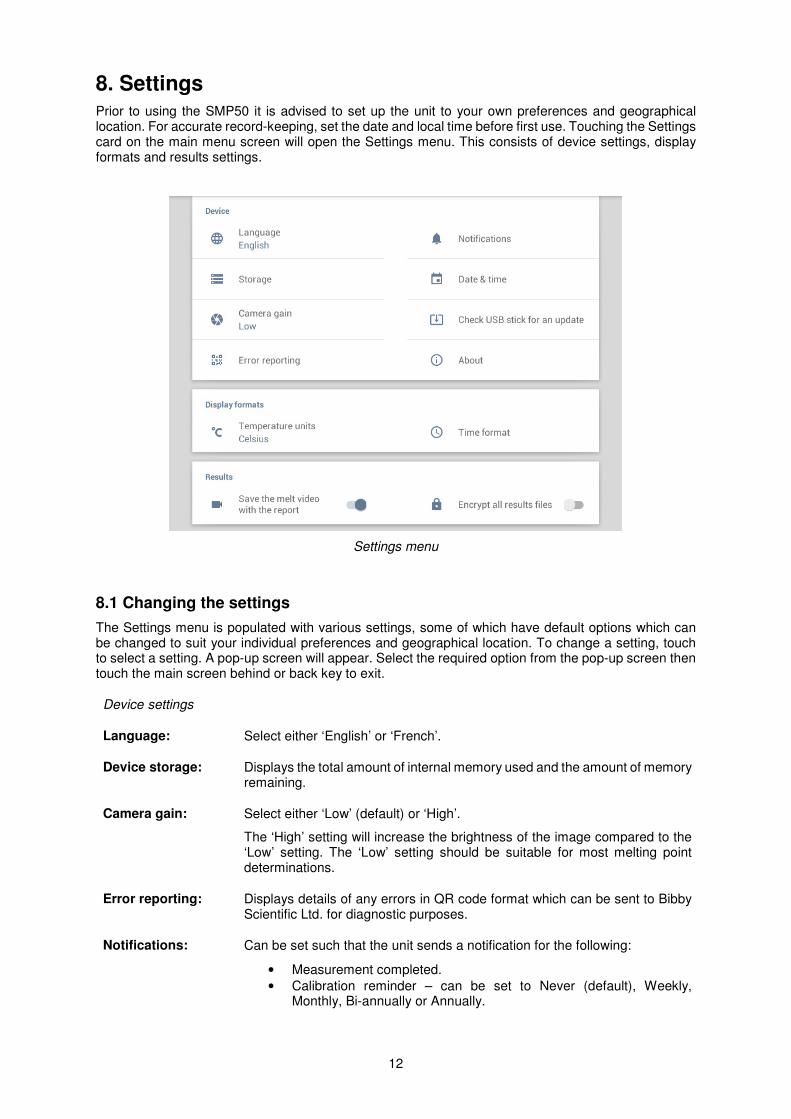
8. Settings Prior to using the SMP50 it is advised to set up the unit to your own preferences and geographical location. For accurate record-keeping, set the date and local time before first use. Touching the Settings card on the main menu screen will open the Settings menu. This consists of device settings, display formats and results settings.
Settings menu
8.1 Changing the settings
The Settings menu is populated with various settings, some of which have default options which can be changed to suit your individual preferences and geographical location. To change a setting, touch to select a setting. A pop-up screen will appear. Select the required option from the pop-up screen then touch the main screen behind or back key to exit.
Device settings
Language: Select either ‘English’ or ‘French’.
Device storage: Displays the total amount of internal memory used and the amount of memory remaining.
Camera gain: Select either ‘Low’ (default) or ‘High’.
The ‘High’ setting will increase the brightness of the image compared to the ‘Low’ setting. The ‘Low’ setting should be suitable for most melting point determinations.
Error reporting: Displays details of any errors in QR code format which can be sent to Bibby Scientific Ltd. for diagnostic purposes.
Notifications: Can be set such that the unit sends a notification for the following:
• Measurement completed.
• Calibration reminder – can be set to Never (default), Weekly, Monthly, Bi-annually or Annually.
13
Date & time: Can be set for regional time zones. Set the date and local time before first use.
Check USB for an update:
Allows you to perform software updates from a USB flash drive. Updates can be downloaded from www.stuart-equipment.com or contact [email protected]. See section 18 for how to perform a software update.
About: Displays information about the currently installed version of software.
Display formats
Temperature units: Select either ‘°Celsius’ or ‘°Fahrenheit’.
Time format: Select either ‘12 Hour’ or ‘24 Hour’.
Results
Save the melt video with the report:
Select ‘ON’ to save the melting video for future reference. Use the slider button to turn on or off.
Encrypt all results files:
Select ‘ON’ to encrypt the results files to prevent post-run editing. Use the slider button to turn on or off.
Note: The SMP50 can serve as part of a US FDA 21 CFR part 11 compliant system relating to its use to generated results in an electronic format. Results generated on the instrument can be copied to a USB flash drive in an encrypted format which is protected against tamper or change. The encrypted file can then be stored in a 21 CFR part 11 compliant system. In order to access the results we provide a reader application which allows a copy of the results to be exported from the encrypted file whilst keeping the original results intact and unchanged. Any system seeking to be compliant with US FDA 21 CFR part 11 must still ensure all other provisions of the regulation are met such as security, auditing, validation and the maintenance of records in an electronic format, along with their submission to the US FDA.
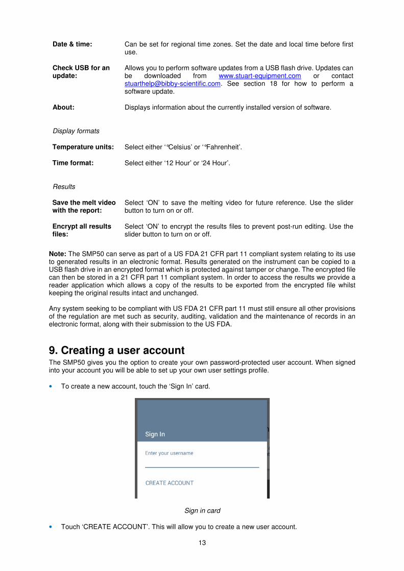
9. Creating a user account The SMP50 gives you the option to create your own password-protected user account. When signed into your account you will be able to set up your own user settings profile.
• To create a new account, touch the ‘Sign In’ card.
Sign in card
• Touch ‘CREATE ACCOUNT’. This will allow you to create a new user account.
14
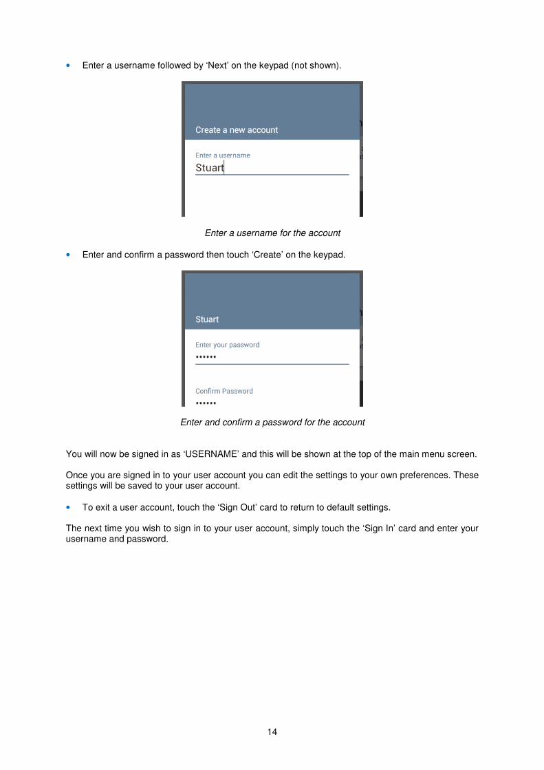
• Enter a username followed by ‘Next’ on the keypad (not shown).
Enter a username for the account
• Enter and confirm a password then touch ‘Create’ on the keypad.
Enter and confirm a password for the account You will now be signed in as ‘USERNAME’ and this will be shown at the top of the main menu screen. Once you are signed in to your user account you can edit the settings to your own preferences. These settings will be saved to your user account.
• To exit a user account, touch the ‘Sign Out’ card to return to default settings. The next time you wish to sign in to your user account, simply touch the ‘Sign In’ card and enter your username and password.
15
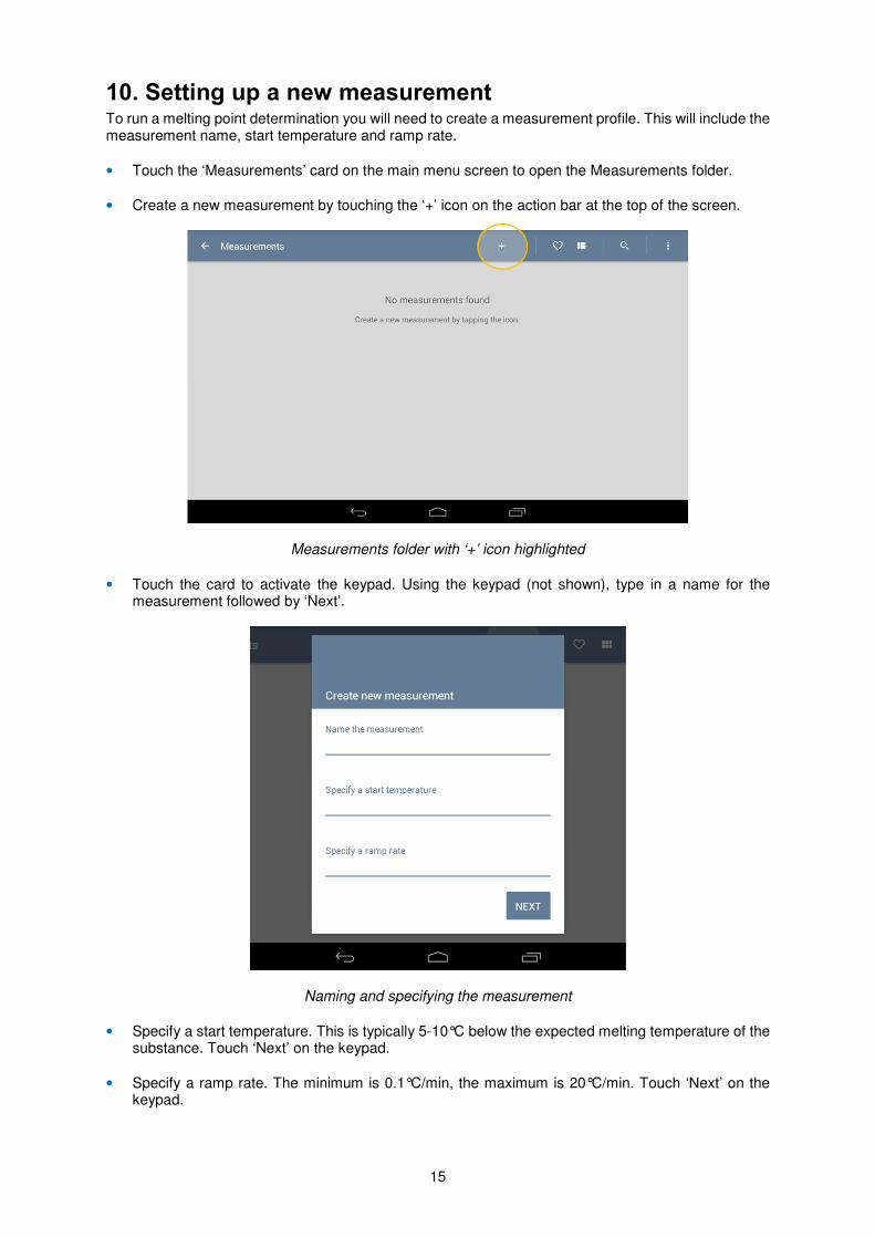
10. Setting up a new measurement To run a melting point determination you will need to create a measurement profile. This will include the measurement name, start temperature and ramp rate.
• Touch the ‘Measurements’ card on the main menu screen to open the Measurements folder.
• Create a new measurement by touching the ‘+’ icon on the action bar at the top of the screen.
Measurements folder with ‘+’ icon highlighted
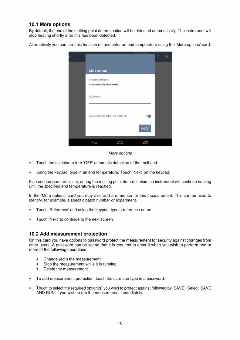
• Touch the card to activate the keypad. Using the keypad (not shown), type in a name for the measurement followed by ‘Next’.
Naming and specifying the measurement
• Specify a start temperature. This is typically 5-10°C below the expected melting temperature of the substance. Touch ‘Next’ on the keypad.
• Specify a ramp rate. The minimum is 0.1°C/min, the maximum is 20°C/min. Touch ‘Next’ on the keypad.
16
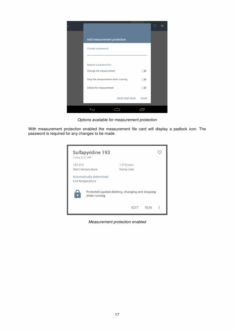
10.1 More options
By default, the end of the melting point determination will be detected automatically. The instrument will stop heating shortly after this has been detected. Alternatively you can turn this function off and enter an end temperature using the ‘More options’ card.
More options
• Touch the selector to turn ‘OFF’ automatic detection of the melt end.
• Using the keypad, type in an end temperature. Touch ‘Next’ on the keypad. If an end temperature is set, during the melting point determination the instrument will continue heating until the specified end temperature is reached. In the ‘More options’ card you may also add a reference for this measurement. This can be used to identify, for example, a specific batch number or experiment.
• Touch ‘Reference’ and using the keypad, type a reference name.
• Touch ‘Next’ to continue to the next screen.
10.2 Add measurement protection
On this card you have options to password protect the measurement for security against changes from other users. A password can be set so that it is required to enter it when you wish to perform one or more of the following operations:
• Change (edit) the measurement.
• Stop the measurement while it is running.
• Delete the measurement.
• To add measurement protection, touch the card and type in a password.
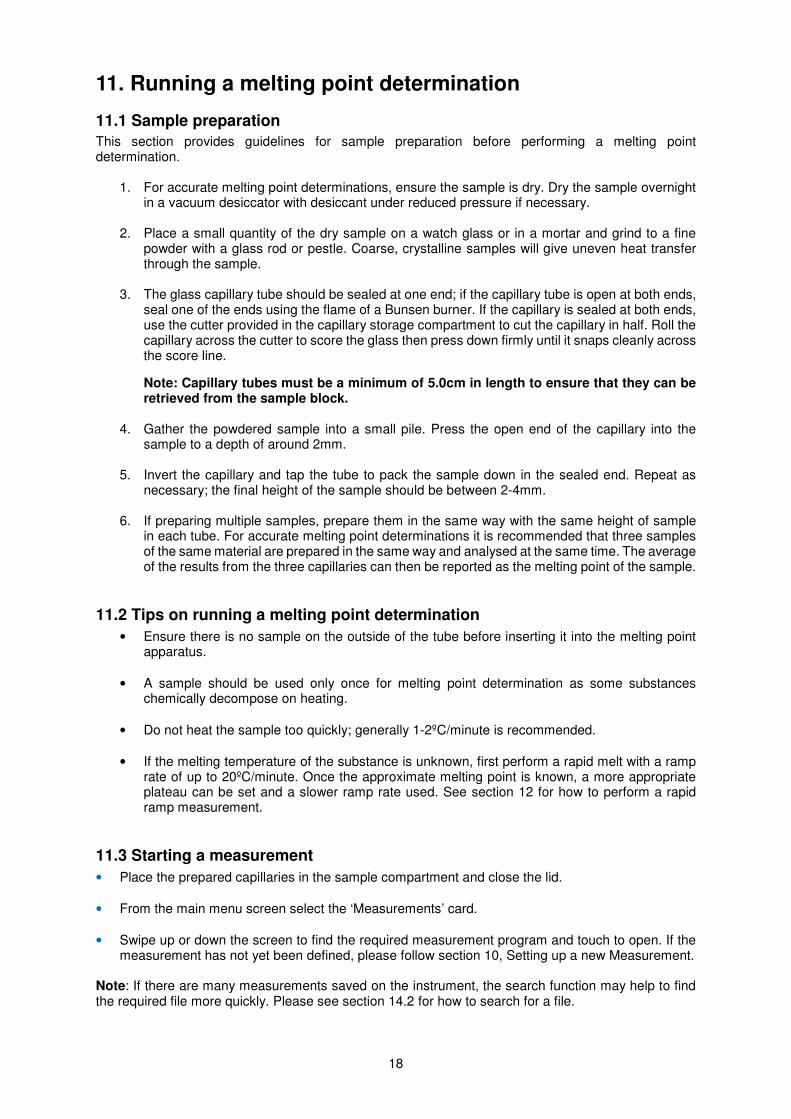
• Touch to select the required option(s) you wish to protect against followed by ‘SAVE’. Select ‘SAVE AND RUN’ if you wish to run the measurement immediately.
17
Options available for measurement protection With measurement protection enabled the measurement file card will display a padlock icon. The password is required for any changes to be made.
Measurement protection enabled
18
11. Running a melting point determination
11.1 Sample preparation
This section provides guidelines for sample preparation before performing a melting point determination.
1. For accurate melting point determinations, ensure the sample is dry. Dry the sample overnight in a vacuum desiccator with desiccant under reduced pressure if necessary.
2. Place a small quantity of the dry sample on a watch glass or in a mortar and grind to a fine powder with a glass rod or pestle. Coarse, crystalline samples will give uneven heat transfer through the sample.
3. The glass capillary tube should be sealed at one end; if the capillary tube is open at both ends,
seal one of the ends using the flame of a Bunsen burner. If the capillary is sealed at both ends, use the cutter provided in the capillary storage compartment to cut the capillary in half. Roll the capillary across the cutter to score the glass then press down firmly until it snaps cleanly across the score line.
Note: Capillary tubes must be a minimum of 5.0cm in length to ensure that they can be retrieved from the sample block.
4. Gather the powdered sample into a small pile. Press the open end of the capillary into the
sample to a depth of around 2mm.
5. Invert the capillary and tap the tube to pack the sample down in the sealed end. Repeat as necessary; the final height of the sample should be between 2-4mm.
6. If preparing multiple samples, prepare them in the same way with the same height of sample
in each tube. For accurate melting point determinations it is recommended that three samples of the same material are prepared in the same way and analysed at the same time. The average of the results from the three capillaries can then be reported as the melting point of the sample.
11.2 Tips on running a melting point determination
• Ensure there is no sample on the outside of the tube before inserting it into the melting point apparatus.
• A sample should be used only once for melting point determination as some substances chemically decompose on heating.
• Do not heat the sample too quickly; generally 1-2ºC/minute is recommended.
• If the melting temperature of the substance is unknown, first perform a rapid melt with a ramp rate of up to 20ºC/minute. Once the approximate melting point is known, a more appropriate plateau can be set and a slower ramp rate used. See section 12 for how to perform a rapid ramp measurement.
11.3 Starting a measurement
• Place the prepared capillaries in the sample compartment and close the lid.
• From the main menu screen select the ‘Measurements’ card.
• Swipe up or down the screen to find the required measurement program and touch to open. If the measurement has not yet been defined, please follow section 10, Setting up a new Measurement.
Note: If there are many measurements saved on the instrument, the search function may help to find the required file more quickly. Please see section 14.2 for how to search for a file.
19
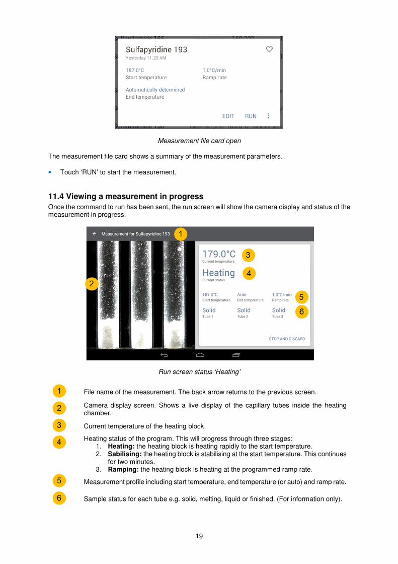
Measurement file card open The measurement file card shows a summary of the measurement parameters.
• Touch ‘RUN’ to start the measurement.
11.4 Viewing a measurement in progress
Once the command to run has been sent, the run screen will show the camera display and status of the measurement in progress.
Run screen status ‘Heating’
File name of the measurement. The back arrow returns to the previous screen.
Camera display screen. Shows a live display of the capillary tubes inside the heating chamber.
Current temperature of the heating block.
Heating status of the program. This will progress through three stages: 1. Heating: the heating block is heating rapidly to the start temperature. 2. Sabilising: the heating block is stabilising at the start temperature. This continues
for two minutes. 3. Ramping: the heating block is heating at the programmed ramp rate.
Measurement profile including start temperature, end temperature (or auto) and ramp rate.
Sample status for each tube e.g. solid, melting, liquid or finished. (For information only).
1
2
3
4
5
6
20
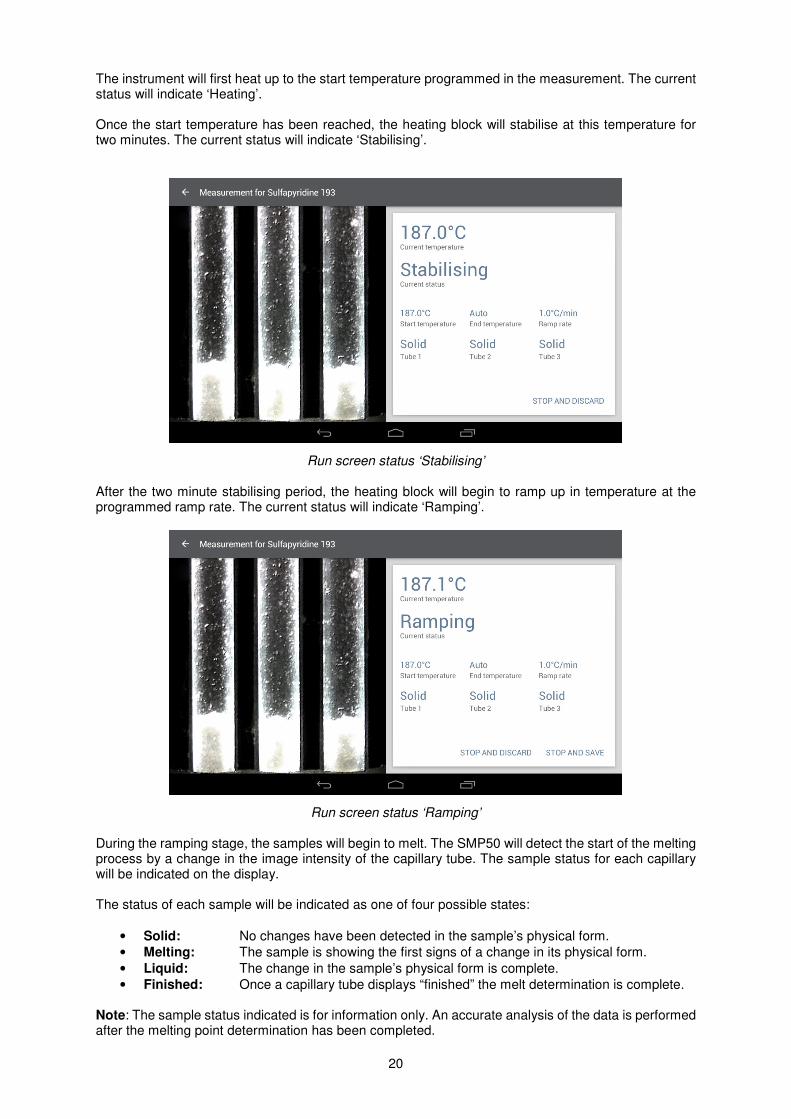
The instrument will first heat up to the start temperature programmed in the measurement. The current status will indicate ‘Heating’. Once the start temperature has been reached, the heating block will stabilise at this temperature for two minutes. The current status will indicate ‘Stabilising’.
Run screen status ‘Stabilising’ After the two minute stabilising period, the heating block will begin to ramp up in temperature at the programmed ramp rate. The current status will indicate ‘Ramping’.
Run screen status ‘Ramping’ During the ramping stage, the samples will begin to melt. The SMP50 will detect the start of the melting process by a change in the image intensity of the capillary tube. The sample status for each capillary will be indicated on the display. The status of each sample will be indicated as one of four possible states:
• Solid: No changes have been detected in the sample’s physical form.
• Melting: The sample is showing the first signs of a change in its physical form.
• Liquid: The change in the sample’s physical form is complete.
• Finished: Once a capillary tube displays “finished” the melt determination is complete. Note: The sample status indicated is for information only. An accurate analysis of the data is performed after the melting point determination has been completed.
21
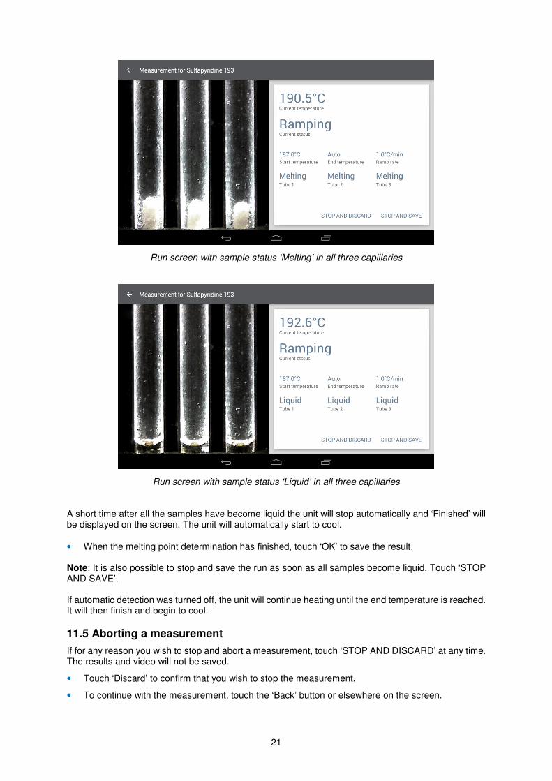
Run screen with sample status ‘Melting’ in all three capillaries
Run screen with sample status ‘Liquid’ in all three capillaries
A short time after all the samples have become liquid the unit will stop automatically and ‘Finished’ will be displayed on the screen. The unit will automatically start to cool.
• When the melting point determination has finished, touch ‘OK’ to save the result. Note: It is also possible to stop and save the run as soon as all samples become liquid. Touch ‘STOP AND SAVE’. If automatic detection was turned off, the unit will continue heating until the end temperature is reached. It will then finish and begin to cool.
11.5 Aborting a measurement
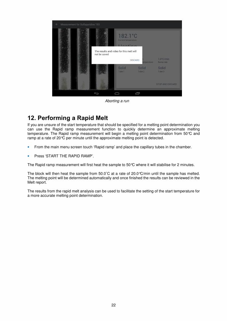
If for any reason you wish to stop and abort a measurement, touch ‘STOP AND DISCARD’ at any time. The results and video will not be saved.
• Touch ‘Discard’ to confirm that you wish to stop the measurement.
• To continue with the measurement, touch the ‘Back’ button or elsewhere on the screen.
22
Aborting a run
12. Performing a Rapid Melt If you are unsure of the start temperature that should be specified for a melting point determination you can use the Rapid ramp measurement function to quickly determine an approximate melting temperature. The Rapid ramp measurement will begin a melting point determination from 50°C and ramp at a rate of 20°C per minute until the approximate melting point is detected.
• From the main menu screen touch ‘Rapid ramp’ and place the capillary tubes in the chamber.
• Press ‘START THE RAPID RAMP’.
The Rapid ramp measurement will first heat the sample to 50°C where it will stabilise for 2 minutes. The block will then heat the sample from 50.0˚C at a rate of 20.0°C/min until the sample has melted. The melting point will be determined automatically and once finished the results can be reviewed in the Melt report. The results from the rapid melt analysis can be used to facilitate the setting of the start temperature for a more accurate melting point determination.
23
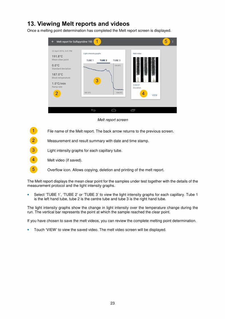
13. Viewing Melt reports and videos Once a melting point determination has completed the Melt report screen is displayed.
Melt report screen
File name of the Melt report. The back arrow returns to the previous screen.
Measurement and result summary with date and time stamp.
Light intensity graphs for each capillary tube.
Melt video (if saved).
Overflow icon. Allows copying, deletion and printing of the melt report.
The Melt report displays the mean clear point for the samples under test together with the details of the measurement protocol and the light intensity graphs.
• Select ‘TUBE 1’, ‘TUBE 2’ or ‘TUBE 3’ to view the light intensity graphs for each capillary. Tube 1 is the left hand tube, tube 2 is the centre tube and tube 3 is the right hand tube.
The light intensity graphs show the change in light intensity over the temperature change during the run. The vertical bar represents the point at which the sample reached the clear point. If you have chosen to save the melt videos, you can review the complete melting point determination.
• Touch ‘VIEW’ to view the saved video. The melt video screen will be displayed.
1
2
3
4
5
24
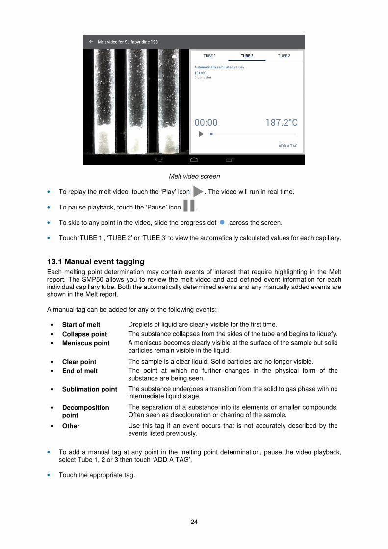
Melt video screen
• To replay the melt video, touch the ‘Play’ icon . The video will run in real time.
• To pause playback, touch the ‘Pause’ icon .
• To skip to any point in the video, slide the progress dot across the screen.
• Touch ‘TUBE 1’, ‘TUBE 2’ or ‘TUBE 3’ to view the automatically calculated values for each capillary.
13.1 Manual event tagging
Each melting point determination may contain events of interest that require highlighting in the Melt report. The SMP50 allows you to review the melt video and add defined event information for each individual capillary tube. Both the automatically determined events and any manually added events are shown in the Melt report. A manual tag can be added for any of the following events:
• Start of melt Droplets of liquid are clearly visible for the first time.
• Collapse point The substance collapses from the sides of the tube and begins to liquefy.
• Meniscus point A meniscus becomes clearly visible at the surface of the sample but solid particles remain visible in the liquid.
• Clear point The sample is a clear liquid. Solid particles are no longer visible.
• End of melt The point at which no further changes in the physical form of the substance are being seen.
• Sublimation point The substance undergoes a transition from the solid to gas phase with no intermediate liquid stage.
• Decomposition point
The separation of a substance into its elements or smaller compounds. Often seen as discolouration or charring of the sample.
• Other Use this tag if an event occurs that is not accurately described by the events listed previously.
• To add a manual tag at any point in the melting point determination, pause the video playback, select Tube 1, 2 or 3 then touch ‘ADD A TAG’.
• Touch the appropriate tag.
25
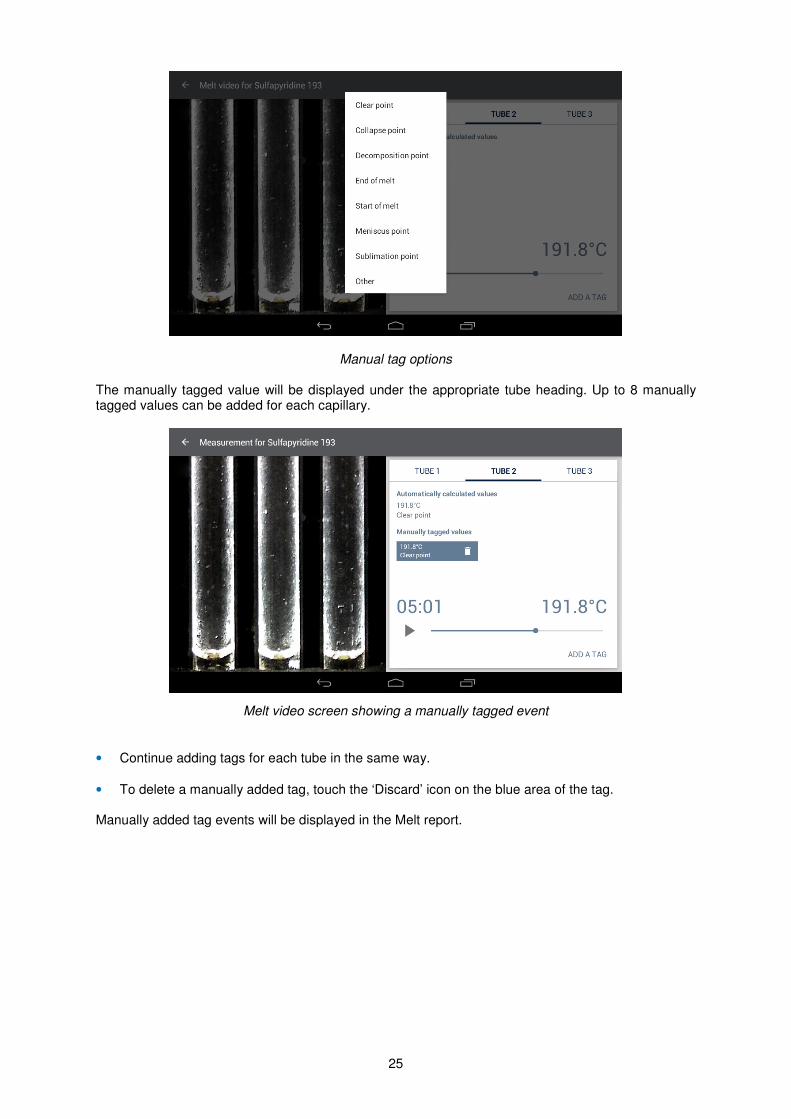
Manual tag options The manually tagged value will be displayed under the appropriate tube heading. Up to 8 manually tagged values can be added for each capillary.
Melt video screen showing a manually tagged event
• Continue adding tags for each tube in the same way.
• To delete a manually added tag, touch the ‘Discard’ icon on the blue area of the tag. Manually added tag events will be displayed in the Melt report.
26
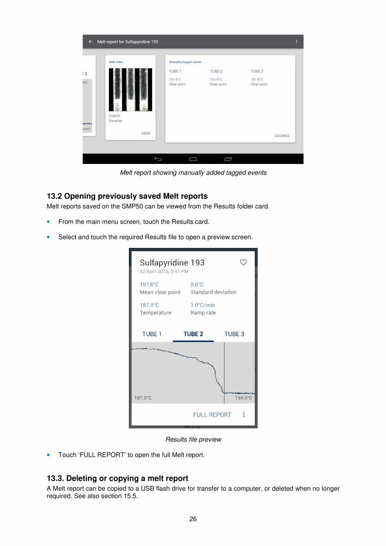
Melt report showing manually added tagged events
13.2 Opening previously saved Melt reports
Melt reports saved on the SMP50 can be viewed from the Results folder card.
• From the main menu screen, touch the Results card.
• Select and touch the required Results file to open a preview screen.
Results file preview
• Touch ‘FULL REPORT’ to open the full Melt report.
13.3. Deleting or copying a melt report
A Melt report can be copied to a USB flash drive for transfer to a computer, or deleted when no longer required. See also section 15.5.
27
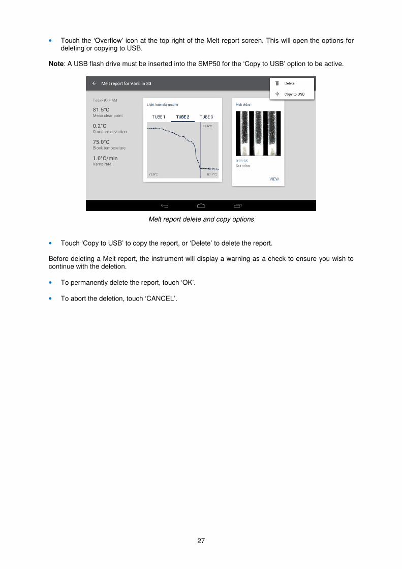
• Touch the ‘Overflow’ icon at the top right of the Melt report screen. This will open the options for deleting or copying to USB.
Note: A USB flash drive must be inserted into the SMP50 for the ‘Copy to USB’ option to be active.
Melt report delete and copy options
• Touch ‘Copy to USB’ to copy the report, or ‘Delete’ to delete the report. Before deleting a Melt report, the instrument will display a warning as a check to ensure you wish to continue with the deletion.
• To permanently delete the report, touch ‘OK’.
• To abort the deletion, touch ‘CANCEL’.
28
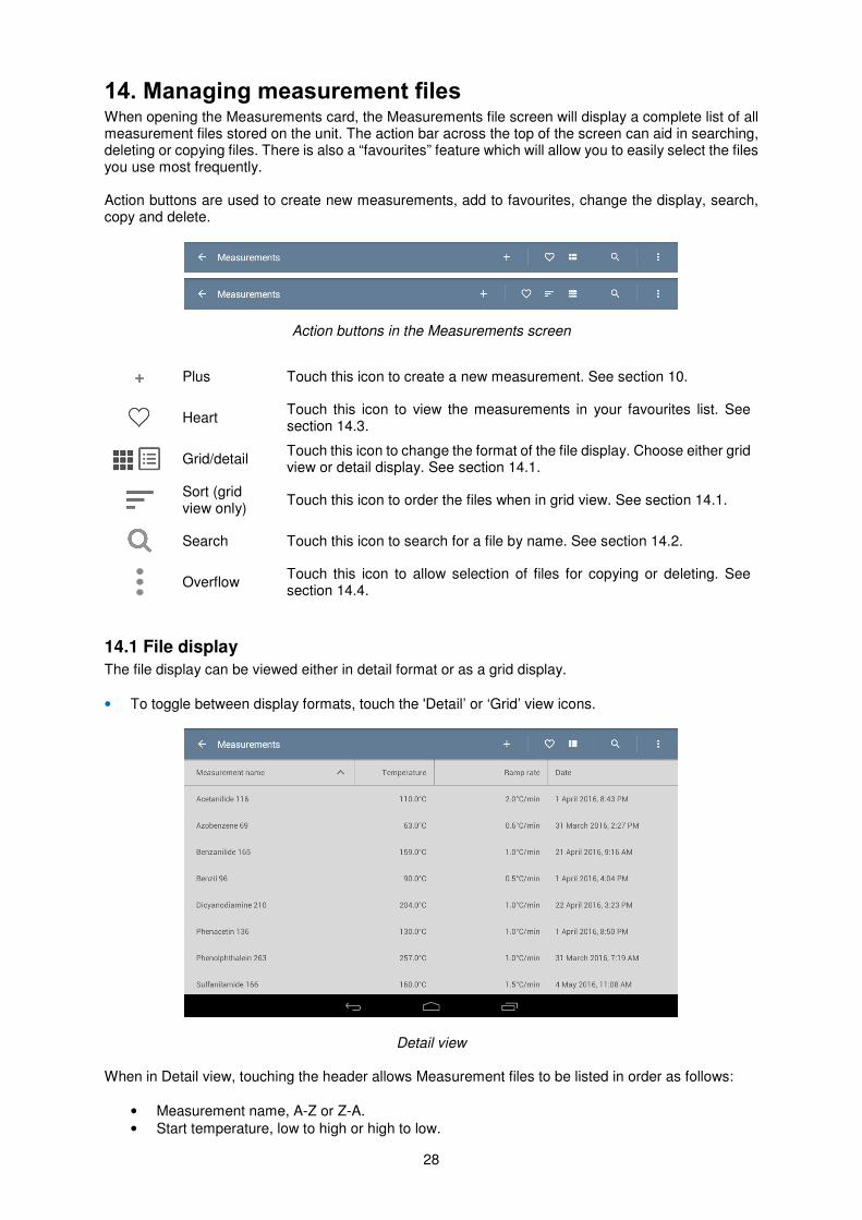
14. Managing measurement files When opening the Measurements card, the Measurements file screen will display a complete list of all measurement files stored on the unit. The action bar across the top of the screen can aid in searching, deleting or copying files. There is also a “favourites” feature which will allow you to easily select the files you use most frequently. Action buttons are used to create new measurements, add to favourites, change the display, search, copy and delete.
Action buttons in the Measurements screen
+ Plus Touch this icon to create a new measurement. See section 10.
Heart Touch this icon to view the measurements in your favourites list. See section 14.3.
Grid/detail
Touch this icon to change the format of the file display. Choose either grid view or detail display. See section 14.1.
Sort (grid view only)
Touch this icon to order the files when in grid view. See section 14.1.
Search Touch this icon to search for a file by name. See section 14.2.
Overflow
Touch this icon to allow selection of files for copying or deleting. See section 14.4.
14.1 File display
The file display can be viewed either in detail format or as a grid display.
• To toggle between display formats, touch the 'Detail’ or ‘Grid’ view icons.
Detail view When in Detail view, touching the header allows Measurement files to be listed in order as follows:
• Measurement name, A-Z or Z-A.
• Start temperature, low to high or high to low.
29
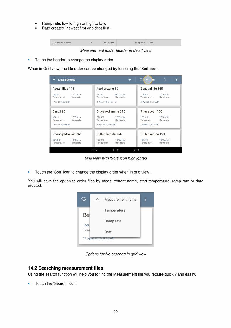
• Ramp rate, low to high or high to low.
• Date created, newest first or oldest first.
Measurement folder header in detail view
• Touch the header to change the display order. When in Grid view, the file order can be changed by touching the ‘Sort’ icon.
Grid view with ‘Sort’ icon highlighted
• Touch the ‘Sort’ icon to change the display order when in grid view. You will have the option to order files by measurement name, start temperature, ramp rate or date created.
Options for file ordering in grid view
14.2 Searching measurement files
Using the search function will help you to find the Measurement file you require quickly and easily.
• Touch the ‘Search’ icon.
30
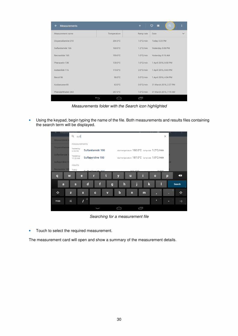
Measurements folder with the Search icon highlighted
• Using the keypad, begin typing the name of the file. Both measurements and results files containing the search term will be displayed.
Searching for a measurement file
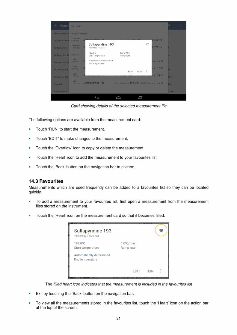
• Touch to select the required measurement. The measurement card will open and show a summary of the measurement details.
31
Card showing details of the selected measurement file The following options are available from the measurement card:
• Touch ‘RUN’ to start the measurement.
• Touch ‘EDIT’ to make changes to the measurement.
• Touch the ‘Overflow’ icon to copy or delete the measurement
• Touch the ‘Heart’ icon to add the measurement to your favourites list.
• Touch the ‘Back’ button on the navigation bar to escape.
14.3 Favourites
Measurements which are used frequently can be added to a favourites list so they can be located quickly.
• To add a measurement to your favourites list, first open a measurement from the measurement files stored on the instrument.
• Touch the ‘Heart’ icon on the measurement card so that it becomes filled.
The filled heart icon indicates that the measurement is included in the favourites list
• Exit by touching the ‘Back’ button on the navigation bar.
• To view all the measurements stored in the favourites list, touch the ‘Heart’ icon on the action bar at the top of the screen.
32
• To remove a measurement from the favourites list, repeat the process, touching the heart icon so that it becomes un-filled.
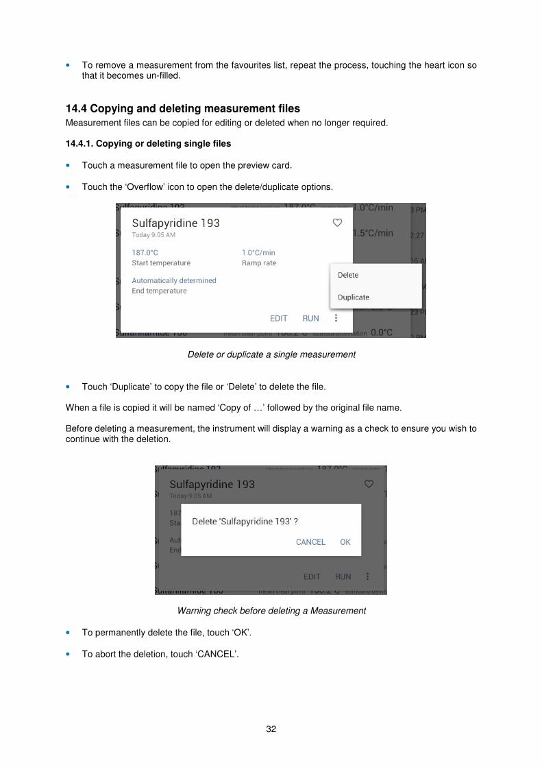
14.4 Copying and deleting measurement files
Measurement files can be copied for editing or deleted when no longer required. 14.4.1. Copying or deleting single files
• Touch a measurement file to open the preview card.
• Touch the ‘Overflow’ icon to open the delete/duplicate options.
Delete or duplicate a single measurement
• Touch ‘Duplicate’ to copy the file or ‘Delete’ to delete the file. When a file is copied it will be named ‘Copy of …’ followed by the original file name. Before deleting a measurement, the instrument will display a warning as a check to ensure you wish to continue with the deletion.
Warning check before deleting a Measurement
• To permanently delete the file, touch ‘OK’.
• To abort the deletion, touch ‘CANCEL’.
33
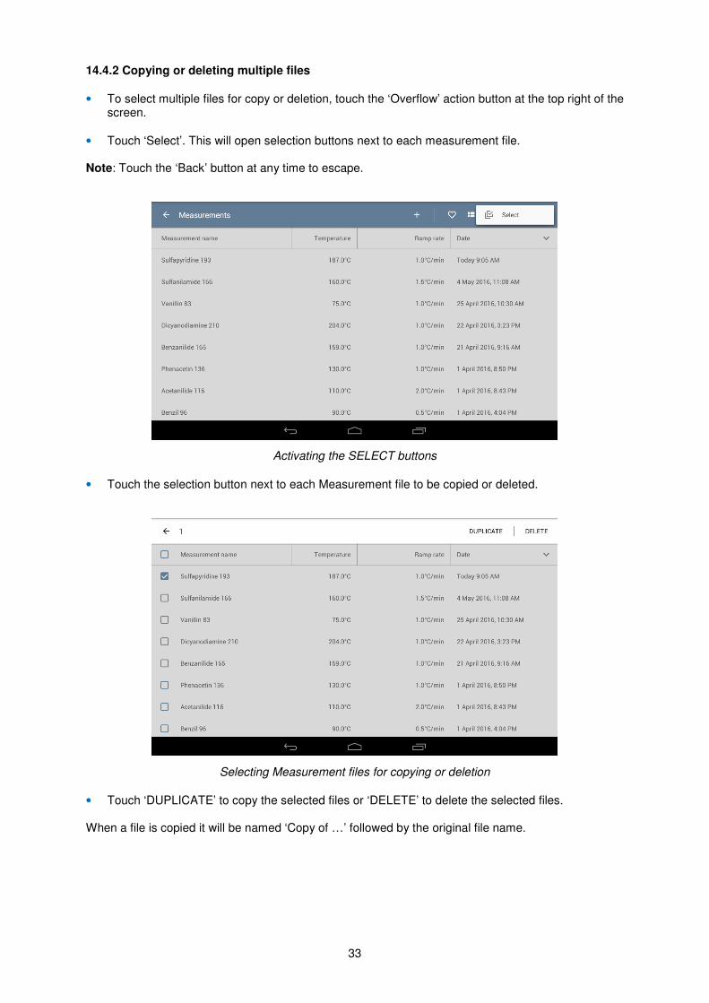
14.4.2 Copying or deleting multiple files
• To select multiple files for copy or deletion, touch the ‘Overflow’ action button at the top right of the screen.
• Touch ‘Select’. This will open selection buttons next to each measurement file. Note: Touch the ‘Back’ button at any time to escape.
Activating the SELECT buttons
• Touch the selection button next to each Measurement file to be copied or deleted.
Selecting Measurement files for copying or deletion
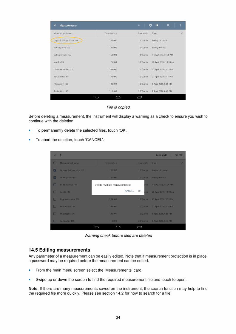
• Touch ‘DUPLICATE’ to copy the selected files or ‘DELETE’ to delete the selected files. When a file is copied it will be named ‘Copy of …’ followed by the original file name.
34
File is copied Before deleting a measurement, the instrument will display a warning as a check to ensure you wish to continue with the deletion.
• To permanently delete the selected files, touch ‘OK’.
• To abort the deletion, touch ‘CANCEL’.
Warning check before files are deleted
14.5 Editing measurements
Any parameter of a measurement can be easily edited. Note that if measurement protection is in place, a password may be required before the measurement can be edited.
• From the main menu screen select the ‘Measurements’ card.
• Swipe up or down the screen to find the required measurement file and touch to open.
Note: If there are many measurements saved on the instrument, the search function may help to find the required file more quickly. Please see section 14.2 for how to search for a file.
35
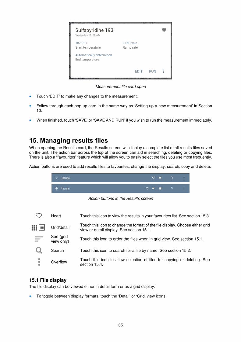
Measurement file card open
• Touch ‘EDIT’ to make any changes to the measurement.
• Follow through each pop-up card in the same way as ‘Setting up a new measurement’ in Section 10.
• When finished, touch ‘SAVE’ or ‘SAVE AND RUN’ if you wish to run the measurement immediately.
15. Managing results files When opening the Results card, the Results screen will display a complete list of all results files saved on the unit. The action bar across the top of the screen can aid in searching, deleting or copying files. There is also a “favourites” feature which will allow you to easily select the files you use most frequently. Action buttons are used to add results files to favourites, change the display, search, copy and delete.
Action buttons in the Results screen
Heart Touch this icon to view the results in your favourites list. See section 15.3.
Grid/detail
Touch this icon to change the format of the file display. Choose either grid view or detail display. See section 15.1.
Sort (grid view only)
Touch this icon to order the files when in grid view. See section 15.1.
Search Touch this icon to search for a file by name. See section 15.2.
Overflow
Touch this icon to allow selection of files for copying or deleting. See section 15.4.
15.1 File display
The file display can be viewed either in detail form or as a grid display.
• To toggle between display formats, touch the 'Detail’ or ‘Grid’ view icons.
36
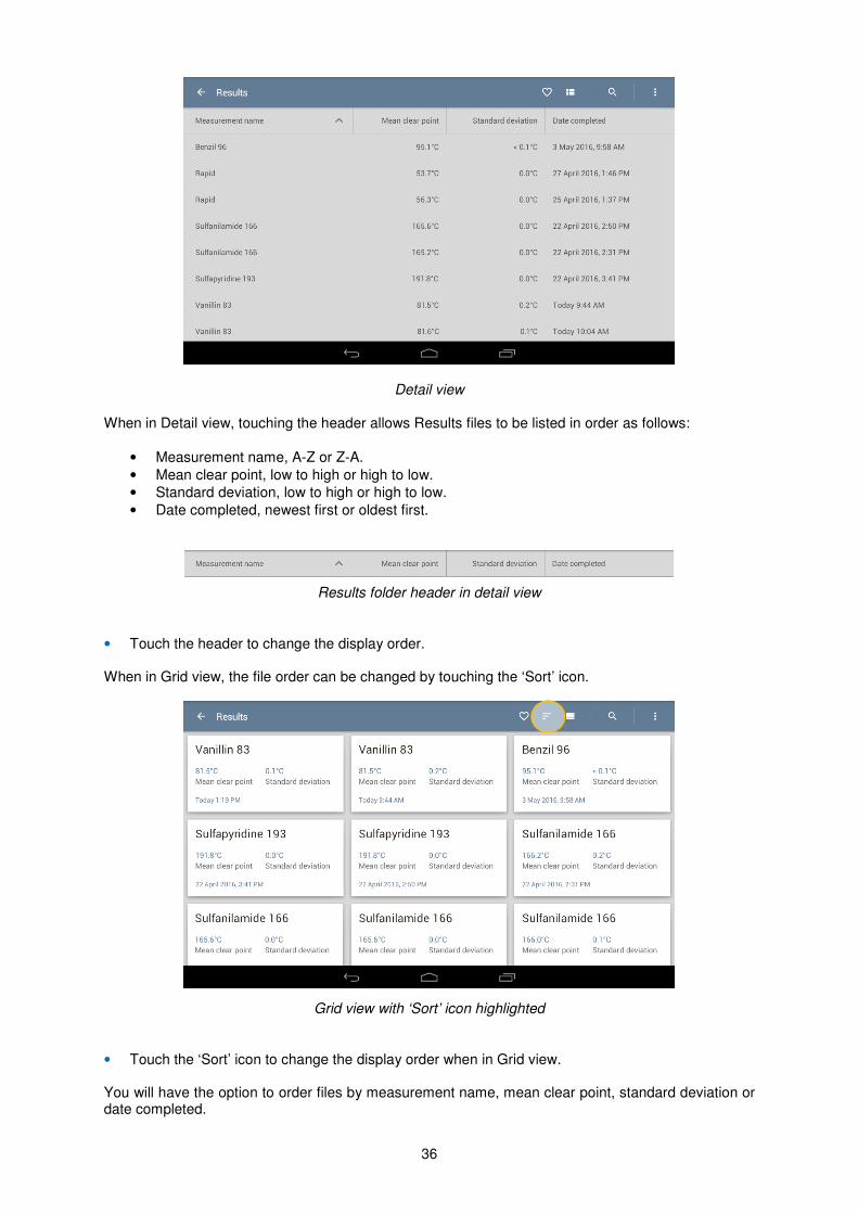
Detail view When in Detail view, touching the header allows Results files to be listed in order as follows:
• Measurement name, A-Z or Z-A.
• Mean clear point, low to high or high to low.
• Standard deviation, low to high or high to low.
• Date completed, newest first or oldest first.
Results folder header in detail view
• Touch the header to change the display order.
When in Grid view, the file order can be changed by touching the ‘Sort’ icon.
Grid view with ‘Sort’ icon highlighted
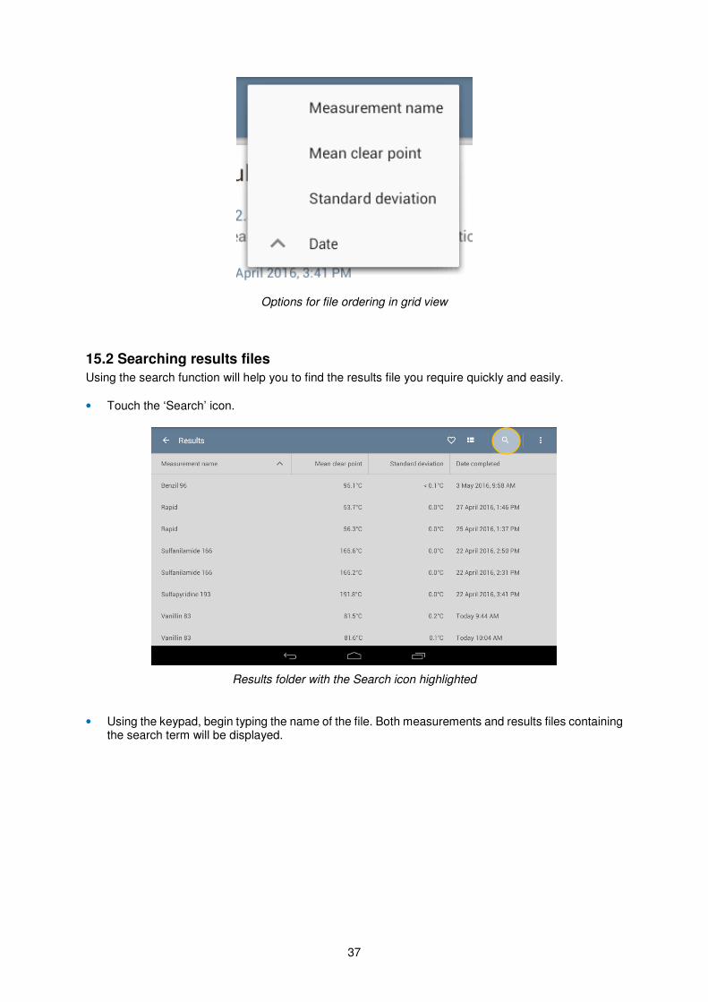
• Touch the ‘Sort’ icon to change the display order when in Grid view. You will have the option to order files by measurement name, mean clear point, standard deviation or date completed.
37
Options for file ordering in grid view
15.2 Searching results files
Using the search function will help you to find the results file you require quickly and easily.
• Touch the ‘Search’ icon.
Results folder with the Search icon highlighted
• Using the keypad, begin typing the name of the file. Both measurements and results files containing the search term will be displayed.
38
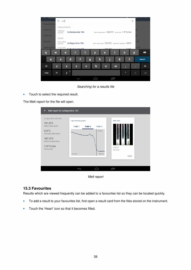
Searching for a results file
• Touch to select the required result. The Melt report for the file will open.
Melt report
15.3 Favourites
Results which are viewed frequently can be added to a favourites list so they can be located quickly.
• To add a result to your favourites list, first open a result card from the files stored on the instrument.
• Touch the ‘Heart’ icon so that it becomes filled.
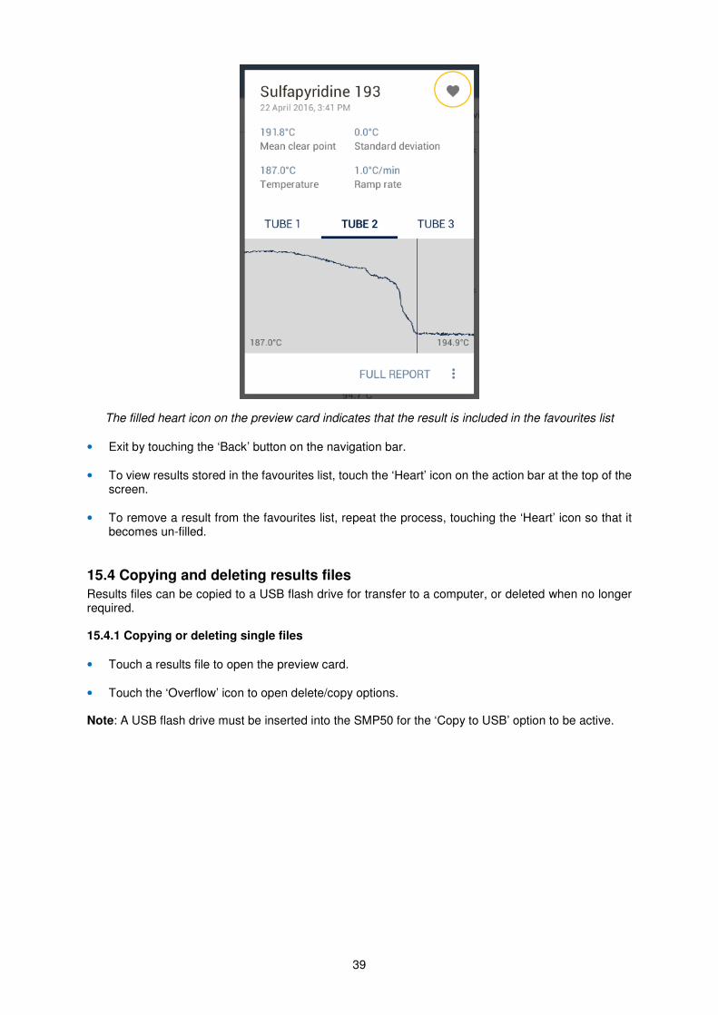
39
The filled heart icon on the preview card indicates that the result is included in the favourites list
• Exit by touching the ‘Back’ button on the navigation bar.
• To view results stored in the favourites list, touch the ‘Heart’ icon on the action bar at the top of the screen.
• To remove a result from the favourites list, repeat the process, touching the ‘Heart’ icon so that it becomes un-filled.
15.4 Copying and deleting results files
Results files can be copied to a USB flash drive for transfer to a computer, or deleted when no longer required. 15.4.1 Copying or deleting single files
• Touch a results file to open the preview card.
• Touch the ‘Overflow’ icon to open delete/copy options.
Note: A USB flash drive must be inserted into the SMP50 for the ‘Copy to USB’ option to be active.
40
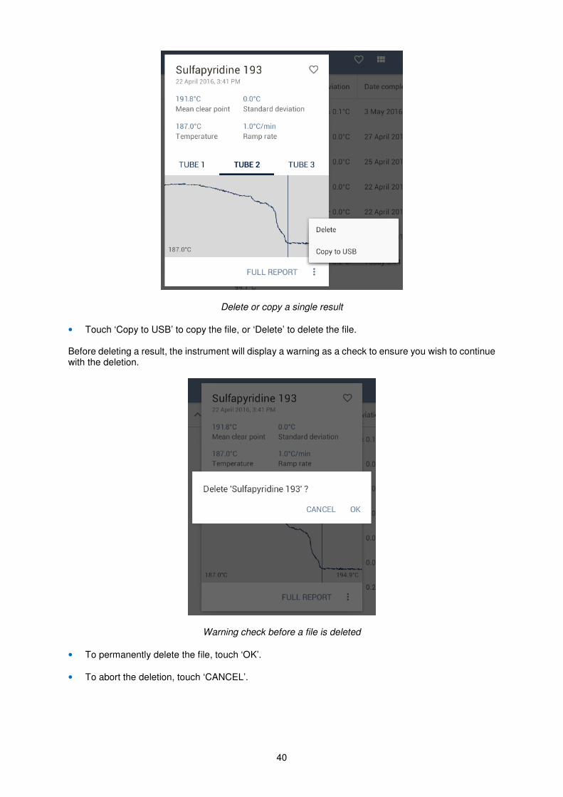
Delete or copy a single result
• Touch ‘Copy to USB’ to copy the file, or ‘Delete’ to delete the file. Before deleting a result, the instrument will display a warning as a check to ensure you wish to continue with the deletion.
Warning check before a file is deleted
• To permanently delete the file, touch ‘OK’.
• To abort the deletion, touch ‘CANCEL’.
41
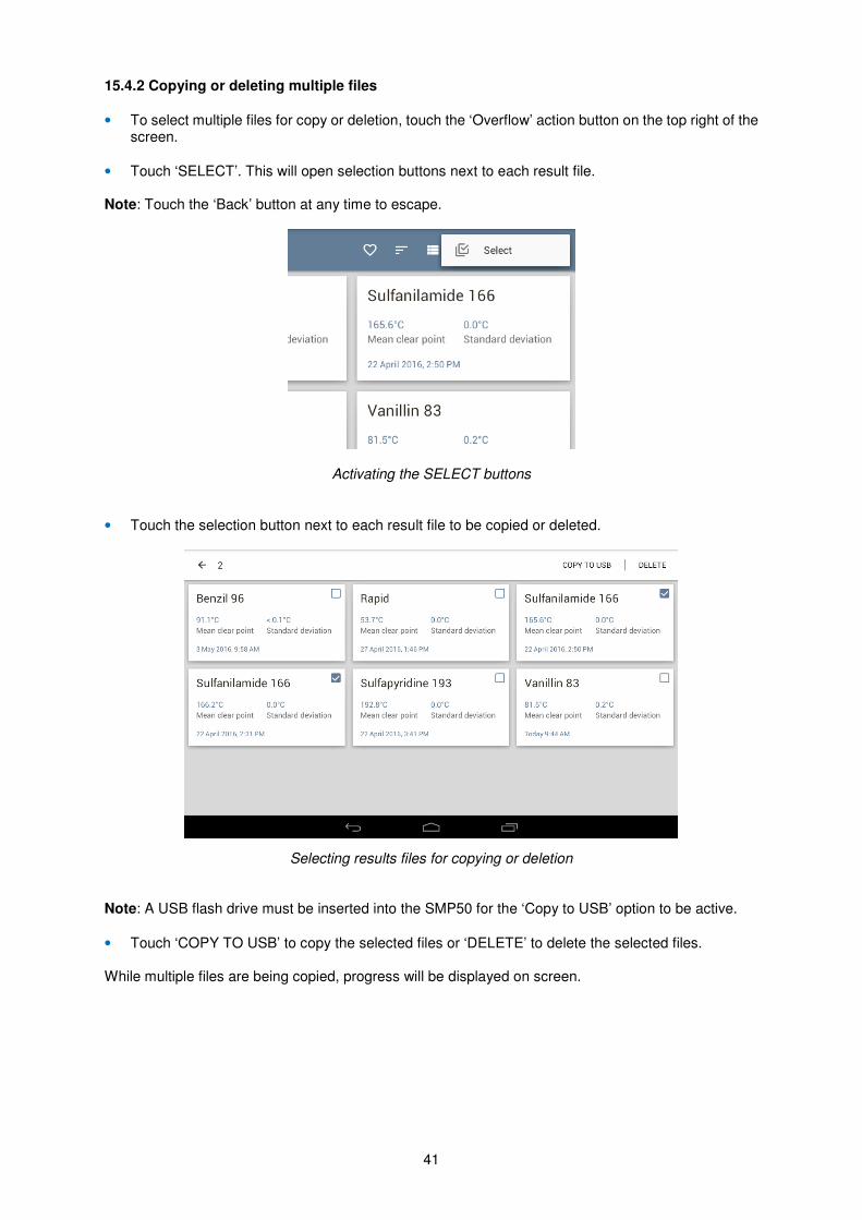
15.4.2 Copying or deleting multiple files
• To select multiple files for copy or deletion, touch the ‘Overflow’ action button on the top right of the screen.
• Touch ‘SELECT’. This will open selection buttons next to each result file. Note: Touch the ‘Back’ button at any time to escape.
Activating the SELECT buttons
• Touch the selection button next to each result file to be copied or deleted.
Selecting results files for copying or deletion Note: A USB flash drive must be inserted into the SMP50 for the ‘Copy to USB’ option to be active.
• Touch ‘COPY TO USB’ to copy the selected files or ‘DELETE’ to delete the selected files. While multiple files are being copied, progress will be displayed on screen.
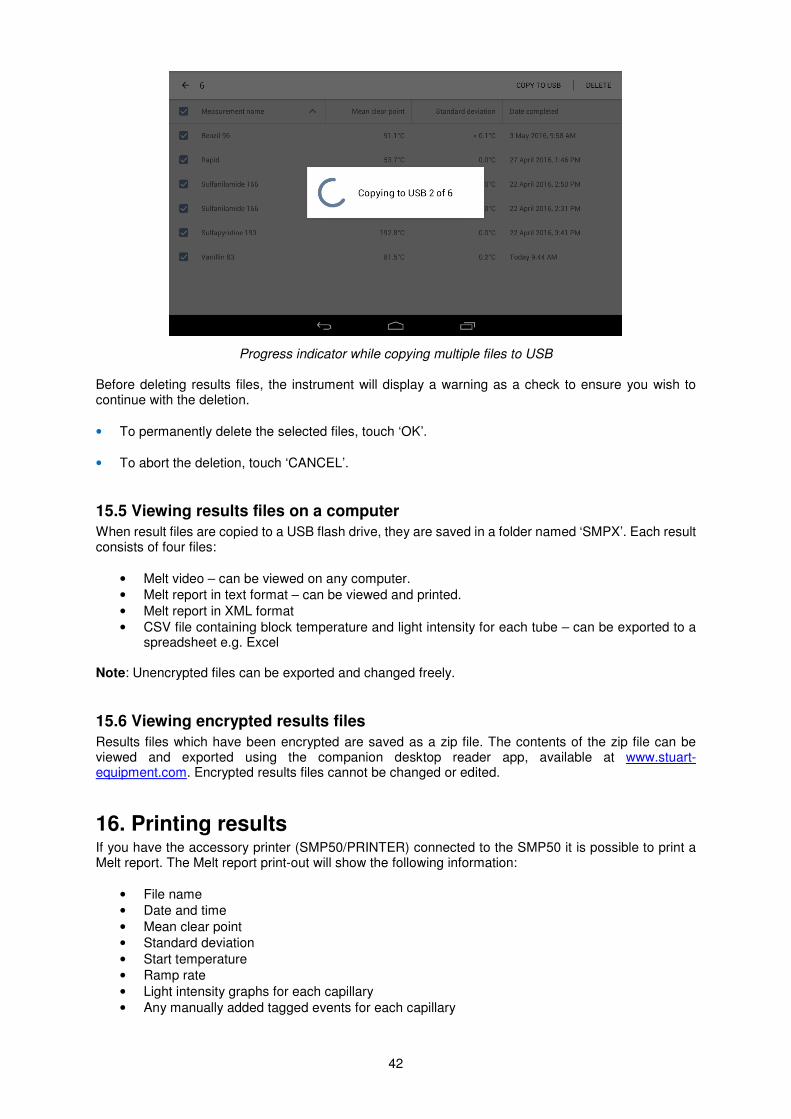
42
Progress indicator while copying multiple files to USB Before deleting results files, the instrument will display a warning as a check to ensure you wish to continue with the deletion.
• To permanently delete the selected files, touch ‘OK’.
• To abort the deletion, touch ‘CANCEL’.
15.5 Viewing results files on a computer
When result files are copied to a USB flash drive, they are saved in a folder named ‘SMPX’. Each result consists of four files:
• Melt video – can be viewed on any computer.
• Melt report in text format – can be viewed and printed.
• Melt report in XML format
• CSV file containing block temperature and light intensity for each tube – can be exported to a spreadsheet e.g. Excel
Note: Unencrypted files can be exported and changed freely.
15.6 Viewing encrypted results files
Results files which have been encrypted are saved as a zip file. The contents of the zip file can be viewed and exported using the companion desktop reader app, available at www.stuart-equipment.com. Encrypted results files cannot be changed or edited.
16. Printing results If you have the accessory printer (SMP50/PRINTER) connected to the SMP50 it is possible to print a Melt report. The Melt report print-out will show the following information:
• File name
• Date and time
• Mean clear point
• Standard deviation
• Start temperature
• Ramp rate
• Light intensity graphs for each capillary
• Any manually added tagged events for each capillary
43
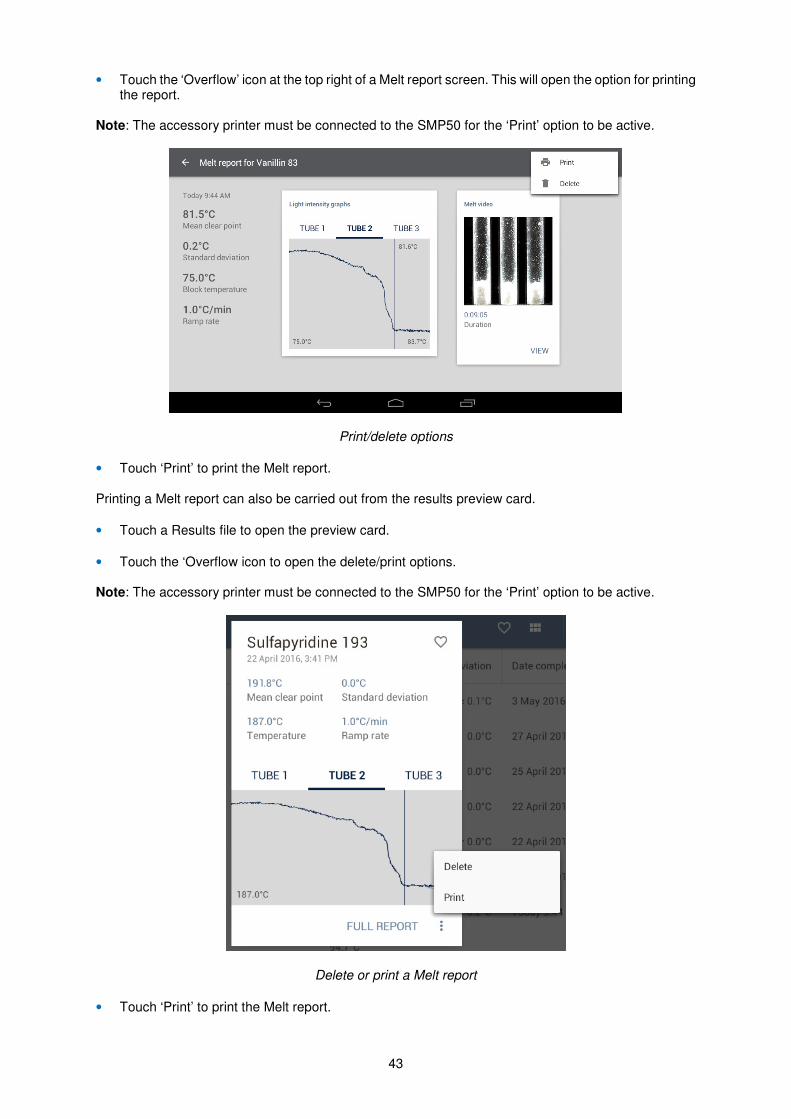
• Touch the ‘Overflow’ icon at the top right of a Melt report screen. This will open the option for printing the report.
Note: The accessory printer must be connected to the SMP50 for the ‘Print’ option to be active.
Print/delete options
• Touch ‘Print’ to print the Melt report. Printing a Melt report can also be carried out from the results preview card.
• Touch a Results file to open the preview card.
• Touch the ‘Overflow icon to open the delete/print options. Note: The accessory printer must be connected to the SMP50 for the ‘Print’ option to be active.
Delete or print a Melt report
• Touch ‘Print’ to print the Melt report.
44
17. Instrument Calibration The SMP50 is factory calibrated to the specifications shown on the certificate supplied with the instrument. To ensure that the instrument is continuing to operate within specification, periodic checks on the accuracy of the temperature readings are recommended. If the accuracy of the instrument is found to deviate from the specification or if it is a requirement of your local quality policy, the user calibration procedure can be used to recalibrate the displayed temperature on the instrument.
The main menu screen displays the date on which a previous user calibration was performed and the ‘Notifications’ menu in ‘Settings’ will enable an alert to be set up as a reminder for calibration and can be set to Never (default), Weekly, Monthly, Bi-annually or Annually. If no previous user calibration has been performed, the main screen will display ‘Factory calibration’.
It is recommended that the calibration procedure is performed using suitable certified melting point standards which bracket the expected range of your test samples. This will ensure the highest level of confidence is maintained in the results generated with the instrument. A list of commonly used melting point standards and nominal melting points is given below.
Name Nominal Melting point*
Azobenzene 69
Vanillin 83
Benzil 96
Acetanilide 116
Phenacetin 136
Benzanilide 165
Sulfanilamide 166
Sulfapyridine 193
Dicyanodiamide 210
Saccharin 230
Caffeine 237
Phenolphthalein 263
*Note: Confirm the certified melting point and melting point range with the certificate supplied with the standard.
17.1 Calibration procedure
Before the calibration is carried out it is necessary to perform melting point determinations with up to three certified melting point standards.
• Prepare the melting point standards following the guidelines given in section 11.1. For the most accurate results, prepare three capillaries for each standard.
• Create a new measurement for each standard and run a melting point determination. Save the results.
• From the main menu screen, touch the Calibration card to open the calibration summary screen.
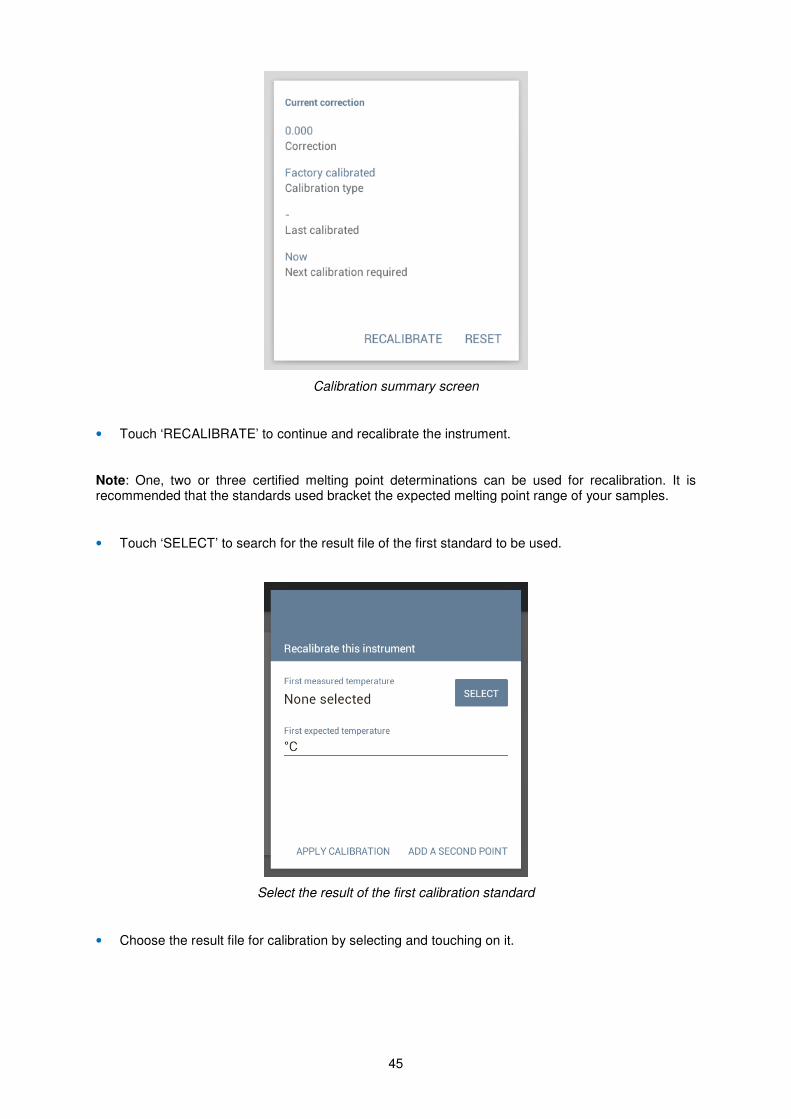
The calibration summary screen displays the following information:
Correction: Value of the current correction factor. This will be 0.000 for factory calibration and will be updated when a user calibration is performed.
Calibration type: Factory calibrated or user calibrated.
Last calibrated: Displays the date of the previous user calibration.
Next calibration required:
Displays the date when the next user calibration is due, depending on the frequency reminder in the Settings.
45
Calibration summary screen
• Touch ‘RECALIBRATE’ to continue and recalibrate the instrument.
Note: One, two or three certified melting point determinations can be used for recalibration. It is recommended that the standards used bracket the expected melting point range of your samples.
• Touch ‘SELECT’ to search for the result file of the first standard to be used.
Select the result of the first calibration standard
• Choose the result file for calibration by selecting and touching on it.
46
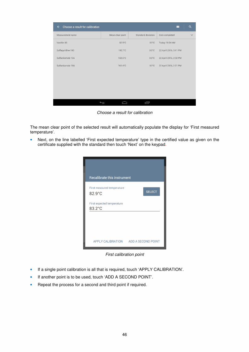
Choose a result for calibration
The mean clear point of the selected result will automatically populate the display for ‘First measured temperature’.
• Next, on the line labelled ‘First expected temperature’ type in the certified value as given on the certificate supplied with the standard then touch ‘Next’ on the keypad.
First calibration point
• If a single point calibration is all that is required, touch ‘APPLY CALIBRATION’.
• If another point is to be used, touch ‘ADD A SECOND POINT’.
• Repeat the process for a second and third point if required.
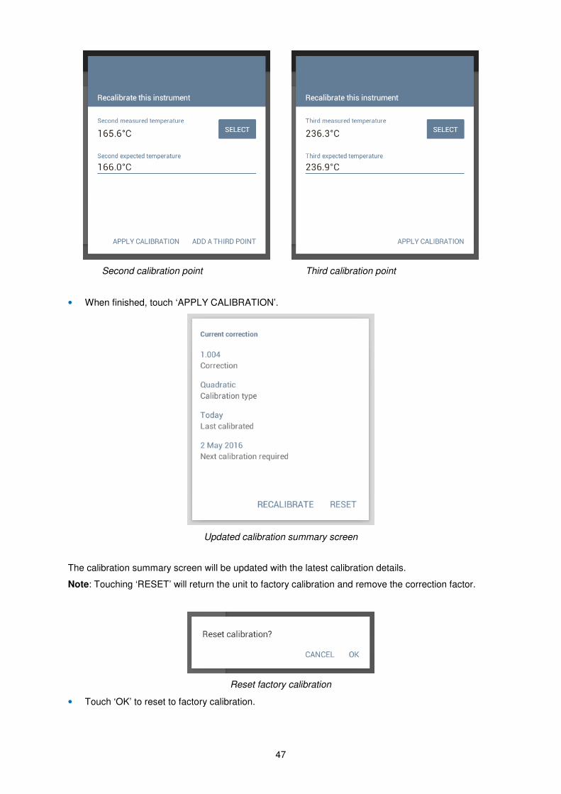
47
Second calibration point Third calibration point
• When finished, touch ‘APPLY CALIBRATION’.
Updated calibration summary screen
The calibration summary screen will be updated with the latest calibration details.
Note: Touching ‘RESET’ will return the unit to factory calibration and remove the correction factor.
Reset factory calibration
• Touch ‘OK’ to reset to factory calibration.
48
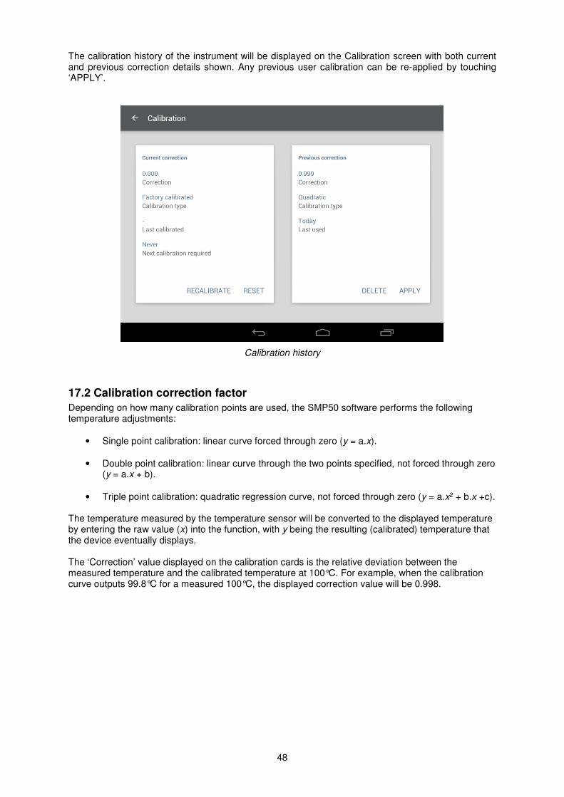
The calibration history of the instrument will be displayed on the Calibration screen with both current and previous correction details shown. Any previous user calibration can be re-applied by touching ‘APPLY’.
Calibration history
17.2 Calibration correction factor
Depending on how many calibration points are used, the SMP50 software performs the following temperature adjustments:
• Single point calibration: linear curve forced through zero (y = a.x).
• Double point calibration: linear curve through the two points specified, not forced through zero (y = a.x + b).
• Triple point calibration: quadratic regression curve, not forced through zero (y = a.x2 + b.x +c).
The temperature measured by the temperature sensor will be converted to the displayed temperature by entering the raw value (x) into the function, with y being the resulting (calibrated) temperature that the device eventually displays. The ‘Correction’ value displayed on the calibration cards is the relative deviation between the measured temperature and the calibrated temperature at 100°C. For example, when the calibration curve outputs 99.8°C for a measured 100°C, the displayed correction value will be 0.998.
49
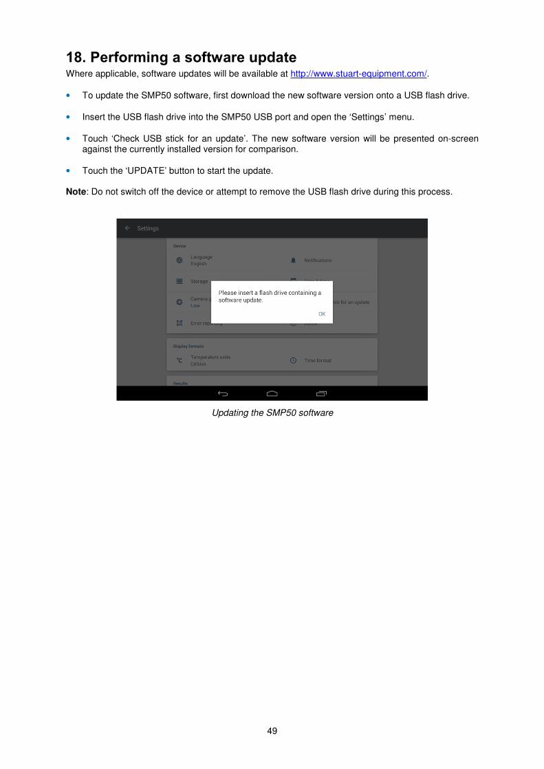
18. Performing a software update Where applicable, software updates will be available at http://www.stuart-equipment.com/.
• To update the SMP50 software, first download the new software version onto a USB flash drive.
• Insert the USB flash drive into the SMP50 USB port and open the ‘Settings’ menu.
• Touch ‘Check USB stick for an update’. The new software version will be presented on-screen against the currently installed version for comparison.
• Touch the ‘UPDATE’ button to start the update. Note: Do not switch off the device or attempt to remove the USB flash drive during this process.
Updating the SMP50 software
50
19. Maintenance and servicing WARNING: Ensure the unit is disconnected from the mains electricity supply before attempting maintenance or servicing.
This equipment does not require routine servicing and there are no serviceable parts within the equipment.
The only user maintenance required is to clean external surfaces using a damp cloth and mild detergent solution. Do not use harsh or abrasive cleaning agents.
Before cleaning the instrument:
• Switch off using the power switch and disconnect from the mains supply.
• Allow the instrument to cool for a period of at least 20 minutes.
• Do not allow liquids to ingress into the instrument case.
19.1 Fuse Replacement
If the display is not lit, one of the two fuses may have blown.
Please note that the replacement of fuses should only be carried out by a qualified electrician.
• Ensure the unit is disconnected from the mains supply before commencing the replacement as described below.
• Firstly, check there is no external cause such as a faulty or damaged plug or lead. If faulty leads are identified, replace them before attempting to replace any of the fuses.
• The fuse holders are built into the mains input socket. With the power cable removed, open the fuse drawer using a suitable tool, such as a small flat-bladed screwdriver. Remove each fuse in turn and inspect to determine which has blown.
• Replace all blown fuses with a fuse of the following specification:
• F3.15A L 250v, 5x20mm glass bodied.
• Finally replace the fuse drawer, ensuring it is fully closed.
Please note that fuses which repeatedly blow indicate a serious fault and the unit should be returned to your supplier for repair.
19.2 Repairs and Support
Any repairs or replacement of parts MUST be undertaken by suitably qualified personnel. Only spare parts supplied or specified by Bibby Scientific or its agents should be used. Fitting of non-approved parts may affect the performance and safety features designed into the instrument. For a comprehensive list of parts required by service engineers conducting internal repairs please contact the service department quoting the model and serial number:
Email: [email protected]
Tel. +44 (0)1785 810475
Fax: +44 (0)1785 810471
For any other technical enquiries please contact the Technical Support Department at;
Email: [email protected]
Tel: +44 (0)1785 810433
51
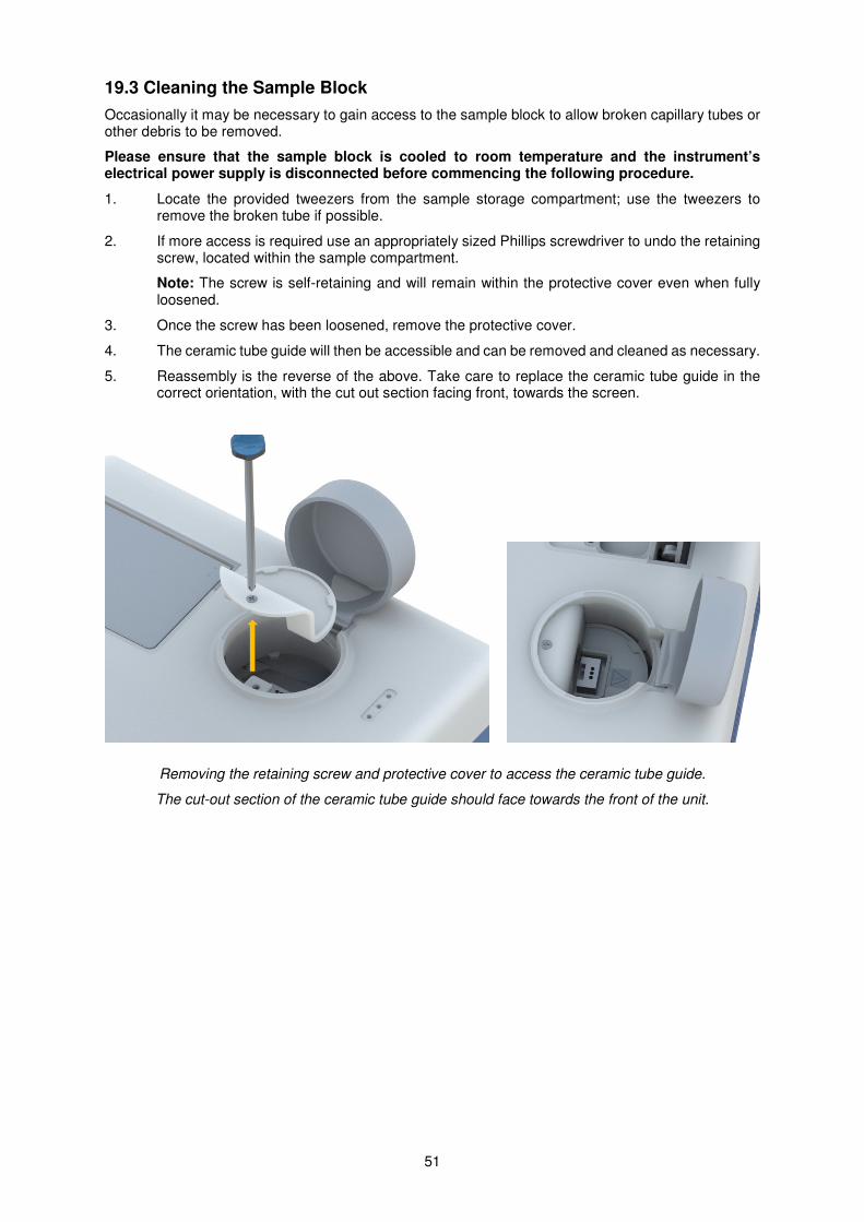
19.3 Cleaning the Sample Block
Occasionally it may be necessary to gain access to the sample block to allow broken capillary tubes or other debris to be removed.
Please ensure that the sample block is cooled to room temperature and the instrument’s electrical power supply is disconnected before commencing the following procedure.
1. Locate the provided tweezers from the sample storage compartment; use the tweezers to remove the broken tube if possible.
2. If more access is required use an appropriately sized Phillips screwdriver to undo the retaining screw, located within the sample compartment.
Note: The screw is self-retaining and will remain within the protective cover even when fully loosened.
3. Once the screw has been loosened, remove the protective cover.
4. The ceramic tube guide will then be accessible and can be removed and cleaned as necessary.
5. Reassembly is the reverse of the above. Take care to replace the ceramic tube guide in the correct orientation, with the cut out section facing front, towards the screen.
Removing the retaining screw and protective cover to access the ceramic tube guide.
The cut-out section of the ceramic tube guide should face towards the front of the unit.
52
20. Warranty Stuart warrants this instrument to be free from defects in material and workmanship, when used under normal laboratory conditions, for a period of 3 years. In the event of a justified claim Bibby Scientific Ltd will replace any defective component or replace the unit free of charge. This warranty does NOT apply if damage is caused by fire, accident, misuse, neglect, incorrect adjustment or repair, damage caused by incorrect installation, adaptation, modification, fitting of non-approved parts or repair by unauthorised personnel.
Bibby Scientific Ltd.
Stone
Staffordshire, ST15 0SA
United Kingdom
Tel: +44 (0) 1785 812121
Fax: +44 (0) 1785 813748
E-mail: [email protected]
Website: www.bibby-scientific.com
21. Specification Overall Dimensions:
Height: 164mm
Depth: 360mm
Width: 300mm
Weight: 4.6kg
Technical Specifications:
Temperature range Ambient to 400°C
Temperature resolution 0.1°C
Ramp rate 0.1°C to 20.0°C/minute
Cooling down time 350°C to 50°C ~ 12 minutes
Heating up time 50°C to 350°C ~ 6 minutes
Number of samples Up to three simultaneously
Display 7” HD Colour touch screen
Sensor PT1000 Platinum resistance
Memory storage 8GB (approximately 300 results with video)
Electrical supply 120V / 230V, 50-60Hz
Power 150W

53
22. Accessories The following accessories are available from your local distributor.
Description Catalogue Number
Capillaries, open at one end (pack of 100) SMP10/1
Capillaries, closed at both ends (pack of 100) SMP2/1
Printer SMP50/PRINTER
54
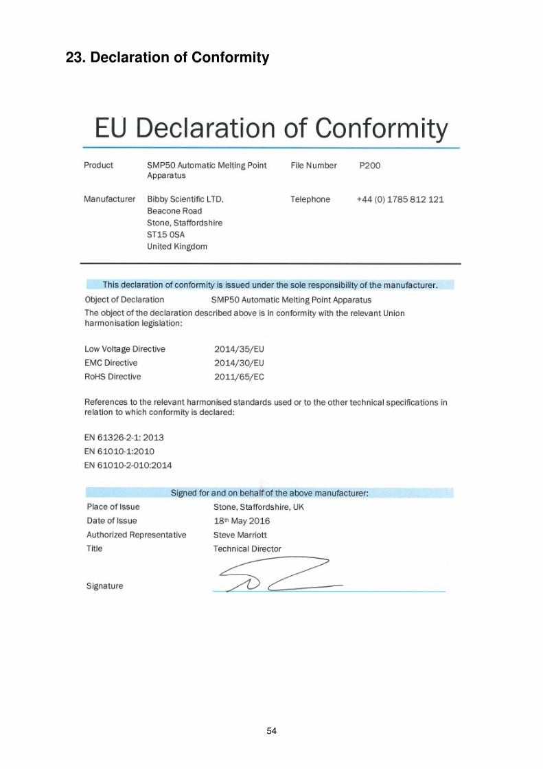
23. Declaration of Conformity

55
56
Bibby Scientific UK (Group HQ)
Beacon Road,
Stone,
Staffordshire
United Kingdom ST15 0SA
Tel: +44 (0) 1785 812121
Fax: +44 (0) 1785 810405
Email: [email protected]
Web: www.bibby-scientific.com
Bibby Scientific - France
Bâtiment le Deltaparc Silic pars Nord 2,
7 rue du Canal,
BP 55437 Villepinte,
95944 ROISSY Charles de Gaulle,
France
Tel: +33 (0) 1 48 63 78 00
Fax: +33 (0) 1 48 63 78 01
Email: [email protected]
Web: www.bibby-scientific.fr
Bibby Scientific - Middle East
PO Box 27842
Engomi 2433,
Nicosia, Cyprus
Tel: +357 22 660 423
Fax: +357 22 660 424
Email: [email protected]
Web: www.bibby-scientific.com